WO2009131082A1 - インデックステーブル - Google Patents
インデックステーブル Download PDFInfo
- Publication number
- WO2009131082A1 WO2009131082A1 PCT/JP2009/057823 JP2009057823W WO2009131082A1 WO 2009131082 A1 WO2009131082 A1 WO 2009131082A1 JP 2009057823 W JP2009057823 W JP 2009057823W WO 2009131082 A1 WO2009131082 A1 WO 2009131082A1
- Authority
- WO
- WIPO (PCT)
- Prior art keywords
- shaft
- rotation
- rotating
- rotating shaft
- axis
- Prior art date
- Legal status (The legal status is an assumption and is not a legal conclusion. Google has not performed a legal analysis and makes no representation as to the accuracy of the status listed.)
- Ceased
Links
Images



Classifications
-
- B—PERFORMING OPERATIONS; TRANSPORTING
- B23—MACHINE TOOLS; METAL-WORKING NOT OTHERWISE PROVIDED FOR
- B23Q—DETAILS, COMPONENTS, OR ACCESSORIES FOR MACHINE TOOLS, e.g. ARRANGEMENTS FOR COPYING OR CONTROLLING; MACHINE TOOLS IN GENERAL CHARACTERISED BY THE CONSTRUCTION OF PARTICULAR DETAILS OR COMPONENTS; COMBINATIONS OR ASSOCIATIONS OF METAL-WORKING MACHINES, NOT DIRECTED TO A PARTICULAR RESULT
- B23Q1/00—Members which are comprised in the general build-up of a form of machine, particularly relatively large fixed members
- B23Q1/25—Movable or adjustable work or tool supports
- B23Q1/44—Movable or adjustable work or tool supports using particular mechanisms
- B23Q1/50—Movable or adjustable work or tool supports using particular mechanisms with rotating pairs only, the rotating pairs being the first two elements of the mechanism
- B23Q1/52—Movable or adjustable work or tool supports using particular mechanisms with rotating pairs only, the rotating pairs being the first two elements of the mechanism a single rotating pair
-
- B—PERFORMING OPERATIONS; TRANSPORTING
- B23—MACHINE TOOLS; METAL-WORKING NOT OTHERWISE PROVIDED FOR
- B23Q—DETAILS, COMPONENTS, OR ACCESSORIES FOR MACHINE TOOLS, e.g. ARRANGEMENTS FOR COPYING OR CONTROLLING; MACHINE TOOLS IN GENERAL CHARACTERISED BY THE CONSTRUCTION OF PARTICULAR DETAILS OR COMPONENTS; COMBINATIONS OR ASSOCIATIONS OF METAL-WORKING MACHINES, NOT DIRECTED TO A PARTICULAR RESULT
- B23Q11/00—Accessories fitted to machine tools for keeping tools or parts of the machine in good working condition or for cooling work; Safety devices specially combined with or arranged in, or specially adapted for use in connection with, machine tools
- B23Q11/001—Arrangements compensating weight or flexion on parts of the machine
- B23Q11/0017—Arrangements compensating weight or flexion on parts of the machine compensating the weight of vertically moving elements, e.g. by balancing liftable machine parts
- B23Q11/0021—Arrangements compensating weight or flexion on parts of the machine compensating the weight of vertically moving elements, e.g. by balancing liftable machine parts the elements being rotating or pivoting
-
- B—PERFORMING OPERATIONS; TRANSPORTING
- B23—MACHINE TOOLS; METAL-WORKING NOT OTHERWISE PROVIDED FOR
- B23Q—DETAILS, COMPONENTS, OR ACCESSORIES FOR MACHINE TOOLS, e.g. ARRANGEMENTS FOR COPYING OR CONTROLLING; MACHINE TOOLS IN GENERAL CHARACTERISED BY THE CONSTRUCTION OF PARTICULAR DETAILS OR COMPONENTS; COMBINATIONS OR ASSOCIATIONS OF METAL-WORKING MACHINES, NOT DIRECTED TO A PARTICULAR RESULT
- B23Q11/00—Accessories fitted to machine tools for keeping tools or parts of the machine in good working condition or for cooling work; Safety devices specially combined with or arranged in, or specially adapted for use in connection with, machine tools
- B23Q11/001—Arrangements compensating weight or flexion on parts of the machine
- B23Q11/0028—Arrangements compensating weight or flexion on parts of the machine by actively reacting to a change of the configuration of the machine
-
- Y—GENERAL TAGGING OF NEW TECHNOLOGICAL DEVELOPMENTS; GENERAL TAGGING OF CROSS-SECTIONAL TECHNOLOGIES SPANNING OVER SEVERAL SECTIONS OF THE IPC; TECHNICAL SUBJECTS COVERED BY FORMER USPC CROSS-REFERENCE ART COLLECTIONS [XRACs] AND DIGESTS
- Y10—TECHNICAL SUBJECTS COVERED BY FORMER USPC
- Y10T—TECHNICAL SUBJECTS COVERED BY FORMER US CLASSIFICATION
- Y10T409/00—Gear cutting, milling, or planing
- Y10T409/30—Milling
- Y10T409/304536—Milling including means to infeed work to cutter
- Y10T409/305544—Milling including means to infeed work to cutter with work holder
- Y10T409/305656—Milling including means to infeed work to cutter with work holder including means to support work for rotation during operation
- Y10T409/305824—Milling including means to infeed work to cutter with work holder including means to support work for rotation during operation with angular movement of work
-
- Y—GENERAL TAGGING OF NEW TECHNOLOGICAL DEVELOPMENTS; GENERAL TAGGING OF CROSS-SECTIONAL TECHNOLOGIES SPANNING OVER SEVERAL SECTIONS OF THE IPC; TECHNICAL SUBJECTS COVERED BY FORMER USPC CROSS-REFERENCE ART COLLECTIONS [XRACs] AND DIGESTS
- Y10—TECHNICAL SUBJECTS COVERED BY FORMER USPC
- Y10T—TECHNICAL SUBJECTS COVERED BY FORMER US CLASSIFICATION
- Y10T74/00—Machine element or mechanism
- Y10T74/14—Rotary member or shaft indexing, e.g., tool or work turret
-
- Y—GENERAL TAGGING OF NEW TECHNOLOGICAL DEVELOPMENTS; GENERAL TAGGING OF CROSS-SECTIONAL TECHNOLOGIES SPANNING OVER SEVERAL SECTIONS OF THE IPC; TECHNICAL SUBJECTS COVERED BY FORMER USPC CROSS-REFERENCE ART COLLECTIONS [XRACs] AND DIGESTS
- Y10—TECHNICAL SUBJECTS COVERED BY FORMER USPC
- Y10T—TECHNICAL SUBJECTS COVERED BY FORMER US CLASSIFICATION
- Y10T83/00—Cutting
- Y10T83/869—Means to drive or to guide tool
- Y10T83/8821—With simple rectilinear reciprocating motion only
- Y10T83/8824—With provision for dynamic balance
Definitions
- the present invention relates to an index table in which a rotating shaft that supports a table to which a workpiece is fixed extends in a direction intersecting the vertical direction, for example, an inclined circular table or the like.
- the center of gravity of the driven body consisting of a member or object supported by the rotation axis, that is, a table to which the workpiece is fixed, a workpiece mounting jig, a workpiece, etc.
- the position may be greatly deviated from the axis of the rotating shaft.
- the tilt index table has a rotating shaft extending in the horizontal direction, and the table on which the workpiece is fixed has a position of the center of gravity greatly deviated from the axis of the rotating shaft.
- the center of gravity position of the driven body moves to the rotating shaft side by mounting the workpiece and workpiece mounting jig, and the deviation from the shaft center is somewhat eliminated, but the rotational torque applied to the rotating shaft due to the heavy weight of the driven body That is, the unbalance torque due to the deviation of the position of the center of gravity increases. Since the unbalance torque varies depending on the index angle, the unbalance torque greatly varies with the rotation index. For this reason, the drive motor for the rotating shaft requires a large capacity commensurate with load fluctuations. In addition, the drive transmission member such as the coupling and shaft, and the rotating shaft must be sufficiently rigid to meet the load fluctuations in order to avoid losing the indexing accuracy due to twisting, especially the degree of twisting that differs for each indexing angle. And
- an unbalance torque compensator shown in FIG. 6 is known and applied to a tilt index table.
- the rotating shaft 91 of the table 2 to which the workpiece is fixed, the first gear 93 fixed to the rotating shaft 91, and the second gear having the same number of teeth are engaged with the first gear 93.
- a hydraulic cylinder device having a piston 98 connected to the other end of the crank arm 95.
- the direction of the urging force F of the fluid pressure cylinder device is orthogonal to the axis of the second shaft 92 (Patent Document 1).
- the first rotational torque T1 in the clockwise direction is applied to the rotation shaft 91 as an unbalance torque, and the first rotation torque T1 is applied from the axis of the rotation shaft 91 to the center of gravity G of the driven body.
- T1 Wg ⁇ R1 ⁇ sin ⁇ .
- the force that the urging force F acts on the crankpin 97 via the pin 96 and the crank arm 95 is F ⁇ cos ⁇ , and the tangent line of the crankpin 97, that is, the crankpin 97 and the second shaft 92. It intersects at 90 ° - ⁇ - ⁇ with the orthogonal line connecting the axes.
- the second hydraulic torque T2 is applied to the second gear 94 by the fluid pressure cylinder device, and the second rotational torque T2 is applied from the axis of the second shaft 92 to the crankpin 97.
- R2 is R2
- T2 R2 ⁇ F ⁇ cos ⁇ ⁇ sin ( ⁇ + ⁇ ).
- the second clockwise torque T2 of the second gear 94 is transmitted to the rotary shaft 91 via the meshing first gear 93, and acts as a counterclockwise rotary torque on the rotary shaft 91. Acts as compensation torque in the opposite direction to the unbalance torque. Accordingly, the rotation shaft 91 has the following rotation obtained by subtracting the second rotation torque T2 due to the hydraulic cylinder device, that is, the compensation torque, from the first rotation torque T1 in the clockwise direction due to the gravity Wg, ie, the unbalance torque. The absolute value of the torque is added as a correction torque in the clockwise direction or the counterclockwise direction, and the load on the drive motor and the like of the rotating shaft 91 is reduced.
- T1-T2 Wg ⁇ R1 ⁇ sin ⁇ R2 ⁇ F ⁇ cos ⁇ ⁇ sin ( ⁇ + ⁇ )
- ⁇ is a function of ⁇
- the correction torque T1-T2 is a function of ⁇ , and therefore changes with the rotation angle ⁇ of the table 2. Therefore, in order to keep the correction torque T1-T2 as small as possible and keep it constant, it is necessary to change the urging force F of the fluid pressure cylinder device as the table 2 rotates. Control of the urging force F is required.
- an unbalance torque compensation device different from the above-described device is known, and instead of connecting the fluid pressure cylinder device to the second gear and applying a biasing force, a balance weight is applied to the second gear.
- the unbalance torque is compensated by attaching
- the balance weight is attached to the second gear at a position deviated from the axis, and a swirl space is provided in order to avoid interference with other devices and injury to the operator (Patent Document 2). ).
- the present invention is premised on an index table that supports a table on which a workpiece is fixed and is indexed and driven by a rotating shaft extending in a direction intersecting the vertical direction.
- the present invention is fixed to the rotating shaft or supported by a second shaft different from the rotating shaft, and the rotation of the rotating shaft is transmitted through the rotation transmitting mechanism to rotate by the same amount as the rotating shaft.
- a rotating member a support member provided so as to be able to reciprocate in a direction intersecting the axis of the rotating member, and a biasing member of the support member, and the rotating member is engaged with the support member at a biased position separated from the shaft center.
- the supporting member has an engaging surface that receives the first rotational torque applied to the rotating shaft by the weight supported by the rotating shaft through the engaging portion, and the biasing member is The second rotation torque in a direction opposite to the first rotation torque is generated on the rotation shaft via the engagement portion.
- the rotating body is supported by the second shaft, and the rotation transmission mechanism is supported by the first circular member fixed to the rotating shaft and the second shaft. 1 and a second circular member having the same diameter, and the first and second circular members transmit rotation to each other directly or via an intermediate member, whereby the rotating body rotates by the same amount as the rotation shaft. You may make it do.
- the engagement portion with respect to the rotating body is arranged so that the second rotational torque is maximized or substantially maximized when the first rotational torque is maximum in the rotation range of the rotation shaft.
- the phase may be set.
- a displacement regulating device for the support member is provided.
- the displacement restricting device is provided with two restricting members disposed on one side and the other side of the axis of the rotating shaft to which the rotating body is fixed or the axis of the second shaft on which the rotating body is supported.
- two moving members that are provided on the support member and respectively come into contact with the regulating member, and one of the regulating member and the moving member arranged on the one side is parallel to the reciprocating direction of the supporting member.
- the other has a sliding contact surface in sliding contact with the guide surface, or a plurality of rolling elements in contact with the guide surface, and a regulating member and a moving member disposed on the other side
- One has a guide surface formed in parallel with the reciprocating direction of the support member, and the other has a sliding contact surface that is in sliding contact with the guide surface, or a plurality of rolling elements that are in contact with the guide surface.
- the rotating body is fixed to the rotating shaft, or is supported by the second shaft different from the rotating shaft and rotates by the same amount as the rotating shaft via the rotation transmission mechanism.
- the engaging portion of the rotating body rotates by the same amount as the rotating shaft.
- the support member is provided so as to be able to reciprocate in the direction intersecting the axis of the rotating body, the biasing force of the biasing member is parallel to the direction intersecting the axis of the rotating body via the support member. Acts on the engaging portion. Therefore, the second rotational torque applied to the rotating body changes more accurately in response to the change of the first rotational torque applied to the rotating shaft with the rotation of the rotating shaft due to the weight supported by the rotating shaft. For this reason, the rotational torque applied to the rotating body is reduced, and the load of the driving source for indexing and driving the rotating shaft is reduced.
- the rotating body is not fixed to the rotating shaft but is supported by a second shaft different from the rotating shaft, and is supported by the second shaft and the first circular member fixed to the rotating shaft.
- the first circular member and the second circular member having the same diameter are rotated via a rotation transmission mechanism, so that the phase relationship between the first circular member and the second circular member is adjusted. Since the work can be performed while avoiding the interference of the biasing member, the phase relationship between the rotating shaft and the rotating body can be easily adjusted.
- the phase of the center of gravity position with respect to the rotating shaft changes as the workpiece and the workpiece mounting jig change.
- the phase of the engaging portion with respect to the rotating body is set so that the second rotational torque is maximized or substantially maximized when the first rotational torque is maximum.
- the first rotational torque can be efficiently compensated and reduced by the second rotational torque.
- FIG. 2 is a left side view of FIG. 1 showing an embodiment of the index table of the present invention.
- the modification of embodiment of the index table of this invention is shown.
- the another modification of embodiment of the index table of this invention is shown.
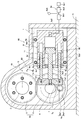
- FIG. 1 is a front view showing the overall structure of one embodiment of an index table
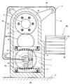
- FIG. 2 is a left side view of FIG.
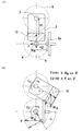
- FIG. 5 is a schematic diagram showing the positional relationship between the center of gravity G of the driven body supported by the rotating shaft 3 and the engaging portion 6a, and the relationship between the unbalance torque and the compensation torque.
- the rotary shaft 3 that supports the table 2 on which the workpiece 31 is placed, which is applied to a so-called tilted index table that is processed by tilting the workpiece 31 supported at a predetermined angle, It extends in the horizontal direction and is orthogonal to the vertical direction.
- the tilt index table has, as its basic configuration, a frame 1 installed on a horizontal or tilted surface of a machine tool bed 71 and the like, and a table 2 that is rotatably supported with respect to the frame 1 and on which a work 31 is placed. And a rotating shaft 3 that is supported by the frame 1 and fixed to the table 2 and rotatably supports the table 2 with respect to the frame 1.
- the frame 1 is installed on a horizontal plane.
- the frame 1 has a U-shape with an opening on the rotating shaft side, and has a pair of support frames 1a that are erected apart from the left and right sides of the table 2, and a lower end portion of the pair of support frames 1a that extends to the left and right.
- the base frame 1b is connected to the bed 71 with bolts or the like.
- the table 2 is disposed inside the frame 1. Like the frame 1, the table 2 is formed in a U shape with an opening on the rotating shaft side, and a pair of arms 2 a erected apart from the left and right sides, and a pair of arms It is comprised from the base 2b which connects the one end part of the arm 2a.
- the rotating shaft 3 is formed separately by a driving-side rotating shaft 3a (right side in FIG. 1) and a driven-side rotating shaft 3b and protrudes inward in the axial direction, and penetrates the pair of arms 2a of the table 2 respectively. Then, they are respectively fitted into a pair of fitting holes 2a1 that are coaxial with each other, are rendered immovable relative to each other via the key K and a push screw (not shown), and are integrated with the table 2.
- the driving side rotating shaft 3 a and the driven side rotating shaft 3 b are coaxially connected to each other via the table 2 to form one rotating shaft 3.
- a pair of bearings 21 are fitted coaxially to the pair of support frames 1a.
- a drive-side rotary shaft 3a and a driven-side rotary shaft 3b are inserted into the inner ring of each bearing 21, and the table 2 is rotatably supported by the frame 1 in a state where both ends are supported.
- the drive-side rotary shaft 3a is connected to a drive motor via a rotation transmission device such as a worm reduction device and a coupling (not shown).
- the drive side rotating shaft 3a may constitute a rotor shaft of a driving motor and may be directly driven without using a rotation transmission device.
- the base 2b of the table 2 has a workpiece placement surface parallel to the rotation shaft 3, and the workpiece placement surface is provided as a fixed surface integrally with the main body portion of the base 2b.
- the main body portion is rotatably supported and is provided so as to be able to rotate and index about an axis orthogonal to the rotation shaft 3.
- the workpiece placement surface is fixed by bolts, a metallurgy, or the like with the workpiece 31 directly or via the attachment workpiece attachment jig 23 as shown in FIG.
- the index table of the present invention includes a rotating body provided on a second shaft 4 different from the rotating shaft 3, a rotation transmission mechanism 50 that rotates the rotating body by the same amount as the rotating shaft 3, and rotation.
- the engaging portion 6a provided on the body, the support member 7 receiving the first rotational torque T1 generated in the rotating shaft 3 from the rotating body via the engaging portion 6a, and the rotating body counters the first rotating torque T1.
- it includes a biasing member 80 that biases the support member 7, a displacement regulating device 60 for the support member 7, and a case 10 that houses these members and the device.
- the support frame 1 a that supports the driven side rotation shaft 3 b has a second shaft 4, which is different from the rotation shaft 3, in parallel with the rotation shaft 3 via a bearing 22.
- the second shaft 4 and the driven side rotation shaft 3b are supported and protrude outside the support frame 1a.
- a first gear 5 and a second gear 6 having the same number of teeth are fixed to the flange 3b1 of the driven side rotating shaft 3b and the flange 4a of the second shaft 4 detachably through bolts, respectively.
- the first gear 5 and the second gear 6 are meshed with each other, and become a first circular member fixed to the rotary shaft 3 and a second circular member supported by the second shaft 4.
- a rotation transmission mechanism 50 is configured.
- the second gear 6 constitutes a second circular member and a rotating body by being provided with an engaging portion 6a. That is, the pin 6a1 is erected by screwing on the side surface of the second gear 6 opposite to the table 2 at a position deviated from the axis of the second shaft 4, and the roller 6a2 is rotatably supported.
- the pin 6a1 and the roller 6a2 constitute an engaging portion 6a that comes into contact with an engaging surface 7a of the supporting member 7 described later and engages with the supporting member 7. Therefore, the second gear 6 has a radially outer portion that constitutes the second circular member and meshes with the first gear 5 that constitutes the first circular member, and the radially inner portion has the engaging portion 6a.
- the rotating body is configured.
- the case 10 is fixed to the outside of the support frame 1a that supports the driven side rotation shaft 3b, and the case 10 is provided with a fluid pressure cylinder device 8 as an urging member 80.
- the fluid pressure cylinder device 8 is connected to a cylinder block 8a fixed to the support frame 1a with a bolt, a piston 8b that reciprocates within the cylinder block 8a, a cylinder head 8c that closes an open end of the cylinder block 8a, and a piston 8b.
- a fluid supply circuit 8e that includes a piston rod 8d that protrudes outward from the cylinder head 8c and that supplies high-pressure fluid into the cylinder block 8a.
- the cylinder block 8 a is formed in a bottomed cylindrical shape, and the extending direction of the axis, that is, the reciprocating direction of the piston 8 b passes through the axis of the second shaft 4 and intersects the axis of the second shaft 4.
- Direction in the present embodiment, the direction orthogonal.
- the cylinder head 8c has an air vent hole 8c1 that communicates the internal space of the cylinder block 8a with the outside, an insertion hole 8c2 through which the piston rod 8d is inserted, and a guide bush 8c3 provided in the insertion hole 8c2.
- a rectangular parallelepiped support member 7 is fixed to the tip of the piston rod 8d.
- the fluid supply circuit 8e switches between supply and stop of fluid supply to a high-pressure fluid supply source 8e1 composed of a compressor or a hydraulic pump, a regulator 8e2 that adjusts the pressure of the fluid from the high-pressure fluid supply source 8e1, and a pressure gauge 8e4.
- the on-off valve 8e3 and a flow path 8e5 that connects the on-off valve 8e3 and a pressure chamber formed in the cylinder block 8a.
- the urging force of the fluid pressure cylinder device 8 is set by adjusting the pressure of the fluid from the high pressure fluid supply source 8e1 by manual operation of the regulator 8e2.
- the driven body composed of the work 31, the work attachment jig 23, and the table 2 is located at a position deviated from the axis of the rotary shaft 3.
- a center of gravity G is arranged. Except when the center of gravity G is located on a vertical line passing through the axis of the rotating shaft 3 (directly above or below the axis), a rotational torque is generated on the rotating shaft 3 by the weight of the driven body, that is, gravity.
- the position where the center of gravity G is on the vertical line passing through the axis of the rotary shaft 3 (directly below the axis in FIG.
- the engaging portion 6a rotates about the axis of the second shaft 4 by ⁇ in the clockwise direction.
- a predetermined force that is, a predetermined urging force from the fluid pressure cylinder device 8 is applied to the engaging portion 6 a through the engaging surface 7 a of the support member 7 in parallel with the direction intersecting the axis of the second shaft 4.
- the urging force of the fluid pressure cylinder device 8 is F
- the distance between the engaging portion 6a and the axis of the second gear 6 is R2
- the rotational torque T2 is expressed by the following equation as a clockwise rotational torque.
- T2 R2 ⁇ F ⁇ sin ⁇
- T1-T2 (R1 ⁇ Wg ⁇ R2 ⁇ F) ⁇ sin ⁇
- the work 31 attached to the work placement surface of the table 2 and the work attachment treatment so that R1 ⁇ Wg ⁇ R2 ⁇ F ⁇ 0, that is, F ⁇ R1 ⁇ Wg / R2.
- the table 23 is rotated from the reference position by adjusting the biasing force F of the fluid pressure cylinder device 8 in accordance with the change of the weight 23 of the driven body and the deviation amount R1 of the center of gravity G when the tool 23 is changed. It is shown that the correction torque is reduced regardless of the angle ⁇ .
- the setting of the urging force F of the fluid pressure cylinder device 8 and the setting of the phase between the second gear 6 as the rotating body and the rotating shaft 3 are performed as follows as an example.
- the work 31 and the work attachment jig 23 are attached to the table 2.
- the first gear 5 is removed from the rotating shaft 3.
- the drive motor is rotated at a low speed, determined based on the current value and the like, and stopped at the rotation angle with the largest load.
- the center of gravity G of the driven body is located on a horizontal line passing through the rotation shaft 3.
- the second gear 6 is rotated so that the engaging portion 6 a is positioned on a vertical line passing through the axis of the second shaft 4.
- the first gear 5 is attached to the rotary shaft 3 in a state in which the first gear 5 is engaged with the second gear 6.
- the flange 3b1 of the rotary shaft 3 is provided with female threads corresponding to the bolt holes of the first gear 5 and an integral multiple of the number of the bolt holes, so that the second gear 6 rotates greatly when meshing. It is possible to engage with each other without causing them. Therefore, phase alignment between the rotating shaft 3 and the rotating body can be performed almost accurately.
- the regulator 8e2 is adjusted to adjust the fluid pressure, and the fluid pressure cylinder device 8 is set to a desired urging force.
- the support member 7 is predetermined in parallel with the extending direction of the piston 8b, that is, in parallel with the reciprocating direction of the support member 7 through an engagement surface 7a that contacts the roller 6a2 provided on the second gear 6.
- the roller 6a2 is pressed by the urging force F.
- the supporting member 7 is applied with an urging force having a magnitude of F from the piston rod 8d and a reaction force having a magnitude of F from the rollers 6a2 as the roller 6a2 is pressed. Accordingly, forces that are parallel to each other and equal in opposite directions, that is, a couple of forces, act on the support member 7 to rotate and displace the support member 7, so that a so-called twist occurs in the piston 8 b and the piston 8 b Smooth reciprocating movement is impaired.
- the fluid pressure cylinder device 8 is damaged and worn, and the biasing force F is lost. Further, the rotational force due to the couple varies depending on the rotational angle ⁇ , and the degree of loss of the urging force F due to the twisting of the piston 8b varies. Therefore, in order to sufficiently reduce the correction torque, it is necessary to control the urging force F by controlling the fluid pressure by the rotation angle ⁇ . Therefore, it is preferable that the urging member 80 is provided so as not to be affected by the couple.
- the piston 8b is formed with a sufficient length and the outer diameter, that is, the cylinder hole diameter is formed with a sufficient size, and the guide bush 8c3 is formed with a sufficient length and a sufficient size. By setting the hole diameter, twisting due to couple is suppressed, and smooth reciprocating movement of the piston 8b becomes possible.
- a displacement regulating device 60 is particularly provided.
- the displacement regulating device 60 is provided as a moving member 11 on both sides of the support member 7 with the axis of the second shaft 4 interposed therebetween, and extends in parallel with the reciprocating direction of the piston 8b.
- a guide metal 9a provided on the both sides of the cylinder head 8c corresponding to the shaft 11a with the axis of the second shaft 4 interposed therebetween and having a guide surface 9a1 on the inner peripheral surface is provided.
- the outer peripheral surface of the shaft 11a that is, the sliding contact surface 11a1
- the outer peripheral surface of the shaft 11a is in contact with the guide surface 9a1 of the guide metal 9a, whereby the rotational displacement of the support member 7 is restricted. Therefore, as the piston rod 8d reciprocates, that is, with the reciprocating movement of the support member 7, the sliding contact surface 11a1 of the shaft 11a smoothly moves without causing the chattering of the guide surface 9a1 of the guide metal 9a. slide.
- the set of the guide metal 9a as the restricting member 9 and the shaft 11a as the moving member 11 is provided on both sides with the axis of the second shaft 4 interposed therebetween. The rotational displacement of the member 7 can be sufficiently suppressed.
- the second shaft 4 is rotatably provided via a bearing 22 provided in the frame 1, but may be fixed to the frame 1 by being press-fitted into a fitting hole. In that case, a rolling bearing or a sliding bearing is inserted between the second gear 6 and the second shaft 4, and the second gear 6 is rotatably supported by the second shaft 4.
- the second gear 6 is provided with an engaging portion 6a, and the second gear 6 constitutes a rotating body.
- the second shaft 4 may be provided with a circular member or a non-circular member such as a lever separately from the second gear 6, and the engaging portion 6a may be provided on these members.
- the second gear 6 is provided with an engaging portion 6 a, and the second gear 6 constitutes the rotating body 6.
- the rotary shaft 3 may be provided with a circular member or a non-circular member such as a lever, and the engaging portion 6a may be provided on these members, and the rotation transmission mechanism 50 can be omitted.
- the engagement surface 7a of the support member 7 is formed by a plane orthogonal to the biasing direction of the biasing member 80. However, it may be formed by a slightly inclined plane, an arcuate convex surface, or a concave surface with respect to a plane orthogonal to the urging direction of the urging member 80. Further, the engaging surface 7 a has a sufficient length, and the engaging portion 6 a can contact over one rotation of the rotating shaft 3. However, when the rotation range of the rotating shaft 3 is limited, the engaging surface 7 a only needs to be able to contact the engaging portion 6 a over only the rotating range of the rotating shaft 3.
- FIG. 3 shows a modification of the embodiment of the index table, which is characterized by each configuration of the rotation transmission mechanism 50 and the displacement regulating device 60.
- the rotation transmission mechanism 50 is a gear mechanism in which an idle gear 13 is provided as an intermediate member between the first gear 5 and the second gear 6.
- the idle gear 13 is rotatably supported with respect to the frame 1.
- the displacement regulating device 60 uses the upper part and the lower part of the support member 7 as the moving member 11, respectively.
- the upper and lower surfaces of the support member 7 having a rectangular parallelepiped shape are formed parallel to the reciprocation direction of the support member 7 with the guide surface 11b.
- a plurality of rollers 9b which are rolling elements arranged in a row at intervals along the reciprocating direction of the support member 7, are used as the regulating member 9. Therefore, the guide surface 11b has a sufficient length in the reciprocating direction of the support member 7, and two or more rollers 9b always face each other on both guide surfaces 11b.
- the displacement restricting device 60 has a pair of the moving member 11 and the restricting member 9 on both sides of the axis of the second shaft 4 so as to suppress the rotational displacement due to the couple of the support member 7. At the same time, the support member 7 moves while rotating the roller 9b. At that time, the support member 7 moves while applying rolling resistance instead of sliding resistance, thereby enabling the support member 7 to reciprocate more smoothly.
- the plurality of rollers 9b are supported by the frame 1, and specifically, a plurality of rollers 9b are rotatably provided by pins on a roller holder 9c having a roller receiving groove, and both ends of the roller holder 9c are connected to a distance 9d. And is fixed to the frame 1 with bolts.
- FIG. 3 shows a state in which the compensation torque T2 by the fluid pressure cylinder device 8 is maximized, that is, a state in which the unbalance torque T1 by the driven body is maximized, as in FIG. Since the rotation transmission mechanism 50 uses the idle gear 13, the position of the center of gravity G of the driven body is in the horizontal position on the right side with respect to the axis of the rotation shaft 3 in FIG. In the left horizontal position.
- the roller 9b is supported by the frame 1 via the roller holder 9c, and a guide surface 11b is formed on the moving member 11 portion of the support member 7.
- the roller 9 b may be provided on the moving member 11 fixed to the support member 7, and the regulating member 9 having a guide surface extending in the reciprocating direction of the support member 7 may be provided on the frame 1.
- a rolling element is used for the displacement regulating device 60, and the first gear 5 can be removed without interference of the roller holder 9c when the phase of the rotating shaft 3 and the second gear 6 is matched. Therefore, an idle gear 13 is provided as an intermediate member between the first gear 5 and the second gear 6.
- the displacement regulating device 60 on the first gear 5 side is fixed to the support member 7 using the shaft 11a as the moving member 11 as shown in FIG.
- the first gear 5 may be removable without providing the idle gear 13.
- the constituent members of the set of the regulating member 9 and the moving member 11 are different on one side and the other side across the axis of the second shaft 4.
- FIG. 4 shows another modification of the index table, which is characterized in that a weight 14 is used for the biasing member 80.
- the urging member 80 includes a plurality of weights 14, a wire rope 16 that fixes one end to the weight base 20 and the other end to the support member 7 via the rope holder 15, and the wire rope 16 by the weight of the weight 14. It comprises a rope routing device 17 that converts the direction of traction into the reciprocating direction of the support member 7.
- a weight guide may be provided in the case 10 so as to be in contact with the outer peripheral surface of the weight 14 or the guide hole provided in the weight 14 in order to suppress the weight 14 from being shaken as the elevator is moved up and down.
- the rope routing device 17 has a plurality of pulleys 19 attached to the case 10 with a wire rope 16 stretched along the outer side of the case 10 in order to provide the weight 14 as high as possible. By stacking the weights 14 having different weights, the urging force F is adjusted to generate a desired second rotational torque T2.
- the urging member 80 uses the fluid pressure cylinder device 8 or the weight 14.
- an elastic member such as a compression spring may be used as the urging member 80.
- one end of the contracted compression spring is supported by the movement support device, and the other end of the compression spring is brought into contact with the support member 7, and the movement support is performed in conjunction with the rotation of the rotary shaft 3 by a dedicated motor or the like. By moving the device, the biasing force of the compression spring is kept constant.
- the rotation transmission mechanism 50 may use a plurality of pulleys or sprockets as the first and second circular members, and a belt or chain wound around the pulleys or sprockets as the intermediate member.
- a first timing belt pulley and a second timing belt pulley having the same number of teeth are provided, and the timing belt is wound around both pulleys.
- Rotating the second shaft 4 by the same amount as the rotating shaft 3 includes substantially the same amount (difference within 10%). For example, if gears, timing belt pulleys or sprockets are used for the first circular member and the second circular member, the number of teeth difference is within 10%, and if a V pulley is used for these circular members, 10%
- the biasing force applied to the engaging portion 6a can compensate for the first rotational torque, that is, the unbalance torque T1 over at least the practical rotational range of the rotating shaft 3.
- the first gear 5 is fixed to the rotary shaft 3 via a bolt, and is removed when the rotating body having the engaging portion 6a, that is, the phase of the second gear 6 and the rotary shaft 3 is matched. It is possible. However, an intermediate member such as a brand name Spanring (manufacturer: Ringfedder in Germany) is interposed between the first gear 5 and the rotating shaft 3, and the first gear 5 is attached to the rotating shaft 3. You may fix infinitely. In this case, when the first gear 5 is fixed by operating the intermediate member, a frictional force is generated so that the first gear 5 and the rotary shaft 3 cannot move relative to each other, and the second gear 6 and the rotary shaft 3 are not allowed to move. When the phases are matched with each other, the frictional force is eliminated and the first gear 5 and the rotary shaft 3 are allowed to rotate relative to each other.
- an intermediate member such as a brand name Spanring (manufacturer: Ringfedder in Germany) is interposed between the first gear 5 and the rotating shaft 3, and the first gear 5
- the positional relationship between the first gear 5 and the second gear 6 constituting the first circular member and the second circular member of the rotation transmission mechanism 50 is such that the second gear 6 is located below the first gear 5. Therefore, the axis of the second gear 6 is on the vertical line of the axis of the first gear 5.
- the axis of the second gear 6 may be located above the axis of the first gear 5 and may not necessarily be located on the vertical line of the axis of the first gear 5; For example, it may be on the horizontal line of the axis of the first gear 5.
- the reciprocating direction of the support member 7 is all in the horizontal direction, but may not necessarily be in the horizontal direction as long as it intersects the axis of the rotating body, for example, a direction inclined by 45 ° with respect to the horizontal direction. Etc.
- the index table is used as a tilt index table, and the tilt of the work placement surface of the table 2 changes as the rotary shaft 3 rotates.
- the workpiece mounting surface of the table 2 may be used for a general index table that is inclined with respect to a horizontal plane and is maintained constant regardless of the rotation angle of the rotary shaft 3. This is also applied to a general index table in which the workpiece mounting surface 2 is inclined at 45 ° or more with respect to the horizontal plane.
- the rotary shaft 3 is inclined at least 45 ° with respect to the vertical line, for example, 90 °.
- the center of gravity G is greatly deviated from the axis of the rotary shaft 3
- the unbalance torque T1 changes greatly depending on the rotation index angle of the rotary shaft 3
- the load fluctuation of the drive motor is large, but the present invention is applied.
- the load fluctuation of the drive motor is suppressed.
Landscapes
- Engineering & Computer Science (AREA)
- Mechanical Engineering (AREA)
- Machine Tool Units (AREA)
- Machine Tool Positioning Apparatuses (AREA)
- Transmission Devices (AREA)
Abstract
Description
T1-T2=Wg×R1×sinθ-R2×F×cosα×sin(θ+α)
2テーブル、2aアーム、2bベース、2a1嵌合孔、
3回転軸、3a駆動側回転軸、3b従動側回転軸、3b1フランジ、
4第2の軸、4aフランジ
5第1の歯車(第1の円形部材)、
6第2の歯車(回転体、第2の円形部材)、6a係合部、6a1ピン、
6a2ローラ、
7支持部材、7a係合面、
8流体圧シリンダ装置、8aシリンダブロック、8a1ブラケット、
8bピストン、8cシリンダヘッド、8c1空気抜き孔、
8c3ガイドブッシュ、8dピストンロッド、8e流体供給回路、
8e1高圧流体供給源、8e2レギュレーター、8e3開閉弁、
8e4圧力計、8e5流路、
9規制部材、9aガイドメタル、9a1案内面、9bローラ、
9cローラホルダ、9dデスタンス、
10ケース、
11移動部材、11aシャフト、11a1摺接面、11b案内面、
13アイドルギヤ、
14ウェイト、
15ロープホルダ、
16ワイヤロープ、
17ロープ引き回し装置、
19滑車、
20ウェイトベース、
21軸受、
22軸受、
23ワーク取付治具、
31ワーク、
50回転伝達機構、
60変位規制装置、
71ベッド、
80付勢部材、
Kキー、
G重心、
Claims (4)
- ワーク(31)が固定されるテーブル(2)を支持し且つ鉛直方向と交差する方向に延在する回転軸(3)が割り出し駆動されるインデックステーブルにおいて、
回転軸(3)に固定されるまたは回転軸(3)とは別の第2の軸(4)に支持されると共に回転伝達機構(50)を介して回転軸(3)の回転が伝達されて回転軸(3)と同量だけ回転する回転体(6)と、
回転体(6)の軸心と交差する方向に往復移動可能に設けられる支持部材(7)と、
支持部材(7)の付勢部材(80)とを備え、
回転体(6)は軸心から離間した偏倚位置に支持部材(7)と係合する係合部(6a)を有し、
支持部材(7)は、回転軸(3)が支持する重量によって回転軸(3)に加わる第1の回転トルク(T1)を、前記係合部(6a)を介して受ける係合面(7a)を有し、
付勢部材(80)は、前記係合部(6a)を介して回転軸(3)に前記第1の回転トルク(T1)と対抗する方向の第2の回転トルク(T2)を生じさせることを特徴とするインデックステーブル。 - 回転体(6)は前記第2の軸(4)に支持され、前記回転伝達機構(50)は、回転軸(3)に固定される第1の円形部材(5)と、第2の軸(4)に支持され第1の円形部材(5)と同径の第2の円形部材(6)とを含み、第1および第2の円形部材(5、6)が直接または中間部材(13)を介して互いに回転伝達することにより、回転体(6)は回転軸(3)と同量だけ回転することを特徴とする請求項1記載のインデックステーブル。
- 回転軸(3)の回転範囲における前記第1の回転トルク(T1)の最大時に、前記第2の回転トルク(T2)が最大または略最大になるように、回転体(6)に対する係合部(6a)の位相が設定されることを特徴とする請求項2記載のインデックステーブル。
- 回転体(6)が固定される回転軸(3)の軸線または回転体(6)が支持される第2の軸(4)の軸線を挟んで一方の側と他方の側に配置されてフレーム(1)に設けられる2つの規制部材(9)と、支持部材(7)に設けられて前記規制部材(9)にそれぞれ接触する2つの移動部材(11)とを含む支持部材(7)の変位規制装置(60)を備え、
前記一方の側に配置される規制部材(9)と移動部材(11)とのうち一方は、支持部材(7)の往復移動方向と平行に形成される案内面(9a1、11b)を有し、他方は、前記案内面(9a1)と摺接する摺接面(11a1)、または前記案内面(11b)に接する複数の転動体(9b)を有し、
前記他方の側に配置される規制部材(9)と移動部材(11)とのうち一方は、支持部材(7)の往復移動方向と平行に形成される案内面(9a1、11b)を有し、他方は、前記案内面(9a1)と摺接する摺接面(11a1)、または前記案内面(11b)に接する複数の転動体(9b)を有することを特徴とする請求項1ないし請求項3のいずれか1項記載のインデックステーブル。
Priority Applications (4)
| Application Number | Priority Date | Filing Date | Title |
|---|---|---|---|
| EP20090735945 EP2283967B1 (en) | 2008-04-21 | 2009-04-20 | Index table |
| CN2009801091611A CN102006970B (zh) | 2008-04-21 | 2009-04-20 | 分度台 |
| KR1020107022687A KR101365335B1 (ko) | 2008-04-21 | 2009-04-20 | 인덱스 테이블 |
| US12/936,148 US8528447B2 (en) | 2008-04-21 | 2009-04-20 | Index table |
Applications Claiming Priority (2)
| Application Number | Priority Date | Filing Date | Title |
|---|---|---|---|
| JP2008-110498 | 2008-04-21 | ||
| JP2008110498A JP5192278B2 (ja) | 2008-04-21 | 2008-04-21 | インデックステーブル |
Publications (1)
| Publication Number | Publication Date |
|---|---|
| WO2009131082A1 true WO2009131082A1 (ja) | 2009-10-29 |
Family
ID=41216815
Family Applications (1)
| Application Number | Title | Priority Date | Filing Date |
|---|---|---|---|
| PCT/JP2009/057823 Ceased WO2009131082A1 (ja) | 2008-04-21 | 2009-04-20 | インデックステーブル |
Country Status (7)
| Country | Link |
|---|---|
| US (1) | US8528447B2 (ja) |
| EP (1) | EP2283967B1 (ja) |
| JP (1) | JP5192278B2 (ja) |
| KR (1) | KR101365335B1 (ja) |
| CN (1) | CN102006970B (ja) |
| TW (1) | TW200950921A (ja) |
| WO (1) | WO2009131082A1 (ja) |
Cited By (3)
| Publication number | Priority date | Publication date | Assignee | Title |
|---|---|---|---|---|
| WO2013018482A1 (ja) * | 2011-08-03 | 2013-02-07 | パスカルエンジニアリング株式会社 | ガススプリング |
| JP2016215308A (ja) * | 2015-05-19 | 2016-12-22 | パスカルエンジニアリング株式会社 | バランサ機構 |
| WO2022034647A1 (ja) * | 2020-08-12 | 2022-02-17 | Dmg森精機株式会社 | テーブル装置 |
Families Citing this family (11)
| Publication number | Priority date | Publication date | Assignee | Title |
|---|---|---|---|---|
| US9616536B2 (en) * | 2014-12-11 | 2017-04-11 | Ken Ichi Machine Co., Ltd. | Counterweight mechanism for swivel arrangement |
| TWM503968U (zh) * | 2015-02-13 | 2015-07-01 | Hong Jia Da Machinery Electric Co Ltd | Cnc分度盤裝置 |
| JP6498969B2 (ja) * | 2015-03-12 | 2019-04-10 | パスカルエンジニアリング株式会社 | 回転軸用バランサ機構 |
| JP2016221648A (ja) * | 2015-06-02 | 2016-12-28 | パスカルエンジニアリング株式会社 | バランサ機構 |
| JP6780265B2 (ja) * | 2016-03-09 | 2020-11-04 | 株式会社ジェイテクト | 工作機械のチルト装置 |
| US20170326702A1 (en) * | 2016-05-12 | 2017-11-16 | Tsudakoma Kogyo Kabushiki Kaisha | Rotary table device for machine tool |
| JP6568128B2 (ja) * | 2017-03-14 | 2019-08-28 | ファナック株式会社 | モータ選定装置 |
| KR102692125B1 (ko) * | 2019-12-03 | 2024-08-05 | 현대자동차 주식회사 | 크랭크 샤프트의 센터홈 가공 머시닝 센터 및 이를 이용한 크랭크 샤프트의 센터홈 가공 방법 |
| KR102301423B1 (ko) * | 2020-01-23 | 2021-09-14 | 동재공업(주) | 2축 포지셔너 장치 |
| JP7730534B2 (ja) * | 2021-06-14 | 2025-08-28 | テクノダイナミックス株式会社 | 傾斜回転テーブル装置 |
| CN113547343B (zh) * | 2021-08-06 | 2022-04-12 | 苏州德扬数控机械有限公司 | 一种数控回转工作台 |
Citations (7)
| Publication number | Priority date | Publication date | Assignee | Title |
|---|---|---|---|---|
| JP2001062653A (ja) * | 1999-08-31 | 2001-03-13 | Nippei Toyama Corp | ワーク支持装置 |
| JP2001277059A (ja) * | 2000-04-03 | 2001-10-09 | Canon Inc | 回転テーブル |
| WO2005038292A1 (ja) * | 2003-10-20 | 2005-04-28 | Pascal Engineering Corporation | 回転軸用バランサ機構 |
| WO2005038291A1 (ja) * | 2003-10-20 | 2005-04-28 | Pascal Engineering Corporation | 回転軸用バランサ機構 |
| JP2005246522A (ja) | 2004-03-03 | 2005-09-15 | Yukiwa Seiko Inc | 回転テーブル装置 |
| JP2006150539A (ja) | 2004-11-30 | 2006-06-15 | Tsudakoma Corp | 傾斜テーブル装置 |
| JP2007508953A (ja) * | 2003-10-21 | 2007-04-12 | コマウ システムズ フランス | 多機能部品保持ユニット装置 |
Family Cites Families (5)
| Publication number | Priority date | Publication date | Assignee | Title |
|---|---|---|---|---|
| JPH063531U (ja) * | 1992-06-15 | 1994-01-18 | 松本機械工業株式会社 | ロータリーテーブル |
| JP3318071B2 (ja) * | 1993-08-25 | 2002-08-26 | 株式会社三共製作所 | 機械式プレス装置 |
| JPH10225835A (ja) * | 1997-02-14 | 1998-08-25 | Mitsubishi Heavy Ind Ltd | チルトテーブルのバランス装置 |
| JP4320241B2 (ja) * | 2003-11-07 | 2009-08-26 | 津田駒工業株式会社 | インデックステーブル |
| KR20060089623A (ko) * | 2005-11-22 | 2006-08-09 | 파스칼 엔지니어링 가부시키가이샤 | 회전축용 밸런서 기구 |
-
2008
- 2008-04-21 JP JP2008110498A patent/JP5192278B2/ja not_active Expired - Fee Related
-
2009
- 2009-03-19 TW TW98108879A patent/TW200950921A/zh unknown
- 2009-04-20 KR KR1020107022687A patent/KR101365335B1/ko not_active Expired - Fee Related
- 2009-04-20 US US12/936,148 patent/US8528447B2/en not_active Expired - Fee Related
- 2009-04-20 EP EP20090735945 patent/EP2283967B1/en not_active Not-in-force
- 2009-04-20 WO PCT/JP2009/057823 patent/WO2009131082A1/ja not_active Ceased
- 2009-04-20 CN CN2009801091611A patent/CN102006970B/zh not_active Expired - Fee Related
Patent Citations (7)
| Publication number | Priority date | Publication date | Assignee | Title |
|---|---|---|---|---|
| JP2001062653A (ja) * | 1999-08-31 | 2001-03-13 | Nippei Toyama Corp | ワーク支持装置 |
| JP2001277059A (ja) * | 2000-04-03 | 2001-10-09 | Canon Inc | 回転テーブル |
| WO2005038292A1 (ja) * | 2003-10-20 | 2005-04-28 | Pascal Engineering Corporation | 回転軸用バランサ機構 |
| WO2005038291A1 (ja) * | 2003-10-20 | 2005-04-28 | Pascal Engineering Corporation | 回転軸用バランサ機構 |
| JP2007508953A (ja) * | 2003-10-21 | 2007-04-12 | コマウ システムズ フランス | 多機能部品保持ユニット装置 |
| JP2005246522A (ja) | 2004-03-03 | 2005-09-15 | Yukiwa Seiko Inc | 回転テーブル装置 |
| JP2006150539A (ja) | 2004-11-30 | 2006-06-15 | Tsudakoma Corp | 傾斜テーブル装置 |
Non-Patent Citations (1)
| Title |
|---|
| See also references of EP2283967A4 * |
Cited By (6)
| Publication number | Priority date | Publication date | Assignee | Title |
|---|---|---|---|---|
| WO2013018482A1 (ja) * | 2011-08-03 | 2013-02-07 | パスカルエンジニアリング株式会社 | ガススプリング |
| JP2016215308A (ja) * | 2015-05-19 | 2016-12-22 | パスカルエンジニアリング株式会社 | バランサ機構 |
| WO2022034647A1 (ja) * | 2020-08-12 | 2022-02-17 | Dmg森精機株式会社 | テーブル装置 |
| JPWO2022034647A1 (ja) * | 2020-08-12 | 2022-02-17 | ||
| JP7418710B2 (ja) | 2020-08-12 | 2024-01-22 | Dmg森精機株式会社 | テーブル装置 |
| US12528144B2 (en) | 2020-08-12 | 2026-01-20 | Dmg Mori Co., Ltd. | Table device |
Also Published As
| Publication number | Publication date |
|---|---|
| KR20100134651A (ko) | 2010-12-23 |
| EP2283967A4 (en) | 2011-09-28 |
| EP2283967B1 (en) | 2012-09-26 |
| JP5192278B2 (ja) | 2013-05-08 |
| CN102006970A (zh) | 2011-04-06 |
| KR101365335B1 (ko) | 2014-02-19 |
| CN102006970B (zh) | 2012-07-11 |
| US8528447B2 (en) | 2013-09-10 |
| EP2283967A1 (en) | 2011-02-16 |
| US20110023654A1 (en) | 2011-02-03 |
| JP2009255266A (ja) | 2009-11-05 |
| TW200950921A (en) | 2009-12-16 |
Similar Documents
| Publication | Publication Date | Title |
|---|---|---|
| JP5192278B2 (ja) | インデックステーブル | |
| US8056487B2 (en) | Tilting table device | |
| JP5810138B2 (ja) | 遊星歯車装置及びこのような遊星歯車を備えて構成された操作装置 | |
| JP2020533529A (ja) | テンショナおよび方法 | |
| JP2004076832A (ja) | 動力伝達装置及びそれが用いられた携帯型作業機 | |
| US7234337B2 (en) | Punch Press | |
| CN109891127A (zh) | 张紧器 | |
| CN113417854A (zh) | 一种螺杆式压缩机用皮带传动装置 | |
| JP3919216B2 (ja) | 駆動アセンブリ | |
| ITTO20090281A1 (it) | Tenditore a pattino per una trasmissione a cinghia bagnata d'olio | |
| AU2003259176A1 (en) | Expandable pulley | |
| KR101618368B1 (ko) | 공작기계의 웨이트 밸런서 구조 | |
| US20010018017A1 (en) | Pick-up and placement apparatus | |
| CN118254067A (zh) | 一种硬质合金表面异型槽内壁打磨设备 | |
| JP2007247886A (ja) | 摩擦駆動ユニット | |
| CN112555367B (zh) | 一种同步带张紧力调节装置和机器人同步带传动机构 | |
| CN209818666U (zh) | 张紧机构 | |
| JP3926330B2 (ja) | リニアテンショナ | |
| KR102882475B1 (ko) | 벨트의 기어와의 치합을 위해 유성기어의 기어가 이동하는 벨트형 기어 변속기 | |
| US20250369499A1 (en) | Gravity compensation device | |
| JP4683620B2 (ja) | ベルト伝動装置 | |
| JP2620514B2 (ja) | 減衰装置 | |
| KR20260056571A (ko) | 구동측과 종동측을 연동하여 제어하는 벨트형 기어 변속기 | |
| CN121973064A (en) | Abrasive belt tensioning mechanism and abrasive belt polishing device | |
| CN112815054A (zh) | 张紧轮组件和传动机构 |
Legal Events
| Date | Code | Title | Description |
|---|---|---|---|
| WWE | Wipo information: entry into national phase |
Ref document number: 200980109161.1 Country of ref document: CN |
|
| 121 | Ep: the epo has been informed by wipo that ep was designated in this application |
Ref document number: 09735945 Country of ref document: EP Kind code of ref document: A1 |
|
| WWE | Wipo information: entry into national phase |
Ref document number: 12936148 Country of ref document: US |
|
| WWE | Wipo information: entry into national phase |
Ref document number: 3705/KOLNP/2010 Country of ref document: IN |
|
| ENP | Entry into the national phase |
Ref document number: 20107022687 Country of ref document: KR Kind code of ref document: A |
|
| NENP | Non-entry into the national phase |
Ref country code: DE |
|
| WWE | Wipo information: entry into national phase |
Ref document number: 2009735945 Country of ref document: EP |