WO2009133601A1 - Outil d’assemblage et structure d’armature - Google Patents
Outil d’assemblage et structure d’armature Download PDFInfo
- Publication number
- WO2009133601A1 WO2009133601A1 PCT/JP2008/058207 JP2008058207W WO2009133601A1 WO 2009133601 A1 WO2009133601 A1 WO 2009133601A1 JP 2008058207 W JP2008058207 W JP 2008058207W WO 2009133601 A1 WO2009133601 A1 WO 2009133601A1
- Authority
- WO
- WIPO (PCT)
- Prior art keywords
- frame
- fixing member
- joint
- engaging body
- pipe
- Prior art date
- Legal status (The legal status is an assumption and is not a legal conclusion. Google has not performed a legal analysis and makes no representation as to the accuracy of the status listed.)
- Ceased
Links
Images


Classifications
-
- F—MECHANICAL ENGINEERING; LIGHTING; HEATING; WEAPONS; BLASTING
- F16—ENGINEERING ELEMENTS AND UNITS; GENERAL MEASURES FOR PRODUCING AND MAINTAINING EFFECTIVE FUNCTIONING OF MACHINES OR INSTALLATIONS; THERMAL INSULATION IN GENERAL
- F16B—DEVICES FOR FASTENING OR SECURING CONSTRUCTIONAL ELEMENTS OR MACHINE PARTS TOGETHER, e.g. NAILS, BOLTS, CIRCLIPS, CLAMPS, CLIPS OR WEDGES; JOINTS OR JOINTING
- F16B7/00—Connections of rods or tubes, e.g. of non-circular section, mutually, including resilient connections
- F16B7/02—Connections of rods or tubes, e.g. of non-circular section, mutually, including resilient connections with conical parts
- F16B7/025—Connections of rods or tubes, e.g. of non-circular section, mutually, including resilient connections with conical parts with the expansion of an element inside the tubes due to axial movement towards a wedge or conical element
Definitions
- This case relates to a joint for joining a plurality of frames, a frame structure including two frames and a joint for joining the two frames.
- a frame structure constructed by joining strong frames such as metal pipes is known, and such a frame structure is a load such as a skeleton part of a shelf or a handrail. It is often used for structures requiring great durability against the above.
- a method of joining the frames by welding and a method of driving rivets to join the frames are known.
- the method of joining by welding has the advantage that the joining state is strong, rust (rust) is likely to occur at the joint part, so post-treatment is necessary to prevent rust, and it takes time and labor to join There are drawbacks.
- the method of driving the rivets to join the frames to each other is easy to join, but has a drawback that the joining portion becomes large due to the necessity of driving a plurality of rivets to strengthen the joining state.
- a pipe fixing device for fixing a pipe constituting a handrail to a fixing target has been proposed (see, for example, Patent Document 1).
- an object of the present invention is to provide a connector and a frame structure in which joining work is simple and the enlargement of the joining portion is suppressed when joining a plurality of frames.
- the basic form of the connector that achieves the above object is as follows: A joint for joining a plurality of frames, An engagement body comprising a plurality of engagement members inserted into the first frame of the plurality of frames and engaged with the plurality of engagement portions of the first frame; And a fixing member having a tapered shape that is inserted into a space formed by the engagement body and pushes the engagement body.
- engagement means a state of being caught by some physical structure
- engagement portion means a portion having such a physical structure of being caught.
- the “engagement body” has a physical structure that is caught by the “engagement portion” and also has a structure that can be expanded by the “fixing member”.
- the physical structure on which the “engagement part” and the “engagement body” are caught may be a structure in which one is convex and the other is concave, or a structure in which both are convex.
- the “engagement part” preferably has a hole, and the “engagement body” has a protrusion that fits into the hole.
- the engaging member that engages with the first frame inside the first frame pushes the fixing member toward the first frame inside the first frame.
- this fixing member is joined to another frame among a plurality of frames by, for example, bolts or the like, thereby realizing the joining of the frames.
- the joining work is simple as described above, and since the joining tool is inserted into the frame, enlargement of the joining portion can be suppressed.
- the basic form of the frame structure that achieves the above object is as follows: A first frame; A second frame connected to the first frame; A frame structure including the first frame and a joint for connecting the second frame,
- the connector is An engaging body inserted into the first frame and engaged with a plurality of engaging portions of the first frame; and a plurality of the first frame inserted into a space formed by the engaging body.
- An engaging body comprising a plurality of engaging members respectively engaged with the engaging portion, and a fixing member having a tapered shape that is inserted into a space formed by the engaging body and pushes the engaging body. Is.
- the joining operation is simplified and the enlargement of the joining portion is suppressed when joining a plurality of frames.
- FIG. 4 is an exploded view of the joint shown in FIG. 3.
- FIG. 4 is a bottom view of the joint when the joint shown in FIG. 3 is viewed from below in FIG. 3.
- It is sectional drawing in the plane along the vertical direction of FIG. 3 of the joint shown in FIG. It is sectional drawing showing a mode when the joint of FIG. 2 is inserted in the pipe extended in the vertical direction of FIG.
- FIG. 1 is a diagram showing a rack 1 which is a specific embodiment of a frame structure.
- Part (a) of FIG. 1 shows a state when the rack 1 is viewed obliquely from above, and part (b) of FIG. 1 shows the rack 1 of part (a) of FIG. The state when it sees from the back side of the part (a) of FIG. 1 shown by A is shown.
- the rack 1 is a rack for housing the server 1a, and a skeleton of the rack 1 is formed by joining a plurality of pipes 10.
- FIG. 2 is a view showing a joining mechanism for joining the two pipes 10 of FIG.
- one of the two pipes 10 is a pipe 10 and the other is a pipe 10 ′. I do.
- the two pipes 10 and 10 ' are square pipes having a hollow inside and a square cross section.
- the pipe 10 extending in the longitudinal direction in the figure and a right angle to the pipe 10 are shown.
- a state is shown in which another pipe 10 ′ extending in a direction (hereinafter referred to as a lateral direction) is joined.
- the pipe 10 extending in the vertical direction in the figure moves in the direction indicated by the downward arrow in the figure, so that the joint 100 is inserted into the pipe 10 and is fixed inside the pipe 10 by the method described later. Is done.
- a first bolt insertion port 10a and a second bolt insertion port 10a ′ are provided on the side surface of the pipe 10 ′ extending in the lateral direction, and when the two pipes 10, 10 ′ are joined, the bolt 20 is It is inserted in the direction of the upward arrow in the figure, and is fastened to the joint 100 via the second bolt insertion port 10a ′ and the first bolt insertion port 10a.
- the fastening of the bolt main body 20a and the joint 100 will be described in detail in the description of the joining between the two pipes 10 and 10 'shown in FIG.
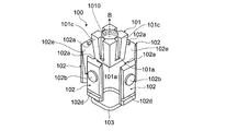
- FIG. 3 is a view showing the joint 100
- FIG. 4 is an exploded view of the joint 100 shown in FIG.
- the joint 100 includes a block 101, four plates 102 surrounding the block 101, and an O-ring 103 that presses the four plates 102 against the block 101.
- the block 101 and the plate 102 are members made of a steel material mainly composed of iron
- the O-ring 103 is a rubber member.
- the plate 102 will be described as a member made of a steel material mainly composed of iron.
- an aluminum alloy or a resin is used in addition to the steel material mainly composed of iron. It may be adopted.
- the “engagement body” in the basic form of the connector and the frame structure described above may be an assembly of a plurality of members or a single member, but “the engagement body is composed of a plurality of plates.
- the application form “is” is suitable. According to this preferred application mode, since the “fixing member” is inserted between the plurality of plates, the plates spread smoothly and engage with the “engagement portion”, so that the joining is realized smoothly.
- the block 101 corresponds to an example of the fixing member in the basic form of the joint and the basic form of the frame structure
- the combination of the four plates 102 is the basic form and the frame of the joint.
- the four plates 102 correspond to an example of “a plurality of plates” in the application mode described above.
- the direction in which the joint 100 is relatively inserted with respect to the pipe 10 extending in the vertical direction in FIG. 2 is represented by an upward arrow B in FIG. 4.
- the four block side surfaces 101c that contact the four plates 102 are inclined obliquely with respect to the insertion direction indicated by the arrow B.
- the block 101 as a whole has a quadrangular truncated pyramid shape that tapers in a direction opposite to the insertion direction (downward direction in the figure).
- the tapered shape is said to be a tapered shape
- the shape of the truncated pyramid that is tapered in the downward direction as described above is the tapered shape in the basic form of the joint and the basic form of the frame structure described above. It corresponds to an example.
- the shape of the truncated pyramid other than the square truncated pyramid is not limited to that of the block 101 having the truncated pyramid shape as described above.
- the block 101 may be the same, or the truncated cone-shaped block 101 may be used.
- Each of the four block side surfaces 101c of the block 101 is provided with a groove portion 101a extending in parallel with the insertion direction.
- the four plates 102 are provided with convex portions 102a that fit into the groove portions 101a. When the block 101 comes into contact with the four plates 102, the convex portions 102a of the plates 102 are It fits in each groove 101a of the block 101.
- the engaging body is provided with a convex portion on a surface that contacts the fixing member, and the fixing member includes the convex portion and
- the application mode that “a concave portion to be fitted” is provided is preferable.
- the “concave portion” is formed in, for example, a groove shape so as not to prevent insertion of the “fixing member” for expanding the “engaging body”.
- the movement direction of the “engagement body” is restricted by the fitting of the “convex portion” and the “concave portion”, and the “engaging portion” is surely Will be engaged.
- Each groove 101a of the block 101 corresponds to an example of a recess in this application mode
- the projection 102a of the plate 102 corresponds to an example of a projection in this application mode.
- the block 101 is formed with a through hole 1010 penetrating the inside of the block 101 in the vertical direction of FIG.
- a spiral thread groove is formed on the wall surface of the through hole 1010.
- the spiral screw portion formed on the side surface of the bolt main body 20a in FIG. 2 rotates the bolt 20 with the insertion direction of the bolt 20 as the rotation axis. Fit into the above thread groove.
- the screw portion on the side surface of the bolt main body portion 20a is fitted in the screw groove on the wall surface of the through hole 1010 of the block 101 as the bolt 20 rotates, so that the block 101 and the bolt 20 described above in FIG. A strong bond between is realized.
- the fixing member is fastened at one end to a fastening member inserted into an opening provided in the second frame among the plurality of frames.
- fastening means tightening by being moved by a hand or a tool (that is, “fastening operation”), and thus “fastening member” is connected to “fastening portion” by some physical structure, This means that the “fastening portion” and the “fixing member” can be pulled to the “second frame” by the “fastening operation”.
- the “fastening member” is inserted into the “opening portion” and one end is fastened to the “fastening portion”, and the other end with respect to the one end is caught in the “second frame” side in some form.
- the bolt 20 is an example of a fastening member in the above-described application mode, and a portion provided with the through hole 1010 of the block 101 functions as an example of a fastening portion for the fastening member.
- a bolt-nut mechanism that is fastened by screw engagement can be applied to the “fastening member” and the “fastening portion”.
- a mechanism or a mechanism that is fastened by catching between a gear and a claw can be applied. According to such a preferred application mode, the frames can be easily and reliably joined by the fastening operation.
- FIG. 5 is a bottom view of the joint 100 when the joint 100 shown in FIG. 3 is viewed from below in FIG. 3, and
- FIG. 6 is a cross-sectional view of the joint 100 shown in FIG. 3 in a plane along the vertical direction of FIG. FIG.
- the four plates 102 are arranged so as to surround the center O with the adjacent plates 102 in contact with the adjacent plate contact surfaces 102 c.
- a substantially circular opening centered on the center O is formed on the bottom surface of the joint 100.
- this opening is an opening into which the bolt 20 is inserted so that the joint 100 is fastened to the bolt 20 of FIG.
- the four plates 102 form a quadrangular frustum-shaped space into which the block 101 is inserted, and have a substantially quadrangular frustum-shaped cylinder shape surrounding the space.
- the four plates 102 arranged as described above are tightened from the outside by O-rings 103 surrounding the four plates 102 as shown in FIG.
- O-rings 103 surrounding the four plates 102 as shown in FIG.
- the shape of FIG. 5 in which the four plates 102 surround the center O with the adjacent plate contact surfaces 102c in contact with each other is firmly held.
- an O-ring fixing groove 102d shown in FIG. 4 is provided in a portion of the four plates 102 in contact with the O-ring 103.
- the O-ring 103 By fitting the O-ring 103 into the O-ring fixing groove 102d, The O-ring 103 is prevented from shifting in the vertical direction in the figure, and the state where the four plates 102 are in contact with each other at the adjacent plate contact surface 102c as shown in FIG. 5 is maintained.
- the “engagement body” is an aggregate of a plurality of plates
- the “predetermined shape” is a shape that forms a space in which the “fixing member” is inserted, and is a shape that surrounds the space with a plurality of plates.
- the O-ring 103 described above corresponds to an example of the holding member.
- FIG. 6 shows a cross section of the joint 100 in a plane extending in the lateral direction of FIG. 5 passing through the center O of FIG.
- FIG. 6 shows a state in which the convex portion 102a of the plate 102 is fitted into the groove portion 101a of the block 101 within the dotted circle in this figure.
- the convex part 102a is caught by the terminal part 1010a of the groove part 101a of the block 101, and therefore, the block 101 is prevented from shifting upward from the state shown in FIG. .
- This terminal portion 1010a corresponds to an example of the “drop-off prevention portion”.
- the block 101 cannot move upward as compared with the state shown in FIG. 6, but can move downward, and the convex portion 102 a of the plate 102 remains along the groove portion 101 a of the block 101.
- the right plate 102 of FIG. receives a force pushed away from the block 101 in the left direction.
- FIG. 6 In the above description of FIG. 6, the left and right two plates 102 in FIG. 6 among the four plates 102 in FIG. 4 have been described, but the front side and the back side of the block 101 in FIG. In FIG. 6, there is a plate 102 (not shown), and when the block 101 moves downward from the state shown in FIG. 6, these plates 102 also receive a force pushed away from the block 101.
- the engaging body has a tapered shape corresponding to the tapered shape of the fixing member formed on the contact surface with the fixing member”.
- the application form is suitable.
- “the taper shape is formed” means that the “contact surfaces” form a taper shape
- “the taper shape corresponding to the taper shape of the fixing member” means “ It means that the angle between the “contact surfaces” is the same as the taper angle in the taper shape of the “fixing member”. According to such an application mode, the “fixing member” is brought into contact with the entire “abutting surface” to realize strong bonding.
- the left and right plates 102 in FIG. 6 each have a block abutting surface 102 e that abuts the block 101, which is inclined with respect to the vertical direction in FIG. 6 in accordance with the taper shape of the block 101. The situation is shown.
- FIG. 7 is a cross-sectional view showing a state when the joint 100 of FIG. 2 is inserted into the pipe 10 extending in the vertical direction of FIG.
- FIG. 7 shows the same cross section as that of FIG. 6 with respect to the cross section of the joint 100, and FIG. 7 also shows the cross section of the pipe 10 extending in the longitudinal direction of FIG. 2 into which the joint 100 is inserted. Yes.
- the plate 102 is provided with a protruding portion 102b protruding toward the pipe 10 in FIG. 7 on the surface (front surface) opposite to the surface in contact with the block 101.
- the protruding portion 102b When viewed from the front surface of 102, it has a disk-like shape as shown in the protrusion 102b of FIG.
- a joint fixing opening 10b is provided on the side surface of the pipe 10, and the joint fixing opening 10b has the same size as the protrusion 102b. It is a disk-shaped opening. Further, the positions (heights) of the protrusions 102b and the joint fixing opening 10b are aligned at the lower end of the joint 100 and the lower end of the pipe 10 as shown in FIG.
- FIG. 8 is a view showing a state in which the two pipes 10 and 10 ′ of FIG. 2 are joined by the joint 100 and the bolt 20.
- the bolt 20 passes through the second insertion port 10 a ′.
- the bolt body 20 of the bolt 20 is inserted into the circular opening shown in FIG. 5 formed by the four plates 102 of the joint 100.
- the bolt 20 is tightened (the bolt 20 rotates with the insertion direction of the bolt 20 as a rotation axis), so that the screw portion on the side surface of the front end portion (upper end portion in this figure) of the bolt main body portion 20a is blocked.
- 101 begins to fit into the thread groove on the wall surface of the through-hole 1010, whereby the entire bolt 20 moves upward in the figure.
- the movement of the bolt 20 continues until the bolt head portion 20a 'reaches the first insertion port 10a.
- the bolt 20 can no longer move upward in the figure.
- the block 101 is now moved to the bolt 20 side. The downward movement is started so as to be attracted.
- Part (b) of FIG. 8 shows a state when the block 101 starts to move downward by the rotation of the bolt 20.
- the four plates 102 are pressed toward the wall surface of the upper pipe 10 in the figure by the taper shape of the block 101 and the plate 102 described above in FIG. Go. Due to this pressing force, the protruding portion 102b of each plate 102 is pushed into the joint fixing opening 10b of the upper pipe 10. Further, when the four plates 102 are pressed toward the wall surface of the upper pipe 10 in the figure, the O-ring 103 is crushed between the four plates 102 and the wall surface of the upper pipe 10. And pushed into the O-ring fixing groove 102d.
- Part (c) of Fig. 8 shows a state in which the protruding portion 102b of each plate 102 is completely fitted into the joint fixing opening 10b of the upper pipe 10.
- the protrusions 102 b of the plates 102 are fitted into the joint fixing openings 10 b of the upper pipe 10, so that the joint 100 is made of the part (c) of FIG. 8.
- the joint 100 cannot be moved in the vertical direction, and the joint 100 is firmly fixed to the upper pipe 10.
- the O-ring 103 is completely pushed into the O-ring fixing groove 102d.
- the block 101 corresponds to an example of a fixing member in the basic form of the connector and the basic form of the frame structure
- the combination of the four plates 102 is the above-described connector.
- This corresponds to an example of the engaging body in the basic form and the basic form of the frame structure.
- the joint fixing opening 10b corresponds to an example of the engaging portion in the basic form of the connector and the basic form of the frame structure. That is, in the present embodiment, as an engagement method between the “engagement body” and the “engagement portion”, a method is employed in which the “engagement body” having the protrusion is fitted into the “engagement portion” having the opening.
- the joint 100 is inserted into the upper pipe 10 in FIG. 8, and the bolt 20 is inserted into the lower pipe 10 ′.
- the two pipes 10 and 10 ' can be easily joined.
- the joint 100 and the bolt 20 are accommodated in the pipes 10 and 10 ', enlargement of the joint portion is suppressed.
- the joints 100 are firmly fixed to the upper pipe 10 by fitting the protrusions 102b of the respective plates 102 into the joint fixing openings 10b of the upper pipe 10 in FIG.
- the joint can be fixed to the pipe.
- each plate 102 is pressed against the wall surface of the pipe, whereby the frictional force between each plate 102 and the wall surface of the pipe increases, and this joint is fixed to the upper pipe by this frictional force. Is done.
- each plate 102 to be pressed against the wall surface of the upper pipe 10
- the block 101 rotates around the bolt 20. May move downward.
- the pipes 10 and 10 ′ to be joined are square pipes having a hollow inside and a square cross section.
- a frame is used in each of the basic forms of the joining tool and the frame structure described above.
- a square pipe having a cross section other than a square or a cylindrical pipe may be employed in each of the basic forms of the joining tool and the frame structure described above.
- the inner wall of the upper pipe 10 in FIG. 8 that contacts the joint 100 is also tapered to increase the frictional force between the joint 100 and the upper pipe 10 in FIG. 8 may be devised so as to be easily fixed to the upper pipe 10.
- the block 101 is provided with the through hole 1010 penetrating the block 101 in order to fasten the bolt main body portion 20a.
- the hole for fastening the bolt body 20a Any hole having an opening on the side into which the portion 20 a is inserted may be used, and the hole is not necessarily a through hole penetrating the block 101.
Landscapes
- Engineering & Computer Science (AREA)
- General Engineering & Computer Science (AREA)
- Mechanical Engineering (AREA)
- Mutual Connection Of Rods And Tubes (AREA)
Abstract
La présente invention concerne un outil d'assemblage destiné à assembler des armatures les unes aux autres. Ledit outil comprend un corps d'accouplement qui comprend des éléments d'accouplement insérés dans la première armature parmi une pluralité d'armatures, au moyen des parties d'accouplement de la première armature. Un élément de fixation est inséré dans l'espace formé par le corps d'accouplement et a une forme conique afin de pousser et d'allonger le corps d'accouplement. La présente invention concerne en outre une structure d'armature qui comprend une première armature, une seconde armature reliée à la première armature et le dispositif d'assemblage pour coupler la première armature à la seconde armature.
Priority Applications (1)
| Application Number | Priority Date | Filing Date | Title |
|---|---|---|---|
| PCT/JP2008/058207 WO2009133601A1 (fr) | 2008-04-28 | 2008-04-28 | Outil d’assemblage et structure d’armature |
Applications Claiming Priority (1)
| Application Number | Priority Date | Filing Date | Title |
|---|---|---|---|
| PCT/JP2008/058207 WO2009133601A1 (fr) | 2008-04-28 | 2008-04-28 | Outil d’assemblage et structure d’armature |
Publications (1)
| Publication Number | Publication Date |
|---|---|
| WO2009133601A1 true WO2009133601A1 (fr) | 2009-11-05 |
Family
ID=41254832
Family Applications (1)
| Application Number | Title | Priority Date | Filing Date |
|---|---|---|---|
| PCT/JP2008/058207 Ceased WO2009133601A1 (fr) | 2008-04-28 | 2008-04-28 | Outil d’assemblage et structure d’armature |
Country Status (1)
| Country | Link |
|---|---|
| WO (1) | WO2009133601A1 (fr) |
Cited By (3)
| Publication number | Priority date | Publication date | Assignee | Title |
|---|---|---|---|---|
| US20160010675A1 (en) * | 2014-07-11 | 2016-01-14 | Maxplus Industries Co., Ltd | Connection device for tubes |
| CN108302104A (zh) * | 2018-02-09 | 2018-07-20 | 宁波积家创意家居设计有限公司 | 一种用于连接方管的膨胀扣 |
| US20240240616A1 (en) * | 2021-05-07 | 2024-07-18 | Napkin Innovation Limited | Connector |
Citations (2)
| Publication number | Priority date | Publication date | Assignee | Title |
|---|---|---|---|---|
| JPH0446211U (fr) * | 1990-08-23 | 1992-04-20 | ||
| JPH06200912A (ja) * | 1992-12-29 | 1994-07-19 | Takiron Co Ltd | パイプ接続具 |
-
2008
- 2008-04-28 WO PCT/JP2008/058207 patent/WO2009133601A1/fr not_active Ceased
Patent Citations (2)
| Publication number | Priority date | Publication date | Assignee | Title |
|---|---|---|---|---|
| JPH0446211U (fr) * | 1990-08-23 | 1992-04-20 | ||
| JPH06200912A (ja) * | 1992-12-29 | 1994-07-19 | Takiron Co Ltd | パイプ接続具 |
Cited By (4)
| Publication number | Priority date | Publication date | Assignee | Title |
|---|---|---|---|---|
| US20160010675A1 (en) * | 2014-07-11 | 2016-01-14 | Maxplus Industries Co., Ltd | Connection device for tubes |
| CN108302104A (zh) * | 2018-02-09 | 2018-07-20 | 宁波积家创意家居设计有限公司 | 一种用于连接方管的膨胀扣 |
| CN108302104B (zh) * | 2018-02-09 | 2024-04-09 | 宁波积家创意家居设计有限公司 | 一种用于连接方管的膨胀扣 |
| US20240240616A1 (en) * | 2021-05-07 | 2024-07-18 | Napkin Innovation Limited | Connector |
Similar Documents
| Publication | Publication Date | Title |
|---|---|---|
| US7594788B2 (en) | Clinch/broach connector | |
| KR101926130B1 (ko) | 원터치식 철근 커플러 | |
| KR19980070144A (ko) | 클린치형 고정구 부재 | |
| US7484919B2 (en) | Fastener assembly | |
| KR102581591B1 (ko) | 관 연결구조 및 이를 이용하는 phc 파일 구조체 | |
| WO2009133601A1 (fr) | Outil d’assemblage et structure d’armature | |
| JP2003171980A (ja) | 鉄骨柱の接合構造 | |
| JP7010429B2 (ja) | ブラインドボルト | |
| JP2017145885A (ja) | 接合部の補強治具および接合部の補強構造 | |
| KR101807562B1 (ko) | 철근 이음장치 | |
| JP2001304210A (ja) | 杆体継合金具 | |
| JP3054915B2 (ja) | 柱と柱の接合構造 | |
| JP6910612B2 (ja) | 接合部補強構造 | |
| JP6080361B2 (ja) | 接合部構造 | |
| JP2017020540A (ja) | 鋼材のボルト接合方法 | |
| JP3898700B2 (ja) | 制震用油圧ダンパ | |
| JP3054905B2 (ja) | 柱と柱の接合構造 | |
| JP6072549B2 (ja) | 締結座金装置 | |
| JP7216407B2 (ja) | 管継手構造 | |
| JP3739367B2 (ja) | 鉄骨材の連結機構 | |
| JP2001262700A (ja) | 柱と柱の接合構造 | |
| JP6747678B2 (ja) | 接合部補強構造 | |
| KR20190003135A (ko) | 세 방향 또는 네 방향 파이프 체결용 클램프 | |
| JP2000329118A (ja) | 杭の接合構造 | |
| JPH11311095A (ja) | 継手金具 |
Legal Events
| Date | Code | Title | Description |
|---|---|---|---|
| 121 | Ep: the epo has been informed by wipo that ep was designated in this application |
Ref document number: 08752217 Country of ref document: EP Kind code of ref document: A1 |
|
| NENP | Non-entry into the national phase |
Ref country code: DE |
|
| 122 | Ep: pct application non-entry in european phase |
Ref document number: 08752217 Country of ref document: EP Kind code of ref document: A1 |
|
| NENP | Non-entry into the national phase |
Ref country code: JP |