WO2009133684A1 - 筒状編地の編成方法および筒状編地 - Google Patents
筒状編地の編成方法および筒状編地 Download PDFInfo
- Publication number
- WO2009133684A1 WO2009133684A1 PCT/JP2009/001893 JP2009001893W WO2009133684A1 WO 2009133684 A1 WO2009133684 A1 WO 2009133684A1 JP 2009001893 W JP2009001893 W JP 2009001893W WO 2009133684 A1 WO2009133684 A1 WO 2009133684A1
- Authority
- WO
- WIPO (PCT)
- Prior art keywords
- knitting
- yarn
- knitted fabric
- yarn feeding
- feeding member
- Prior art date
- Legal status (The legal status is an assumption and is not a legal conclusion. Google has not performed a legal analysis and makes no representation as to the accuracy of the status listed.)
- Ceased
Links
Images


Classifications
-
- D—TEXTILES; PAPER
- D04—BRAIDING; LACE-MAKING; KNITTING; TRIMMINGS; NON-WOVEN FABRICS
- D04B—KNITTING
- D04B1/00—Weft knitting processes for the production of fabrics or articles not dependent on the use of particular machines; Fabrics or articles defined by such processes
- D04B1/10—Patterned fabrics or articles
- D04B1/102—Patterned fabrics or articles with stitch pattern
- D04B1/106—Patterned fabrics or articles with stitch pattern at a selvedge, e.g. hems or turned welts
-
- D—TEXTILES; PAPER
- D04—BRAIDING; LACE-MAKING; KNITTING; TRIMMINGS; NON-WOVEN FABRICS
- D04B—KNITTING
- D04B1/00—Weft knitting processes for the production of fabrics or articles not dependent on the use of particular machines; Fabrics or articles defined by such processes
- D04B1/22—Weft knitting processes for the production of fabrics or articles not dependent on the use of particular machines; Fabrics or articles defined by such processes specially adapted for knitting goods of particular configuration
-
- D—TEXTILES; PAPER
- D04—BRAIDING; LACE-MAKING; KNITTING; TRIMMINGS; NON-WOVEN FABRICS
- D04B—KNITTING
- D04B7/00—Flat-bed knitting machines with independently-movable needles
- D04B7/30—Flat-bed knitting machines with independently-movable needles specially adapted for knitting goods of particular configuration
- D04B7/32—Flat-bed knitting machines with independently-movable needles specially adapted for knitting goods of particular configuration tubular goods
Definitions
- the present invention relates to a method of knitting a tubular knitted fabric by double system knitting with a flat knitting machine, and a tubular knitted fabric knitted by this method.
- a flat knitting machine includes at least a pair of front and back needle beds, a carriage that reciprocates on the needle beds, and a plurality of yarn path rails that are arranged above the needle beds in parallel in a direction perpendicular to the longitudinal direction of the needle beds.
- the carriage has a plurality of cam systems for causing the knitting needles arranged on the needle bed to perform the knitting operation.
- a yarn supplying member is slidably attached to each yarn path rail in a direction parallel to the longitudinal direction of the needle bed.
- One type of knitting technology using a flat knitting machine is double system knitting (for example, Patent Document 1).
- double system knitting a plurality of yarn supplying members are entrained by a carriage, and yarns are supplied from each yarn supplying member to each of the knitting needles driven by the preceding and following cam systems of the carriage. Thereby, knitting for two courses is performed by moving the carriage in one direction.
- FIG. 5A illustrates a case where a tubular knitted fabric is knitted counterclockwise (in the direction of a thin arrow in the figure).
- the lower side of the paper is the front needle bed
- the front knitted fabric portion FF of the tubular knitted fabric is knitted on the front needle bed
- the upper side of the paper is the rear needle bed
- the rear needle The rear knitted fabric portion BF is knitted on the floor.
- FIG. 5B is a loop diagram in which the portion indicated by the two-dot chain line in FIG. 5A is viewed from the direction of the white arrow.
- the yarn supplying member 5 is a preceding yarn supplying member and the yarn supplying member 6 is a subsequent yarn supplying member, the crossing problem described above occurs at the right end in the knitting width direction.
- 5 shows an example in which two knitting yarns are fed from one yarn feeding member. Of course, the same problem occurs even when one knitting yarn is fed from one yarn feeding member. Arise.
- the present invention has been made in view of the above circumstances.
- the purpose of the present invention is at the boundary between the front knitted fabric portion and the rear knitted fabric portion even when knitting the knitted fabric into a tubular shape by double system knitting.
- An object of the present invention is to provide a knitting method of a tubular knitted fabric in which no large hole is generated and a tubular knitted fabric knitted by this knitting method.
- the knitting method of the tubular knitted fabric of the present invention has at least a pair of front and back needle beds, and is configured to cause the knitting needles on the needle beds to perform knitting operations by a plurality of cam systems provided in a carriage that reciprocates on the needle beds.
- a plurality of yarn feeding units that are reciprocally attached in a direction parallel to the longitudinal direction of the needle bed to each of a plurality of yarn path rails arranged in parallel to the direction perpendicular to the longitudinal direction of the needle bed above the needle bed
- the present invention relates to a knitting method of a tubular knitted fabric in which a knitting for two courses is performed by a preceding cam system and a following cam system by moving a carriage in one direction using a flat knitting machine including members.
- one of the front side is positioned on the back side of the front side yarn feeding member and the front side yarn feeding member.
- the yarn member is the back yarn supplying member and the yarn supplying member positioned between the front yarn supplying member and the back yarn supplying member is the middle yarn supplying member, the preceding cam system and the following cam system
- the knitting needle driven by either one of the cam systems is fed from the front side yarn feeding member and the back side yarn feeding member, and the knitting needle driven by the other cam system is fed by the middle side.
- the yarn is fed from the yarn member and knitted in a cylindrical shape.
- the knitting needle driven by the preceding cam system from the front side yarn feeding member and the back side yarn feeding member.
- the tubular knitted fabric of the present invention has at least a pair of front and rear needle beds, and is configured to cause the knitting needles on the needle bed to perform knitting operations by a plurality of cam systems provided in a carriage that reciprocates on the needle bed.
- a plurality of yarn supplying members that are reciprocally attached in a direction parallel to the longitudinal direction of the needle bed to each of a plurality of yarn path rails arranged in parallel to the direction perpendicular to the longitudinal direction of the needle bed above the needle bed Using a flat knitting machine including a front knitted fabric portion knitted by knitting for two courses with a preceding cam system and a following cam system by moving the carriage in one direction.
- a flat knitting machine including a front knitted fabric portion knitted by knitting for two courses with a preceding cam system and a following cam system by moving the carriage in one direction.
- the tubular knitted fabric is formed by alternately repeating a first knitting course composed of a plurality of knitting yarns and a second knitting course composed of one or more knitting yarns.
- the cylindrical knitted fabric of the present invention is a part of the plurality of knitting yarns constituting the sinker loop of the knitting yarn of the first knitting course at the boundary between the front knitted fabric portion and the rear knitted fabric portion.
- the knitting yarn crosses the sinker loop of the second knitting course adjacent to the first knitting course, and the remaining knitting yarn does not cross the sinker loop of the second knitting course.
- the knitting yarn from the front yarn supplying member and the middle knitted fabric are fed.
- the knitting yarns from the yarn member intersect the knitting yarn from the middle yarn feeding member and the knitting yarn from the back yarn feeding member do not intersect.
- the knitting yarn from the front and rear knitted fabric portions is switched, when the knitting yarn from the back side yarn feeding member and the knitting yarn from the middle side yarn feeding member intersect, the knitting yarn from the middle side yarn feeding member and the near side yarn feeding Knitting yarns from members do not intersect.
- yarn is fed from the near side yarn feeding member and the far side yarn feeding member by feeding yarn from the near side yarn feeding member and the far side yarn feeding member to the knitting needle driven by the preceding cam system.
- the first knitting course is formed before the second knitting course that receives yarn from the middle yarn supplying member.
- the middle side yarn is fed to one of the already formed knitting yarns from the near side yarn feeding member and the knitting yarn from the back side yarn feeding member. The knitting yarns from the members intersect to pull up the one knitting yarn to the second knitting course side.
- the shape of the sinker loop of the boundary portion X derived from the knitting yarn from the middle yarn supplying member is not greatly deformed with respect to the shape of the sinker loop other than the boundary portion X in the same knitting course (described later). (See the sinker loop derived from the yarn supplying member 5 in FIG. 1B).
- the knitting yarn from the middle yarn supplying member does not cross any one of the other knitting yarns, and the other knitting yarn maintains the state when formed. That is, in any knitting course of the knitted fabric, there are sinker loops having the same height in the knitted fabric, and the shapes of these sinker loops are also uniform, so that the knitted fabric looks good (see FIG. 1B). ). Also in this case, since the left and right boundary portions of the knitted fabric look almost the same, a knitted fabric having a balanced and beautiful finish can be obtained.
- (A) is explanatory drawing which shows the state of the yarn supplying member when knitting by the knitting method of the cylindrical knitted fabric described in the first embodiment.
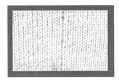
- (B) is the loop figure which looked at the boundary part of the front and back knitted fabric part in the side enclosed by the dotted line of (A) from the direction of the white arrow. 4 is a photograph of the vicinity of a boundary portion in the tubular knitted fabric described in the first embodiment.
- (A) is explanatory drawing which shows the state of the yarn supplying member when knitting by the knitting method of the tubular knitted fabric described in the second embodiment.
- (B) is the loop figure which looked at the boundary part of the front and back knitted fabric part in the side enclosed by the dotted line of (A) from the direction of the white arrow.
- FIG. 6 is a photograph of the vicinity of a boundary portion in the tubular knitted fabric described in the second embodiment.
- A is explanatory drawing which shows the state of a yarn supplying member when knitting with the conventional knitting method of a cylindrical knitted fabric.
- B is the loop figure which looked at the boundary part of the front and back knitted fabric part in the side enclosed by the dotted line of (A) from the direction of the white arrow. It is the photograph of the boundary part vicinity in the conventional cylindrical knitted fabric.
- the front knitted fabric is knitted on the front needle bed by double system knitting in which knitting for two courses is performed at a time by one forward or backward movement of the carriage provided in the flat knitting machine.
- a tubular knitted fabric composed of a portion and a rear knitted fabric portion knitted on the rear needle bed is knitted.
- the tubular knitted fabric of the present invention includes not only a tubular shape in which the front and rear knitted fabric portions are completely continuous (for example, a sweater) but also a material in which a part of the tube is not continuous (for example, a cardigan).
- the flat knitting machine is a flat knitting machine that has a pair of front and back needle beds extending in the left-right direction and facing each other in the front-rear direction.
- a flat knitting machine a two-bed flat knitting machine having a front needle bed and a rear needle bed, or a four-bed flat knitting machine having two needle beds facing further above the front and back needle beds. And so on.
- the flat knitting machine to be used includes a plurality of yarn path rails arranged in parallel in a direction perpendicular to the longitudinal direction of the needle bed above the needle bed, regardless of how many needle beds are provided.
- Each yarn path rail is slidably attached to the yarn path rail, and these yarn supply members can reciprocate in a direction parallel to the longitudinal direction of the needle bed.
- FIG. 1 and FIG. 3 used for description of Embodiments 1 and 2 to be described later, only three yarn feeding members 4, yarn feeding members 5, and yarn feeding members 6 are shown.
- the positional relationship of these yarn supply members 4 to 6 is such that the yarn supply member 4 (front side yarn supply member) is the frontmost side when viewed from the front side of the flat knitting machine, and the yarn supply member 6 (back side supply) is the rearmost side.
- the yarn member) is in a positional relationship in which the yarn feeding member 5 (middle yarn feeding member) is disposed between the yarn feeding member 4 and the yarn feeding member 6.
- the flat knitting machine includes a carriage on which a plurality of cam systems for driving the knitting needles of the needle bed are mounted.
- double system knitting is performed by using two of the plurality of cam systems for forming the stitches. If three or more cam systems are provided, two may be used for forming a stitch and the remaining may be used for transferring or the like.
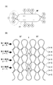
- FIG. 1 (A) is a diagram showing the positional relationship between the yarn feeding members 4, 5, and 6 during knitting.
- the thin arrows in this figure are the moving directions of the yarn supplying members 4, 5 and 6 (the same as the moving direction of the carriage), and the front needle bed on the lower side of the paper as the yarn supplying members 4, 5 and 6 move.
- the front knitted fabric portion FF is knitted, and the rear knitted fabric portion BF is knitted on the rear needle bed on the upper side of the drawing.
- FIG. 1 (B) is a loop diagram of the portion indicated by the two-dot chain line in FIG. 1 (A) as seen from the direction of the white arrow, and shows the front knitted fabric portion FF and the rear knitted fabric portion BF.
- the boundary part X is shown with a dashed-dotted line. Note that FIG. 3 used for explaining the second embodiment to be described later also has the same view.
- one knitting yarn is fed from each of the yarn feeding members 4 and 6 to the knitting needle driven by the preceding cam system.
- two knitting yarns are fed from the yarn feeding member 5 to the knitting needles driven by the following cam system.
- the yarn supplying members 4 and 6 are caused to travel so as to precede the yarn supplying member 5.
- the order of the yarn supplying member 4 and the yarn supplying member 6 in the carriage is not particularly limited, and may be completely the same as long as the tip portions of the yarn supplying members 4 and 6 do not interfere with each other.
- the thickness of the knitted fabric becomes uniform, and the knitting yarns knitted with both cam systems have the same color. This will improve the appearance of the knitted fabric. Therefore, in the present embodiment, one yarn of the same color is fed from each of the yarn feeding members 4 and 6, and two yarns of the same color are fed from the yarn feeding member 5.
- a yarn supplying member 5 and a yarn supplying member 5 '(not shown) different from the yarn supplying member 5 are used.
- Each knitting yarn may be fed one by one.
- the yarn supplying member 5 ′ is used on the back side of the yarn supplying member 4 and on the front side of the yarn supplying member 6.
- the first knitting course including the two knitting yarns supplied from the yarn supplying members 4 and 6 is supplied from the yarn supplying member 5. It is formed before the second knitting course consisting of two knitting yarns to be knitted.
- the knitting width direction left end portion (portion surrounded by a two-dot chain line in FIG. 1A) where the knitting of the rear knitted fabric portion BF shifts to the knitting of the front knitted fabric portion FF the rear knitted fabric portion
- the knitting yarn of the yarn supplying member 5 intersects the knitting yarn of the yarn supplying member 6.
- the knitting yarn of the yarn supplying member 5 pulls up the knitting yarn of the yarn supplying member 6.
- the knitting yarn of the yarn supplying member 4 does not intersect with the knitting yarn of the yarn supplying member 5, when the knitting of the rear knitted fabric portion BF is shifted to the knitting of the front knitted fabric portion FF, It is not pulled up by the knitting yarn.
- the state of the stitches at the boundary portion X between the front knitted fabric portion FF and the rear knitted fabric portion BF at the left end in the knitting width direction of the tubular knitted fabric knitted as described above is as shown in FIG. become.
- the sinker loop derived from the yarn supplying member 6 among the sinker loops of the first knitting course is the second knitting formed after the first knitting course. It is pulled up to the second knitting course side by hanging on the sinker loop (derived from the yarn supplying member 5) of the course.
- the shape of the sinker loop derived from the yarn supplying member 5 is substantially the same as the shape of a normal sinker loop (sinker loop other than the boundary portion X).
- the sinker loops at the boundary portion X are substantially the same shape and the same height as the sinker loops other than the boundary portion X.
- the sinker loop derived from the yarn supplying member 4 does not intersect the sinker loop of the second knitting course at the boundary portion X, it is formed without being pulled up at all on the second knitting course side. (A state in which the second knitting course formed immediately before the first knitting course is engaged with a pair of stitches sandwiching the boundary X).
- the knitting yarn of the yarn supplying member 4 intersects with the knitting yarn of the yarn supplying member 5 and is pulled up by this knitting yarn. It does not intersect with the knitting yarn of the member 5 and is not pulled up by this knitting yarn. Therefore, no hole is generated in the boundary portion between the front and rear knitted fabric portions at the right end portion in the knitting width direction.
- the above-described boundary portion X at the left end portion in the knitting width direction and the boundary portion at the right end portion in the knitting width direction form a first knitting course that intersects the knitting yarn (derived from the yarn supplying member 5) forming the second knitting course.
- the knitting yarn is from the yarn supplying member 6 or from the yarn supplying member 4
- one of the two knitting yarns forming the first knitting course is pulled up, and the rest is It is the same in that it cannot be raised. Therefore, both the boundary portions in the knitted fabric have almost the same appearance, so that the knitted fabric having a beautiful finish with a balanced appearance is obtained.
- the knitting yarn from the middle yarn supplying member is supplied to the knitting in the subsequent cam system, but may be supplied to the knitting in the preceding cam system.
- the yarn is fed from the middle yarn feeding member to the knitting in the preceding cam system.
- the yarn feeding members 4 to 6 are arranged in this order from the front to the back of the flat knitting machine. Then, the carriage is moved in the left direction in the drawing to knitting the rear knitted fabric portion BF, and the carriage is moved in the right direction in the drawing in order to knitting the front knitted fabric portion FF.
- the second knitting course composed of two knitting yarns fed from the yarn feeding member 5 becomes the second knitting yarn composed of two knitting yarns fed from the yarn feeding members 4 and 6. It is formed before the one-course.
- the knitting width direction left end portion (a portion surrounded by a two-dot chain line in FIG. 3A) where the knitting of the rear knitted fabric portion BF shifts to the knitting of the front knitted fabric portion FF
- the knitting yarn of the yarn supplying member 4 intersects the knitting yarn of the yarn supplying member 5.
- the knitting yarn of the yarn supplying member 4 pulls up the two knitting yarns of the yarn supplying member 5.
- the knitting yarn of the yarn supplying member 4 is pulled down by the two knitting yarns of the yarn supplying member 5.
- the knitting yarn of the yarn supplying member 6 does not intersect with the knitting yarn of the yarn supplying member 5, it is not pulled down by the knitting yarn of the yarn supplying member 5.
- FIG. 3B shows the state of the stitches at the boundary X at the left end of the knitted tubular knitted fabric.
- the sinker loop derived from the yarn supplying member 4 among the sinker loops of the first knitting course is the second knitting course formed before the first knitting course.
- the sinker loop is pulled down to the second knitting course side.
- the sinker loop derived from the yarn supplying member 6 does not intersect the sinker loop of the second knitting course, and is not pulled down to the second knitting course at all.
- the sinker loop has the same shape as the sinker loop when knitting is performed, that is, the sinker loop having the same shape as the sinker loop at a position different from the boundary portion X in the same knitting course. More specifically, the sinker loop derived from the yarn supplying member 6 is in a state of being hooked on a pair of stitches sandwiching the boundary portion X in the second knitting course formed immediately before the first knitting course. It is in.
- the tubular knitted fabric knitting method of the present embodiment is the sinker of the knitting course (second knitting course) formed first at the boundary portion X between the front knitted fabric portion FF and the rear knitted fabric portion BF.
- the loop is pulled up and deformed by a sinker loop of a knitting course (first knitting course) formed later, which is the same as the conventional double system knitting in that a hole is formed in the knitted fabric.
- the non-intersecting sinker loop derived from the knitting yarn from the yarn supplying member 6 makes the hole generated at the boundary X very small. Actually, even when looking at a photograph (FIG.
- the knitting yarn of the yarn supplying member 6 intersects with the two knitting yarns from the yarn supplying member 5 and pulls up these knitting yarns. Does not cross the two knitting yarns from the yarn supplying member 5, and does not pull up these knitting yarns. That is, the right end portion in the knitting width direction also has the same appearance as the left end portion in the knitting width direction described above, so that it looks much better than the knitted fabric knitted by the conventional knitting method.
- the knitting method of the tubular knitted fabric of the present invention can be suitably used for double system knitting in which knitting for two courses can be performed by moving the carriage in one direction.
Landscapes
- Engineering & Computer Science (AREA)
- Textile Engineering (AREA)
- Knitting Of Fabric (AREA)
- Knitting Machines (AREA)
- Braiding, Manufacturing Of Bobbin-Net Or Lace, And Manufacturing Of Nets By Knotting (AREA)
Abstract
Description
以上説明した横編機を使用して、図1に示すような後側編地部BFと前側編地部FFとからなる筒状編地を編成する。図1(A)は、編成時の給糸部材4,5,6の位置関係を示す図である。この図における細い矢印は、給糸部材4,5,6の移動方向(キャリッジの移動方向と同じ)であり、給糸部材4,5,6の移動に伴って紙面下側の前針床で前側編地部FFが編成され、紙面上側の後針床で後側編地部BFが編成される。また、図1(B)は、図1(A)の二点鎖線で示す部分を白抜き矢印の方向から見たループ図であって、前側編地部FFと後側編地部BFとの境界部Xを一点鎖線で示す。なお、後述する実施形態2の説明に使用する図3も、図の見方は同じである。
実施形態1では、中側給糸部材からの編糸を、後行のカムシステムでの編成に給糸しているが、先行のカムシステムでの編成に給糸しても良い。以下、図3および図4を参照して、中側給糸部材から先行のカムシステムでの編成に給糸する場合を説明する。
FF 前側編地部
BF 後側編地部
X 前後の編地部の境界部
g 孔
Claims (3)
- 少なくとも前後一対の針床を有し、針床上を往復するキャリッジに備わる複数のカムシステムにより針床の編針に編成動作を行わせるように構成されると共に、針床の上方に針床の長手方向と直交する方向に並列される複数の糸道レールのそれぞれに対して、針床の長手方向に平行な方向に往復可能に取り付けられる複数の給糸部材を備える横編機を用いて、キャリッジの一方向への移動により先行のカムシステムと後行のカムシステムとで2コース分の編成を行う筒状編地の編成方法であって、
横編機に備わる給糸部材のうち、前面側の一つを手前側給糸部材、
手前側給糸部材よりも奥側に位置する給糸部材を奥側給糸部材、
手前側給糸部材と奥側給糸部材との間に位置する給糸部材を中側給糸部材としたときに、
先行のカムシステムと後行のカムシステムのいずれか一方のカムシステムで駆動される編針に対して手前側給糸部材と奥側給糸部材から給糸させると共に、
前記いずれか他方のカムシステムで駆動される編針に対して中側給糸部材から給糸させて筒状に編成を実施することを特徴とする筒状編地の編成方法。 - 先行のカムシステムで駆動される編針に対して手前側給糸部材と奥側給糸部材から給糸させることを特徴とする請求項1に記載の筒状編地の編成方法。
- 少なくとも前後一対の針床を有し、針床上を往復するキャリッジに備わる複数のカムシステムにより針床の編針に編成動作を行わせるように構成されると共に、針床の上方に針床の長手方向と直交する方向に並列される複数の糸道レールのそれぞれに対して、針床の長手方向に平行な方向に往復可能に取り付けられる複数の給糸部材を備える横編機を用いて、キャリッジの一方向への移動により先行のカムシステムと後行のカムシステムとで2コース分の編成を行うことにより編成される前後の編地部からなる筒状編地であって、
複数本の編糸からなる第1編成コースと、
1本以上の編糸からなる第2編成コースとが交互に繰り返されることで形成され、
前側編地部と後側編地部との境界部において、第1編成コースのシンカーループを構成する複数本の編糸のうち、一部の編糸が、第1編成コースに隣接する第2編成コースのシンカーループに交差し、残部の編糸が、第2編成コースのシンカーループに交差していないことを特徴とする筒状編地。
Priority Applications (3)
| Application Number | Priority Date | Filing Date | Title |
|---|---|---|---|
| CN2009801158768A CN102016146B (zh) | 2008-05-02 | 2009-04-24 | 筒状编织物的编织方法及筒状编织物 |
| JP2010510031A JP5514717B2 (ja) | 2008-05-02 | 2009-04-24 | 筒状編地の編成方法および筒状編地 |
| EP09738621.3A EP2290141B1 (en) | 2008-05-02 | 2009-04-24 | Method of knitting a tubular fabric and tubular fabric |
Applications Claiming Priority (2)
| Application Number | Priority Date | Filing Date | Title |
|---|---|---|---|
| JP2008120672 | 2008-05-02 | ||
| JP2008-120672 | 2008-05-02 |
Publications (1)
| Publication Number | Publication Date |
|---|---|
| WO2009133684A1 true WO2009133684A1 (ja) | 2009-11-05 |
Family
ID=41254909
Family Applications (1)
| Application Number | Title | Priority Date | Filing Date |
|---|---|---|---|
| PCT/JP2009/001893 Ceased WO2009133684A1 (ja) | 2008-05-02 | 2009-04-24 | 筒状編地の編成方法および筒状編地 |
Country Status (4)
| Country | Link |
|---|---|
| EP (1) | EP2290141B1 (ja) |
| JP (1) | JP5514717B2 (ja) |
| CN (1) | CN102016146B (ja) |
| WO (1) | WO2009133684A1 (ja) |
Cited By (3)
| Publication number | Priority date | Publication date | Assignee | Title |
|---|---|---|---|---|
| KR20220167239A (ko) * | 2021-06-11 | 2022-12-20 | 가부시키가이샤 시마세이키 세이사쿠쇼 | 니트웨어의 편성방법 및 횡편기의 캠시스템에 대한 편성 데이터의 할당장치 |
| JP7607516B2 (ja) | 2021-05-26 | 2024-12-27 | 株式会社島精機製作所 | 編地の編成方法 |
| JP7628059B2 (ja) | 2021-06-11 | 2025-02-07 | 株式会社島精機製作所 | 筒状パイル編地の編成方法および筒状パイル編地 |
Families Citing this family (4)
| Publication number | Priority date | Publication date | Assignee | Title |
|---|---|---|---|---|
| CN102975406B (zh) * | 2012-11-14 | 2015-11-11 | 广州誉发纺织科技有限公司 | 一种止滑织物 |
| JP6419489B2 (ja) * | 2014-08-26 | 2018-11-07 | キクロン株式会社 | ボディタオル |
| CN105220337B (zh) * | 2015-10-20 | 2017-03-08 | 珠海建轩服装有限公司 | 不规则形状毛织片及其制备方法 |
| CN108729002A (zh) * | 2018-08-23 | 2018-11-02 | 福建荣荣新材料股份有限公司 | 一体编织成型的立体织物及其编织方法 |
Citations (3)
| Publication number | Priority date | Publication date | Assignee | Title |
|---|---|---|---|---|
| JPH10266047A (ja) | 1997-03-26 | 1998-10-06 | Shima Seiki Mfg Ltd | 筒状編地の編成方法 |
| JP2000034654A (ja) * | 1998-07-15 | 2000-02-02 | Shima Seiki Mfg Ltd | リブ編みを含む両面編地の編成方法およびその編地 |
| WO2007099709A1 (ja) * | 2006-02-28 | 2007-09-07 | Shima Seiki Mfg., Ltd. | 筒状編地の編成方法および筒状編地 |
Family Cites Families (2)
| Publication number | Priority date | Publication date | Assignee | Title |
|---|---|---|---|---|
| DE19654027A1 (de) * | 1996-12-21 | 1998-06-25 | Stoll & Co H | Verfahren zur Herstellung eines schlauchförmigen Gestricks |
| JP4336307B2 (ja) * | 2004-12-28 | 2009-09-30 | 株式会社島精機製作所 | 二重の筒状編地の編成方法 |
-
2009
- 2009-04-24 EP EP09738621.3A patent/EP2290141B1/en not_active Not-in-force
- 2009-04-24 CN CN2009801158768A patent/CN102016146B/zh not_active Expired - Fee Related
- 2009-04-24 WO PCT/JP2009/001893 patent/WO2009133684A1/ja not_active Ceased
- 2009-04-24 JP JP2010510031A patent/JP5514717B2/ja not_active Expired - Fee Related
Patent Citations (3)
| Publication number | Priority date | Publication date | Assignee | Title |
|---|---|---|---|---|
| JPH10266047A (ja) | 1997-03-26 | 1998-10-06 | Shima Seiki Mfg Ltd | 筒状編地の編成方法 |
| JP2000034654A (ja) * | 1998-07-15 | 2000-02-02 | Shima Seiki Mfg Ltd | リブ編みを含む両面編地の編成方法およびその編地 |
| WO2007099709A1 (ja) * | 2006-02-28 | 2007-09-07 | Shima Seiki Mfg., Ltd. | 筒状編地の編成方法および筒状編地 |
Non-Patent Citations (1)
| Title |
|---|
| See also references of EP2290141A4 |
Cited By (4)
| Publication number | Priority date | Publication date | Assignee | Title |
|---|---|---|---|---|
| JP7607516B2 (ja) | 2021-05-26 | 2024-12-27 | 株式会社島精機製作所 | 編地の編成方法 |
| KR20220167239A (ko) * | 2021-06-11 | 2022-12-20 | 가부시키가이샤 시마세이키 세이사쿠쇼 | 니트웨어의 편성방법 및 횡편기의 캠시스템에 대한 편성 데이터의 할당장치 |
| KR102679576B1 (ko) | 2021-06-11 | 2024-06-27 | 가부시키가이샤 시마세이키 세이사쿠쇼 | 니트웨어의 편성방법 및 횡편기의 캠시스템에 대한 편성 데이터의 할당장치 |
| JP7628059B2 (ja) | 2021-06-11 | 2025-02-07 | 株式会社島精機製作所 | 筒状パイル編地の編成方法および筒状パイル編地 |
Also Published As
| Publication number | Publication date |
|---|---|
| EP2290141B1 (en) | 2015-09-30 |
| JPWO2009133684A1 (ja) | 2011-08-25 |
| EP2290141A1 (en) | 2011-03-02 |
| EP2290141A4 (en) | 2014-05-28 |
| JP5514717B2 (ja) | 2014-06-04 |
| CN102016146A (zh) | 2011-04-13 |
| CN102016146B (zh) | 2012-02-08 |
Similar Documents
| Publication | Publication Date | Title |
|---|---|---|
| JP5514717B2 (ja) | 筒状編地の編成方法および筒状編地 | |
| KR101387962B1 (ko) | 편성포의 편성방법 및 횡편성된 편성포 | |
| CN103031660B (zh) | 针织物的编织方法 | |
| JP3744797B2 (ja) | 編地およびその編成方法 | |
| CN101395313B (zh) | 筒状针织物的编织方法和筒状针织物 | |
| JP4180527B2 (ja) | プレーティングによるワイドリブ組織の編成方法 | |
| CN101395312B (zh) | 形成放针线圈的方法及在针织物的编织宽度方向端部的内侧形成放针线圈的针织物 | |
| KR101523498B1 (ko) | 편사의 풀림방지방법 | |
| KR101347648B1 (ko) | 편성포의 편성시작방법 | |
| JPWO2000063475A1 (ja) | 編地およびその編成方法 | |
| JP5479048B2 (ja) | 編地の編成方法、および編地 | |
| CN111058164A (zh) | 针织面料插入式拼接结构及其编织方法 | |
| KR101449913B1 (ko) | 편성포의 편성방법 | |
| CN102264963B (zh) | 内放针方法及针织物 | |
| JP2013014850A (ja) | 編地の編出し方法、および編地 | |
| JP2009270216A (ja) | 袋ジャカード組織部を有する編地の編成方法 | |
| CN115404587B (zh) | 编织物的编织方法 | |
| JP2022030303A (ja) | 編地の編成方法 | |
| JPH11315449A (ja) | 増目形成方法 | |
| JP2013036135A (ja) | 編地の編成方法、および編地 | |
| JP2000199157A (ja) | インタ―シャ編地における編糸の拘束方法 | |
| WO2022191048A1 (ja) | 筒状編地の編成方法 | |
| JP2002339202A (ja) | リブ編地の内増やし方法及び当該方法で内増やしされたリブ編地 |
Legal Events
| Date | Code | Title | Description |
|---|---|---|---|
| WWE | Wipo information: entry into national phase |
Ref document number: 200980115876.8 Country of ref document: CN |
|
| 121 | Ep: the epo has been informed by wipo that ep was designated in this application |
Ref document number: 09738621 Country of ref document: EP Kind code of ref document: A1 |
|
| ENP | Entry into the national phase |
Ref document number: 2010510031 Country of ref document: JP Kind code of ref document: A |
|
| NENP | Non-entry into the national phase |
Ref country code: DE |
|
| WWE | Wipo information: entry into national phase |
Ref document number: 2009738621 Country of ref document: EP |