WO2009133808A1 - 可搬式スクリーン装置及びそれに用いる伸縮支柱並びに操作具 - Google Patents
可搬式スクリーン装置及びそれに用いる伸縮支柱並びに操作具 Download PDFInfo
- Publication number
- WO2009133808A1 WO2009133808A1 PCT/JP2009/058123 JP2009058123W WO2009133808A1 WO 2009133808 A1 WO2009133808 A1 WO 2009133808A1 JP 2009058123 W JP2009058123 W JP 2009058123W WO 2009133808 A1 WO2009133808 A1 WO 2009133808A1
- Authority
- WO
- WIPO (PCT)
- Prior art keywords
- cylinder
- lock
- release
- wall
- tapered surface
- Prior art date
- Legal status (The legal status is an assumption and is not a legal conclusion. Google has not performed a legal analysis and makes no representation as to the accuracy of the status listed.)
- Ceased
Links
Images







Classifications
-
- G—PHYSICS
- G03—PHOTOGRAPHY; CINEMATOGRAPHY; ANALOGOUS TECHNIQUES USING WAVES OTHER THAN OPTICAL WAVES; ELECTROGRAPHY; HOLOGRAPHY
- G03B—APPARATUS OR ARRANGEMENTS FOR TAKING PHOTOGRAPHS OR FOR PROJECTING OR VIEWING THEM; APPARATUS OR ARRANGEMENTS EMPLOYING ANALOGOUS TECHNIQUES USING WAVES OTHER THAN OPTICAL WAVES; ACCESSORIES THEREFOR
- G03B21/00—Projectors or projection-type viewers; Accessories therefor
- G03B21/54—Accessories
- G03B21/56—Projection screens
- G03B21/58—Projection screens collapsible, e.g. foldable; of variable area
Definitions
- the present invention relates to a screen for enlarging and projecting a display image by a projection device such as a projector. .
- An image from a projector is generally enlarged and projected on a reflective screen.
- a reflective screen those that are used by being attached to a ceiling or a wall generally use a screen housed in a storage case by being pulled down electrically or manually as required.
- the hanging screen type screen device or the tripod stand type screen device is used by being hung in a predetermined place or placed on the floor.
- the present invention has been made in view of such demands and problems, and is a portable screen device that is small and light in weight, easy to handle, and capable of easily extending and retracting a support, and an extendable support and an operation tool used therefor. The purpose was to provide.
- a first portable screen device of the present invention includes a casing having an opening extending in a longitudinal direction, a spring roll rotatably attached to the casing, and the spring when stored.
- a screen that is wound around a roll and unwound from the opening when used, a top bar that serves as a lid that closes the opening when the screen is fixed, and an end that is supported by the casing.
- An extendable strut that holds the projected screen in a stretched state, and the strut includes at least a first tubular body, a second tubular body, and a third tubular body, wherein the first tubular body includes the first tubular body.
- the second cylinder slides on the third cylinder, and is a telescopic support column that is positioned in the order of the first cylinder, the second cylinder, and the third cylinder from the upper stage when extended. And slide the first cylinder A first locking portion that locks, a second locking portion that locks the slide of the second cylinder, an unlock lever provided at the upper end of the first cylinder, and an upper end that is movable up and down in the first cylinder A release bar that is pivotally supported by a lock release lever, a first lock release unit that is provided at a lower end portion of the release bar, and that releases the first lock portion; and a lower end portion of the release bar that includes the first lock A telescopic strut having a second lock release portion provided below the release portion and releasing the second lock portion is used.
- the first lock portion is disposed at the lower end portion of the first cylinder, and presses the inner wall of the second cylinder and locks the slide of the first cylinder by a frictional force with the inner wall.
- the second lock portion is disposed at the lower end of the second cylinder, presses the inner wall of the third cylinder, locks the slide of the second cylinder by a frictional force with the inner wall, and
- the first unlocking part releases the first locking part by releasing the pressing of the first locking part on the inner wall of the second cylinder, and the second unlocking part is the third cylinder of the second locking part. It is preferable to release the second lock portion by releasing the pressure on the inner wall of the body.
- the first lock portion is a sliding member that is partially fixed to the lower end portion of the first cylinder and has a tapered surface that is inclined toward the inner wall of the adjacent outer cylinder at least at a part of the circumferential surface.
- a stopper that is held between the tapered surface and the lower cylinder of each cylinder, and an elastic member that urges the stopper to abut against the tapered surface
- the second lock And a sliding member having a tapered surface that is partly fixed to the lower end portion of the second cylindrical body and has a tapered surface inclined toward the inner wall of the adjacent outer cylindrical body, and at least a part of the circumferential surface, It is preferable to have a stopper held between the lower cylinders of the cylinders and an elastic member that urges the stoppers so as to contact the tapered surface.
- the stopper has an inclined surface that comes into contact with the tapered surface.
- first lock portion is engaged with the first locking portion including a plurality of through holes provided in the longitudinal direction of the second cylinder, and the first locking portion provided at the lower end portion of the first cylinder.
- a first engaging portion that can be engaged, and the second locking portion includes a second locking portion including a plurality of through holes provided in a longitudinal direction of the third cylindrical body, and a lower end of the second cylindrical body.
- a second engaging portion that is engageable with the second locking portion, and the lower end of the release bar releases the engagement between the first locking portion and the first engaging portion. It is preferable to provide the 1 lock release part and the 2nd lock release part which cancels
- a handle portion is provided at the center portion of the top bar, while a hook portion is provided at a tip portion of the support column, and the handle portion is hooked on the hook portion.
- the hook portion is provided with the lock release lever so that the operation portion is located on the front side of the hook portion and is connected to the release bar, so that the lock release lever is pressed against the operation portion. It is preferable to raise the release bar in conjunction with it.
- one end of the support column is pivotally supported at the center of the side surface of the casing so as to be raised and lowered, and the unwound screen is held in a stretched state when standing.
- the lock mechanism has an engaging portion disposed on the top bar and an engaged portion disposed on the casing and engaged with the engaging portion.
- the engaging portion has a pair of engaging members disposed to face each other in the width direction of the top bar, while the engaged portions are respectively disposed on the opening edge portions facing the casing. It is preferable to have a pair of engaged members that engage with the members.
- the second portable screen device of the present invention is a casing having an opening extending in the longitudinal direction, a spring roll rotatably attached to the casing, and wound around the spring roll when housed.
- the screen that is unwound from the opening, one end of the screen is fixed, and when stored, the top bar that also serves as a lid that closes the opening, and one end is supported by the casing, the unrolled screen is in a stretched state
- An extendable strut that holds the expandable strut, and the strut is formed of a plurality of stages of cylinders. When the extension is extended, the struts are positioned in the order of at least the first cylinder and the second cylinder from the upper stage.
- the first lock release part is a lift of the release bar. The first lock portion is released in conjunction with the operation.
- the first lock portion is a part of which is fixed to a lower end portion of the first cylindrical body, and has a tapered surface inclined toward the inner wall of the adjacent outer cylindrical body at least in a part of the circumferential surface. It is preferable to have a member, a stopper held between the tapered surface and the lower cylinder of each cylinder, and an elastic member that urges the stopper so as to abut against the tapered surface.
- the first lock release portion is pivotally supported at the lower end of the release bar, and the other end releases the pressure on the inner wall of the second cylinder of the first lock portion in conjunction with the rise of the release bar. It is preferable to have a swinging member that swings, and the swinging member presses the stopper so as to release the contact with the tapered surface.
- a handle portion is provided at the center portion of the top bar, while a hook portion is provided at a tip portion of the support column, and the handle portion is hooked on the hook portion.
- the hook portion is provided with the lock release lever so that the operation portion is located on the front side of the hook portion and is connected to the release bar, so that the lock release lever is pressed against the operation portion. It is preferable to raise the release bar in conjunction with it.
- one end of the support column is pivotally supported at the center of the side surface of the casing so as to be raised and lowered, and the unwound screen is held in a stretched state when standing.
- the lock mechanism has an engaging portion disposed on the top bar and an engaged portion disposed on the casing and engaged with the engaging portion.
- the engaging portion has a pair of engaging members disposed to face each other in the width direction of the top bar, while the engaged portions are respectively disposed on the opening edge portions facing the casing. It is preferable to have a pair of engaged members that engage with the members.
- the third portable screen device of the present invention has a casing having an opening extending in the longitudinal direction, a spring roll rotatably attached to the casing, and is wound around the spring roll when housed.
- the screen that is unwound from the opening, one end of the screen is fixed, and when stored, the top bar that also serves as a lid that closes the opening, and one end is supported by the casing, the unrolled screen is in a stretched state
- One or more unlocking mechanisms that are provided at the lower end of the inner cylinder, and are released by the lock release lever provided at the upper end of the uppermost cylinder corresponding to the locking part.
- the upper end portion has a release bar pivotally supported by the lock release lever so as to move up and down in the cylinder, and the lower end portion of the release bar has the lock release portion.
- the lock portion is a sliding member that is partially fixed to the lower end portion of the cylindrical body other than the lowermost step and has a tapered surface that is inclined toward the inner wall of the adjacent outer cylindrical body at least at a part of the circumferential surface. And a stopper held between the tapered surface and the lower cylinder of each cylinder, and an elastic member that urges the stopper so as to abut against the tapered surface.
- the unlocking portion is pivoted so that one end is pivotally supported on the lower end portion of the releasing bar and the other end releases the pressure on the inner wall of the cylinder outside the locking portion in conjunction with the rising of the releasing bar. It is preferable to have a rocking member that moves.
- the rocking member has a rocking member that presses the stopper so as to release the contact with the tapered surface.
- the stopper has an inclined surface that comes into contact with the tapered surface.
- a handle portion is provided at the center portion of the top bar, while a hook portion is provided at a tip portion of the support column, and the handle portion is hooked on the hook portion.
- the hook portion is provided with the lock release lever so that the operation portion is located on the front side of the hook portion and is connected to the release bar, so that the lock release lever is pressed against the operation portion. It is preferable to raise the release bar in conjunction with it.
- one end of the support column is pivotally supported at the center of the side surface of the casing so as to be raised and lowered, and the unwound screen is held in a stretched state when standing.
- the lock mechanism has an engaging portion disposed on the top bar and an engaged portion disposed on the casing and engaged with the engaging portion.
- the engaging portion has a pair of engaging members disposed to face each other in the width direction of the top bar, while the engaged portions are respectively disposed on the opening edge portions facing the casing. It is preferable to have a pair of engaged members that engage with the members.
- the fourth portable screen device of the present invention is a casing having an opening extending in the longitudinal direction, a spring roll rotatably attached to the casing, and wound around the spring roll when stored.
- the screen that is unwound from the opening, one end of the screen is fixed, and when stored, the top bar that also serves as a lid that closes the opening, and one end is supported by the casing, the unrolled screen is in a stretched state
- the support column is formed of a plurality of stages of cylinders, and a lock part that locks the slides between the cylinders is provided at the lower end of each cylinder other than the lowest stage, A lock release lever is provided at the upper end of the column so that the upper end of the column is positioned above the top bar when the screen is extended. That.
- the upper end portion has a release bar pivotally supported by the lock release lever so as to be vertically movable in the cylinder, and the lock release portion is provided at the lower end portion of the release bar.
- the lock portion is a sliding member that is partially fixed to the lower end portion of the cylindrical body other than the lowermost step and has a tapered surface that is inclined toward the inner wall of the adjacent outer cylindrical body at least at a part of the circumferential surface. And a stopper held between the tapered surface and the lower cylinder of each cylinder, and an elastic member that urges the stopper so as to abut against the tapered surface.
- the unlocking portion is pivoted so that one end is pivotally supported on the lower end portion of the releasing bar and the other end releases the pressure on the inner wall of the cylinder outside the locking portion in conjunction with the rising of the releasing bar. It is preferable to have a rocking member that moves.
- the rocking member has a rocking member that presses the stopper so as to release the contact with the tapered surface.
- the stopper has an inclined surface that comes into contact with the tapered surface.
- a handle portion is provided at the center portion of the top bar, while a hook portion is provided at a tip portion of the support column, and the handle portion is hooked on the hook portion.
- the lock release lever is disposed on the hook portion so as to be positioned in front of the hook portion.
- one end of the support column is pivotally supported at the center of the side surface of the casing so as to be raised and lowered, and the unwound screen is held in a stretched state when standing.
- the lock mechanism has an engaging portion disposed on the top bar and an engaged portion disposed on the casing and engaged with the engaging portion.
- the engaging portion has a pair of engaging members disposed to face each other in the width direction of the top bar, while the engaged portions are respectively disposed on the opening edge portions facing the casing. It is preferable to have a pair of engaged members that engage with the members.
- the first telescopic strut of the present invention includes at least a first cylinder, a second cylinder, and a third cylinder, and the first cylinder slides in the second cylinder, and the second cylinder Is a telescopic strut that slides on the third cylindrical body and is positioned in the order of the first cylindrical body, the second cylindrical body, and the third cylindrical body from the upper stage when extended, and locks the slide of the first cylindrical body.
- a lock part a second lock part for locking the slide of the second cylinder, an unlock lever provided at the upper end of the first cylinder, and an unlock lever at the upper end so as to be movable up and down in the first cylinder
- a release bar that is pivotally supported at the lower end of the release bar, a first lock release part that releases the first lock part, and a lower end part of the release bar that is below the first lock release part.
- a second lock release unit that releases the second lock unit.
- the first lock portion is disposed at the lower end portion of the first cylinder, and presses the inner wall of the second cylinder and locks the slide of the first cylinder by a frictional force with the inner wall.
- the second lock portion is disposed at the lower end of the second cylinder, presses the inner wall of the third cylinder, locks the slide of the second cylinder by a frictional force with the inner wall, and
- the first unlocking part releases the first locking part by releasing the pressing of the first locking part on the inner wall of the second cylinder, and the second unlocking part is the third cylinder of the second locking part. It is preferable to release the second lock portion by releasing the pressure on the inner wall of the body.
- the first lock portion is a sliding member that is partially fixed to the lower end portion of the first cylinder and has a tapered surface that is inclined toward the inner wall of the adjacent outer cylinder at least at a part of the circumferential surface.
- a stopper that is held between the tapered surface and the lower cylinder of each cylinder, and an elastic member that urges the stopper to abut against the tapered surface
- the second lock And a sliding member having a tapered surface that is partly fixed to the lower end portion of the second cylindrical body and has a tapered surface inclined toward the inner wall of the adjacent outer cylindrical body, and at least a part of the circumferential surface, It is preferable to have a stopper held between the lower cylinders of the cylinders and an elastic member that urges the stoppers so as to contact the tapered surface.
- the stopper has an inclined surface that comes into contact with the tapered surface.
- first lock portion is engaged with the first locking portion including a plurality of through holes provided in the longitudinal direction of the second cylinder, and the first locking portion provided at the lower end portion of the first cylinder.
- a first engaging portion that can be engaged, and the second locking portion includes a second locking portion including a plurality of through holes provided in a longitudinal direction of the third cylindrical body, and a lower end of the second cylindrical body.
- a second engaging portion that is engageable with the second locking portion, and the lower end of the release bar releases the engagement between the first locking portion and the first engaging portion. It is preferable to provide the 1 lock release part and the 2nd lock release part which cancels
- the column is composed of four or more cylinders, and in the cylinder below the third cylinder, a lock portion is provided at the lower end portion of the previous cylinder, while the release bar corresponds to the lock portion. It is preferable to provide an unlocking part.
- the second telescopic support column of the present invention is composed of a plurality of stages of cylinders, and is an extension column that is positioned in the order of at least the first cylinder and the second cylinder from the upper stage when extended, and locks the slide of the first cylinder.
- a first unlocking part that releases the first locking part, and the first unlocking part releases the first locking part in conjunction with the rising of the release bar. It is characterized by.
- the first lock portion is a part of which is fixed to a lower end portion of the first cylindrical body, and has a tapered surface inclined toward the inner wall of the adjacent outer cylindrical body at least in a part of the circumferential surface. It is preferable to have a member, a stopper held between the tapered surface and the lower cylinder of each cylinder, and an elastic member that urges the stopper so as to abut against the tapered surface.
- the first lock release portion is pivotally supported at the lower end of the release bar, and the other end releases the pressure on the inner wall of the second cylinder of the first lock portion in conjunction with the rise of the release bar. It is preferable to have a swinging member that swings, and the swinging member presses the stopper so as to release the contact with the tapered surface.
- the third telescopic support column of the present invention is composed of a plurality of stages of cylinders, and includes one or more lock portions that lock the slides of the cylinders by frictional force with the inner walls of the adjacent outer cylinders.
- One or more lock release parts corresponding to the lock part are arranged at the lower end part so as to be movable up and down in the cylinder.
- the lock release lever provided at the upper end of the uppermost cylinder, and a release bar whose upper end is pivotally supported by the lock release lever so as to be movable up and down in the cylinder, the lower end of the release bar
- the part is preferably provided with a lock releasing part.
- the lock portion is a sliding member that is partially fixed to the lower end portion of the cylindrical body other than the lowermost step and has a tapered surface that is inclined toward the inner wall of the adjacent outer cylindrical body at least at a part of the circumferential surface. And a stopper held between the tapered surface and the lower cylinder of each cylinder, and an elastic member that urges the stopper so as to abut against the tapered surface.
- the unlocking portion is pivoted so that one end is pivotally supported on the lower end portion of the releasing bar and the other end releases the pressure on the inner wall of the cylinder outside the locking portion in conjunction with the rising of the releasing bar. It is preferable to have a rocking member that moves.
- the rocking member has a rocking member that presses the stopper so as to release the contact with the tapered surface.
- the stopper has an inclined surface that comes into contact with the tapered surface.
- the operation tool of the present invention is used in the first to fourth portable screen devices described above, and is provided with a handle portion at one end of the shaft portion and released by pressing a lock release lever at the other end.
- the release portion is disposed on the axis of the shaft portion and is in contact with the object to be released, and a pair of fixed protrusions provided on both sides of the movable protrusion and holding the movable protrusion. Part.
- a support column composed of a plurality of stages of cylinders
- a plurality of lock portions for locking slides between the cylinders are provided, and a plurality of lock release portions corresponding thereto are arranged so as to be vertically movable in the cylinder. Since it was made to do, the portable screen apparatus which can be expanded-contracted easily and can be hold
- the support column can be integrated with the casing and the support column can be raised and lowered, the screen device can be further reduced in size by laying the support column down during storage, and can be easily carried.
- the support column can be raised during use and the screen can be extended by extending the support column to the desired height, and when stored, the support column can be shortened and laid down, while the screen is rewound and the top bar is used to cover the opening. This is easy to handle. Further, since the top bar also serves as the lid of the casing, the lid is unnecessary, and the screen device can be further reduced in weight.
- FIG. 2 is a schematic perspective view showing a structure in a state where the screen is rewound in the portable screen device of FIG. 1. It is a model perspective view which shows the structure at the time of accommodation of the portable screen apparatus of FIG.
- FIG. 4 is an enlarged top view of the lock mechanism in FIG. 3.
- FIG. 5 is a schematic longitudinal sectional view taken along line VV in FIG. 3.
- FIG. 4 is a schematic longitudinal sectional view taken along line VI-VI in FIG. 3.
- FIG. FIG. 1 shows an example of a state when the portable screen device according to the present embodiment is used.
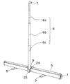
- the portable screen device P1 includes a casing 1, a spring roll (not shown) mounted in the casing, a screen 4 unwound from the opening 1a and extended between the top bar 5 and the spring roll, and the casing. 1 and a column 6 that is erected substantially at the center and holds the screen 4 at a predetermined height.
- the column 6 is a three-stage cylindrical body that is supported by a column attachment member 25 attached to the center of the casing 1 and that can slide and extend.
- pillar 6 has the hook part 7 which can be rotated horizontally at the front-end
- the screen 4 is suspended and hung.
- Reference numeral 9 denotes an engaging portion constituting a lock mechanism for fixing the top bar 5 to the casing 1 and engages with an engaged portion (not shown) disposed in the casing 1 when stored.
- the screen device P ⁇ b> 1 is supported so as to stand upright by a pair of legs 3, 3 drawn from the bottom of the casing 1.
- FIG. 2 shows an example of the structure of the portable screen P1 with the screen 4 rewound for storage.
- the screen 4 released from the hook 7 is unwound and accommodated in the casing 1.
- the top bar 5 serves as a lid and closes the opening of the casing 1.
- FIG. 3 shows an example of the structure of the portable screen P1 during storage.
- the column 6 has a lower end pivotally supported by the column attachment member 25 and is turned around the lower end to fall down. Thereby, the support
- FIG. Reference numeral 26 denotes a protective member for the casing which will be described later.
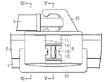
- FIG. 4 is a schematic partial enlarged view of the central portion of the screen device P1 during storage.
- the lock mechanism includes an engaging portion 9 attached to the upper surface of the top bar 5 and an engaged portion (not shown) that is disposed on the casing 1 side and engages with the engaging portion 9.
- the engagement portion 9 includes a support portion 14 and a pair of engagement members 11 and 12 which are disposed on the support portion 14 so as to be able to approach and separate from each other in the circumferential direction of the top bar 5.
- An operating portion locking mechanism 13 is provided between the engaging members to prevent the engaging members from approaching each other when engaged.
- FIG. 5 is a longitudinal sectional view taken along line VV in FIG.
- the casing 1 has a space 1a for unwinding the screen, and is composed of a case member extending in the longitudinal direction.
- the casing 1 has a curved structure in which the front surface on the projector side bulges toward the projector side, and the rear surface has an L-shaped cross section.
- the spring roll 2 around which the screen 4 is wound can be accommodated in the casing 1, and the width of the opening 1 a can be narrowed to reduce the size of the casing 1.
- an aluminum extrusion material can be used for the case member.
- a casing obtained by connecting a first case member and a second case member extending in the longitudinal direction can be used as the casing 1.
- one end in the width direction of the two case members is connected by a one-side hinge mechanism so as to be opened and closed, and the other end is separated from each other to form a space for unwinding the screen.
- a column attachment member 25 that pivotally supports the column 6 is attached to the rear surface of the casing 1.
- a protective member 26 that is in close contact with the casing 1 and extends to the bottom of the casing 1 is attached to the center of the front surface of the casing 1.
- one end of the protective member 26 is fastened to the bottom of the casing 1 by rivets 28 and 29, and the other end is fastened and fixed by a rivet 27.
- pillar attachment member 25 and the protection member 26 are mutually fitted and fixed.
- the protective member 26 has an effect of preventing the front portion of the casing from being further curved and deformed to the projector side due to the load of the top bar. It is preferable to use a highly elastic and lightweight resin cover for the protective member.
- the protective member 26 does not necessarily have to be attached to the entire front central portion, and can be attached to cover the upper half or at least the opening edge of the front central portion of the casing.
- the lock mechanism 8 includes an engaging portion 9 and an engaged portion 10. Further, the engaging portion 9 is composed of a pair of engaging portions of a first engaging portion 11 and a second engaging portion 12.
- the first engaging member 11a and the second engaging member 12a constituting the first engaging portion 11 and the second engaging portion 12, respectively, are arranged opposite to each other in the width direction of the top bar 5, and the longitudinal direction of the top bar. Is pivotally supported by the base 14 so as to be rotatable in a vertical part. Further, each of the engaging members 11a and 12a is operated to operate engagement / release of the engagement end portions 111a and 121a engaged with the engaged portion 10 at one end and the engagement end portions 111a and 121a at the other end, respectively. It has parts 112a and 122a.
- the top bar 5 shows an example in which an engagement claw is used for the engagement end portions 111a and 121a and a convex handle portion is used for the operation portions 112a and 122a.
- the top bar 5 includes a support bar 5a and a protective cover 5b.
- the engaged portion 10 is composed of a pair of engaged members 15 and 16.
- the engaged members 15 and 16 are disposed at the opening edge of the casing 1 and engage with the engaging claw.
- Each of the engaging portions of the first engaging portion 11 and the second engaging portion 12 has a first spring member 11b and a second spring having one end engaged with the base and the other end engaged with the engaging member.
- the member 12b is included. This spring member always urges the operating portions 112a and 122a at one end of the engaging member in a direction away from each other, and presses the engaging end at the other end in the top bar direction.
- FIG. 5 shows a case where the engaged members 15 and 16 are integrated with the column attachment member 25 and the protection member 26, respectively. However, the engaged members 15 and 16 are protected with the column attachment member 25, respectively. The member 26 may be separated. Moreover, the to-be-engaged member 15 attached to the front side of the casing can be attached so as to cover the opening edge of the casing, and the protective member can be omitted.
- the engagement end portions 111a and 121a are engaged with the engaged members 15 and 16, respectively, as shown in FIG.
- the operation portion 112a and the operation portion 122a are pressed toward each other against the biasing force of the spring member.
- the engaging members 11a and 12a rotate in a direction in which the engaging end portions 111a and 121a are separated from the engaged members 15 and 16, and the engagement between the engaging end portion and the engaged member is released.
- the engagement end portion with the engaged member when closing the opening of the casing with the top bar, the engagement portion is pressed downward, and the engaged member and the engagement end portion are Engage. Due to the urging force of the spring member, the engaging end is engaged in a state of being pressed against the engaged member.
- the operation unit lock mechanism is a mechanism that prevents malfunction of the lock mechanism. For example, when the stored screen device is moved, when the handle is gripped, the top bar may be pushed out of the casing by accidentally pressing the operation parts in a direction approaching each other. By providing the operation unit lock mechanism, when the lock mechanism is in the engaged state, it is possible to prevent the operation unit from moving and releasing the engaged state.
- the lock member 13 is fitted to the base portion 14 so as to be rotatable between a lock position and a release position, and is in the lock position shown in FIG. 5 when the lock mechanism is engaged. At this lock position, both ends of the head of the lock member 13 are brought into contact with the operation units 112a and 122a, respectively, to prevent the operation unit from approaching. On the other hand, in the release position, the lock member is rotated so as to release the contact between the both end portions and each operation portion, thereby allowing the operation portions to approach each other. Thereby, in the release position, the lock mechanism can be released, the top bar can be fixed to the casing, and the screen can be unwound.
- FIG. 6 is a longitudinal sectional view taken along line VI-VI in FIG. 4 and shows a configuration of the positioning mechanism 17 for accurately aligning the engaging portion and the engaged portion of the lock mechanism.
- the positioning mechanism 17 includes a guide portion 18 formed on the opening edge of the casing so as to be aligned with the engaged portion, and a guided portion formed on the base portion 14 of the lock mechanism and capable of loosely fitting with the guide portion 18.
- the guide part 18 is composed of a pair of projecting edge parts 20 and 21 arranged at the opening edge part facing the casing.
- Each protruding edge portion can be composed of at least one protruding portion, but it is preferable that two or more protruding portions are disposed on both sides of the engaged member.
- the guided portion 19 includes guide grooves 22 and 23 formed on the front surface side and the rear surface side of the base portion 14.
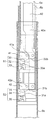
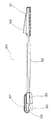
- FIG. 7 is a schematic cross-sectional view showing an example of an extendable strut used in the portable screen device of the present invention.
- the 1st cylinder and the 2nd cylinder are shortened, and the support
- the support columns are disposed at the lower ends of the first cylinder body 6a and the second cylinder body 6b, respectively, and a first lock section and a second lock that lock the sliding of the cylinder bodies by frictional force with the adjacent outer cylinder bodies Part.
- the first lock portion 51 includes a sliding member 30 having a tapered surface 30a inclined toward an inner wall of an adjacent outer cylindrical body (second cylindrical body) at least at a part of the circumferential surface, and the tapered surface 30a and the first It has a stopper 32 held between the two cylinders, and an elastic member 33 that urges the stopper 32 so as to abut against the tapered surface 30a.
- a part of the sliding member 30 is fixed to the lower end portion of the first cylindrical body 6a.
- a spring member can be used as the elastic member 33, one end of the spring member is engaged with the sliding member 30, and the other end is engaged with one end of the stopper 32.
- the second lock portion 52 includes a sliding member 31 having a tapered surface 31a inclined toward an inner wall of an adjacent outer cylindrical body (third cylindrical body) at least at a part of the circumferential surface, and the tapered surface 31a. And a third cylindrical body, and a resilient member 34 that urges the stopper to abut against the tapered surface 31a.
- a part of the sliding member 31 is fixed to the lower end portion of the second cylindrical body 6b.
- a spring member can be used as the elastic member 34, and one end of the spring member is engaged with the sliding member 31, and the other end is engaged with one end of the stopper 34.
- a release bar 40 having an upper end pivotally supported by a later-described lock release lever is arranged inside the first cylinder 6a so as to be movable up and down in the first cylinder.
- the lower end 40 a of the release bar 40 is provided with a first lock release portion 41 that releases the corresponding first lock portion 51 and a second lock release portion 42 that releases the corresponding second lock portion 52.
- the first unlocking portion 41 is composed of a swing member 41 whose one end is pivotally supported by the lower end portion 40 a of the release bar 40 and whose other end swings in conjunction with the lifting of the release bar 40.
- the second unlocking portion 42 includes a swinging member 42 having a lower end portion 40a of the releasing bar 40 spaced apart from the first unlocking portion 41 by a predetermined distance and having one end pivotally supported downward and the other end swinging. Has been.
- the first lock part 51 and the second lock part 52 are in an operating state (locked state), and the first cylinder body 6a and the second cylinder body 6b are fixed. That is, the stopper 32 of the first lock portion 51 is urged upward by the elastic member 33, abuts against the tapered surface 30a and the inner wall of the second cylinder 6b, generates a frictional force, and fixes the first cylinder 6a. To do.
- the stopper 34 of the second lock portion 52 is urged upward by the elastic member 33 and abuts against the tapered surface 31a and the inner wall of the third cylinder 6c to generate a frictional force, thereby fixing the second cylinder 6b. To do.
- the swinging member 41 has one end portion pivotally supported against the flat portion 30b of the sliding member 30, the swinging member 41 is in a horizontal state, and the other end portion does not press the stopper 32.
- the stopper is separated or in a simple contact state. The same applies to the swing member 42, and the other end portion does not press the stopper 34.
- the oscillating member 41 and the oscillating member 42 are provided with fulcrum shaft portions 41a and 42a at the substantially central portions of the side surfaces, respectively. It is supported by a bearing groove (not shown) provided on the inner surface.
- This fulcrum shaft portion operates as a fulcrum for lever operation when swinging, and can press the stopper more strongly.
- the shape of the stopper is not particularly limited as long as it can be held between the sliding member and the inner wall of the cylindrical body, but a stopper having an inclined surface capable of contacting the tapered surface of the sliding member is preferable.
- a stopper having an inclined surface capable of contacting the tapered surface of the sliding member is preferable.
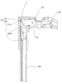
- FIG. 10 is a schematic cross-sectional view showing the structure of the hook portion 7 attached to the distal end portion of the first cylindrical body 6a.
- the hook portion 7 has a hook portion 72 for hooking the top bar on the surface thereof, and a lock release lever 71 is arranged inside the hook portion 7.
- One end and the other end of the lock release lever 71 are supported so as to be able to swing up and down with a shaft stopping portion 71a as a fulcrum.
- one end of the lock release lever 71 is disposed on the front side of the hook to constitute the operation portion 71b, and the other end is connected to the upper end portion 40b of the release bar 40 to constitute a connection portion 71c.
- the shaft stopper 71a is provided with a spring member (not shown) that urges the operation portion 71b upward.
- the release bar 40 having the lock release portion and the lock release lever 71 constitute the lock release mechanism 50.
- the support column When not in use, as shown in FIG. 3, the support column is tilted and stored so as to be substantially parallel to the casing.
- the top bar is fixed to the casing as a lid of the casing and is extremely easy to store and carry. Further, the hook portion at the tip of the support column is rotatably supported by the support column.
- the operation bar lock mechanism of the lock mechanism is released, and the operation parts are pressed in directions approaching each other, thereby releasing the fixing of the top bar against caging.
- the screen is unwound from the spring roll against the elastic force and gravity of the spring attached to the spring roll. Subsequently, the screen is held in a stretched state by hooking a handle disposed on the top bar to the hook portion of the column.
- the hook portion when the hook portion is pulled down while the operation portion of the lock release lever is pressed, the lock state of only the first lock portion is released, and the first cylinder can be pushed into the second cylinder. If the hook portion is further pulled down while the operation portion of the lock release lever is pressed, the locked state of the second lock portion is released and the second cylinder can be pushed into the third cylinder.
- the second lock unit is also locked as shown in FIG. With the support column at the shortest length, the support column is tilted and stored in parallel with the casing.
- a plurality of lock portions that lock the slides between the cylinders by the frictional force with the adjacent outer cylinders are provided, and a plurality of corresponding parts are provided. Since the unlocking portion is arranged to be movable up and down in the cylinder, the height of the support column can be adjusted to an arbitrary height steplessly.
- the strut can be extended from the shortest state to the longest state or use height at once, or conversely, the longest state or use height to the shortest state. Since it can be shortened at a time, it is very easy to extend and shorten the column.
- the operation part of the unlocking lever is provided on the front side of the hook part, the height of the support can be adjusted on the front side of the screen.
- an example in which a support column composed of a three-stage cylindrical body is used is not particularly limited as long as the number of stages is two or more.
- a third lock is provided at the lower end of the third cylinder, and a third lock release is provided at the lower end of the release bar corresponding to the third lock.
- a lock part is provided at the lower end of all the cylinders preceding the lowest cylinder, and a lock release part corresponding to the lock part is provided on the release bar. Just do it.
- the first lock portion includes a first locking portion including a plurality of through holes provided in the longitudinal direction of the second cylinder, and the first tube.
- a first engaging portion that is provided at a lower end portion of the body and engageable with the first locking portion, and the second locking portion is formed of a plurality of through holes provided in a longitudinal direction of the third cylindrical body.
- a second engagement portion that is provided at the lower end portion of the second cylinder and can be engaged with the second engagement portion, and the first engagement portion is provided at the lower end portion of the release bar.
- the mechanism for unlocking is not particularly limited as long as it is a mechanism capable of releasing the engagement with the through hole.
- a convex member that is constantly urged by an elastic member so as to be engaged with a locking portion formed of a through hole is used as the engaging portion, and the engaging portion is pressed so that the engagement is released.
- a mechanism can be used.
- a mechanism for releasing the engagement by providing an engaging portion that engages with the locking portion at one end of the lock releasing portion and swinging the lock releasing portion can also be used.
- the screen has been increased in size, and in the present invention, it is also possible to use a large screen of 100 inches or the like by increasing the height of the column. In that case, it is preferable to use an operation tool that can operate the lock release lever from a position away from it.
- 11 and 12 are a top view and a perspective view showing an example of the operation tool.
- the operating tool 80 is provided with a handle portion 81 at one end of a hollow shaft portion 82 and a release portion 83 that presses and releases a lock release lever at the other end.
- the release portion 83 is located on the axis of the shaft portion 83 and is in contact with the object to be released, and a pair of fixed protrusions 85 that are provided on both sides of the movable protrusion 87 and hold the movable protrusion 8. , 86.
- the movable protrusion 87 is connected to the operation portion 84 provided on the handle portion 81 via a connecting member (not shown) inserted into the shaft portion 83. When the operation portion 84 is pushed in, the movable protrusion 87 is connected. Can be slid to the handle side on the axis of the shaft portion 83.
- the operating tool can be used as follows, for example.
- the top bar is hooked on the hook portion, and the release portion of the operation tool is pressed against the front surface of the hook portion so that the movable protrusion comes into contact with the lock release lever.
- the fixed projection acts as a holding portion for bringing the movable projection into contact with the unlock lever, and the lock is released as a result of the movable projection being pressed against the unlock lever by pushing the operating portion. be able to.
- the support By pushing up the hook portion in this state, the support can be extended.
- the support can be shortened by lowering the hook portion.
- the operation tool of the present invention it is possible to easily extend and store the screen by a simple operation even in a large screen device.
- the present invention it is possible to provide a portable screen device that can easily extend and contract the struts and is lightweight and easy to carry.
- the telescopic support column of the present invention is used as a support column of a portable screen device.
- the height (or length) of the support column can be easily set to a desired height (or length). Therefore, it can be widely used for telescopic struts that require simple operation.
Landscapes
- Physics & Mathematics (AREA)
- General Physics & Mathematics (AREA)
- Overhead Projectors And Projection Screens (AREA)
Abstract
Description
実施の形態1.
図1は、本実施の形態に係る可搬式スクリーン装置の使用時の状態の一例を示している。可搬式スクリーン装置P1は、ケーシング1と、ケーシング内に取付けられたスプリングロール(不図示)と、開口部1aから巻き出されトップバー5とスプリングロールとの間に展張されたスクリーン4と、ケーシング1の概ね中央に立設されスクリーン4を所定高さに保持する支柱6と、を備えている。支柱6は、ケーシング1の概ね中央に取着された支柱取り付け部材25により支持されたスライド伸縮可能な3段の筒体、すなわち、上段側から第1筒体6a、第2筒体6b、そして第3筒体6cで構成されている。また、支柱6はその先端に水平回動可能なフック部7を有しており、トップバー5の概ね中央に配設された、掛止部材を兼ねる持運び用のハンドル24をフック部7に掛止してスクリーン4を吊下げている。また、9はトップバー5をケーシング1に固定するロック機構を構成する係合部であり、収納時、ケーシング1に配設された被係合部(不図示)と係合する。また、スクリーン装置P1は、ケーシング1の底部から引出された一対の脚部3,3により直立するように支持されている。
支柱は、第1筒体6aと第2筒体6bの下端部にそれぞれ配設され、隣接する外側の筒体との摩擦力により筒体相互のスライドをロックする第1ロック部と第2ロック部とを有している。第1ロック部51は、隣接する外側の筒体(第2筒体)の内壁に向かって傾斜するテーパ面30aを少なくとも周面の一部に有する摺動部材30と、そのテーパ面30aと第2筒体との間に保持されるストッパ32と、そのストッパ32がテーパ面30aに当接するように付勢する弾性部材33とを有している。ここで、摺動部材30の一部は、第1筒体6aの下端部に固定されている。
弾性部材33としてはバネ部材を用いることができ、そのバネ部材の一端は摺動部材30に係着され、他端はストッパ32の一端に係着されている。
下端部40aには対応する第1ロック部51を解除する第1ロック解除部41と、対応する第2ロック部52を解除する第2ロック解除部42とが配設されている。
第1ロック解除部41は、解除バー40の下端部40aに一端が軸支され解除バー40の上昇に連動して他端が揺動する揺動部材41から構成されている。また、第2ロック解除部42は、解除バー40の下端部40aに第1ロック解除部41から所定距離離間して下方に一端が軸支され、他端が揺動する揺動部材42から構成されている。
非使用時においては、図3に示すように、支柱は倒されてケーシングに概ね平行になるように収納されている。トップバーはケーシングの蓋体としてケーシングに固定されており、収納及び持運びが極めて容易である。また、支柱の先端のフック部は回動可能に支柱に支持されている。
すなわち、本発明の別の態様に係る可搬式スクリーン装置は、上記第1ロック部は、第2筒体の長手方向に設けられた複数の貫通孔からなる第1係止部と、第1筒体の下端部に設けられ第1係止部と係合可能な第1係合部とを有し、上記第2ロック部は、第3筒体の長手方向に設けられた複数の貫通孔からなる第2係止部と、第2筒体の下端部に設けられ第2係止部と係合可能な第2係合部とを有し、解除バーの下端部に、第1係止部と第1係合部との係合を解除する第1ロック解除部と、その第1ロック解除部の下に第2係止部と第2係合部との係合を解除する第2ロック解除部とを設けるようにしたスクリーン展張用支柱を用いることができる。ロック解除の機構は、貫通孔との係合を解除できる機構であれば特に限定されない。例えば、係合部には、貫通孔からなる係止部と係合するように弾性部材により常時付勢された凸状部材を用い、その係合が解除するようにその係合部を押圧する機構を用いることができる。また、ロック解除部の一端に係止部と係合する係合部を設け、ロック解除部を揺動させることにより、その係合を解除する機構を用いることもできる。
Claims (18)
- 長手方向に延在する開口部を有するケーシングと、該ケーシングに回動自在に取り付けられたスプリングロールと、収納時には上記スプリングロールに巻回され、使用時には上記開口部から巻き出されるスクリーンと、該スクリーンの一端が固着され、収納時には上記開口部を塞ぐ蓋体を兼ねるトップバーと、該ケーシングに一端が支持され、巻き出したスクリーンを展張状態に保持する伸縮可能な支柱と、を有し、
上記支柱に、
少なくとも第1筒体と第2筒体と第3筒体を有し、前記第1筒体は前記第2筒体内を摺動し、前記第2筒体は第3筒体を摺動して、伸長時には上段から第1筒体、第2筒体、第3筒体の順に位置する伸縮支柱であって、
第1筒体のスライドをロックする第1ロック部と、
第2筒体のスライドをロックする第2ロック部と、
第1筒体の上端部に設けられたロック解除レバーと、第1筒体内を上下移動可能に上端部がロック解除レバーに軸支された解除バーと、
前記解除バーの下端部に設けられ、第1ロック部を解除する第1ロック解除部と、
前記解除バーの下端部に、前記第1ロック解除部より下に設けられ、第2ロック部を解除する第2ロック解除部と、を有する伸縮支柱を用いる可搬式スクリーン装置。 - 上記第1ロック部は、第1筒体の下端部に配設されてなり、第2筒体の内壁を押圧してその内壁との摩擦力により第1筒体のスライドをロックし、
上記第2ロック部は、第2筒体の下端部に配設されてなり、第3筒体の内壁を押圧してその内壁との摩擦力により第2筒体のスライドをロックし、
上記第1ロック解除部は、第1ロック部の第2筒体の内壁への押圧を解除することにより第1ロック部を解除し、
上記第2ロック解除部は、第2ロック部の第3筒体の内壁への押圧を解除することにより第2ロック部を解除する、請求項1記載の可搬式スクリーン装置。 - 上記第1ロック部は、第1筒体の下端部に一部が固定され、隣接する外側の筒体の内壁に向かって傾斜するテーパ面を少なくとも周面の一部に有する摺動部材と、
該テーパ面と該各筒体の下段の筒体との間に保持されるストッパと、
該ストッパが上記テーパ面に当接するように付勢する弾性部材とを有し、
上記第2ロック部は、第2筒体の下端部に一部が固定され、隣接する外側の筒体の内壁に向かって傾斜するテーパ面を少なくとも周面の一部に有する摺動部材と、
該テーパ面と該各筒体の下段の筒体との間に保持されるストッパと、
該ストッパが上記テーパ面に当接するように付勢する弾性部材とを有する請求項2記載の可搬式スクリーン装置。 - 上記ストッパが上記テーパ面に当接する傾斜面を有する請求項3記載の可搬式スクリーン装置。
- 上記第1ロック部は、第2筒体の長手方向に設けられた複数の貫通孔からなる第1係止部と、第1筒体の下端部に設けられ第1係止部と係合可能な第1係合部とを有し、
上記第2ロック部は、第3筒体の長手方向に設けられた複数の貫通孔からなる第2係止部と、第2筒体の下端部に設けられ第2係止部と係合可能な第2係合部とを有し、
解除バーの下端部に、第1係止部と第1係合部との係合を解除する第1ロック解除部と、その第1ロック解除部の下に第2係止部と第2係合部との係合を解除する第2ロック解除部とを設けるようにした請求項1記載の可搬式スクリーン装置。 - 上記トップバーの中央部にハンドル部を設ける一方、上記支柱の先端部にフック部を設け、該フック部に上記ハンドル部を掛止するようにした請求項1から5のいずれか一つに記載の可搬式スクリーン装置。
- 上記フック部には、上記解除バーに連結されかつ操作部がフック部の前面側に位置するように上記ロック解除レバーが配設されており、ロック解除レバーの操作部への押圧動作に連動して解除バーを上昇させる請求項6記載の可搬式スクリーン装置。
- 上記支柱は、該ケーシングの側面中央部に一端が起伏可能に軸支されており、起立時には巻き出したスクリーンを展張状態に保持する請求項1記載の可搬式スクリーン装置。
- 収納時に上記トップバーを上記ケーシングに固定するロック機構を有する請求項1記載の可搬式スクリーン装置。
- 上記ロック機構が、上記トップバー上に配設された係合部と、上記ケーシングに配設され該係合部と係合する被係合部を有する請求項9記載の可搬式スクリーン装置。
- 上記係合部が上記トップバーの幅方向に対向配設された一対の係合部材を有する一方、上記被係合部が上記ケーシングの対向する開口縁部にそれぞれ配設され上記係合部材と係合する一対の被係合部材を有する請求項10記載の可搬式スクリーン装置。
- 少なくとも第1筒体と第2筒体と第3筒体を有し、前記第1筒体は前記第2筒体内を摺動し、前記第2筒体は第3筒体を摺動して、伸長時には上段から第1筒体、第2筒体、第3筒体の順に位置する伸縮支柱であって、
第1筒体のスライドをロックする第1ロック部と、
第2筒体のスライドをロックする第2ロック部と、
第1筒体の上端部に設けられたロック解除レバーと、第1筒体内を上下移動可能に上端部がロック解除レバーに軸支された解除バーと、
前記解除バーの下端部に設けられ、第1ロック部を解除する第1ロック解除部と、
前記解除バーの下端部に、前記第1ロック解除部より下に設けられ、第2ロック部を解除する第2ロック解除部と、を有する伸縮支柱。 - 上記第1ロック部は、第1筒体の下端部に配設されてなり、第2筒体の内壁を押圧してその内壁との摩擦力により第1筒体のスライドをロックし、
上記第2ロック部は、第2筒体の下端部に配設されてなり、第3筒体の内壁を押圧してその内壁との摩擦力により第2筒体のスライドをロックし、
上記第1ロック解除部は、第1ロック部の第2筒体の内壁への押圧を解除することにより第1ロック部を解除し、
上記第2ロック解除部は、第2ロック部の第3筒体の内壁への押圧を解除することにより第2ロック部を解除する、請求項12記載の伸縮支柱。 - 上記第1ロック部は、第1筒体の下端部に一部が固定され、隣接する外側の筒体の内壁に向かって傾斜するテーパ面を少なくとも周面の一部に有する摺動部材と、
該テーパ面と該各筒体の下段の筒体との間に保持されるストッパと、
該ストッパが上記テーパ面に当接するように付勢する弾性部材とを有し、
上記第2ロック部は、第2筒体の下端部に一部が固定され、隣接する外側の筒体の内壁に向かって傾斜するテーパ面を少なくとも周面の一部に有する摺動部材と、
該テーパ面と該各筒体の下段の筒体との間に保持されるストッパと、
該ストッパが上記テーパ面に当接するように付勢する弾性部材とを有する請求項13記載の伸縮支柱。 - 上記ストッパが上記テーパ面に当接する傾斜面を有する請求項12から14のいずれか一つに記載の伸縮支柱。
- 上記第1ロック部は、第2筒体の長手方向に設けられた複数の貫通孔からなる第1係止部と、第1筒体の下端部に設けられ第1係止部と係合可能な第1係合部とを有し、
上記第2ロック部は、第3筒体の長手方向に設けられた複数の貫通孔からなる第2係止部と、第2筒体の下端部に設けられ第2係止部と係合可能な第2係合部とを有し、
解除バーの下端部に、第1係止部と第1係合部との係合を解除する第1ロック解除部と、その第1ロック解除部の下に第2係止部と第2係合部との係合を解除する第2ロック解除部とを設けるようにした請求項15記載の伸縮支柱。 - 4本以上の筒体からなる支柱であって、第3筒体より下段の筒体において、前段の筒体の下端部にロック部を設ける一方、上記解除バーにそのロック部に対応するロック解除部を設けてなる請求項12記載の伸縮支柱。
- 請求項1から11のいずれか一つに記載の可搬式スクリーン装置に用いる操作具であって、軸部の一端に把手部を設け、他端にはロック解除レバーを押圧して解除する解除部を設け、該解除部は、該軸部の軸線上に位置し被解除物に当接する可動突部と、該可動突部の両側に設けられ、該可動突部を保持する一対の固定突部とを有する操作具。
Priority Applications (4)
| Application Number | Priority Date | Filing Date | Title |
|---|---|---|---|
| CN2009801155651A CN102016715B (zh) | 2008-05-02 | 2009-04-24 | 移动式投影屏装置及其所用伸缩支柱和操作工具 |
| US12/936,802 US8159745B2 (en) | 2008-05-02 | 2009-04-24 | Portable screen assembly and expanding and contracting column and handing tool used therefor |
| JP2010510092A JPWO2009133808A1 (ja) | 2008-05-02 | 2009-04-24 | 可搬式スクリーン装置及びそれに用いる伸縮支柱並びに操作具 |
| EP09738745A EP2273312A4 (en) | 2008-05-02 | 2009-04-24 | PORTABLE SCREEN DEVICE AND REMOVABLE SUPPORT AND OPERATING DEVICE THEREFOR |
Applications Claiming Priority (4)
| Application Number | Priority Date | Filing Date | Title |
|---|---|---|---|
| JP2008-120217 | 2008-05-02 | ||
| JP2008120217 | 2008-05-02 | ||
| CN200920000370.X | 2009-02-09 | ||
| CN200920000370XU CN201434963Y (zh) | 2008-05-02 | 2009-02-09 | 移动式投影屏装置及其所用伸缩支柱和操作工具 |
Publications (1)
| Publication Number | Publication Date |
|---|---|
| WO2009133808A1 true WO2009133808A1 (ja) | 2009-11-05 |
Family
ID=42053776
Family Applications (1)
| Application Number | Title | Priority Date | Filing Date |
|---|---|---|---|
| PCT/JP2009/058123 Ceased WO2009133808A1 (ja) | 2008-05-02 | 2009-04-24 | 可搬式スクリーン装置及びそれに用いる伸縮支柱並びに操作具 |
Country Status (6)
| Country | Link |
|---|---|
| US (1) | US8159745B2 (ja) |
| EP (1) | EP2273312A4 (ja) |
| JP (1) | JPWO2009133808A1 (ja) |
| KR (1) | KR20110016908A (ja) |
| CN (2) | CN201434963Y (ja) |
| WO (1) | WO2009133808A1 (ja) |
Cited By (2)
| Publication number | Priority date | Publication date | Assignee | Title |
|---|---|---|---|---|
| NL1037668C2 (nl) * | 2010-02-01 | 2011-08-03 | Smit Visual Supplies B V | Mobiele presentatie-inrichting. |
| WO2017119420A1 (ja) * | 2016-01-08 | 2017-07-13 | 泉株式会社 | 可搬式スクリーン装置 |
Families Citing this family (13)
| Publication number | Priority date | Publication date | Assignee | Title |
|---|---|---|---|---|
| CN201434963Y (zh) * | 2008-05-02 | 2010-03-31 | 泉株式会社 | 移动式投影屏装置及其所用伸缩支柱和操作工具 |
| WO2011094846A1 (en) * | 2010-02-03 | 2011-08-11 | Visual Sports Systems | Collapsible enclosure for playing games on computers and gaming consoles |
| US9036256B2 (en) * | 2010-09-18 | 2015-05-19 | Christian Hopf | Display unit having a projection screen for a head-up display |
| CN202472230U (zh) * | 2012-03-07 | 2012-10-03 | 极品影视设备科技(深圳)有限公司 | 隐藏式投影幕 |
| CA160318S (en) * | 2014-07-10 | 2016-07-07 | Kg Spennare Ab | Display unit |
| US9877002B2 (en) * | 2015-10-02 | 2018-01-23 | Samsung Electronics Co., Ltd. | Reconfigurable mobile device |
| AU367003S (en) * | 2015-10-06 | 2016-02-10 | Botak Sign Pte Ltd | Display stand |
| CN106707677A (zh) * | 2017-02-26 | 2017-05-24 | 余治蓉 | 一种自动投影幕 |
| US11565816B2 (en) | 2020-08-17 | 2023-01-31 | Windham Packaging, Llc | Portable airline inter-passenger shield |
| USD978226S1 (en) * | 2020-11-10 | 2023-02-14 | Emart International Inc | Collapsible screen |
| USD939616S1 (en) * | 2020-11-29 | 2021-12-28 | Wuxi Donghui Video Equipment Co. Ltd. | Projection screen |
| USD942528S1 (en) * | 2021-01-08 | 2022-02-01 | Caipeng Zou | Backdrop holder |
| USD972623S1 (en) * | 2021-05-24 | 2022-12-13 | ShenZhen Screen Workshop Technology Ltd. | Electric motorized floor screen |
Citations (3)
| Publication number | Priority date | Publication date | Assignee | Title |
|---|---|---|---|---|
| JPH0636048U (ja) | 1992-10-02 | 1994-05-13 | 株式会社オーエス | 卓上型映写スクリーン |
| WO2005043235A1 (ja) * | 2003-10-31 | 2005-05-12 | Izumi-Cosmo Company Limited | 可搬式スクリーン装置 |
| JP2006072291A (ja) * | 2004-08-02 | 2006-03-16 | Izumi-Cosmo Co Ltd | 可搬式スクリーン装置 |
Family Cites Families (19)
| Publication number | Priority date | Publication date | Assignee | Title |
|---|---|---|---|---|
| US2845244A (en) * | 1954-07-30 | 1958-07-29 | Da Lite Screen Inc | Tripod |
| US3182714A (en) * | 1963-04-24 | 1965-05-11 | Knox Mfg Company | Tensioner mechanism for a portable movie screen |
| US3225818A (en) * | 1963-08-14 | 1965-12-28 | Glenn E Wise | Projection screen |
| US3314467A (en) * | 1964-06-04 | 1967-04-18 | Radiant Mfg Corp | Collapsible portable projection screen |
| US3324928A (en) * | 1964-06-29 | 1967-06-13 | Agfa Ag | Collapsible portable projection screen |
| US3245644A (en) * | 1964-10-05 | 1966-04-12 | Radiant Mfg Corp | Portable projection screen assembly |
| US3629910A (en) * | 1969-11-28 | 1971-12-28 | Graflex Inc | Handle assembly for picture projection screen |
| US5267480A (en) * | 1992-07-10 | 1993-12-07 | Douglas Autotech Corporation | Telescoping column |
| JPH0636048A (ja) | 1992-07-13 | 1994-02-10 | Toshiba Corp | ボリュームデータクリッピング方式 |
| FR2745607B1 (fr) * | 1996-03-01 | 1998-05-15 | Deville Sa | Dispositif d'assemblage eet de verrouillage de deux tubes, et son application pour la realisation d'une perche telescopique |
| US6343404B1 (en) * | 2000-06-21 | 2002-02-05 | Chaw Khong Technology Co., Ltd. | Multi-step positioning device of trunk pull rod |
| US20040079845A1 (en) * | 2002-10-22 | 2004-04-29 | Wilcox James F. | Internal telescopic tube locking device |
| US6991019B2 (en) * | 2003-08-06 | 2006-01-31 | Wei Chi Chang | Screen |
| CN2816856Y (zh) * | 2005-06-03 | 2006-09-13 | 伍炳康 | 便携式地拉幕 |
| US7426077B2 (en) * | 2006-10-24 | 2008-09-16 | Izumi-Cosmo Company, Limited | Portable screen device |
| CN201021970Y (zh) * | 2007-02-13 | 2008-02-13 | 广州美视晶莹银幕有限公司 | 轻便可移动式座地升降投影幕 |
| CN201434963Y (zh) * | 2008-05-02 | 2010-03-31 | 泉株式会社 | 移动式投影屏装置及其所用伸缩支柱和操作工具 |
| CN201434962Y (zh) * | 2008-05-02 | 2010-03-31 | 泉株式会社 | 移动式投影屏装置 |
| US8303594B2 (en) * | 2008-12-30 | 2012-11-06 | Howmedica Osteonics Corp. | Method and apparatus for removal of tissue |
-
2009
- 2009-02-09 CN CN200920000370XU patent/CN201434963Y/zh not_active Expired - Lifetime
- 2009-04-24 JP JP2010510092A patent/JPWO2009133808A1/ja active Pending
- 2009-04-24 KR KR1020107027135A patent/KR20110016908A/ko not_active Withdrawn
- 2009-04-24 WO PCT/JP2009/058123 patent/WO2009133808A1/ja not_active Ceased
- 2009-04-24 US US12/936,802 patent/US8159745B2/en not_active Expired - Fee Related
- 2009-04-24 EP EP09738745A patent/EP2273312A4/en not_active Withdrawn
- 2009-04-24 CN CN2009801155651A patent/CN102016715B/zh not_active Expired - Fee Related
Patent Citations (3)
| Publication number | Priority date | Publication date | Assignee | Title |
|---|---|---|---|---|
| JPH0636048U (ja) | 1992-10-02 | 1994-05-13 | 株式会社オーエス | 卓上型映写スクリーン |
| WO2005043235A1 (ja) * | 2003-10-31 | 2005-05-12 | Izumi-Cosmo Company Limited | 可搬式スクリーン装置 |
| JP2006072291A (ja) * | 2004-08-02 | 2006-03-16 | Izumi-Cosmo Co Ltd | 可搬式スクリーン装置 |
Non-Patent Citations (1)
| Title |
|---|
| See also references of EP2273312A4 * |
Cited By (3)
| Publication number | Priority date | Publication date | Assignee | Title |
|---|---|---|---|---|
| NL1037668C2 (nl) * | 2010-02-01 | 2011-08-03 | Smit Visual Supplies B V | Mobiele presentatie-inrichting. |
| WO2017119420A1 (ja) * | 2016-01-08 | 2017-07-13 | 泉株式会社 | 可搬式スクリーン装置 |
| US10379434B2 (en) | 2016-01-08 | 2019-08-13 | Izumi-Cosmo Company, Limited | Portable screen device |
Also Published As
| Publication number | Publication date |
|---|---|
| CN102016715B (zh) | 2012-10-10 |
| US8159745B2 (en) | 2012-04-17 |
| EP2273312A4 (en) | 2011-05-11 |
| CN102016715A (zh) | 2011-04-13 |
| EP2273312A1 (en) | 2011-01-12 |
| KR20110016908A (ko) | 2011-02-18 |
| JPWO2009133808A1 (ja) | 2011-09-01 |
| CN201434963Y (zh) | 2010-03-31 |
| US20110032612A1 (en) | 2011-02-10 |
Similar Documents
| Publication | Publication Date | Title |
|---|---|---|
| JPWO2009133808A1 (ja) | 可搬式スクリーン装置及びそれに用いる伸縮支柱並びに操作具 | |
| CN102016716B (zh) | 移动式投影屏装置 | |
| US7636194B2 (en) | Portable screen assembly | |
| KR100787521B1 (ko) | 자립식 수동 승강 스크린 | |
| JP3155340U (ja) | 移動式ディスプレイ取付装置 | |
| US20120162760A1 (en) | Portable Projection Screen | |
| KR101403149B1 (ko) | 접이식 삼각대 | |
| JP3166219U (ja) | 携帯式投影幕 | |
| JP5445182B2 (ja) | 投射光学装置の支持装置及びこれを備えた投射光学装置 | |
| US2659559A (en) | Picture screen stand | |
| CN101799107A (zh) | 便携三脚架 | |
| US7426077B2 (en) | Portable screen device | |
| JP2010128424A (ja) | スクリーン | |
| JP4068133B2 (ja) | 可搬式スクリーン装置 | |
| JP2008122997A (ja) | 可搬式スクリーン装置 | |
| JP4428426B2 (ja) | スクリーン | |
| CN205118595U (zh) | 显示屏伸缩架 | |
| JP4157908B2 (ja) | 可搬式スクリーン装置 | |
| JP2006072291A (ja) | 可搬式スクリーン装置 | |
| CN118058578A (zh) | 一种便携式拆装桌体 | |
| JP2007334160A (ja) | スライドアップスクリーン装置 |
Legal Events
| Date | Code | Title | Description |
|---|---|---|---|
| WWE | Wipo information: entry into national phase |
Ref document number: 200980115565.1 Country of ref document: CN |
|
| 121 | Ep: the epo has been informed by wipo that ep was designated in this application |
Ref document number: 09738745 Country of ref document: EP Kind code of ref document: A1 |
|
| WWE | Wipo information: entry into national phase |
Ref document number: 2010510092 Country of ref document: JP |
|
| WWE | Wipo information: entry into national phase |
Ref document number: 12936802 Country of ref document: US |
|
| WWE | Wipo information: entry into national phase |
Ref document number: 2009738745 Country of ref document: EP |
|
| NENP | Non-entry into the national phase |
Ref country code: DE |
|
| ENP | Entry into the national phase |
Ref document number: 20107027135 Country of ref document: KR Kind code of ref document: A |