WO2009136559A1 - 車両周辺表示装置 - Google Patents
車両周辺表示装置 Download PDFInfo
- Publication number
- WO2009136559A1 WO2009136559A1 PCT/JP2009/058193 JP2009058193W WO2009136559A1 WO 2009136559 A1 WO2009136559 A1 WO 2009136559A1 JP 2009058193 W JP2009058193 W JP 2009058193W WO 2009136559 A1 WO2009136559 A1 WO 2009136559A1
- Authority
- WO
- WIPO (PCT)
- Prior art keywords
- line
- vehicle
- index
- display device
- shadow
- Prior art date
- Legal status (The legal status is an assumption and is not a legal conclusion. Google has not performed a legal analysis and makes no representation as to the accuracy of the status listed.)
- Ceased
Links
Images








Classifications
-
- B—PERFORMING OPERATIONS; TRANSPORTING
- B60—VEHICLES IN GENERAL
- B60R—VEHICLES, VEHICLE FITTINGS, OR VEHICLE PARTS, NOT OTHERWISE PROVIDED FOR
- B60R1/00—Optical viewing arrangements; Real-time viewing arrangements for drivers or passengers using optical image capturing systems, e.g. cameras or video systems specially adapted for use in or on vehicles
- B60R1/20—Real-time viewing arrangements for drivers or passengers using optical image capturing systems, e.g. cameras or video systems specially adapted for use in or on vehicles
- B60R1/22—Real-time viewing arrangements for drivers or passengers using optical image capturing systems, e.g. cameras or video systems specially adapted for use in or on vehicles for viewing an area outside the vehicle, e.g. the exterior of the vehicle
- B60R1/23—Real-time viewing arrangements for drivers or passengers using optical image capturing systems, e.g. cameras or video systems specially adapted for use in or on vehicles for viewing an area outside the vehicle, e.g. the exterior of the vehicle with a predetermined field of view
- B60R1/26—Real-time viewing arrangements for drivers or passengers using optical image capturing systems, e.g. cameras or video systems specially adapted for use in or on vehicles for viewing an area outside the vehicle, e.g. the exterior of the vehicle with a predetermined field of view to the rear of the vehicle
-
- B—PERFORMING OPERATIONS; TRANSPORTING
- B62—LAND VEHICLES FOR TRAVELLING OTHERWISE THAN ON RAILS
- B62D—MOTOR VEHICLES; TRAILERS
- B62D15/00—Steering not otherwise provided for
- B62D15/02—Steering position indicators ; Steering position determination; Steering aids
- B62D15/027—Parking aids, e.g. instruction means
- B62D15/0275—Parking aids, e.g. instruction means by overlaying a vehicle path based on present steering angle over an image without processing that image
-
- B—PERFORMING OPERATIONS; TRANSPORTING
- B60—VEHICLES IN GENERAL
- B60R—VEHICLES, VEHICLE FITTINGS, OR VEHICLE PARTS, NOT OTHERWISE PROVIDED FOR
- B60R2300/00—Details of viewing arrangements using cameras and displays, specially adapted for use in a vehicle
- B60R2300/10—Details of viewing arrangements using cameras and displays, specially adapted for use in a vehicle characterised by the type of camera system used
- B60R2300/105—Details of viewing arrangements using cameras and displays, specially adapted for use in a vehicle characterised by the type of camera system used using multiple cameras
-
- B—PERFORMING OPERATIONS; TRANSPORTING
- B60—VEHICLES IN GENERAL
- B60R—VEHICLES, VEHICLE FITTINGS, OR VEHICLE PARTS, NOT OTHERWISE PROVIDED FOR
- B60R2300/00—Details of viewing arrangements using cameras and displays, specially adapted for use in a vehicle
- B60R2300/30—Details of viewing arrangements using cameras and displays, specially adapted for use in a vehicle characterised by the type of image processing
- B60R2300/304—Details of viewing arrangements using cameras and displays, specially adapted for use in a vehicle characterised by the type of image processing using merged images, e.g. merging camera image with stored images
- B60R2300/305—Details of viewing arrangements using cameras and displays, specially adapted for use in a vehicle characterised by the type of image processing using merged images, e.g. merging camera image with stored images merging camera image with lines or icons
-
- B—PERFORMING OPERATIONS; TRANSPORTING
- B60—VEHICLES IN GENERAL
- B60R—VEHICLES, VEHICLE FITTINGS, OR VEHICLE PARTS, NOT OTHERWISE PROVIDED FOR
- B60R2300/00—Details of viewing arrangements using cameras and displays, specially adapted for use in a vehicle
- B60R2300/30—Details of viewing arrangements using cameras and displays, specially adapted for use in a vehicle characterised by the type of image processing
- B60R2300/307—Details of viewing arrangements using cameras and displays, specially adapted for use in a vehicle characterised by the type of image processing virtually distinguishing relevant parts of a scene from the background of the scene
-
- B—PERFORMING OPERATIONS; TRANSPORTING
- B60—VEHICLES IN GENERAL
- B60R—VEHICLES, VEHICLE FITTINGS, OR VEHICLE PARTS, NOT OTHERWISE PROVIDED FOR
- B60R2300/00—Details of viewing arrangements using cameras and displays, specially adapted for use in a vehicle
- B60R2300/80—Details of viewing arrangements using cameras and displays, specially adapted for use in a vehicle characterised by the intended use of the viewing arrangement
- B60R2300/806—Details of viewing arrangements using cameras and displays, specially adapted for use in a vehicle characterised by the intended use of the viewing arrangement for aiding parking
-
- G—PHYSICS
- G08—SIGNALLING
- G08B—SIGNALLING SYSTEMS, e.g. PERSONAL CALLING SYSTEMS; ORDER TELEGRAPHS; ALARM SYSTEMS
- G08B13/00—Burglar, theft or intruder alarms
- G08B13/18—Actuation by interference with heat, light, or radiation of shorter wavelength; Actuation by intruding sources of heat, light, or radiation of shorter wavelength
- G08B13/189—Actuation by interference with heat, light, or radiation of shorter wavelength; Actuation by intruding sources of heat, light, or radiation of shorter wavelength using passive radiation detection systems
- G08B13/194—Actuation by interference with heat, light, or radiation of shorter wavelength; Actuation by intruding sources of heat, light, or radiation of shorter wavelength using passive radiation detection systems using image scanning and comparing systems
- G08B13/196—Actuation by interference with heat, light, or radiation of shorter wavelength; Actuation by intruding sources of heat, light, or radiation of shorter wavelength using passive radiation detection systems using image scanning and comparing systems using television cameras
- G08B13/19617—Surveillance camera constructional details
- G08B13/19619—Details of casing
-
- H—ELECTRICITY
- H04—ELECTRIC COMMUNICATION TECHNIQUE
- H04N—PICTORIAL COMMUNICATION, e.g. TELEVISION
- H04N7/00—Television systems
- H04N7/18—Closed-circuit television [CCTV] systems, i.e. systems in which the video signal is not broadcast
- H04N7/181—Closed-circuit television [CCTV] systems, i.e. systems in which the video signal is not broadcast for receiving images from a plurality of remote sources
Definitions
- the present invention relates to a vehicle periphery display device including an image acquisition unit that acquires a vehicle periphery image captured by an image capturing device provided in the vehicle, and a display device that is provided in a vehicle interior and displays the periphery image.
- Patent Document 1 discloses a technique for superimposing and displaying an index line indicating a predicted travel path to a parking target position based on a steering angle of a steering operation by a driver when the vehicle is parked. .
- the index lines are displayed in a plane on the periphery image of the vehicle having a three-dimensional depth.
- the index line should lie with respect to the road plane reflected in the peripheral image, but it is difficult to recognize the positional relationship between the peripheral image and the index line.
- it is difficult to intuitively recognize the index line for example, it is difficult to distinguish between the line drawn on the road and the index line.
- the present invention has been made in view of the above problems, and an object thereof is to provide a peripheral display device that can easily recognize an index line.
- a first characteristic configuration of the present invention is an image acquisition unit that acquires a surrounding image of a vehicle photographed by a photographing device provided in the vehicle, a display device that is provided in a vehicle interior and displays the surrounding image, and a driver An index line output unit for displaying an index line serving as an index of the driver in a superimposed manner on the peripheral image with at least one of a shadow part and a side part adjacent to the index line at the time of driving operation It is in the point.
- the shadow portion when the shadow portion is provided, it is possible to generate a visual effect such that the index line is lifted with respect to the surrounding image of the vehicle having a three-dimensional depth by the shadow portion. That is, it is possible to produce a visual effect as if the occupant sees the index line actually arranged on the road surface or the like that is captured in the surrounding image from the driver's seat. As a result, the driver can reliably grasp the index line, and can appropriately present the index line to the driver.
- the index line superimposed on the peripheral image is displayed three-dimensionally by the side surface portion, and therefore the index line is also three-dimensional with respect to the peripheral image of the vehicle having a three-dimensional depth. It is easy to recognize the positional relationship between the peripheral image and the index line. Further, for a driver with color blindness, since the index line is displayed with a side portion, the color area of the index line increases, and the index line is easily recognized. On the other hand, for the driver who does not have color blindness, the thickness of the line is not emphasized by displaying the index line in three dimensions. As a result, the occupant can clearly recognize the positional relationship between the peripheral image and the index line.
- the index line is expressed more three-dimensionally, and the positional relationship between the peripheral image and the index line can be easily recognized.
- the second characteristic configuration of the present invention is that the index line output unit displays the shadow portion adjacent to the side surface portion.
- the shadow portion is displayed adjacent to the side surface portion, so that the display on the display device is orderly compared to the case where the side surface portion and the shadow portion are separated from each other, and the peripheral image and the index line are displayed. It becomes easy to recognize the positional relationship with.
- the third characteristic configuration of the present invention is that the index line output unit displays the index line with the side surface portion on the side close to the imaging device.
- This configuration makes it possible to produce a visual effect as if the occupant sees a three-dimensional index line that is actually placed on the road surface or the like shown in the surrounding image from the driver's seat. As a result, the occupant can more clearly recognize the positional relationship between the peripheral image and the index line. Further, the peripheral image and the index line can be more clearly distinguished.
- a fourth characteristic configuration of the present invention is that the indicator line output unit displays the indicator line with the shadow portion on the side close to the photographing apparatus.
- This configuration creates a visual effect as if the index lines were raised relative to the surrounding images, as if the occupants looked at the index lines that were actually placed on the road surface, etc., that were captured in the surrounding images from the driver's seat. Effects can be produced.
- the fifth characteristic configuration of the present invention is that the index line is a broken line.
- a sixth characteristic configuration of the present invention is that the index line is drawn by disposing an index having an arbitrary shape intermittently.
- a line originally included in a peripheral image such as a white line or a parking lot line on a road and an index line can be clearly distinguished.
- the index line output unit has a width of the index line and a width of the index line among the width of the side surface part and the width of the shadow part, The point is that the smaller the distance from the photographing apparatus, the narrower the display.
- This configuration allows the index line to have a sense of perspective and allows the occupant to more reliably grasp the positional relationship of the index line in the surrounding image.
- the eighth characteristic configuration of the present invention is that the index line is a parking frame line indicating a parking space.
- This configuration makes it easy to recognize the parking space on the display device screen and further reduces the burden of the occupant's parking operation during parking.
- the ninth characteristic configuration of the present invention is that the index line is a predicted trajectory line extending in the traveling direction of the vehicle and indicating a predicted trajectory of the vehicle movement according to the steering angle.
- This configuration makes it easy to recognize the predicted trajectory line on the display device screen.
- a tenth characteristic configuration of the present invention is that the index line is an extension line of a vehicle width extending in a traveling direction of the vehicle.
- the vehicle width here is the maximum width in the left-right direction of the vehicle. However, it may be set wider than the actual maximum width in consideration of safety.
- an eleventh characteristic configuration of the present invention is that the index line is a distance guide line that serves as a guide for a distance from the front end of the vehicle to the front or a distance from the rear end of the vehicle to the rear.
- the distance reference line is easy to recognize on the display device screen.
- peripheral display device of the present invention is applied to a parking support device that supports a driving operation when the vehicle is parked.
- FIG.1 and FIG.2 shows the basic composition of the vehicle 30 provided with this parking assistance apparatus.
- the steering 24 provided in the driver's seat is interlocked with the power steering unit 33 and transmits the rotational operation force to the front wheels 28f to steer the vehicle 30.
- the front wheel 28f corresponds to the steering wheel of the present invention.
- An engine 32 and a speed change mechanism 34 having a torque converter, CVT, and the like that shift the power from the engine 32 and transmit the power to the front wheels 28f and the rear wheels 28r are arranged at the front of the vehicle body. Power is transmitted to the front wheel 28f and / or the rear wheel 28r according to the driving method of the vehicle 30 (front wheel drive, rear wheel drive, four wheel drive).
- an accelerator pedal 26 as an accelerator operating means for controlling the traveling speed
- a brake pedal 27 for applying a braking force to the front wheels 28f and the rear wheels 28r via the brake devices 31 for the front wheels 28f and the rear wheels 28r, are arranged in parallel.
- a monitor 20 (display device) having a touch panel 23 formed on the display unit 21 is provided.
- the monitor 20 is of a liquid crystal type provided with a backlight.
- the monitor 20 is also provided with a speaker 22.
- the touch panel 23 is a pressure-sensitive type or an electrostatic type, and outputs a contact position of a finger or the like as location data.
- the touch panel 23 of the monitor 20 is used as an instruction input means for starting parking assistance.
- the monitor 20 is also used as a display device for the navigation system.
- the monitor 20 may be of a plasma display type or a CRT type, and the speaker 22 may be provided in another place such as the inside of a door.
- the touch panel 23 of the monitor 20 is not necessarily used as an instruction input means for the parking assistance device.
- Steering sensor 14 is provided in the operation system of steering 24, and the steering operation direction and the operation amount are measured.
- the operation system of the shift lever 25 is provided with a shift position sensor 15 to determine the shift position.
- the operation system of the accelerator pedal 26 is provided with an accelerator sensor 16 to measure an operation amount.
- the operation system of the brake pedal 27 is provided with a brake sensor 17, which detects the presence or absence of operation.
- a rotation sensor 18 that measures the amount of rotation of at least one of the front wheel 28f and the rear wheel 28r is provided as a movement distance sensor.
- the transmission mechanism 34 may measure the movement amount of the vehicle 30 from the rotation amount of the drive system.
- the vehicle 30 is provided with an ECU (electronic control unit) 10 that is the core of the parking support device of the present invention and that performs traveling control including parking support.
- a camera 12 that captures a scene behind the vehicle 30 is provided at the rear of the vehicle 30.
- the camera 12 is a digital camera that incorporates an image sensor such as a charge coupled device (CCD) or a CMOS image sensor (CIS) and outputs information captured by the image sensor as moving image information in real time.
- the camera 12 includes a wide-angle lens and has a field angle of about 140 degrees on the left and right, for example.
- the camera 12 is installed with a depression angle of, for example, about 30 degrees toward the rear of the vehicle 30 and photographs a region up to about 8 m behind.
- the captured image is input to the ECU 10 and used for parking assistance or the like.
- FIG. 3 is a block diagram schematically showing a configuration example of the parking assistance device according to the present invention having the ECU 10 as a core.
- the ECU 10 includes functional units such as a calculation unit 1, an image acquisition unit 2, and a display control unit 3.
- the calculation unit 1 is a functional unit that calculates the guidance route described above based on FIG. 3, and includes functional units such as a parking target setting unit 4, a guidance unit 5, and an index output unit 6.
- Each functional unit of the ECU 10 is realized by cooperation with software such as a program executed on the hardware, with logical operation hardware such as a microcomputer or DSP (digital signal processor) as a core. Therefore, each functional unit shows a sharing as a function and does not necessarily need to be physically configured independently.
- the ECU 10 also includes various memories such as a frame memory for storing images and various electronic circuits such as an image processing circuit. Since the configurations and functions of these various memories and various electronic circuits are known, illustration and detailed description thereof are omitted.
- the image acquisition unit 2 is a functional unit that acquires a peripheral image of the vehicle 30 captured by the camera 12 (imaging device).
- the image acquisition unit 2 includes a frame memory for storing images, a synchronization separation circuit, and the like.
- the display control unit 3 is a functional unit that displays a peripheral image of the vehicle 30 captured by the camera 12 on a monitor 20 (display device) in the vehicle interior.
- the calculating unit 1 sets the parking target position P3 (see FIG. 4) of the vehicle 30 and calculates the guidance route to the parking target position P3.
- the setting of the parking target position P3 and the calculation of the guidance route to the parking target position P3 are performed with the approximate center Q of the axle of the rear wheel 28r of the vehicle 30 as the reference point of the vehicle.
- the calculating part 1 produces
- the parking target setting unit 4 included in the calculation unit 1 is a functional unit that sets the parking target position P ⁇ b> 3 of the vehicle 30.
- the guide part 5 which the calculating part 1 has is a function part which calculates the guide route to the parking target position P3.
- Detection results are input to the computing unit 1 from the steering sensor 14, the shift position sensor 15, the accelerator sensor 16, the brake sensor 17, the rotation sensor 18, and the like. Based on the detection results of these sensors, the parking target position P3 and the guidance route are determined. Is calculated.
- the index line output unit 6 included in the calculation unit 1 generates an index line that guides the driver, and causes the display unit 3 to superimpose and display the index line on the surrounding image.
- FIG. 5 is a diagram showing a screen of the monitor 20 on which a parking frame line 50a (an example of an index line) indicating the parking space E is superimposed and displayed on a peripheral image when parallel parking is performed between two parked vehicles.
- the parking frame line 50a is provided with a side surface line 50b extending along the parking frame line 50a and a shadow line 50c extending along the side surface line 50b.
- a side line 50b (corresponding to a side part of the present invention) and a shadow line 50c (corresponding to a shadow part of the present invention) narrower than the parking frame line 50a are provided for a wide parking frame line 50a. It is attached.
- the parking frame line 50a, the side surface line 50b, and the shadow line 50c are displayed in blue, and the lightness decreases in the order of the parking frame line 50a, the side surface line 50b, and the shadow line 50c. That is, it is set to approach black.
- the present invention is not limited to this, and it may be a color other than blue, such as red or yellow, and the hue itself may be different.
- the parking frame line 50a is displayed in a three-dimensionally superimposed manner on the peripheral image. For this reason, the parking frame line can be highlighted, and the occupant can clearly distinguish the peripheral image from the parking frame line 50a.
- FIG. 6 is a diagram showing a screen of the monitor 20 in which a parking frame line 50a indicating a parking area is superimposed and displayed on a peripheral image when parallel parking is performed between two vehicles.
- the parking frame line 50a is provided with a side surface line 50b and a shadow line 50c, and the parking frame line 50a is three-dimensionally displayed in the peripheral image. For this reason, the parking frame line can be highlighted, and the occupant can clearly distinguish the peripheral image from the parking frame line 50a.
- FIG. 7, FIG. 8 and FIG. 9 are diagrams showing an example of a side line and a shadow line attached to the parking frame line.
- the side lines and the shadow lines are attached along the side closer to the camera 12 among the parking frame lines. That is, as shown in FIG. 7, when the camera 12 is positioned between the pair of left and right parking frame lines 61 a and 62 a extending along the traveling direction of the vehicle 30 in the width direction of the vehicle 30, Side line 61b, 62b and shadow line 61c, 62c are attached inside parking frame line 61a, 62a.
- the camera 12 is positioned on the monitor 20 on the right side of the right parking frame line 62a among the pair of left and right parking frame lines 61a and 62a extending along the traveling direction of the vehicle 30.
- the side surface lines 61b and 62b and the shadow lines 61c and 62c are attached on the right side of the parking frame lines 61a and 62a.
- the camera 12 is positioned on the left side of the left parking frame line 61a on the monitor 20 in the pair of left and right parking frame lines 61a and 62a extending along the traveling direction of the vehicle 30.
- side lines 61b and 62b and shadow lines 61c and 62c are attached to the left side of the parking frame lines 61a and 62a.
- the pair of parking frame lines 63a and 64a extending in the direction intersecting with the pair of left and right parking frame lines 61a and 62a
- side lines 63b and 64b along the side close to the vehicle 30 as in the case of FIG.
- shadow lines 63c and 64c By adding side lines and shadow lines as described above, it is possible to create a visual effect as if the index line is raised relative to the surrounding image, and the occupant more clearly distinguishes between the peripheral image and the index line. can do.
- this parking assistance apparatus will be described by taking as an example a case where parallel parking is performed in a parking space E between two parking vehicles 41 and 42 as shown in FIG.
- the speed sensor 7b indicates that the vehicle 30 is stopped. And the detection result is transmitted to the calculation unit 1 of the parking assistance device. Further, when the driver sets the shift lever to reverse, the shift position sensor 15 detects that the shift lever is set to reverse, and transmits the detection result to the calculation unit 1.
- the parking target setting unit 4 sets the parking target position P3 based on the surrounding image.
- the guiding unit 5 calculates a guiding route based on the parking target position P3 set by the parking target setting unit 4 and the current vehicle position P2. Moreover, as shown in FIG. 5, the index line output unit 6 generates a parking frame line 50a, a side line 50b, and a shadow line 50c indicating the parking space E based on the set parking target position P3, and a display control unit 3, the parking frame line 50 a, the side surface line 50 b, and the shadow line 50 c are superimposed and displayed on the surrounding image.
- the parking target position P3 When it is not necessary to change the initially set parking target position P3, when the occupant touches the “OK” display, the parking target position P3 is determined. On the other hand, when the occupant wants to change the parking target position P3, the parking target position P3 can be changed by, for example, a touch panel operation.
- the parking target position P3 may be changeable by a steering operation.
- the guide unit 5 detects that the shift lever is set to reverse and that the brake is released by the occupant, and controls the ECU 10 to place the vehicle 30 in the parking target position.
- a display of “parking support cancellation” may be provided on the screen of the monitor 20 so that the driver can stop the parking support as necessary by touching the display.
- the parking assistance may be stopped when the occupant operates the brake, the steering, or the like.
- the ECU 10 is controlled to stop the vehicle 30 and end the parking assistance.
- the backward prediction line 51 is superimposed and displayed on the peripheral image via the display control unit 3.
- the backward prediction line 51 is an index line indicating a predicted trajectory of the backward movement of the vehicle 30 according to the steering angle.
- the rearward prediction line 51 extends in the backward direction of the vehicle 30 and is a predicted trajectory line 51a indicating a predicted trajectory of movement of the rear end of the vehicle 30 and a distance serving as a guide for the distance from the rear end of the vehicle 30 to the rear. It consists of reference lines 52a, 53a, 54a.
- the distance guide lines 52a, 53a, 54a are a 5m guide line 54a, a 3m guide line 53a, and a 1m caution line 52a in this example.
- the backward prediction line 51 is basically drawn in yellow. However, the 1m caution line 52a is displayed in red in order to alert the driver.
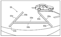
- a vehicle rear line 55 is superimposed on the surrounding image.
- the vehicle rear line 55 is an index line indicating a predetermined position behind the vehicle 30 regardless of the steering angle of the vehicle 30. Therefore, the image is superimposed and displayed at a fixed predetermined position in the peripheral image due to the optical relationship with the camera 12 installed in the vehicle 30.
- the vehicle rear line 55 includes a vehicle width extension line 55a as an extension line of a vehicle width extending in the backward direction of the vehicle, and a 1m reference line 56a as a distance reference line.
- the vehicle rear line 55 is displayed in a color different from the rear prediction line 51, such as green, in order to easily distinguish the vehicle rear line 55 from the rear prediction line 51.
- the vehicle width referred to here is the maximum width in the left-right direction of the vehicle 30, but it may be set wider than the actual maximum width in consideration of safety.
- the indicator line output unit 6 displays the rear prediction line 51 and the vehicle rear line 55 with side lines and shadow lines.
- a side line 51b and a shadow line 51c are attached to the inner side of the pair of left and right prediction trajectory lines 51a of the rear prediction line 51, and the vehicle 30 of the 5m reference line 54a, the 3m reference line 53a, and the 1m caution line 52a.
- Side lines 54b, 53b, and 52b and shadow lines 54c, 53c, and 52c are attached along the side close to.
- side lines 55b and 56b and shadow lines 55c and 56c are attached along the inside of the pair of left and right vehicle width extension lines 55a and the vehicle 30 side of the 1 m reference line in the vehicle rear line 55. In this way, the rear prediction line 51 and the vehicle rear line 55 are displayed in a three-dimensionally superimposed manner on the peripheral image.
- the driver performs steering operation so that the vehicle 30 does not collide with an obstacle such as the parked vehicles 41 and 42 while referring to the rear prediction line 51 and the vehicle rear line 55 superimposed on the surrounding image.
- the vehicle 30 is moved backward to guide the vehicle 30 to the parking space E. Then, when the driver confirms that the vehicle 30 is stored in the parking space E and the vehicle rearward line 55 is substantially parallel to the parking space E, the driver stops the vehicle 30.
- the rear prediction line and the vehicle rear line when the vehicle 30 moves backward have been described, but the present invention is not limited to this.
- the forward prediction line and the vehicle forward line may be superimposed on the surrounding image.
- the predicted trajectory line extends in the forward direction of the vehicle 30 and indicates a predicted trajectory of the movement of the vehicle 30 according to the steering angle.
- the vehicle width extension line indicates an extension line of the vehicle width extending in the forward direction of the vehicle 30.
- the distance guide line indicates a guide of the distance from the front end of the vehicle 30 to the front.
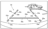
- FIG. 11 shows an example in which a vehicle rear line 55 composed of a vehicle width extension line 55a and a 1 m guide line 56a as a distance guide line is superimposed on the surrounding image.
- the 1 m reference line 56a is displayed as a solid line as in the above-described embodiment, but the vehicle width extension line 55a is displayed as a broken line.
- the index line output unit 6 displays the vehicle rear line 55 with side lines and shadow lines along the side closer to the imaging device (camera 12). That is, the side lines 55b and 56b and the shadow lines 55c and 56c are attached along the inside of the pair of left and right vehicle width extension lines 55a of the vehicle rear line 55 and along the vehicle 30 side of the 1 m reference line 56a. It should be noted that the side line 55b and the shadow line 55c are also displayed as broken lines on the broken line width extension line 55a, and are attached at positions corresponding to the broken line of the line width extension line 55a.
- the vehicle width extension line 55a is displayed in blue, and the 1 m reference line 56a is displayed in red.
- the side line 55b and the shadow line 55c of the vehicle width extension line 55a are also displayed in blue, but the brightness decreases in order of the vehicle width extension line 55a, the side line 55b, and the shadow line 55c, that is, it approaches black.
- the side line 56b and the shadow line 56c of the 1m reference line 56a are displayed in red, but the brightness is set so as to decrease in the order of the 1m reference line 56a, the side line 56b, and the shadow line 56c.
- the present invention is not limited to this, and colors other than those described above, such as yellow, may be used, and the hue itself may be different.
- the vehicle rear line 55 is displayed in a three-dimensional manner superimposed on the surrounding image.
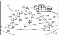
- FIG. 12 shows an example in which a vehicle rear line 55 composed of a vehicle width extension line 55a and a 1m reference line 56a and a 5m reference line 57a as a distance reference line is superimposed and displayed on a peripheral image.
- cross-shaped indexes 55d, 56d, and 57d are intermittently arranged, and a vehicle width extension line 55a and a 1m reference line 56a and a 5m reference line 57a as a distance reference line are drawn.
- the side surface portions 55e, 56e, 57e and the shadow portions are respectively provided on the indicators 55d, 56d, 57d constituting the vehicle width extension line 55a, the 1m reference line 56a, and the 5m reference line 57a.
- 55f, 56f, and 57f are attached.
- the index line output unit 6 displays the index line with the side surface (side surface line) and the shadow portion (shadow line) displayed has been described so far, but the side surface portion (side surface line) and the shadow portion are not necessarily displayed. It is not necessary to display both (shadow lines), and only one of the side part (side line) and the shadow part (shadow line) may be displayed.
- FIGS. 13 to 15 show examples in which the index line output unit 6 displays the index lines with only shadow portions (shadow lines).
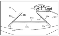
- FIG. 13 shows an example in which shadow lines 55c and 56c are added to the surrounding image and displayed on the vehicle rear line 55 composed of a solid vehicle width extension line 55a and a solid 1m standard line 56a as a distance standard line.
- the index line output unit 6 attaches shadow lines 55c and 56c along the side of the index line that is closer to the imaging device. That is, the shadow lines 55c and 56c are given along the inside of the pair of left and right vehicle width extension lines 55a of the vehicle rear line 55 and the vehicle 30 side of the 1 m reference line 56a.
- FIG. 14 shows an example in which a vehicle rear line composed of a broken vehicle width extension line 55a and a solid 1 m guide line 56a as a distance guide line is superimposed and displayed on a peripheral image. Also in this case, the index line output unit 6 adds a shadow line along the side of the index line that is closer to the imaging device. That is, the shadow lines 55c and 56c are attached along the inside of the pair of left and right vehicle width extension lines 55a of the vehicle rear line 55 and along the vehicle 30 side of the 1 m reference line 56a.
- FIG. 15 shows an example in which cross-shaped indexes 55d, 56d, and 57d are intermittently arranged, and a vehicle width extension line 55a and a 1m reference line 56a and a 5m reference line 57a as distance reference lines are drawn. Show. In this case as well, shadow portions 55f, 56f, and 57f are attached to the indicators 55d, 56d, and 57d constituting the vehicle width extension line 55a, the 1m reference line 56a, and the 5m reference line 57a, respectively.
- FIGS. 16 to 18 show examples in which the index line output unit 6 displays only the side surface (side surface line) on the index line.
- FIG. 16 shows an example in which side lines 55b and 56b are attached to the vehicle rear line 55, which is composed of a solid vehicle width extension line 55a and a solid 1m standard line 56a as a distance standard line, and superimposed on the surrounding images.
- the index line output unit 6 attaches shadow lines 55b and 56b along the side of the index line that is closer to the imaging device. That is, side lines 55b and 56b are attached along the inside of the pair of left and right vehicle width extension lines 55b of the vehicle rear line 55 and along the vehicle 30 side of the 1 m reference line 56b.
- FIG. 17 shows an example in which a vehicle rear line composed of a broken vehicle width extension line 55a and a solid 1 m guide line 56a as a distance guide line is superimposed and displayed on a peripheral image. Also in this case, the index line output unit 6 attaches a side line along the side of the index line that is closer to the imaging device. That is, the shadow lines 55b and 56b are attached along the inside of the pair of left and right vehicle width extension lines 55a of the vehicle rear line 55 and along the vehicle 30 side of the 1 m reference line 56a.
- FIG. 18 shows an example in which cross-shaped indicators 55d, 56d, and 57d are intermittently arranged, and the vehicle width extension line 55a and the 1m reference line 56a and the 5m reference line 57a as the distance reference lines are drawn. Show. In this case as well, side surfaces 55e, 56e and 57e are attached to the indicators 55d, 56d and 57d constituting the vehicle width extension line 55a, the 1m reference line 56a and the 5m reference line 57a, respectively.
- the index line output unit 6 may be configured so that the widths of the index line, the side line, and the shadow line are narrowed as the distance from the camera 12 increases. That is, in the case of the first embodiment described above (see FIGS. 7 to 9), the pair of left and right parking frame lines 61a and 62a extending in the direction along the traveling lane of the vehicle 30, and the parking frame lines 61a and 62a. The side lines 61b and 62b and the shadow lines 61c and 62c attached to are displayed so that the width decreases as the distance from the vehicle 30 increases.
- a pair of parking frame lines 63a and 64a extending in a direction perpendicular to the traveling lane, and side lines 63b and 64b and shadow lines 63c and 64c attached along the parking frame lines 63a and 64a are provided on the vehicle.
- the width of the parking frame line 63a, the side surface line 63b, and the shadow line 63c on the near side is displayed so as to be wider than the width of the parking frame line 64a, the side surface line 64b, and the shadow line 64c on the side far from the vehicle 30. .
- the pair of left and right predicted trajectory lines 51a and the side lines 51b and the shadow lines 51c attached to the predicted trajectory lines 51a of the rear predicted lines 51 are from the vehicle. It is displayed so that the width becomes narrower as the distance increases. In addition, the distance guide line is displayed with a smaller width as the distance guide line is separated from the vehicle 30. In the case of this embodiment, the width of each position guide line is set so that the width becomes narrower in the order of the 1m attention line 52a, the 3m guide line 53a, and the 5m guide line 53a.
- the widths of the side lines 52b, 53b, 54b and the shadow lines 52c, 53c, 54c attached to the position guide line are set to be narrower as the distance from the vehicle 30 increases.
- a pair of left and right vehicle width extension lines 55a, side surface lines 55b, and shadow lines 55c in the vehicle rear line 55 are displayed so that the width becomes narrower as the distance from the vehicle increases.
- the present invention can also be applied to a case in which an index line is superimposed and displayed on a peripheral image in a driving operation other than parking.
- the vehicle periphery display device can easily recognize the index line displayed on the display device, and the driver can clearly recognize the positional relationship between the surrounding image and the index line, thereby assisting the driving operation during parking. It can be applied to a parking assist device.
Landscapes
- Engineering & Computer Science (AREA)
- Mechanical Engineering (AREA)
- Multimedia (AREA)
- Chemical & Material Sciences (AREA)
- Combustion & Propulsion (AREA)
- Transportation (AREA)
- Closed-Circuit Television Systems (AREA)
- Traffic Control Systems (AREA)
- Fittings On The Vehicle Exterior For Carrying Loads, And Devices For Holding Or Mounting Articles (AREA)
Abstract
Description
図1及び図2はこの駐車支援装置を備えた車両30の基本構成を示したものである。運転席に備えられたステアリング24は、パワーステアリングユニット33と連動し、回転操作力を前輪28fに伝えて車両30の操舵を行う。前輪28fは本発明の操舵輪に相当する。車体前部にはエンジン32と、このエンジン32からの動力を変速して前輪28fや後輪28rに伝えるトルクコンバータやCVT等を有する変速機構34とが配置されている。車両30の駆動方式(前輪駆動、後輪駆動、四輪駆動)に応じて、前輪28f及び後輪28rの双方もしくは何れかに動力が伝達される。運転席の近傍には走行速度を制御するアクセル操作手段としてのアクセルペダル26と、前輪28f及び後輪28rのブレーキ装置31を介して前輪28f及び後輪28rに制動力を作用させるブレーキペダル27とが並列配置されている。
(1)第一実施形態では、設定された駐車目標位置に自動操舵により、車両30を誘導する例を示したが、これに限られるものではない。例えば、図10に示すように、周辺画像に指標線として車両の予想進路線を重畳表示して、この進路予想線に基づいて、運転者がステアリング操作等を行って駐車をするようにしてもよい。
Claims (11)
- 車両に設けられた撮影装置により撮影された前記車両の周辺画像を取得する画像取得部と、
車室内に設けられ前記周辺画像を表示する表示装置と、
運転者による運転操作の際に、前記運転者の指標となる指標線を、影部及び前記指標線に隣接する側面部のうち少なくとも一方を付して前記周辺画像に重畳表示させる指標線出力部と、を備えた車両周辺表示装置。 - 前記指標線出力部が、前記側面部に隣接して前記影部を付して表示する請求項1に記載の車両周辺表示装置。
- 前記指標線出力部が、前記指標線のうち前記撮影装置に近い側に前記側面部を付して表示する請求項1または2に記載の車両周辺表示装置。
- 前記指標線出力部が、前記指標線のうち前記撮影装置に近い側に前記影部を付して表示する請求項1~3の何れか一項に記載の車両周辺表示装置。
- 前記指標線が破線である請求項1~4の何れか一項に記載の車両周辺装置。
- 前記指標線が任意の形状の指標を断続的に配置して描画されている請求項1~5の何れか一項に記載の車両周辺表示装置。
- 前記指標線出力部が、前記指標線の幅、及び、前記側面部の幅と前記影部の幅とのうち前記指標線に付されるものの幅を、前記撮影装置からの距離が大きくなるほど狭く表示する請求項1~6の何れか一項に記載の車両周辺表示装置。
- 前記指標線が、駐車スペースを示す駐車枠線である請求項1~7の何れか一項に記載の車両周辺表示装置。
- 前記指標線が、前記車両の走行方向に延在し、舵角に応じた前記車両の移動の予測軌跡を示す予測軌跡線である請求項1~7の何れか一項に記載の車両周辺表示装置。
- 前記指標線が、前記車両の走行方向に延在する車幅の延長線である請求項1~7の何れか一項に記載の車両周辺表示装置。
- 前記指標線が、前記車両の前端から前方への距離、又は、前記車両の後端から後方への距離の目安となる距離目安線である請求項1~7の何れか一項に記載の車両周辺表示装置。
Priority Applications (8)
| Application Number | Priority Date | Filing Date | Title |
|---|---|---|---|
| BRPI0913022A BRPI0913022A2 (pt) | 2008-05-08 | 2009-04-24 | dispositivo de visualização periférica de veículo |
| KR1020107021238A KR101326364B1 (ko) | 2008-05-08 | 2009-04-24 | 차량주변표시장치 |
| EP09742683.7A EP2272716B1 (en) | 2008-05-08 | 2009-04-24 | Vehicle peripheral display device |
| US12/933,994 US20110181724A1 (en) | 2008-05-08 | 2009-04-24 | Vehicle peripheral display device |
| KR1020107021235A KR101238109B1 (ko) | 2008-05-08 | 2009-04-24 | 차량주변표시장치 |
| CN2009801106617A CN101977794B (zh) | 2008-05-08 | 2009-04-24 | 车辆周边显示装置 |
| US12/888,157 US10315568B2 (en) | 2008-05-08 | 2010-09-22 | Vehicle peripheral display device |
| US16/253,451 US10744942B2 (en) | 2008-05-08 | 2019-01-22 | Vehicle peripheral display device |
Applications Claiming Priority (4)
| Application Number | Priority Date | Filing Date | Title |
|---|---|---|---|
| JP2008122557 | 2008-05-08 | ||
| JP2008-122557 | 2008-05-08 | ||
| JP2008276859A JP5636609B2 (ja) | 2008-05-08 | 2008-10-28 | 車両周辺表示装置 |
| JP2008-276859 | 2008-10-28 |
Related Child Applications (2)
| Application Number | Title | Priority Date | Filing Date |
|---|---|---|---|
| US12/933,994 A-371-Of-International US20110181724A1 (en) | 2008-05-08 | 2009-04-24 | Vehicle peripheral display device |
| US12/888,157 Division US10315568B2 (en) | 2008-05-08 | 2010-09-22 | Vehicle peripheral display device |
Publications (1)
| Publication Number | Publication Date |
|---|---|
| WO2009136559A1 true WO2009136559A1 (ja) | 2009-11-12 |
Family
ID=41264614
Family Applications (1)
| Application Number | Title | Priority Date | Filing Date |
|---|---|---|---|
| PCT/JP2009/058193 Ceased WO2009136559A1 (ja) | 2008-05-08 | 2009-04-24 | 車両周辺表示装置 |
Country Status (7)
| Country | Link |
|---|---|
| US (3) | US20110181724A1 (ja) |
| EP (2) | EP2272716B1 (ja) |
| JP (1) | JP5636609B2 (ja) |
| KR (2) | KR101238109B1 (ja) |
| CN (2) | CN101982348A (ja) |
| BR (1) | BRPI0913022A2 (ja) |
| WO (1) | WO2009136559A1 (ja) |
Cited By (7)
| Publication number | Priority date | Publication date | Assignee | Title |
|---|---|---|---|---|
| WO2012028230A1 (de) * | 2010-09-02 | 2012-03-08 | Daimler Ag | Verfahren zum darstellen von hifslinien in einem kamerabasierten fahrerassistenzsystem |
| CN102696225A (zh) * | 2010-01-19 | 2012-09-26 | 爱信精机株式会社 | 车辆周边监视装置 |
| US8633811B2 (en) | 2009-05-18 | 2014-01-21 | Aisin Seiki Kabushiki Kaisha | Driving assist apparatus |
| CN103692973A (zh) * | 2012-09-27 | 2014-04-02 | 富士通天株式会社 | 图像生成装置、图像显示系统、以及图像生成方法 |
| JP2016095673A (ja) * | 2014-11-14 | 2016-05-26 | アイシン・エィ・ダブリュ株式会社 | 車両情報案内システム、車両情報案内方法及びコンピュータプログラム |
| JP2022064677A (ja) * | 2020-10-14 | 2022-04-26 | 株式会社デンソー | 表示制御装置、表示装置及び表示制御プログラム |
| JP2025013519A (ja) * | 2021-03-24 | 2025-01-24 | ソニーグループ株式会社 | 情報処理装置、および情報処理方法、並びにプログラム |
Families Citing this family (31)
| Publication number | Priority date | Publication date | Assignee | Title |
|---|---|---|---|---|
| JP5636609B2 (ja) | 2008-05-08 | 2014-12-10 | アイシン精機株式会社 | 車両周辺表示装置 |
| JP5618139B2 (ja) * | 2010-09-21 | 2014-11-05 | アイシン精機株式会社 | 駐車支援装置 |
| US9363485B2 (en) | 2011-01-27 | 2016-06-07 | Kyocera Corporation | Vehicle driving assist device |
| DE102011105884B4 (de) | 2011-06-28 | 2019-02-21 | Volkswagen Aktiengesellschaft | Verfahren und Vorrichtung zum Einparken eines Fahrzeugs |
| JP5858045B2 (ja) * | 2011-09-13 | 2016-02-10 | トヨタ自動車株式会社 | 車載カメラの光軸把握装置 |
| JP5516561B2 (ja) * | 2011-12-08 | 2014-06-11 | 株式会社デンソーアイティーラボラトリ | 車両用運転支援装置 |
| WO2013086249A2 (en) | 2011-12-09 | 2013-06-13 | Magna Electronics, Inc. | Vehicle vision system with customized display |
| JP2013224081A (ja) * | 2012-04-20 | 2013-10-31 | Kyocera Corp | 画像処理装置および走行支援方法 |
| CN104995054B (zh) * | 2013-01-11 | 2018-07-17 | 日产自动车株式会社 | 车辆用显示控制装置和车辆用显示控制方法 |
| CN104118357B (zh) * | 2013-04-25 | 2018-03-09 | 深圳市豪恩汽车电子装备股份有限公司 | 一种倒车轨迹线生成方法、装置及倒车引导器 |
| CN104071074A (zh) * | 2014-06-17 | 2014-10-01 | 张亦卫 | 能为后车提供视野的汽车 |
| JP6327160B2 (ja) * | 2014-09-02 | 2018-05-23 | 株式会社デンソー | 車両用画像処理装置 |
| KR102214604B1 (ko) * | 2014-09-05 | 2021-02-10 | 현대모비스 주식회사 | 운전 보조 영상 표시 방법 |
| USD760247S1 (en) * | 2014-12-30 | 2016-06-28 | Toyota Jidosha Kabushiki Kaisha | Display screen with graphical user interface |
| USD758390S1 (en) * | 2014-12-30 | 2016-06-07 | Toyota Jidosha Kabushiki Kaisha | Display screen with graphical user interface |
| KR101876032B1 (ko) * | 2016-06-27 | 2018-08-02 | 현대자동차주식회사 | 주차구획 표시 장치 및 그 방법 |
| CN106043126A (zh) * | 2016-07-28 | 2016-10-26 | 江苏罗思韦尔电气有限公司 | 一种重型卡车转向预警辅助装置及预警方法 |
| WO2018105417A1 (ja) | 2016-12-09 | 2018-06-14 | 京セラ株式会社 | 撮像装置、画像処理装置、表示システム、および車両 |
| CN107512223A (zh) * | 2017-08-02 | 2017-12-26 | 太仓美宅姬娱乐传媒有限公司 | 一种侧方位停车影像辅助系统 |
| JP7201315B2 (ja) * | 2017-11-08 | 2023-01-10 | トヨタ自動車株式会社 | 電子ミラー装置 |
| GB2568749B (en) * | 2017-11-28 | 2020-09-02 | Jaguar Land Rover Ltd | Imaging apparatus and method |
| JP7037926B2 (ja) * | 2017-12-04 | 2022-03-17 | アルパイン株式会社 | 運転支援システムおよび後方ガイド画像の生成方法 |
| JP2019154018A (ja) * | 2018-03-06 | 2019-09-12 | パナソニックIpマネジメント株式会社 | 車両周辺表示システム、表示制御装置およびコンピュータプログラム |
| JP6964276B2 (ja) * | 2018-03-07 | 2021-11-10 | パナソニックIpマネジメント株式会社 | 表示制御装置、車両周辺表示システムおよびコンピュータプログラム |
| JP7113348B2 (ja) * | 2018-03-15 | 2022-08-05 | パナソニックIpマネジメント株式会社 | 車両周辺表示システム、表示制御装置およびコンピュータプログラム |
| JP7209189B2 (ja) * | 2019-03-25 | 2023-01-20 | パナソニックIpマネジメント株式会社 | 画像生成装置、カメラ、表示システム、車両及び画像生成方法 |
| WO2021155914A1 (en) * | 2020-02-04 | 2021-08-12 | Volvo Truck Corporation | Method for adapting an overlaid image of an area located rearwards and along a vehicle side |
| WO2022016444A1 (zh) * | 2020-07-23 | 2022-01-27 | 华为技术有限公司 | 一种画面显示方法、智能车、存储介质以及装置 |
| JP7491194B2 (ja) * | 2020-11-23 | 2024-05-28 | 株式会社デンソー | 周辺画像生成装置、表示制御方法 |
| JP2022154517A (ja) * | 2021-03-30 | 2022-10-13 | パナソニックIpマネジメント株式会社 | 駐車支援装置および駐車支援方法 |
| CN116489318B (zh) * | 2023-06-25 | 2023-08-22 | 北京易控智驾科技有限公司 | 自动驾驶车辆的远程驾驶方法和装置 |
Citations (13)
| Publication number | Priority date | Publication date | Assignee | Title |
|---|---|---|---|---|
| JPS6414700U (ja) * | 1987-07-18 | 1989-01-25 | ||
| JPH11334470A (ja) | 1998-05-22 | 1999-12-07 | Aisin Seiki Co Ltd | 駐車補助装置 |
| JP2001010428A (ja) * | 1999-06-29 | 2001-01-16 | Fujitsu Ten Ltd | 車両の運転支援装置 |
| JP2001180405A (ja) * | 1999-12-28 | 2001-07-03 | Toyota Autom Loom Works Ltd | 操舵支援装置 |
| JP2002160597A (ja) * | 2000-11-28 | 2002-06-04 | Mitsubishi Motors Corp | 駐車支援装置 |
| JP2002314991A (ja) * | 2001-02-09 | 2002-10-25 | Matsushita Electric Ind Co Ltd | 画像合成装置 |
| JP2004056219A (ja) * | 2002-07-16 | 2004-02-19 | Nissan Motor Co Ltd | 車両周辺監視装置 |
| JP2004147083A (ja) * | 2002-10-24 | 2004-05-20 | Matsushita Electric Ind Co Ltd | 運転支援装置 |
| JP2004284370A (ja) * | 2003-01-29 | 2004-10-14 | Toyota Industries Corp | 駐車支援装置 |
| JP2004345554A (ja) * | 2003-05-23 | 2004-12-09 | Clarion Co Ltd | 車両後方モニタ装置及び車両後方モニタシステム |
| JP2005045602A (ja) * | 2003-07-23 | 2005-02-17 | Matsushita Electric Works Ltd | 車両用視界モニタシステム |
| JP2006040008A (ja) * | 2004-07-28 | 2006-02-09 | Auto Network Gijutsu Kenkyusho:Kk | 運転支援装置 |
| JP2006284458A (ja) * | 2005-04-01 | 2006-10-19 | Denso Corp | 運転支援情報表示システム |
Family Cites Families (16)
| Publication number | Priority date | Publication date | Assignee | Title |
|---|---|---|---|---|
| JPS6414700A (en) | 1987-07-08 | 1989-01-18 | Aisin Aw Co | Device for displaying prospective track of vehicle |
| JP3391311B2 (ja) * | 1999-05-12 | 2003-03-31 | 株式会社デンソー | 地図表示装置 |
| US7366595B1 (en) * | 1999-06-25 | 2008-04-29 | Seiko Epson Corporation | Vehicle drive assist system |
| US6487481B2 (en) * | 2000-05-30 | 2002-11-26 | Aisin Seiki Kabushiki Kaisha | Parking assisting apparatus |
| EP1168248A3 (en) * | 2000-06-30 | 2003-12-10 | Matsushita Electric Industrial Co., Ltd. | Rendering device |
| JP4473963B2 (ja) * | 2001-01-26 | 2010-06-02 | アルパイン株式会社 | ナビゲーション装置 |
| JP3800172B2 (ja) * | 2002-12-24 | 2006-07-26 | トヨタ自動車株式会社 | 車両用周辺監視装置 |
| EP1717757A1 (de) * | 2005-04-28 | 2006-11-02 | Bayerische Motoren Werke Aktiengesellschaft | Verfahren zur grafischen Darstellung der Umgebung eines Kraftfahrzeugs |
| JP4561479B2 (ja) * | 2005-05-26 | 2010-10-13 | アイシン・エィ・ダブリュ株式会社 | 駐車支援方法及び駐車支援装置 |
| JP4661658B2 (ja) * | 2006-03-30 | 2011-03-30 | アイシン・エィ・ダブリュ株式会社 | 運転支援方法、運転支援装置及び運転支援プログラム |
| JP2007333502A (ja) * | 2006-06-14 | 2007-12-27 | Nissan Motor Co Ltd | 合流支援装置及び合流支援方法 |
| JP5217152B2 (ja) * | 2006-11-14 | 2013-06-19 | アイシン精機株式会社 | 車両周辺表示装置 |
| JP4899826B2 (ja) * | 2006-11-28 | 2012-03-21 | アイシン・エィ・ダブリュ株式会社 | 駐車支援方法及び駐車支援装置 |
| US8218007B2 (en) * | 2007-09-23 | 2012-07-10 | Volkswagen Ag | Camera system for a vehicle and method for controlling a camera system |
| JP5636609B2 (ja) * | 2008-05-08 | 2014-12-10 | アイシン精機株式会社 | 車両周辺表示装置 |
| JP2012106732A (ja) | 2011-11-25 | 2012-06-07 | Aisin Seiki Co Ltd | 車両周辺表示装置 |
-
2008
- 2008-10-28 JP JP2008276859A patent/JP5636609B2/ja active Active
-
2009
- 2009-04-24 KR KR1020107021235A patent/KR101238109B1/ko not_active Expired - Fee Related
- 2009-04-24 WO PCT/JP2009/058193 patent/WO2009136559A1/ja not_active Ceased
- 2009-04-24 CN CN2010105435302A patent/CN101982348A/zh active Pending
- 2009-04-24 EP EP09742683.7A patent/EP2272716B1/en not_active Not-in-force
- 2009-04-24 EP EP10178606.9A patent/EP2287044B1/en not_active Not-in-force
- 2009-04-24 US US12/933,994 patent/US20110181724A1/en not_active Abandoned
- 2009-04-24 BR BRPI0913022A patent/BRPI0913022A2/pt not_active IP Right Cessation
- 2009-04-24 CN CN2009801106617A patent/CN101977794B/zh not_active Expired - Fee Related
- 2009-04-24 KR KR1020107021238A patent/KR101326364B1/ko active Active
-
2010
- 2010-09-22 US US12/888,157 patent/US10315568B2/en not_active Expired - Fee Related
-
2019
- 2019-01-22 US US16/253,451 patent/US10744942B2/en active Active
Patent Citations (13)
| Publication number | Priority date | Publication date | Assignee | Title |
|---|---|---|---|---|
| JPS6414700U (ja) * | 1987-07-18 | 1989-01-25 | ||
| JPH11334470A (ja) | 1998-05-22 | 1999-12-07 | Aisin Seiki Co Ltd | 駐車補助装置 |
| JP2001010428A (ja) * | 1999-06-29 | 2001-01-16 | Fujitsu Ten Ltd | 車両の運転支援装置 |
| JP2001180405A (ja) * | 1999-12-28 | 2001-07-03 | Toyota Autom Loom Works Ltd | 操舵支援装置 |
| JP2002160597A (ja) * | 2000-11-28 | 2002-06-04 | Mitsubishi Motors Corp | 駐車支援装置 |
| JP2002314991A (ja) * | 2001-02-09 | 2002-10-25 | Matsushita Electric Ind Co Ltd | 画像合成装置 |
| JP2004056219A (ja) * | 2002-07-16 | 2004-02-19 | Nissan Motor Co Ltd | 車両周辺監視装置 |
| JP2004147083A (ja) * | 2002-10-24 | 2004-05-20 | Matsushita Electric Ind Co Ltd | 運転支援装置 |
| JP2004284370A (ja) * | 2003-01-29 | 2004-10-14 | Toyota Industries Corp | 駐車支援装置 |
| JP2004345554A (ja) * | 2003-05-23 | 2004-12-09 | Clarion Co Ltd | 車両後方モニタ装置及び車両後方モニタシステム |
| JP2005045602A (ja) * | 2003-07-23 | 2005-02-17 | Matsushita Electric Works Ltd | 車両用視界モニタシステム |
| JP2006040008A (ja) * | 2004-07-28 | 2006-02-09 | Auto Network Gijutsu Kenkyusho:Kk | 運転支援装置 |
| JP2006284458A (ja) * | 2005-04-01 | 2006-10-19 | Denso Corp | 運転支援情報表示システム |
Non-Patent Citations (1)
| Title |
|---|
| See also references of EP2272716A4 |
Cited By (11)
| Publication number | Priority date | Publication date | Assignee | Title |
|---|---|---|---|---|
| US8633811B2 (en) | 2009-05-18 | 2014-01-21 | Aisin Seiki Kabushiki Kaisha | Driving assist apparatus |
| CN102696225A (zh) * | 2010-01-19 | 2012-09-26 | 爱信精机株式会社 | 车辆周边监视装置 |
| CN102696225B (zh) * | 2010-01-19 | 2014-10-08 | 爱信精机株式会社 | 车辆周边监视装置 |
| WO2012028230A1 (de) * | 2010-09-02 | 2012-03-08 | Daimler Ag | Verfahren zum darstellen von hifslinien in einem kamerabasierten fahrerassistenzsystem |
| CN103692973A (zh) * | 2012-09-27 | 2014-04-02 | 富士通天株式会社 | 图像生成装置、图像显示系统、以及图像生成方法 |
| JP2016095673A (ja) * | 2014-11-14 | 2016-05-26 | アイシン・エィ・ダブリュ株式会社 | 車両情報案内システム、車両情報案内方法及びコンピュータプログラム |
| JP2022064677A (ja) * | 2020-10-14 | 2022-04-26 | 株式会社デンソー | 表示制御装置、表示装置及び表示制御プログラム |
| JP7503995B2 (ja) | 2020-10-14 | 2024-06-21 | 株式会社デンソー | 表示制御装置、表示装置及び表示制御プログラム |
| JP2025013519A (ja) * | 2021-03-24 | 2025-01-24 | ソニーグループ株式会社 | 情報処理装置、および情報処理方法、並びにプログラム |
| JP7824380B2 (ja) | 2021-03-24 | 2026-03-04 | ソニーグループ株式会社 | 情報処理装置、および情報処理方法、並びにプログラム |
| US12620311B2 (en) | 2021-03-24 | 2026-05-05 | Sony Group Corporation | Information processing apparatus, information processing method, and program |
Also Published As
| Publication number | Publication date |
|---|---|
| CN101982348A (zh) | 2011-03-02 |
| EP2272716A4 (en) | 2012-04-25 |
| JP5636609B2 (ja) | 2014-12-10 |
| EP2272716B1 (en) | 2013-07-24 |
| US10315568B2 (en) | 2019-06-11 |
| CN101977794A (zh) | 2011-02-16 |
| US20110069169A1 (en) | 2011-03-24 |
| KR101238109B1 (ko) | 2013-02-27 |
| EP2272716A1 (en) | 2011-01-12 |
| EP2287044A3 (en) | 2012-04-25 |
| JP2009292457A (ja) | 2009-12-17 |
| KR20100120695A (ko) | 2010-11-16 |
| KR101326364B1 (ko) | 2013-11-11 |
| BRPI0913022A2 (pt) | 2015-10-13 |
| EP2287044B1 (en) | 2015-09-23 |
| KR20100120694A (ko) | 2010-11-16 |
| CN101977794B (zh) | 2013-04-17 |
| US10744942B2 (en) | 2020-08-18 |
| US20110181724A1 (en) | 2011-07-28 |
| US20190152394A1 (en) | 2019-05-23 |
| EP2287044A2 (en) | 2011-02-23 |
Similar Documents
| Publication | Publication Date | Title |
|---|---|---|
| JP5636609B2 (ja) | 車両周辺表示装置 | |
| JP4623395B2 (ja) | 車両周辺表示装置 | |
| JP4853712B2 (ja) | 駐車支援装置 | |
| CN101631695B (zh) | 驻车辅助装置 | |
| US8793053B2 (en) | Vehicle periphery monitoring device | |
| JP5429514B2 (ja) | 駐車支援装置 | |
| JP5182545B2 (ja) | 駐車支援装置 | |
| EP2253529B1 (en) | Driving assist apparatus | |
| EP2910423B1 (en) | Surroundings monitoring apparatus and program thereof | |
| JP2009292339A (ja) | 駐車支援装置 | |
| JP2011151479A5 (ja) | ||
| CN110546047A (zh) | 停车辅助装置 |
Legal Events
| Date | Code | Title | Description |
|---|---|---|---|
| WWE | Wipo information: entry into national phase |
Ref document number: 200980110661.7 Country of ref document: CN |
|
| 121 | Ep: the epo has been informed by wipo that ep was designated in this application |
Ref document number: 09742683 Country of ref document: EP Kind code of ref document: A1 |
|
| WWE | Wipo information: entry into national phase |
Ref document number: 2009742683 Country of ref document: EP |
|
| ENP | Entry into the national phase |
Ref document number: 20107021235 Country of ref document: KR Kind code of ref document: A |
|
| NENP | Non-entry into the national phase |
Ref country code: DE |
|
| WWE | Wipo information: entry into national phase |
Ref document number: 8240/DELNP/2010 Country of ref document: IN |
|
| WWE | Wipo information: entry into national phase |
Ref document number: 12933994 Country of ref document: US |
|
| ENP | Entry into the national phase |
Ref document number: PI0913022 Country of ref document: BR Kind code of ref document: A2 Effective date: 20101108 |