WO2009139253A1 - 変倍光学系、この変倍光学系を備えた光学機器、及び、変倍光学系の製造方法 - Google Patents
変倍光学系、この変倍光学系を備えた光学機器、及び、変倍光学系の製造方法 Download PDFInfo
- Publication number
- WO2009139253A1 WO2009139253A1 PCT/JP2009/057504 JP2009057504W WO2009139253A1 WO 2009139253 A1 WO2009139253 A1 WO 2009139253A1 JP 2009057504 W JP2009057504 W JP 2009057504W WO 2009139253 A1 WO2009139253 A1 WO 2009139253A1
- Authority
- WO
- WIPO (PCT)
- Prior art keywords
- lens group
- lens
- end state
- wide
- optical system
- Prior art date
- Legal status (The legal status is an assumption and is not a legal conclusion. Google has not performed a legal analysis and makes no representation as to the accuracy of the status listed.)
- Ceased
Links
Images











Classifications
-
- G—PHYSICS
- G02—OPTICS
- G02B—OPTICAL ELEMENTS, SYSTEMS OR APPARATUS
- G02B27/00—Optical systems or apparatus not provided for by any of the groups G02B1/00 - G02B26/00, G02B30/00
- G02B27/64—Imaging systems using optical elements for stabilisation of the lateral and angular position of the image
- G02B27/646—Imaging systems using optical elements for stabilisation of the lateral and angular position of the image compensating for small deviations, e.g. due to vibration or shake
-
- G—PHYSICS
- G02—OPTICS
- G02B—OPTICAL ELEMENTS, SYSTEMS OR APPARATUS
- G02B15/00—Optical objectives with means for varying the magnification
- G02B15/14—Optical objectives with means for varying the magnification by axial movement of one or more lenses or groups of lenses relative to the image plane for continuously varying the equivalent focal length of the objective
- G02B15/144—Optical objectives with means for varying the magnification by axial movement of one or more lenses or groups of lenses relative to the image plane for continuously varying the equivalent focal length of the objective having four groups only
- G02B15/1441—Optical objectives with means for varying the magnification by axial movement of one or more lenses or groups of lenses relative to the image plane for continuously varying the equivalent focal length of the objective having four groups only the first group being positive
- G02B15/144113—Optical objectives with means for varying the magnification by axial movement of one or more lenses or groups of lenses relative to the image plane for continuously varying the equivalent focal length of the objective having four groups only the first group being positive arranged +-++
-
- G—PHYSICS
- G03—PHOTOGRAPHY; CINEMATOGRAPHY; ANALOGOUS TECHNIQUES USING WAVES OTHER THAN OPTICAL WAVES; ELECTROGRAPHY; HOLOGRAPHY
- G03B—APPARATUS OR ARRANGEMENTS FOR TAKING PHOTOGRAPHS OR FOR PROJECTING OR VIEWING THEM; APPARATUS OR ARRANGEMENTS EMPLOYING ANALOGOUS TECHNIQUES USING WAVES OTHER THAN OPTICAL WAVES; ACCESSORIES THEREFOR
- G03B5/00—Adjustment of optical system relative to image or object surface other than for focusing
Definitions
- the present invention relates to a variable magnification optical system, an optical apparatus including the variable magnification optical system, and a method for manufacturing the variable magnification optical system.
- the present invention has been made in view of such a problem, and a variable power optical system capable of achieving good optical performance, an optical apparatus including the variable power optical system, and manufacture of the variable power optical system It aims to provide a method.
- a variable magnification optical system includes, in order from the object side, a first lens group having a positive refractive power, a second lens group having a negative refractive power, and a positive refraction.
- a third lens group having a positive power and a fourth lens group having a positive refractive power when zooming from the wide-angle end state to the telephoto end state, the first lens group and the second lens group The distance increases, the distance between the second lens group and the third lens group decreases, the distance between the third lens group and the fourth lens group changes, and a part of the third lens group is orthogonal to the optical axis. Configured to move in the direction of.
- the focal length of the entire system in the wide-angle end state is fw
- the focal length of the entire system in the telephoto end state is ft
- the focal length of the third lens group is f3
- the lens position state from the wide-angle end state to the telephoto end state is ⁇ d1
- the total length in the wide-angle end state is Lw
- the following expression 0.25 ⁇ (Lw ⁇ fw) / ( ⁇ d1 ⁇ ft) ⁇ 0 .55 2.20 ⁇ f3 / fw ⁇ 4.50 It is configured to satisfy the following conditions.
- the third lens group includes, in order from the object side, a 3a lens group having positive refractive power and a 3b lens group having negative refractive power, and 3b
- the lens group may be configured to move in a direction orthogonal to the optical axis.
- variable magnification optical system when the focal length of the first lens unit is f1, the following expression 3.50 ⁇ f1 / fw ⁇ 8.00 The above condition may be satisfied.
- the third lens group and the fourth lens group may move in the object direction when the lens position changes from the wide-angle end state to the telephoto end state.
- the first lens unit may move in the object direction when the lens position changes from the wide-angle end state to the telephoto end state.
- the distance between the third lens group and the fourth lens group in the wide-angle end state is configured to be larger than the distance between the third lens group and the fourth lens group in the telephoto end state. It may be.
- the 3b lens group may be composed of a cemented lens in which, in order from the object side, a biconcave lens and a positive meniscus lens having a convex surface facing the object side are cemented.
- the most object side lens surface of the 3b lens group may be formed in an aspherical shape.
- an optical apparatus includes the above-described variable magnification optical system.
- a variable magnification optical system includes, in order from the object side, a first lens group having a positive refractive power, a second lens group having a negative refractive power, and a positive And a fourth lens group having a positive refractive power, and when zooming from the wide-angle end state to the telephoto end state, the first lens group and the second lens group Increases, the distance between the second lens group and the third lens group decreases, the distance between the third lens group and the fourth lens group changes, and part of the third lens group has an optical axis.
- the focal length of the entire system in the wide-angle end state is fw
- the focal length of the entire system in the telephoto end state is ft
- the focal length of the third lens group is f3.
- Movement on the optical axis of the first lens group when the lens position changes from the end state to the telephoto end state is ⁇ d1
- the movement distance on the optical axis of the third lens group when the lens position changes from the wide-angle end state to the telephoto end state is ⁇ d3
- the total length in the wide-angle end state is Lw, .15 ⁇ (Lw ⁇ fw) / ( ⁇ d1 ⁇ ft) ⁇ 0.58 0.42 ⁇ (Lw ⁇ fw) / ( ⁇ d3 ⁇ ft) ⁇ 0.90 2.20 ⁇ f3 / fw ⁇ 4.50 It is configured to satisfy the following conditions.
- the variable magnification optical system manufacturing method has, in order from the object side, a first lens group having a positive refractive power, a second lens group having a negative refractive power, and a positive refractive power.
- a focal length of the entire system in the wide-angle end state is fw
- a focal length of the entire system in the telephoto end state is ft
- a focal length of the third lens group is f3
- From the wide-angle end state On the optical axis of the first lens group when the lens position changes to the telephoto end state
- the distance traveled by the [Delta] d1 when the total length in the wide-angle end state and Lw, the formula 0.25 ⁇ (Lw ⁇ fw) / ( ⁇ d1 ⁇ ft) ⁇ 0.55 2.20 ⁇ f3 / fw ⁇ 4.50 Satisfy the conditions.
- variable optical performance can be achieved by configuring the variable power optical system according to the present invention, the optical apparatus equipped with the variable power optical system, and the manufacturing method of the variable power optical system as described above.
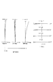
- FIG. 4A is a diagram illustrating various aberrations in the infinitely focused state according to the first example
- FIG. 5A is a diagram illustrating various aberrations in the wide-angle end state
- FIG. FIG. 7 is a coma aberration diagram when shake correction is performed for rotational shake.
- FIG. 6 is an aberration diagram in an infinitely focused state at an intermediate focal length state in the first example.
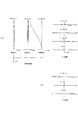
- FIG. 4A is a diagram illustrating various aberrations in the infinitely focused state according to the first embodiment
- FIG. 5A is a diagram illustrating various aberrations in the telephoto end state
- FIG. 7 is a coma aberration diagram when shake correction is performed for rotational shake. It is sectional drawing which shows the structure of the variable magnification optical system by 2nd Example.
- FIG. 7A is a diagram illustrating various aberrations in the infinitely focused state according to the second embodiment
- FIG. 9A is a diagram illustrating various aberrations in the wide-angle end state
- FIG. 9B is 0.60 ° in the infinity photographing state in the wide-angle end state.
- FIG. 7 is a coma aberration diagram when shake correction is performed for rotational shake. It is an aberration diagram of the infinite focus state in the intermediate focal length state of the second embodiment.
- FIG. 7 is a coma aberration diagram when shake correction is performed for rotational shake. It is an aberration diagram of the infinite focus state in the intermediate focal length state of the second embodiment.
- FIG. 7A is a diagram illustrating various aberrations in the infinite focus state according to the second embodiment
- FIG. 9A is a diagram illustrating various aberrations in the telephoto end state
- FIG. 9B is 0.27 ° in the infinity photographing state in the telephoto end state.
- FIG. 7 is a coma aberration diagram when shake correction is performed for rotational shake. It is sectional drawing which shows the structure of the variable magnification optical system by 3rd Example.
- FIG. 6A is a diagram illustrating various aberrations in the infinite focus state according to the third example
- FIG. 6A is a diagram illustrating various aberrations in the wide-angle end state
- FIG. FIG. 7 is a coma aberration diagram when shake correction is performed for rotational shake.
- FIG. 6A is a diagram illustrating various aberrations in the infinitely focused state according to the third embodiment
- FIG. 9A is a diagram illustrating various aberrations in the telephoto end state
- FIG. 9B is 0.30 ° in the infinity photographing state in the telephoto end state
- FIG. 7 is a coma aberration diagram when shake correction is performed for rotational shake. It is sectional drawing which shows the structure of the variable magnification optical system by 4th Example.
- FIG. 6A is a diagram illustrating various aberrations in the infinitely focused state according to the fourth example
- FIG. 6A is a diagram illustrating various aberrations in the wide-angle end state
- FIG. 7 is a coma aberration diagram when shake correction is performed for rotational shake.
- FIG. 10 is an aberration diagram in an infinitely focused state at an intermediate focal length state in the fourth example.
- FIG. 7A is a diagram illustrating various aberrations in the infinite focus state according to the fourth embodiment
- FIG. 9A is a diagram illustrating various aberrations in the telephoto end state
- FIG. 9B is 0.30 ° in the infinity photographing state in the telephoto end state.
- FIG. 7 is a coma aberration diagram when shake correction is performed for rotational shake. It is sectional drawing which shows the structure of the variable magnification optical system by 5th Example.
- FIG. 9A is a diagram illustrating various aberrations in the infinitely focused state according to the fifth example, FIG.
- FIG. 9A is a diagram illustrating various aberrations in the wide-angle end state
- FIG. 9B is 0.60 ° in the infinity photographing state in the wide-angle end state.
- FIG. 7 is a coma aberration diagram when shake correction is performed for rotational shake.
- FIG. 10 is an aberration diagram in an infinitely focused state at an intermediate focal length state in the fifth example.
- FIG. 7A is a diagram illustrating various aberrations in the infinitely focused state according to the fifth example
- FIG. 9A is a diagram illustrating various aberrations in the telephoto end state
- FIG. 9B is 0.27 ° in the infinity photographing state in the telephoto end state.
- FIG. 7 is a coma aberration diagram when shake correction is performed for rotational shake.
- FIG. 9A is a diagram illustrating various aberrations in the infinitely focused state according to the sixth example
- FIG. 9A is a diagram illustrating various aberrations in the wide-angle end state
- FIG. 7 is a coma aberration diagram when shake correction is performed for rotational shake. It is an aberration diagram of the infinity focus state in the intermediate focal length state of the sixth example.
- FIG. 10A is a diagram illustrating various aberrations in the infinite focus state according to the sixth example, FIG.
- FIG. 10A is a diagram illustrating various aberrations in the telephoto end state
- FIG. 9B is 0.30 ° in the infinity photographing state in the telephoto end state
- FIG. 7 is a coma aberration diagram when shake correction is performed for rotational shake. It is a flowchart of the manufacturing method of the variable magnification optical system which concerns on embodiment.
- ZL ZL1 to ZL6 ... variable power optical system
- G1 ... first lens group
- G2 ... second lens group
- G3 ... third lens group
- G3a ... third a lens group
- G3b ... third b lens group
- G4 ... first 4 lens groups
- 1 ... Digital SLR camera (optical equipment)
- variable magnification optical system ZL includes, in order from the object side, a first lens group G1 having a positive refractive power, a second lens group G2 having a negative refractive power, and a positive refractive power. And a fourth lens group G4 having a positive refractive power.
- the lens position changes from the wide-angle end state to the telephoto end state
- the distance between the first lens group G1 and the second lens group G2 increases, and the second lens group G2 and the third lens group G3
- the distance decreases, the distance between the third lens group G3 and the fourth lens group G4 changes, and a part of the third lens group G3 is configured to move in a direction orthogonal to the optical axis.
- the third lens group G3 includes, in order from the object side, a third a lens group G3a having a positive refractive power and a third b lens group G3b having a negative refractive power.
- a third lens group G3a having a positive refractive power
- a third b lens group G3b having a negative refractive power.
- the third lens group G3 includes a third lens group G3a having a positive refractive power and a third lens group G3b having a negative refractive power, and the third lens group G3b is used as a vibration-proof lens group. By using it, it is possible to reduce the size of the vibration isolation mechanism and reduce the mass of the vibration isolation lens group. In addition, with such a refractive power distribution, it is possible to reduce degradation in imaging performance when the anti-vibration 3b lens group G3b is moved in a direction orthogonal to the optical axis.
- the third lens group G3b is preferably composed of a cemented lens in which, in order from the object side, a biconcave lens and a positive meniscus lens having a convex surface directed toward the object side are cemented.
- the most object side lens surface of the third lens group G3b be formed in an aspherical shape. Therefore, even when the third b lens group G3b is decentered (that is, when it is moved during image stabilization), the deterioration of the decentration coma aberration can be sufficiently reduced.
- the zoom optical system ZL it is desirable that the third lens group G3 and the fourth lens group G4 move in the object direction when the lens position changes from the wide-angle end state to the telephoto end state.
- the moving mechanism for moving each lens group can have a simple configuration, and the variable magnification optical system ZL can be reduced in size, and the overall length of the lens barrel having the variable magnification optical system ZL is shortened. It becomes possible.
- variable magnification optical system ZL it is desirable that the first lens group G1 moves in the object direction when the lens position changes from the wide-angle end state to the telephoto end state.
- the moving mechanism for moving each lens group can have a simple configuration and the entire length can be reduced.
- the distance between the third lens group G3 and the fourth lens group G4 in the wide-angle end state is larger than the distance between the third lens group G3 and the fourth lens group G4 in the telephoto end state. It is desirable to be configured as follows. Thereby, field curvature at the time of shifting from the wide-angle end state to the telephoto end state can be suppressed.
- the focal length of the entire system in the wide-angle end state is fw
- the focal length of the entire system in the telephoto end state is ft
- the focal length of the third lens group G3 is f3.
- the movement distance on the optical axis of the first lens group G1 when the lens position state changes from the end state to the telephoto end state is ⁇ d1
- the third lens when the lens position state changes from the wide-angle end state to the telephoto end state It is desirable to satisfy the following conditional expressions (1), (2), and (3) where ⁇ d3 is the moving distance on the optical axis of the group G3 and Lw is the total length in the wide-angle end state.
- Conditional expression (1) prescribes a full length range suitable for ensuring imaging performance by zoom magnification. If the upper limit of conditional expression (1) is exceeded, the total length at the wide-angle end becomes large, the diameter of the lens arranged closest to the object side becomes large, and the height of the off-axis rays increases. Correction of aberration and curvature of field becomes difficult, and distortion at the telephoto end increases to the plus side, which is not preferable.
- the upper limit value of conditional expression (1) is preferably 0.55, 0.50, and 0.48.
- conditional expression (1) is preferably 0.20, 0.25, 0.30.
- Conditional expression (2) defines the moving distance of the third lens group G3 according to the zoom magnification. If the upper limit of conditional expression (2) is exceeded, the moving amount of the third lens group G3 decreases, the moving amount of the first lens group G1 increases, and the total length at the telephoto end increases. Alternatively, the amount of movement of the fourth lens group G4 increases and it becomes difficult to ensure the back focus. Further, it is not preferable because the decentration coma when the decentering occurs between the third lens group G3 and the fourth lens group G4 due to a manufacturing error increases and it becomes difficult to correct the deterioration of the imaging performance.
- the upper limit value of conditional expression (2) is preferably 0.81, 0.75, and 0.62.
- the focal length of the third lens group G3 increases and the amount of movement increases. This is not preferable because the correction movement amount of the third lens group G3b at the time of image stabilization is increased and the size of the image stabilization mechanism is increased. In order to mitigate this influence, it is not preferable to reduce the focal lengths of the first lens group G1 and the second lens group G2, because this causes deterioration of spherical aberration in the telephoto end state. In addition, it is preferable to set the lower limit of conditional expression (2) to 0.44 and 0.46.
- Conditional expression (3) defines the focal length range of the third lens group G3 suitable for securing the back focus and alleviating performance deterioration due to manufacturing errors. If the upper limit value of conditional expression (3) is exceeded, the focal length of the third lens group G3 becomes long, the overall length and diameter at the wide angle end become large, and it becomes difficult to put to practical use. In addition, the diaphragm mechanism and the vibration isolation mechanism are undesirably increased in size. It is not preferable to shorten the focal length of the second lens group G2 in order to mitigate this influence because off-axis aberrations at the wide-angle end are deteriorated. In addition, it is preferable that the upper limit value of the conditional expression (3) is 3.80, 3.50, 3.22.
- conditional expression (3) is 2.27, 2.34, 2.40.
- the focal length of the entire system in the wide-angle end state is fw and the focal length of the first lens group G1 is f1
- the following conditional expression (4) may be satisfied. desirable.
- Conditional expression (4) defines the focal length range of the first lens group G1 suitable for securing the back focus and securing the imaging performance. If the upper limit of conditional expression (4) is exceeded, the focal length of the first lens group G1 becomes longer, the overall length and diameter of the variable magnification optical system ZL become larger, and the height of off-axis rays becomes higher. Correction of curvature of field becomes difficult. Further, the distortion at the telephoto end is not preferable because it increases on the plus side. In addition, it is preferable to set the upper limit value of conditional expression (4) to 7.26, 6.52, 6.00.
- conditional expression (4) On the other hand, if the lower limit value of conditional expression (4) is not reached, the back focus becomes longer and the focal length of the first lens group G1 becomes shorter, so that off-axis aberrations (for example, astigmatism and field curvature) are reduced. Correction becomes difficult. Further, it is not preferable because the imaging performance at the telephoto end is deteriorated at the time of high zooming in which the distortion at the telephoto end increases to the plus side. In addition, it is preferable that the lower limit value of conditional expression (4) is 4.00 and 4.50.
- variable magnification optical system ZL when the focal length of the third lens group G3 is f3 and the focal length of the entire system in the telephoto end state is ft, the following conditional expression (5) may be satisfied. desirable.
- Conditional expression (5) defines the focal length of the third lens group with respect to the focal length of the variable magnification optical system ZL in the telephoto end state. If the upper limit value of conditional expression (5) is exceeded, the total length and diameter of the variable magnification optical system ZL will become large, making it difficult to put to practical use. In addition, the aperture stop mechanism and the vibration isolation mechanism are undesirably increased. It is not preferable to shorten the focal length of the second lens group G2 in order to alleviate this influence, because the astigmatism and the field curvature in the wide-angle end state are deteriorated. In addition, it is preferable that the upper limit value of conditional expression (5) is 0.82, 0.70, and 0.63.
- conditional expression (5) is 0.31, 0.33, and 0.35.
- the focal length of the entire system in the wide-angle end state is fw
- the focal length of the third lens group G3 is f3
- the focal length of the fourth lens group G4 is f4.
- Conditional expression (6) defines the ratio of the focal lengths of the third lens group G3 and the fourth lens group G4, which are suitable for securing the back focus and alleviating performance deterioration due to manufacturing errors.
- conditional expression (6) off-axis aberrations such as curvature of field and coma at the wide-angle end, and spherical aberration, coma and chromatic aberration at the telephoto end are excellent without reducing the back focus.
- Optical performance deterioration such as coma due to decentration due to manufacturing errors can be reduced.
- conditional expression (6) If the upper limit of conditional expression (6) is exceeded, the focal length of the fourth lens group G4 becomes relatively short, which makes it difficult to correct coma in the wide-angle end state and coma in the telephoto end state. In addition, optical performance deterioration due to decentration due to manufacturing errors becomes significant, which is not preferable. In addition, it is preferable to set the upper limit value of conditional expression (6) to 1.40 and 1.21. On the other hand, if the lower limit value of conditional expression (6) is not reached, the focal length of the third lens group G3 becomes relatively short, which is not preferable because the back focus is shortened.
- conditional expression (6) it is not preferable to shorten the focal length of the second lens group G2, because it causes deterioration of off-axis aberrations in the wide-angle end state. In addition, it is preferable to set the lower limit value of conditional expression (6) to 0.86 and 0.90.
- Conditional expression (7) defines a back focus range suitable for a lens interchangeable digital single-lens reflex camera. Exceeding the upper limit value of conditional expression (7) is not preferable because the back focus becomes too long and the overall length of the lens is increased. It is preferable that the upper limit value of conditional expression (7) is 2.69, 2.50, 2.37. On the other hand, if the lower limit value of conditional expression (7) is not reached, the back focus is shortened, causing interference between the lens rear portion and the mirror of the single-lens reflex camera. In addition, it is preferable that the lower limit value of the conditional expression (7) is 1.95, 2.00.
- variable magnification optical system an outline of a manufacturing method of the variable magnification optical system will be described with reference to FIG.
- the first lens group G1, the second lens group G2, the third lens group G3, and the fourth lens group G4 of this embodiment are incorporated in a cylindrical lens barrel.
- the lens groups may be incorporated in the lens barrel one by one in the order along the optical axis, and a part or all of the lens groups are integrally held by the holding member and then the lens barrel member And may be assembled. After each lens group is assembled in the lens barrel, it is preferable to confirm whether an image of the object is formed with each lens group incorporated in the lens barrel.
- a zooming operation in which at least a part of the lens unit moves along the optical axis direction at the time of zooming, and a focusing group for focusing from a long distance object to a short distance object in the optical axis direction
- a camera shake correction operation in which at least some of the lenses move so as to have a component perpendicular to the optical axis.
- the first lens group G1, the third lens group G3, and the fourth lens group G4 move in the object direction during zooming from the wide-angle end state to the telephoto state. Yes.
- camera shake correction is performed by moving a part of the third lens group G3 (preferably, the third b lens group G3b having negative refractive power) so as to have a component orthogonal to the optical axis.
- the confirmation order of various operations is arbitrary.
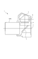
- FIG. 21 shows a schematic cross-sectional view of a digital single-lens reflex camera 1 (hereinafter simply referred to as a camera) as an optical apparatus including the above-described variable magnification optical system ZL.
- a camera digital single-lens reflex camera 1
- this camera 1 light from an object (subject) (not shown) is collected by the taking lens 2 (variable magnification optical system ZL) and imaged on the focusing screen 4 via the quick return mirror 3.
- the light imaged on the focusing screen 4 is reflected a plurality of times in the pentaprism 5 and guided to the eyepiece lens 6.
- the photographer can observe the object (subject) image as an erect image through the eyepiece 6.
- the camera 1 shown in FIG. 21 may hold the variable magnification optical system ZL in a removable manner, or may be formed integrally with the variable magnification optical system ZL.
- the camera 1 may be a so-called single-lens reflex camera or a compact camera without a quick return mirror or the like.
- variable magnification optical system ZL having a four-group configuration is shown.
- the above-described configuration conditions and the like can be applied to other group configurations such as the fifth group and the sixth group. It is. Further, the 3a lens group G3a and the 3b lens group G3b of the third lens group G3 can be moved separately during zooming.
- a focusing lens group that performs focusing from an object at infinity to a near object by moving a single lens group, a plurality of lens groups, or a partial lens group in the optical axis direction may be used.
- the focusing lens group can be applied to autofocus, and is also suitable for driving a motor for autofocus (such as an ultrasonic motor).
- the second lens group G2 is preferably a focusing lens group.
- the lens surface may be an aspherical surface.
- any one of an aspheric surface by grinding, a glass mold aspheric surface in which glass is formed into an aspheric shape by a mold, and a composite aspheric surface in which resin is formed in an aspheric shape on the surface of the glass may be used.
- the lens surface may be a diffractive surface, and the lens may be a gradient index lens (GRIN lens) or a plastic lens.
- GRIN lens gradient index lens
- the aperture stop S is preferably arranged on the most object side in the vicinity of the third lens group G3 or between the second lens group G2 and the third lens group G3, but without providing a member as an aperture stop.
- the role may be substituted by a lens frame.
- an antireflection film having a high transmittance in a wide wavelength range is applied to each lens surface, thereby reducing flare and ghost and achieving high optical performance with high contrast.
- the zoom optical system ZL of this embodiment has a focal length in terms of 35 mm film size of about 25 to 29 mm at the wide-angle end state, about 150 to 170 mm at the telephoto end state, and a zoom ratio of about 5 to 6. It is.
- the first lens group G1 has two positive lens components and one negative lens component.
- the first lens group G1 it is preferable to dispose the lens components in order of negative positive / positive in order from the object side. Also, it is preferable to bond the first and second lens components together.
- the second lens group G2 has one positive lens component and three negative lens components. In the second lens group G2, it is preferable to dispose lens components in order of negative, negative, positive and negative in order from the object side.
- the 3a lens group G3a has two positive lens components and one negative lens component.
- the third-a lens group G3a it is preferable to dispose lens components in order of positive / negative from the object side.
- the order of the lens components may be negative / positive / positive / positive / negative.
- the third lens group G3b has one positive lens component and one negative lens component.
- the arrangement of the lens components in the third lens group G3b may be negative or positive or negative in order from the object side, but they are preferably bonded and held by one lens holding portion.
- variable magnification optical system ZL of the present embodiment it is preferable that the fourth lens group G4 can be changed in lens configuration in accordance with aberration correction at the time of image stabilization.
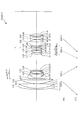
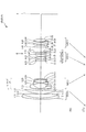
- FIG. 1 is a cross-sectional view showing the configuration of the variable magnification optical system ZL according to the present embodiment.
- the state of movement of each lens group in the change of the distance state is indicated by an arrow below FIG.
- the variable magnification optical system ZL according to the present embodiment has a first lens group G1 having a positive refractive power and a negative refractive power in order from the object side along the optical axis.
- the lens unit includes a second lens group G2, a third lens group G3 having a positive refractive power, and a fourth lens group G4 having a positive refractive power.
- the lens position changes from the wide-angle end state to the telephoto end state, the air gap between the first lens group G1 and the second lens group G2 increases, and the air between the second lens group G2 and the third lens group G3.
- the first lens group G1, the third lens group G3, and the fourth lens group G4 move in the object direction so that the distance decreases and the air distance between the third lens group G3 and the fourth lens group G4 decreases.
- the second lens group moves to the image plane side.
- the third lens group G3 includes, in order from the object side, a third lens group G3a having a positive refractive power and a third lens group G3b having a negative refractive power.
- the third lens group G3b is an optical axis. By moving in the orthogonal direction, camera shake correction (anti-vibration) is performed.
- the aperture stop S is located between the second lens group G2 and the third lens group G3, and moves together with the 3a lens group G3a when zooming from the wide-angle end state to the telephoto end state.
- the flare cut stop FS is located between the third lens group G3 and the fourth lens group G4, and does not move during image stabilization, but moves with the third lens group G3 during zooming. Focusing from a long distance to a short distance is performed by moving the second lens group G2 in the object direction.
- the height of the aspheric surface in the direction perpendicular to the optical axis is y, and the distance (sag amount) along the optical axis from the tangential plane of the apex of each aspheric surface to each aspheric surface at height y.
- Is S (y) r is the radius of curvature of the reference sphere (paraxial radius of curvature)
- ⁇ is the conic constant
- An is the nth-order aspheric coefficient, and is expressed by the following equation (a). .
- “E ⁇ n” represents “ ⁇ 10 ⁇ n ”.
- the secondary aspheric coefficient A2 is zero.
- an aspherical surface is marked with * on the left side of the surface number.
- FIG. 1 is a diagram showing a configuration of a variable magnification optical system ZL1 according to the first example.
- the first lens group G1 includes, in order from the object side, a cemented lens of a negative meniscus lens L11 having a convex surface facing the object side and a biconvex positive lens L12, and an object It comprises a positive meniscus lens L13 having a convex surface on the side.
- the second lens group G2 in order from the object side, includes a negative meniscus lens L21 having a convex surface directed toward the object side, a biconcave negative lens L22, a biconvex positive lens L23, and a negative surface having a concave surface directed toward the object side.
- the negative meniscus lens L21 including the meniscus lens L24 and positioned closest to the object side of the second lens group G2 is an aspherical lens in which an aspherical surface is formed by providing a resin layer on the glass lens surface on the object side.
- the third lens group G3a of the third lens group G3 includes, in order from the object side, a biconvex positive lens L31, and a biconvex positive lens L32 and a negative meniscus lens L33 having a concave surface facing the object side. Consists of lenses.
- the third lens group G3b of the third lens group G3 includes, in order from the object side, a cemented lens of a biconcave negative lens L34 and a positive meniscus lens L35 having a convex surface facing the object side.
- the biconcave negative lens L34 located closest to the object side of G3b is an aspheric lens in which an aspheric surface is formed by providing a resin layer on the glass lens surface on the object side.
- the fourth lens group G4 includes, in order from the object, a biconvex positive lens L41, a cemented lens of a biconvex positive lens L42 and a biconcave negative lens L43, and a biconvex positive lens L44.
- the biconvex positive lens L41 that is configured and is located closest to the object side in the fourth lens group G4 is an aspheric lens having an aspheric lens surface on the object side.
- the focal length of the entire system is f
- the image stabilization correction coefficient ratio of the amount of image movement on the imaging surface to the amount of movement of the moving lens group in shake correction
- the moving lens group for blur correction may be moved in the direction orthogonal to the optical axis by (f ⁇ tan ⁇ ) / K (this description is the same in the following embodiments).
- the image stabilization correction coefficient is 0.999
- the focal length is 18.50 (mm). Therefore, the 3b lens for correcting the rotation blur of 0.60 ° is used.
- the movement amount of the group G3b is 0.194 (mm).
- the image stabilization correction coefficient is 1.789 and the focal length is 131.00 (mm). Therefore, the first correction for correcting the rotation blur of 0.27 ° is performed.
- the moving amount of the 3b lens group G3b is 0.345 (mm).
- f represents the focal length
- FNO represents the F number
- 2 ⁇ represents the angle of view (unit is “°”)
- Bf represents the back focus.
- the surface number is the order of the lens surfaces from the object side along the direction of travel of the light beam
- the surface interval is the distance on the optical axis from each optical surface to the next optical surface
- “mm” is generally used for the focal length f, the radius of curvature, the surface interval, and other length units listed in all the following specifications, but the optical system is proportionally enlarged or reduced.
- the curvature radius ⁇ indicates a plane, and the refractive index of air 1.000 is omitted.
- the description of these symbols and the description of the specification table are the same in the following embodiments.
- the lens surfaces of the sixth surface, the twenty-first surface, and the twenty-sixth surface are formed in an aspherical shape.
- Table 2 below shows aspheric data, that is, the values of the conic constant ⁇ and the aspheric constants A4 to A10.
- the on-axis air gap d25 and the back focus Bf between the first lens group G4 and the fourth lens group G4 change during zooming.
- Table 3 below shows variable intervals at the respective focal lengths in the wide-angle end state, the intermediate focal length state, and the telephoto end state.
- Table 4 below shows values corresponding to the conditional expressions in the first embodiment.
- Lw is the total length in the wide-angle end state
- fw is the focal length of the entire system in the wide-angle end state
- ft is the focal length of the entire system in the telephoto end state
- ⁇ d1 is from the wide-angle end state to the telephoto end state.
- the movement distance on the optical axis of the first lens group G1 when the lens position state changes until ⁇ d3 is on the optical axis of the third lens group G3 when the lens position state changes from the wide-angle end state to the telephoto end state.
- F1 is the focal length of the first lens group G1
- f3 is the focal length of the third lens group G3
- f4 is the focal length of the fourth lens group G4
- Bfw is the back focus in the wide-angle end state.
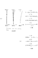
- FIG. 2A shows an aberration diagram in the infinite focus state in the wide-angle end state of the first embodiment
- FIG. 3 shows an aberration diagram in the infinite focus state in the intermediate focal length state
- FIG. FIG. 4A shows an aberration diagram in the infinitely focused state
- FIG. 2B shows a coma aberration diagram when the blur correction is performed with respect to the rotation blur of 0.60 ° in the infinity photographing state at the wide-angle end state of the first embodiment
- the telephoto of the first embodiment is shown in FIG.
- FIG. 4B shows a coma aberration diagram when blur correction is performed with respect to 0.27 ° rotational blur in the infinity photographing state in the end state.
- FNO is an F number
- A is a half angle of view (unit “°”)
- the spherical aberration diagram shows the F-number value corresponding to the maximum aperture
- the astigmatism diagram and the distortion diagram show the maximum value of the field angle
- the coma diagram shows the value of each field angle.
- the solid line indicates the sagittal image plane
- the broken line indicates the meridional image plane.
- the solid line indicates the spherical aberration.
- this aberration diagram is the same in the following examples. As is apparent from the respective aberration diagrams, in the first embodiment, it is understood that various aberrations are well corrected in each focal length state from the wide-angle end state to the telephoto end state, and excellent imaging performance is obtained.
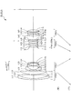
- FIG. 5 is a diagram showing a configuration of the variable magnification optical system ZL2 according to the second example.
- the first lens group G1 includes, in order from the object side, a cemented lens of a negative meniscus lens L11 having a convex surface facing the object side and a biconvex positive lens L12, and an object It comprises a positive meniscus lens L13 having a convex surface on the side.
- the second lens group G2 in order from the object side, includes a negative meniscus lens L21 having a convex surface directed toward the object side, a biconcave negative lens L22, a biconvex positive lens L23, and a negative surface having a concave surface directed toward the object side.
- the negative meniscus lens L21 including the meniscus lens L24 and positioned closest to the object side of the second lens group G2 is an aspherical lens in which an aspherical surface is formed by providing a resin layer on the glass lens surface on the object side.
- the third lens group G3a of the third lens group G3 includes, in order from the object side, a biconvex positive lens L31, and a cemented lens of a biconvex positive lens L32 and a biconcave negative lens L33.
- the third lens group G3b of the third lens group G3 includes, in order from the object side, a cemented lens of a biconcave negative lens L34 and a positive meniscus lens L35 having a convex surface facing the object side.
- the biconcave negative lens L34 located closest to the object side is an aspherical lens in which an aspherical surface is formed by providing a resin layer on the glass lens surface on the object side.
- the fourth lens group G4 includes, in order from the object, a biconvex positive lens L41, a cemented lens of a biconvex positive lens L42 and a biconcave negative lens L43, and a biconvex positive lens L44.
- the biconvex positive lens L41 that is configured and is located closest to the object side in the fourth lens group G4 is an aspheric lens having an aspheric lens surface on the object side.
- the image stabilization correction coefficient is 0.928, and the focal length is 18.50 (mm). Therefore, the second correction for correcting the rotation blur of 0.60 ° is performed.
- the moving amount of the 3b lens group G3b is 0.209 (mm).
- the image stabilization correction coefficient is 1.687, and the focal length is 131.00 (mm). Therefore, the second correction for correcting the rotational blur of 0.27 ° is performed.
- the moving amount of the 3b lens group G3b is 0.369 (mm).
- the sixth, twenty-first, and twenty-sixth lens surfaces are formed in an aspherical shape.
- Table 6 below shows the aspheric data, that is, the values of the conic constant ⁇ and the aspheric constants A4 to A10.
- the on-axis air gap d25 and the back focus Bf between the first lens group G4 and the fourth lens group G4 change during zooming.
- Table 7 below shows variable intervals at the respective focal lengths in the wide-angle end state, the intermediate focal length state, and the telephoto end state.
- Table 8 shows values corresponding to the conditional expressions in the second embodiment.
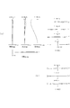
- FIG. 6A is an aberration diagram in the infinite focus state in the wide-angle end state of FIG. 6A
- FIG. 7 is an aberration diagram in the infinite focus state in the intermediate focal length state
- FIG. FIG. 8A shows an aberration diagram of the in-focus state at infinity
- FIG. 6B shows a coma aberration diagram when the shake correction is performed with respect to the rotational shake of 0.60 ° in the infinity photographing state at the wide-angle end state of the second embodiment, and the telephoto of the second embodiment.
- FIG. 8B shows a coma aberration diagram when blur correction is performed with respect to 0.27 ° rotational blur in the infinity shooting state in the end state.
- various aberrations are favorably corrected in each focal length state from the wide-angle end state to the telephoto end state, and excellent imaging performance is obtained.
- FIG. 9 is a diagram illustrating a configuration of the variable magnification optical system ZL3 according to the third example.
- the first lens group G1 includes, in order from the object side, a cemented lens of a negative meniscus lens L11 having a convex surface facing the object side and a biconvex positive lens L12, and an object It comprises a positive meniscus lens L13 having a convex surface on the side.
- the second lens group G2 in order from the object side, includes a negative meniscus lens L21 having a convex surface directed toward the object side, a biconcave negative lens L22, a biconvex positive lens L23, and a negative surface having a concave surface directed toward the object side.
- the negative meniscus lens L21 including the meniscus lens L24 and positioned closest to the object side of the second lens group G2 is an aspherical lens in which an aspherical surface is formed by providing a resin layer on the glass lens surface on the object side.
- the third lens group G3a of the third lens group G3 includes, in order from the object side, a biconvex positive lens L31, and a biconvex positive lens L32 and a negative meniscus lens L33 having a concave surface facing the object side. Consists of lenses.
- the third lens group G3b of the third lens group G3 includes, in order from the object side, a cemented lens of a biconcave negative lens L34 and a positive meniscus lens L35 having a convex surface facing the object side.
- the biconcave negative lens L34 located closest to the object side is an aspherical lens in which an aspherical surface is formed by providing a resin layer on the glass lens surface on the object side.
- the fourth lens group G4 has, in order from the object side, a biconvex positive lens L41, a cemented lens of a biconvex positive lens L42 and a biconcave negative lens L43, and a convex surface directed toward the image side.
- the biconvex positive lens L41 which includes the positive meniscus lens L44 and is located closest to the object side in the fourth lens group G4, is an aspheric lens having an aspheric lens surface on the object side.
- the image stabilization correction coefficient is 1.000 and the focal length is 18.50 (mm), so the third b for correcting the rotation blur of 0.60 °.
- the moving amount of the lens group G3b is 0.194 (mm).
- the image stabilization correction coefficient is 1.797 and the focal length is 105.00 (mm), so that the rotation blur of 0.30 ° is corrected.
- the moving amount of the third lens group G3b is 0.306 (mm).
- the sixth, twenty-first, and twenty-sixth lens surfaces are formed in an aspherical shape.
- Table 10 below shows the aspheric data, that is, the values of the conic constant ⁇ and the aspheric constants A4 to A10.
- the on-axis air gap d25 and the back focus Bf between the first lens group G4 and the fourth lens group G4 change during zooming.
- Table 11 below shows variable intervals at the respective focal lengths in the wide-angle end state, the intermediate focal length state, and the telephoto end state.
- Table 12 shows values corresponding to the conditional expressions in the third embodiment.
- FIG. 10A shows an aberration diagram in the infinite focus state in the wide-angle end state of this third embodiment
- FIG. 11 shows an aberration diagram in the infinite focus state in the intermediate focal length state
- FIG. FIG. 12A shows an aberration diagram in the infinitely focused state
- FIG. 10B shows a coma aberration diagram when the blur correction is performed with respect to the rotational shake of 0.60 ° in the infinity photographing state at the wide-angle end state of the third example
- FIG. 12B shows a coma aberration diagram when blur correction is performed with respect to a rotational blur of 0.30 ° in the infinity photographing state at the telephoto end state.
- various aberrations are favorably corrected in each focal length state from the wide-angle end state to the telephoto end state, and excellent imaging performance is obtained.
- FIG. 13 is a diagram showing a configuration of the variable magnification optical system ZL4 according to the fourth example.
- the first lens group G1 includes, in order from the object side, a cemented lens of a negative meniscus lens L11 having a convex surface facing the object side and a biconvex positive lens L12, and an object It comprises a positive meniscus lens L13 having a convex surface on the side.
- the second lens group G2 in order from the object side, includes a negative meniscus lens L21 having a convex surface directed toward the object side, a biconcave negative lens L22, a biconvex positive lens L23, and a negative surface having a concave surface directed toward the object side.
- the negative meniscus lens L21 including the meniscus lens L24 and positioned closest to the object side of the second lens group G2 is an aspherical lens in which an aspherical surface is formed by providing a resin layer on the glass lens surface on the object side.
- the third lens group G3a of the third lens group G3 includes, in order from the object side, a biconvex positive lens L31, and a biconvex positive lens L32 and a negative meniscus lens L33 having a concave surface facing the object side. Consists of lenses.
- the third lens group G3b of the third lens group G3 includes, in order from the object side, a cemented lens of a biconcave negative lens L34 and a positive meniscus lens L35 having a convex surface facing the object side.
- the biconcave negative lens L34 located closest to the object side is an aspheric lens in which an aspheric surface is formed by providing a resin layer on the glass lens surface on the object side.
- the fourth lens group G4 has, in order from the object side, a biconvex positive lens L41, a cemented lens of a biconvex positive lens L42 and a biconcave negative lens L43, and a convex surface directed toward the image side.
- the positive meniscus lens L41 which includes the positive meniscus lens L44 and is located closest to the object side of the fourth lens group G4, is an aspheric lens having an aspheric lens surface on the object side.
- the image stabilization correction coefficient in the wide-angle end state, is 1.000 and the focal length is 18.50 (mm). Therefore, the third b for correcting the rotation blur of 0.60 °.
- the moving amount of the lens group G3b is 0.194 (mm).
- the image stabilization correction coefficient in the telephoto end state of the fourth embodiment, is 1.815 and the focal length is 105.00 (mm), so that the rotation blur of 0.30 ° is corrected.
- the amount of movement of the third lens group G3b is 0.303 (mm).
- the lens surfaces of the sixth surface, the twenty-first surface, and the twenty-sixth surface are formed in an aspherical shape.
- Table 14 below shows the aspheric data, that is, the values of the conic constant ⁇ and the aspheric constants A4 to A10.
- the on-axis air gap d25 and the back focus Bf between the first lens group G4 and the fourth lens group G4 change during zooming.
- Table 15 below shows variable intervals at the respective focal lengths in the wide-angle end state, the intermediate focal length state, and the telephoto end state.
- Table 16 shows values corresponding to the conditional expressions in the fourth embodiment.
- FIG. 14A shows an aberration diagram in the infinite focus state in the wide-angle end state of this fourth embodiment
- FIG. 15 shows an aberration diagram in the infinite focus state in the intermediate focal length state
- FIG. FIG. 16A shows an aberration diagram of the infinitely focused state
- FIG. 14B shows a coma aberration diagram when the shake correction is performed with respect to the rotational shake of 0.60 ° in the infinity photographing state at the wide-angle end state of the fourth embodiment
- FIG. 16B shows a coma aberration diagram when blur correction is performed with respect to 0.30 ° rotational blur in the infinity photographing state at the telephoto end state.
- various aberrations are favorably corrected in each focal length state from the wide-angle end state to the telephoto end state, and excellent imaging performance is obtained.
- FIG. 17 is a diagram showing a configuration of a variable magnification optical system ZL5 according to the fifth example.
- the first lens group G1 includes, in order from the object side, a cemented lens of a negative meniscus lens L11 having a convex surface facing the object side and a biconvex positive lens L12, and an object It comprises a positive meniscus lens L13 having a convex surface on the side.
- the second lens group G2 in order from the object side, includes a negative meniscus lens L21 having a convex surface directed toward the object side, a biconcave negative lens L22, a biconvex positive lens L23, and a negative surface having a concave surface directed toward the object side.
- the negative meniscus lens L21 including the meniscus lens L24 and positioned closest to the object side of the second lens group G2 is an aspherical lens in which an aspherical surface is formed by providing a resin layer on the glass lens surface on the object side.
- the third lens group G3a of the third lens group G3 includes, in order from the object side, a biconvex positive lens L31, and a cemented lens of a biconvex positive lens L32 and a biconcave negative lens L33.
- the third lens group G3b of the third lens group G3 includes, in order from the object side, a cemented lens of a biconcave negative lens L34 and a positive meniscus lens L35 having a convex surface facing the object side.
- the biconcave negative lens L34 located closest to the object side is an aspheric lens in which an aspheric surface is formed by providing a resin layer on the glass lens surface on the object side.
- the fourth lens group G4 includes, in order from the object side, a biconvex positive lens L41, a cemented lens of a positive meniscus lens L42 having a convex surface facing the image surface and a biconcave negative lens L43, and a biconvex shape.
- the biconvex positive lens L41 which is composed of the positive lens L44 and is located closest to the object side of the fourth lens group G4, is an aspheric lens having an aspheric lens surface on the object side.
- the image stabilization correction coefficient in the wide-angle end state, is 0.999 and the focal length is 18.50 (mm), so the third b for correcting the rotation blur of 0.60 °.
- the moving amount of the lens group G3b is 0.194 (mm).
- the image stabilization correction coefficient in the telephoto end state of the fifth embodiment, is 1.803 and the focal length is 131.00 (mm).
- the amount of movement of the third lens group G3b is 0.342 (mm).
- the sixth, twenty-first, and twenty-sixth lens surfaces are formed in an aspherical shape.
- Table 18 below shows aspheric data, that is, the values of the conic constant ⁇ and the aspheric constants A4 to A10.
- the on-axis air gap d25 and the back focus Bf between the first lens group G4 and the fourth lens group G4 change during zooming.
- Table 19 below shows variable intervals at each focal length in the wide-angle end state, the intermediate focal length state, and the telephoto end state.
- Table 20 shows values corresponding to the conditional expressions in the fifth embodiment.
- FIG. 18A shows an aberration diagram in the infinite focus state in the wide-angle end state of this fifth embodiment
- FIG. 19 shows an aberration diagram in the infinite focus state in the intermediate focal length state
- FIG. FIG. 20A shows an aberration diagram of the infinitely focused state
- FIG. 18B shows a coma aberration diagram when the blur correction is performed with respect to the rotational blur of 0.60 ° in the infinity photographing state at the wide-angle end state of the fifth example
- FIG. 20B shows a coma aberration diagram when blur correction is performed for 0.27 ° rotational blur in the infinity shooting state at the telephoto end state.
- FIG. 22 is a diagram showing a configuration of the variable magnification optical system ZL6 according to the sixth example.
- the first lens group G1 includes, in order from the object side, a cemented lens of a negative meniscus lens L11 having a convex surface facing the object side and a biconvex lens L12, and a convex surface facing the object side. And a positive meniscus lens L13.
- the second lens group G2 includes, in order from the object side, a negative meniscus lens L21 having a convex surface directed toward the object side, a biconcave lens L22, a biconvex lens L23, and a negative meniscus lens L24 having a concave surface directed toward the object side.
- the negative meniscus lens L21 located closest to the object side in the two-lens group G2 is an aspherical lens in which an aspherical surface is formed by providing a resin layer on the glass lens surface on the object side.
- the third lens group G3a of the third lens group G3 includes, in order from the object side, a biconvex lens L31, and a cemented lens of the biconvex lens L32 and a negative meniscus lens L33 having a concave surface facing the object side.
- the third lens group G3b of the third lens group G3 is composed of, in order from the object side, a cemented lens of a biconcave lens L34 and a positive meniscus lens L35 having a convex surface facing the object side.
- the biconcave lens L34 located on the side is an aspheric lens in which a resin layer is provided on the glass lens surface on the object side to form an aspheric surface.
- the fourth lens group G4 includes, in order from the object side, a biconvex lens L41, a cemented lens of the biconvex lens L42 and the biconcave lens L43, and a positive meniscus lens L44 having a convex surface directed to the image surface side.
- the biconvex lens L41 located closest to the object side of G4 is an aspheric lens having an aspheric lens surface on the object side.
- the focal length of the entire system is f
- the image stabilization correction coefficient ratio of the amount of image movement on the imaging surface to the amount of movement of the moving lens group in shake correction
- the moving lens group for blur correction may be moved in the direction orthogonal to the optical axis by (f ⁇ tan ⁇ ) / K (this description is the same in the following embodiments).
- the image stabilization correction coefficient is 0.999
- the focal length is 18.50 (mm). Therefore, the 3b lens for correcting the rotation blur of 0.60 ° is used.
- the movement amount of the group G3b is 0.194 (mm).
- the image stabilization correction coefficient is 1.466 and the focal length is 105.00 (mm). Therefore, the first correction for correcting the rotation blur of 0.30 ° is performed.
- the moving amount of the 3b lens group G3b is 0.250 (mm).
- Table 21 below provides values of specifications of the sixth example.
- f represents the focal length
- FNO represents the F number
- 2 ⁇ represents the angle of view (unit is “°”)
- Bf represents the back focus.
- F1 is the focal length of the first lens group G1
- f2 is the focal length of the second lens group G2
- f3 is the focal length of the third lens group G3
- f4 is the focal length of the fourth lens group G4
- ⁇ d1 is the first focal length.
- the moving distance of the lens group G1 is shown respectively.
- the surface number is the order of the lens surfaces from the object side along the direction of travel of the light beam
- the surface interval is the distance on the optical axis from each optical surface to the next optical surface
- mm is generally used for the focal length f, the radius of curvature, the surface interval, and other length units listed in all the following specifications, but the optical system is proportionally enlarged or reduced. However, since the same optical performance can be obtained, it is not limited to this.
- the curvature radius ⁇ indicates a plane, and the refractive index of air 1.000 is omitted. The description of these symbols and the description of the specification table are the same in the following embodiments.
- the sixth, twenty-first, and twenty-sixth lens surfaces are formed in an aspherical shape.
- Table 22 below shows aspheric data, that is, the values of the conic constant ⁇ and the aspheric constants A4 to A10.
- the on-axis air gap d25 and the back focus Bf between the first lens group G4 and the fourth lens group G4 change during zooming.
- Table 23 below shows variable intervals at the respective focal lengths in the wide-angle end state, the intermediate focal length state, and the telephoto end state.
- Table 24 below shows values corresponding to the conditional expressions in the sixth embodiment.
- Lw is the total length in the wide-angle end state
- fw is the focal length of the entire system in the wide-angle end state
- ⁇ d1 is the first lens group when the lens position changes from the wide-angle end state to the telephoto end state.
- G1 is the movement distance on the optical axis
- ft is the focal length of the entire system in the telephoto end state
- f1 is the focal length of the first lens group G1
- f3 is the focal length of the third lens group G3
- f4 is the first focal length.
- the focal length of the four lens group G4, and Bfw respectively represent the back focus in the wide-angle end state. The description of this symbol is the same in the following embodiments.
- FIG. 23A shows an aberration diagram in the infinite focus state in the wide-angle end state of the sixth embodiment
- FIG. 24 shows an aberration diagram in the infinite focus state in the intermediate focal length state
- FIG. 24 shows the aberration diagram in the telephoto end state.
- FIG. 25A shows an aberration diagram in the infinitely focused state.
- FIG. 23B shows a coma aberration diagram when the shake correction is performed for the rotational shake of 0.60 ° in the infinity photographing state at the wide-angle end state of the sixth embodiment, and the telephoto of the sixth embodiment.
- FIG. 25B shows a coma aberration diagram when blur correction is performed with respect to a rotational blur of 0.30 ° in the infinity shooting state in the end state.
- FNO is an F number
- A is a half angle of view (unit “°”)
- the spherical aberration diagram shows the F-number value corresponding to the maximum aperture
- the astigmatism diagram and the distortion diagram show the maximum value of the field angle
- the coma diagram shows the value of each field angle.
- the solid line indicates the sagittal image plane
- the broken line indicates the meridional image plane.
- the solid line indicates the spherical aberration.
- this aberration diagram is the same in the following examples. As is apparent from each aberration diagram, in the sixth example, it is understood that various aberrations are well corrected in each focal length state from the wide-angle end state to the telephoto end state, and excellent imaging performance is obtained.
Landscapes
- Physics & Mathematics (AREA)
- General Physics & Mathematics (AREA)
- Optics & Photonics (AREA)
- Lenses (AREA)
Abstract
Description
0.25 < (Lw・fw)/(Δd1・ft) < 0.55
2.20 < f3/fw < 4.50
の条件を満足するように構成される。
0.42<(Lw・fw)/(Δd3・ft) < 0.90
の条件を満足してもよい。
3.50 < f1/fw < 8.00
の条件を満足してもよい。
0.30 < f3/ft < 1.00
の条件を満足してもよい。
0.80 < f3/f4 < 1.60
1.90 < Bfw/fw < 3.00
の条件を満足してもよい。
0.15 < (Lw・fw)/(Δd1・ft) < 0.58
0.42 < (Lw・fw)/(Δd3・ft) < 0.90
2.20 < f3/fw < 4.50
の条件を満足するように構成される。
0.25 < (Lw・fw)/(Δd1・ft) < 0.55
2.20 < f3/fw < 4.50
の条件を満足する。
0.42 < (Lw・fw)/(Δd3・ft) < 0.90 (2)
2.20 < f3/fw < 4.50 (3)
1.90 < Bfw/fw < 3.00 (7)
+A4×y4+A6×y6+A8×y8+A10×y10 (a)
図1は、第1実施例に係る変倍光学系ZL1の構成を示す図である。この図1の変倍光学系ZL1において、第1レンズ群G1は、物体側から順に、物体側に凸面を向けた負メニスカスレンズL11と両凸形状の正レンズL12との接合レンズ、及び、物体側に凸面を向けた正メニスカスレンズL13から構成される。第2レンズ群G2は、物体側から順に、物体側に凸面を向けた負メニスカスレンズL21、両凹形状の負レンズL22、両凸形状の正レンズL23、及び、物体側に凹面を向けた負メニスカスレンズL24から構成され、第2レンズ群G2の最も物体側に位置する負メニスカスレンズL21は、物体側のガラスレンズ面に樹脂層を設けて非球面を形成した非球面レンズである。第3レンズ群G3の第3aレンズ群G3aは、物体側から順に、両凸形状の正レンズL31、及び、両凸形状の正レンズL32と物体側に凹面を向けた負メニスカスレンズL33との接合レンズから構成される。第3レンズ群G3の第3bレンズ群G3bは、物体側から順に、両凹形状の負レンズL34と物体側に凸面を向けた正メニスカスレンズL35との接合レンズから構成され、この第3bレンズ群G3bの最も物体側に位置する両凹形状の負レンズL34は、物体側のガラスレンズ面に樹脂層を設けて非球面を形成した非球面レンズである。第4レンズ群G4は、物体側から順に、両凸形状の正レンズL41、両凸形状の正レンズL42と両凹形状の負レンズL43との接合レンズ、及び、両凸形状の正レンズL44から構成され、第4レンズ群G4の最も物体側に位置する両凸形状の正レンズL41は、物体側のレンズ面を非球面形状とした非球面レンズである。
も同様である。
広角端 中間焦点距離 望遠端
f = 18.50 ~ 70.00 ~ 131.00
FNO = 3.39 ~ 4.66 ~ 5.55
2ω = 77.88 ~ 22.29 ~ 12.14
像高 = 14.20 ~ 14.20 ~ 14.20
全長 =131.568 ~ 170.966 ~ 191.247
面番号 曲率半径 面間隔 アッヘ゛数 屈折率
1 132.7091 2.0000 23.78 1.846660
2 69.0393 7.6047 70.23 1.487490
3 -613.4510 0.1000
4 58.5782 6.0340 50.88 1.658441
5 211.3695 (d5)
*6 277.8767 0.1500 38.09 1.553890
7 133.7106 1.2000 46.63 1.816000
8 14.4529 6.6840
9 -36.6145 1.0000 46.63 1.816000
10 55.0282 0.1000
11 35.0000 3.9063 23.78 1.846660
12 -37.5947 1.0681
13 -22.3441 1.0000 47.38 1.788000
14 -56.4883 (d14)
15 ∞ 0.5000 (開口絞りS)
16 38.9611 2.7439 64.19 1.516798
17 -45.5432 0.1000
18 24.9617 3.4225 81.61 1.497000
19 -36.3323 1.0000 32.35 1.850260
20 -313.2423 3.0000
*21 -34.6816 0.1000 38.09 1.553890
22 -35.1754 1.0000 64.10 1.516800
23 36.6948 1.5591 27.51 1.755199
24 52.5702 1.5000
25 ∞ (d25) (フレアカット絞り)
*26 55.8550 3.9010 64.03 1.516120
27 -27.9232 0.5000
28 500.0000 3.3875 60.67 1.563839
29 -26.2504 1.3000 37.16 1.834000
30 46.2587 0.8872
31 110.0000 3.2902 50.89 1.658441
32 -38.6328 (Bf)
[レンス゛群焦点距離及び移動距離]
f1= 98.396
f2=-14.860
f3= 47.189
f4= 43.127
Δd1= 59.697
Δd3= 36.679
κ A4 A6 A8 A10
第6面 1.0000 1.67350E-05 -3.76300E-08 8.64890E-11 -4.98470E-14
第21面 5.9254 2.86560E-05 5.91680E-09 4.57110E-10 0.00000E+00
第26面 -26.7202 -1.22480E-05 -2.80120E-08 -1.97490E-11 0.00000E+00
広角端 中間焦点距離 望遠端
f 18.500 70.000 131.000
d5 2.070 38.567 49.422
d14 26.242 8.138 1.800
d25 6.250 2.232 1.450
Bf 37.967 62.990 79.536
(1)(Lw・fw)/(Δd1・ft)=0.311
(2)(Lw・fw)/(Δd3・ft)=0.505
(3)f3/fw=2.551
(4)f1/fw=5.319
(5)f3/ft=0.360
(6)f3/f4=1.094
(7)Bfw/fw=2.052
図5は、第2実施例に係る変倍光学系ZL2の構成を示す図である。この図5の変倍光学系ZL2において、第1レンズ群G1は、物体側から順に、物体側に凸面を向けた負メニスカスレンズL11と両凸形状の正レンズL12との接合レンズ、及び、物体側に凸面を向けた正メニスカスレンズL13から構成される。第2レンズ群G2は、物体側から順に、物体側に凸面を向けた負メニスカスレンズL21、両凹形状の負レンズL22、両凸形状の正レンズL23、及び、物体側に凹面を向けた負メニスカスレンズL24から構成され、第2レンズ群G2の最も物体側に位置する負メニスカスレンズL21は、物体側のガラスレンズ面に樹脂層を設けて非球面を形成した非球面レンズである。第3レンズ群G3の第3aレンズ群G3aは、物体側から順に、両凸形状の正レンズL31、及び、両凸形状の正レンズL32と両凹形状の負レンズL33との接合レンズから構成される。第3レンズ群G3の第3bレンズ群G3bは、物体側から順に、両凹形状の負レンズL34と物体側に凸面を向けた正メニスカスレンズL35との接合レンズから構成され、第3bレンズ群G3bの最も物体側に位置する両凹形状の負レンズL34は物体側のガラスレンズ面に樹脂層を設けて非球面を形成した非球面レンズである。第4レンズ群G4は、物体側から順に、両凸形状の正レンズL41、両凸形状の正レンズL42と両凹形状の負レンズL43との接合レンズ、及び、両凸形状の正レンズL44から構成され、第4レンズ群G4の最も物体側に位置する両凸形状の正レンズL41は、物体側のレンズ面を非球面形状とした非球面レンズである。
広角端 中間焦点距離 望遠端
f = 18.50 ~ 70.00 ~ 131.00
FNO = 3.47 ~ 5.11 ~ 5.73
2ω = 76.67 ~ 22.38 ~ 12.14
像高 = 14.20 ~ 14.20 ~ 14.20
全長 =131.591 ~ 170.738 ~ 191.244
面番号 曲率半径 面間隔 アッヘ゛数 屈折率
1 127.1007 2.0000 23.78 1.846660
2 68.0866 7.4621 70.23 1.487490
3 -789.7221 0.1000
4 58.5100 5.7779 50.88 1.658441
5 205.2524 (d5)
*6 155.8421 0.1500 38.09 1.553890
7 91.9644 1.2000 42.72 1.834807
8 14.4078 6.8486
9 -33.7631 1.0000 46.63 1.816000
10 52.3310 0.1000
11 35.0000 4.0788 23.78 1.846660
12 -35.3134 1.1463
13 -20.8608 1.0000 47.38 1.788000
14 -46.1994 (d14)
15 ∞ 0.5000 (開口絞りS)
16 33.3603 2.9346 64.19 1.516798
17 -42.6922 0.1000
18 24.9127 3.3760 81.61 1.497000
19 -38.2884 1.0000 32.35 1.850260
20 573.0840 3.0000
*21 -37.4522 0.1000 38.09 1.553890
22 -37.6846 1.0000 64.10 1.516800
23 31.2120 1.6802 27.51 1.755199
24 50.0206 1.5000
25 ∞ (d25) (フレアカット絞り)
*26 64.5178 3.2899 64.03 1.516120
27 -35.6588 0.5000
28 500.0000 2.0396 70.41 1.487490
29 -78.8097 1.3000 32.35 1.850260
30 50.8610 0.8683
31 140.0573 3.6434 70.41 1.487490
32 -29.2586 (Bf)
[レンズ群焦点距離及び移動距離]
f1= 98.935
f2=-15.109
f3= 44.583
f4= 46.104
Δd1= 59.653
Δd3= 38.373
κ A4 A6 A8 A10
第6面 1.0000 1.80020E-05 -3.75590E-08 6.82670E-11 8.79960E-14
第21面 9.7304 3.14860E-05 5.10490E-08 8.64750E-10 0.00000E+00
第26面 -0.2727 -3.48330E-05 2.53290E-08 -1.86100E-10 0.00000E+00
広角端 中間焦点距離 望遠端
f 18.500 70.000 131.000
d5 2.070 33.852 48.965
d14 27.416 7.230 1.800
d25 6.418 2.049 1.450
Bf 37.991 69.912 81.333
(1)(Lw・fw)/(Δd1・ft)=0.312
(2)(Lw・fw)/(Δd3・ft)=0.484
(3)f3/fw=2.410
(4)f1/fw=5.348
(5)f3/ft=0.340
(6)f3/f4=0.967
(7)Bfw/fw=2.054
図9は、第3実施例に係る変倍光学系ZL3の構成を示す図である。この図9の変倍光学系ZL3において、第1レンズ群G1は、物体側から順に、物体側に凸面を向けた負メニスカスレンズL11と両凸形状の正レンズL12との接合レンズ、及び、物体側に凸面を向けた正メニスカスレンズL13から構成される。第2レンズ群G2は、物体側から順に、物体側に凸面を向けた負メニスカスレンズL21、両凹形状の負レンズL22、両凸形状の正レンズL23、及び、物体側に凹面を向けた負メニスカスレンズL24から構成され、第2レンズ群G2の最も物体側に位置する負メニスカスレンズL21は、物体側のガラスレンズ面に樹脂層を設けて非球面を形成した非球面レンズである。第3レンズ群G3の第3aレンズ群G3aは、物体側から順に、両凸形状の正レンズL31、及び、両凸形状の正レンズL32と物体側に凹面を向けた負メニスカスレンズL33との接合レンズから構成される。第3レンズ群G3の第3bレンズ群G3bは、物体側から順に、両凹形状の負レンズL34と物体側に凸面を向けた正メニスカスレンズL35との接合レンズから構成され、第3bレンズ群G3bの最も物体側に位置する両凹形状の負レンズL34は物体側のガラスレンズ面に樹脂層を設けて非球面を形成した非球面レンズである。第4レンズ群G4は、物体側から順に、両凸形状の正レンズL41、両凸形状の正レンズL42と両凹形状の負レンズL43との接合レンズ、及び、像面側に凸面を向けた正メニスカスレンズL44から構成され、第4レンズ群G4の最も物体側に位置する両凸形状の正レンズL41は、物体側のレンズ面を非球面形状とした非球面レンズである。
広角端 中間焦点距離 望遠端
f = 18.50 ~ 65.00 ~ 105.00
FNO = 3.52 ~ 5.13 ~ 5.74
2ω = 78.26 ~ 24.33 ~ 15.24
像高 = 14.20 ~ 14.20 ~ 14.20
全長 =131.517 ~ 163.372 ~ 180.515
面番号 曲率半径 面間隔 アッヘ゛数 屈折率
1 134.7329 2.0000 23.78 1.846660
2 68.5573 6.5591 70.23 1.487490
3 -633.6719 0.1000
4 53.4321 5.1596 50.88 1.658441
5 189.7811 (d5)
*6 182.9094 0.1500 38.09 1.553890
7 103.7413 1.2000 46.57 1.804000
8 14.5151 6.9532
9 -31.1324 1.0000 39.58 1.804398
10 49.3719 0.1000
11 35.0000 4.2243 23.78 1.846660
12 -32.7363 1.0764
13 -20.5005 1.0000 47.38 1.788000
14 -44.0388 (d14)
15 ∞ 0.5000 (開口絞りS)
16 40.8340 2.7262 64.19 1.516798
17 -38.4648 0.1000
18 27.3585 3.2934 81.61 1.497000
19 -32.0272 1.0000 32.35 1.850260
20 -179.9291 3.0000
*21 -35.4208 0.1000 38.09 1.553890
22 -35.7415 1.0000 64.10 1.516800
23 32.9221 1.5617 23.78 1.846660
24 45.6074 1.5000
25 ∞ (d25) (フレアカット絞り)
*26 162.6073 3.2000 64.03 1.516120
27 -34.1598 0.5000
28 90.0000 2.9026 60.67 1.563839
29 -53.8564 1.3000 32.35 1.850260
30 61.1613 1.3249
31 -309.5498 3.6147 70.41 1.487490
32 -25.1830 (Bf)
[レンズ群焦点距離及び移動距離]
f1= 93.094
f2=-15.473
f3= 47.005
f4= 44.335
Δd1= 48.998
Δd3= 37.545
κ A4 A6 A8 A10
第6面 1.0000 1.65830E-05 -3.43150E-08 5.65390E-11 1.12030E-13
第21面 8.3238 3.21570E-05 7.35370E-08 5.56910E-10 0.00000E+00
第26面 19.1791 -3.00450E-05 0.00000E+00 0.00000E+00 0.00000E+00
広角端 中間焦点距離 望遠端
f 18.500 65.000 105.000
d5 2.098 28.005 39.057
d14 27.305 6.199 1.800
d25 6.951 2.079 1.450
Bf 38.017 69.944 81.062
(1)(Lw・fw)/(Δd1・ft)=0.473
(2)(Lw・fw)/(Δd3・ft)=0.617
(3)f3/fw=2.541
(4)f1/fw=5.032
(5)f3/ft=0.448
(6)f3/f4=1.060
(7)Bfw/fw=2.055
図13は、第4実施例に係る変倍光学系ZL4の構成を示す図である。この図13の変倍光学系ZL4において、第1レンズ群G1は、物体側から順に、物体側に凸面を向けた負メニスカスレンズL11と両凸形状の正レンズL12との接合レンズ、及び、物体側に凸面を向けた正メニスカスレンズL13から構成される。第2レンズ群G2は、物体側から順に、物体側に凸面を向けた負メニスカスレンズL21、両凹形状の負レンズL22、両凸形状の正レンズL23、及び、物体側に凹面を向けた負メニスカスレンズL24から構成され、第2レンズ群G2の最も物体側に位置する負メニスカスレンズL21は、物体側のガラスレンズ面に樹脂層を設けて非球面を形成した非球面レンズである。第3レンズ群G3の第3aレンズ群G3aは、物体側から順に、両凸形状の正レンズL31、及び、両凸形状の正レンズL32と物体側に凹面を向けた負メニスカスレンズL33との接合レンズから構成される。第3レンズ群G3の第3bレンズ群G3bは、物体側から順に、両凹形状の負レンズL34と物体側に凸面を向けた正メニスカスレンズL35との接合レンズから構成され、第3bレンズ群G3bの最も物体側に位置する両凹形状の負レンズL34は、物体側のガラスレンズ面に樹脂層を設けて非球面を形成した非球面レンズである。第4レンズ群G4は、物体側から順に、両凸形状の正レンズL41、両凸形状の正レンズL42と両凹形状の負レンズL43との接合レンズ、及び、像面側に凸面を向けた正メニスカスレンズL44から構成され、第4レンズ群G4の最も物体側に位置する正メニスカスレンズL41は、物体側のレンズ面を非球面形状とした非球面レンズである。
広角端 中間焦点距離 望遠端
f = 18.50 ~ 65.00 ~ 105.00
FNO = 3.51 ~ 5.10 ~ 5.79
2ω = 78.26 ~ 24.32 ~ 15.24
像高 = 14.20 ~ 14.20 ~ 14.20
全長 =131.550 ~ 167.168 ~ 186.160
面番号 曲率半径 面間隔 アッヘ゛数 屈折率
1 141.6433 2.0000 23.78 1.846660
2 72.6601 6.3104 70.23 1.487490
3 -931.1892 0.1000
4 56.0747 4.9593 50.88 1.658441
5 191.8276 (d5)
*6 114.9754 0.1500 38.09 1.553890
7 73.7929 1.2000 46.57 1.804000
8 14.5527 7.7748
9 -30.0224 1.0000 39.58 1.804398
10 47.7644 0.1000
11 35.0000 4.2146 23.78 1.846660
12 -32.9530 1.1617
13 -19.9264 1.0000 47.38 1.788000
14 -42.0535 (d14)
15 ∞ 0.5000 (開口絞りS)
16 44.6991 2.7606 64.19 1.516798
17 -34.8394 0.1000
18 28.4488 3.3997 81.61 1.497000
19 -28.2321 1.0000 32.35 1.850260
20 -119.4787 3.0000
*21 -35.4985 0.1000 38.09 1.553890
22 -35.7580 1.0000 64.10 1.516800
23 29.9881 1.6238 23.78 1.846660
24 43.5041 1.5000
25 ∞ (d25) (フレアカット絞り)
*26 232.2663 3.2000 64.03 1.516120
27 -32.1872 0.5000
28 90.0000 2.9876 60.67 1.563839
29 -49.4149 1.3000 32.35 1.850260
30 60.9686 1.3389
31 -285.1808 3.6098 70.40 1.487490
32 -25.0178 (Bf)
[レンズ群焦点距離及び移動距離]
f1= 100.639
f2=-15.490
f3= 45.735
f4= 45.228
Δd1= 54.610
Δd3= 38.792
κ A4 A6 A8 A10
第6面 1.0000 1.52370E-05 -2.25400E-08 5.16300E-12 2.25290E-13
第21面 8.6305 3.26180E-05 6.91300E-08 6.92310E-10 0.00000E+00
第26面 -183.0712 -2.58810E-05 0.00000E+00 0.00000E+00 0.00000E+00
広角端 中間焦点距離 望遠端
f 18.500 65.000 105.000
d5 2.113 31.473 42.677
d14 26.546 6.189 1.800
d25 6.950 2.036 1.450
Bf 38.050 69.578 82.342
(1)(Lw・fw)/(Δd1・ft)=0.424
(2)(Lw・fw)/(Δd3・ft)=0.598
(3)f3/fw=2.472
(4)f1/fw=5.440
(5)f3/ft=0.436
(6)f3/f4=1.011
(7)Bfw/fw=2.057
図17は、第5実施例に係る変倍光学系ZL5の構成を示す図である。この図17の変倍光学系ZL5において、第1レンズ群G1は、物体側から順に、物体側に凸面を向けた負メニスカスレンズL11と両凸形状の正レンズL12との接合レンズ、及び、物体側に凸面を向けた正メニスカスレンズL13から構成される。第2レンズ群G2は、物体側から順に、物体側に凸面を向けた負メニスカスレンズL21、両凹形状の負レンズL22、両凸形状の正レンズL23、及び、物体側に凹面を向けた負メニスカスレンズL24から構成され、第2レンズ群G2の最も物体側に位置する負メニスカスレンズL21は、物体側のガラスレンズ面に樹脂層を設けて非球面を形成した非球面レンズである。第3レンズ群G3の第3aレンズ群G3aは、物体側から順に、両凸形状の正レンズL31、及び、両凸形状の正レンズL32と両凹形状の負レンズL33との接合レンズから構成される。第3レンズ群G3の第3bレンズ群G3bは、物体側から順に、両凹形状の負レンズL34と物体側に凸面を向けた正メニスカスレンズL35との接合レンズから構成され、第3bレンズ群G3bの最も物体側に位置する両凹形状の負レンズL34は、物体側のガラスレンズ面に樹脂層を設けて非球面を形成した非球面レンズである。第4レンズ群G4は、物体側から順に、両凸形状の正レンズL41、像面側に凸面を向けた正メニスカスレンズL42と両凹形状の負レンズL43との接合レンズ、及び、両凸形状の正レンズL44から構成され、第4レンズ群G4の最も物体側に位置する両凸形状の正レンズL41は、物体側のレンズ面を非球面形状とした非球面レンズである。
広角端 中間焦点距離 望遠端
f = 18.50 ~ 70.00 ~ 131.00
FNO = 3.47 ~ 4.83 ~ 5.77
2ω = 78.07 ~ 22.38 ~ 12.19
像高 = 14.20 ~ 14.20 ~ 14.20
全長 =134.867 ~ 175.840 ~ 197.401
面番号 曲率半径 面間隔 アッヘ゛数 屈折率
1 131.8145 2.0000 32.35 1.850260
2 66.7419 7.5709 81.61 1.497000
3 -1267.3183 0.1000
4 60.4311 6.4106 65.47 1.603000
5 271.9391 (d5)
*6 280.2980 0.1500 38.09 1.553890
7 116.0121 1.2000 46.63 1.816000
8 14.8328 6.7543
9 -31.2380 1.0000 46.63 1.816000
10 55.8688 0.1000
11 37.6211 3.7843 23.78 1.846660
12 -42.5664 1.8254
13 -17.8616 1.0000 47.38 1.788000
14 -25.2572 (d14)
15 ∞ 0.5000 (開口絞りS)
16 35.4547 2.5444 65.47 1.603000
17 -49.0607 0.1000
18 27.6369 3.0607 81.61 1.497000
19 -35.3391 1.0000 32.35 1.850260
20 849.7261 3.0000
*21 -39.3954 0.1000 38.09 1.553890
22 -39.5271 1.0000 64.12 1.516800
23 25.0000 1.4590 27.51 1.755200
24 40.3853 1.5000
25 ∞ (d25) (フレアカット絞り)
*26 57.1912 3.3608 70.45 1.487490
27 -26.1998 0.5000
28 -31341.9590 3.4990 70.45 1.487490
29 -19.9000 1.4000 44.79 1.744000
30 48.2777 0.9461
31 141.0745 3.5724 70.45 1.487490
32 -25.6598 (Bf)
[レンズ群焦点距離及び移動距離]
f1= 107.049
f2=-15.981
f3= 47.794
f4= 47.275
Δd1= 62.534
Δd3= 38.119
κ A4 A6 A8 A10
第6面 1.0000 1.98880E-05 -3.90400E-08 8.42890E-11 1.34030E-13
第21面 6.5091 2.30430E-05 -1.51290E-08 5.59780E-10 -2.19660E-12
第26面 -67.0889 1.07570E-05 -3.20900E-07 2.32710E-09 -8.11680E-12
広角端 中間焦点距離 望遠端
f 18.500 69.998 130.995
d5 2.070 41.366 53.610
d14 29.519 9.146 2.394
d25 5.843 1.767 1.000
Bf 37.997 64.123 80.959
(1)(Lw・fw)/(Δd1・ft)=0.305
(2)(Lw・fw)/(Δd3・ft)=0.500
(3)f3/fw=2.583
(4)f1/fw=5.786
(5)f3/ft=0.365
(6)f3/f4=1.011
(7)Bfw/fw=2.054
図22は、第6実施例に係る変倍光学系ZL6の構成を示す図である。この図22の変倍光学系ZL6において、第1レンズ群G1は、物体側から順に、物体側に凸面を向けた負メニスカスレンズL11と両凸レンズL12との接合レンズ、及び、物体側に凸面を向けた正メニスカスレンズL13から構成される。第2レンズ群G2は、物体側から順に、物体側に凸面を向けた負メニスカスレンズL21、両凹レンズL22、両凸レンズL23、及び、物体側に凹面を向けた負メニスカスレンズL24から構成され、第2レンズ群G2の最も物体側に位置する負メニスカスレンズL21は、物体側のガラスレンズ面に樹脂層を設けて非球面を形成した非球面レンズである。第3レンズ群G3の第3aレンズ群G3aは、物体側から順に、両凸レンズL31、及び、両凸レンズL32と物体側に凹面を向けた負メニスカスレンズL33との接合レンズから構成される。第3レンズ群G3の第3bレンズ群G3bは、物体側から順に、両凹レンズL34と物体側に凸面を向けた正メニスカスレンズL35との接合レンズから構成され、この第3bレンズ群G3bの最も物体側に位置する両凹レンズL34は、物体側のガラスレンズ面に樹脂層を設けて非球面を形成した非球面レンズである。第4レンズ群G4は、物体側から順に、両凸レンズL41、両凸レンズL42と両凹レンズL43との接合レンズ、及び、像面側に凸面を向けた正メニスカスレンズL44から構成され、第4レンズ群G4の最も物体側に位置する両凸レンズL41は、物体側のレンズ面を非球面形状とした非球面レンズである。
説明は、以降の実施例においても同様である)。この第6実施例の広角端においては、防振補正係数は0.999であり、焦点距離は18.50(mm)であるので、0.60°の回転ぶれを補正するための第3bレンズ群G3bの移動量は0.194(mm)である。また、この第6実施例の望遠端においては、防振補正係数は1.466であり、焦点距離は105.00(mm)であるので、0.30°の回転ぶれを補正するための第3bレンズ群G3bの移動量は0.250(mm)である。
及び諸元表の説明は以降の実施例においても同様である。
広角端 中間焦点距離 望遠端
f = 18.50 ~ 65.00 ~ 105.00
FNO = 3.50 ~ 5.07 ~ 5.75
2ω = 78.07 ~ 24.23 ~ 15.19
像高 = 14.20 ~ 14.20 ~ 14.20
全長 =131.536 ~ 165.006 ~ 183.226
面番号 曲率半径 面間隔アッヘ゛数 屈折率
1 143.2140 2.0000 23.78 1.846660
2 71.6646 6.4275 70.23 1.487490
3 -618.5043 0.1000
4 53.9791 5.0660 50.88 1.658441
5 181.7249 (d5)
*6 128.7548 0.1500 38.09 1.553890
7 82.3773 1.2000 46.57 1.804000
8 14.3017 7.0936
9 -30.1601 1.0000 39.58 1.804398
10 50.9493 0.1000
11 35.0000 4.1886 23.78 1.846660
12 -33.0990 1.2340
13 -19.8060 1.0000 47.38 1.788000
14 -41.0790 (d14)
15 ∞ 0.5000 (開口絞りS)
16 44.3882 2.7436 64.19 1.516798
17 -35.2063 0.1000
18 28.1737 3.3532 81.61 1.497000
19 -29.1030 1.0000 32.35 1.850260
20 -132.3158 3.0000
*21 -34.8880 0.1000 38.09 1.553890
22 -35.1681 1.0000 64.10 1.516800
23 30.9424 1.6084 23.78 1.846660
24 44.7542 1.5000
25 ∞ (d25) (フレアカット絞り)
*26 225.3925 3.2000 64.03 1.516120
27 -32.3199 0.5000
28 90.0000 2.9457 60.67 1.563839
29 -51.4023 1.3000 32.35 1.850260
30 60.8086 1.3435
31 -282.7585 3.6108 70.41 1.487490
32 -25.0000 (Bf)
[レンズ群焦点距離及び移動距離]
f1= 96.633
f2=-15.521
f3= 46.345
f4= 44.900
Δd1= 51.690
κ A4 A6 A8 A10
第6面 1.0000 1.61870E-05 -2.58870E-08 6.80330E-12 2.69690E-13
第21面 7.3084 2.99250E-05 6.09890E-08 4.01930E-10 0.00000E+00
第26面 -186.0392 -2.61280E-05 0.00000E+00 0.00000E+00 0.00000E+00
広角端 中間焦点距離 望遠端
f 18.500 65.000 105.000
d5 2.110 30.024 40.623
d14 27.055 6.330 1.800
d25 6.970 2.042 1.450
Bf 38.036 69.245 81.987
(1)(Lw・fw)/(Δd1・ft)=0.448
(2)f3/fw=2.505
(3)f1/fw=5.223
(4)f3/ft=0.441
(5)f3/f4=1.032
(6)Bfw/fw=2.056
Claims (14)
- 物体側から順に、
正の屈折力を有する第1レンズ群と、
負の屈折力を有する第2レンズ群と、
正の屈折力を有する第3レンズ群と、
正の屈折力を有する第4レンズ群と、を有し、
広角端状態から望遠端状態まで変倍する際に、前記第1レンズ群と前記第2レンズ群との間隔は増大し、前記第2レンズ群と前記第3レンズ群との間隔は減少し、前記第3レンズ群と前記第4レンズ群との間隔は変化し、
前記第3レンズ群の一部は、光軸と直交する方向に移動するように構成され、
広角端状態における全系の焦点距離をfwとし、望遠端状態における全系の焦点距離をftとし、前記第3レンズ群の焦点距離をf3とし、広角端状態から望遠端状態までレンズ位置状態が変化する際の前記第1レンズ群の光軸上の移動距離をΔd1とし、広角端状態における全長をLwとしたとき、次式
0.25 < (Lw・fw)/(Δd1・ft) < 0.55
2.20 < f3/fw < 4.50
の条件を満足する変倍光学系。 - 広角端状態から望遠端状態まで変倍する際の第3レンズ群の光軸上の移動距離をΔd3としたとき、次式
0.42<(Lw・fw)/(Δd3・ft) < 0.90
の条件を満足する請求項1に記載の変倍光学系。 - 物体側から順に、
正の屈折力を有する第1レンズ群と、
負の屈折力を有する第2レンズ群と、
正の屈折力を有する第3レンズ群と、
正の屈折力を有する第4レンズ群と、を有し、
広角端状態から望遠端状態まで変倍する際に、前記第1レンズ群と前記第2レンズ群との間隔は増大し、前記第2レンズ群と前記第3レンズ群との間隔は減少し、前記第3レンズ群と前記第4レンズ群との間隔は変化し、
前記第3レンズ群の一部は、光軸と直交する方向に移動するように構成され、
広角端状態における全系の焦点距離をfwとし、望遠端状態における全系の焦点距離をftとし、前記第3レンズ群の焦点距離をf3とし、広角端状態から望遠端状態までレンズ位置状態が変化する際の前記第1レンズ群の光軸上の移動距離をΔd1とし、広角端状態から望遠端状態までレンズ位置状態が変化する際の前記第3レンズ群の光軸上の移動距離をΔd3とし、広角端状態における全長をLwとしたとき、次式
0.15 < (Lw・fw)/(Δd1・ft) < 0.58
0.42 < (Lw・fw)/(Δd3・ft) < 0.90
2.20 < f3/fw < 4.50
の条件を満足する変倍光学系。 - 前記第3レンズ群は、物体側から順に、正の屈折力を有する第3aレンズ群と、負の屈折力を有する第3bレンズ群と、を有し、前記第3bレンズ群を光軸と直交する方向に移動するように構成されている請求項1に記載の変倍光学系。
- 前記第1レンズ群の焦点距離をf1としたとき、次式
3.50 < f1/fw < 8.00
の条件を満足する請求項1に記載の変倍光学系。 - 広角端状態から望遠端状態までレンズ位置状態が変化する際に、前記第3レンズ群と前記第4レンズ群とが物体方向に移動する請求項1に記載の変倍光学系。
- 広角端状態から望遠端状態までレンズ位置状態が変化する際に、前記第1レンズ群が物体方向に移動する請求項1に記載の変倍光学系。
- 前記第3レンズ群の焦点距離をf3とし、望遠端状態における全系の焦点距離をftとしたとき、次式
0.30 < f3/ft < 1.00
の条件を満足する請求項1に記載の変倍光学系。 - 広角端状態における前記第3レンズ群と前記第4レンズ群との間隔が、望遠端状態における前記第3レンズ群と前記第4レンズ群との間隔より大きくなるように構成された請求項1に記載の変倍光学系。
- 前記第4レンズ群の焦点距離をf4とし、広角端状態におけるバックフォーカスをBfwとしたとき、次式
0.80 < f3/f4 < 1.60
1.90 < Bfw/fw < 3.00
の条件を満足する請求項1に記載の変倍光学系。 - 前記第3bレンズ群は、物体側から順に、両凹レンズと物体側に凸面を向けた正メニスカスレンズとを接合した接合レンズからなる請求項1に記載の変倍光学系。
- 前記第3bレンズ群の最も物体側のレンズ面は、非球面形状に形成されている請求項1に記載の変倍光学系。
- 請求項1に記載の変倍光学系を備えた光学機器。
- 物体側から順に、正の屈折力を有する第1レンズ群と、負の屈折力を有する第2レンズ群と、正の屈折力を有する第3レンズ群と、正の屈折力を有する第4レンズ群とを、前記第3レンズ群の一部が光軸と直交する方向に移動するように配置するステップと、
前記第1レンズ群と前記第2レンズ群との間隔を増大させ、前記第2レンズ群と前記第3レンズ群との間隔を減少させ、前記第3レンズ群と前記第4レンズ群との間隔を変化させて、広角端状態から望遠端状態まで変倍させるステップと、を備え、
広角端状態における全系の焦点距離をfwとし、望遠端状態における全系の焦点距離をftとし、前記第3レンズ群の焦点距離をf3とし、広角端状態から望遠端状態までレンズ位置状態が変化する際の前記第1レンズ群の光軸上の移動距離をΔd1とし、広角端状態における全長をLwとしたとき、次式
0.25 < (Lw・fw)/(Δd1・ft) < 0.55
2.20 < f3/fw < 4.50
の条件を満足する変倍光学系の製造方法。
Priority Applications (3)
| Application Number | Priority Date | Filing Date | Title |
|---|---|---|---|
| US12/866,258 US8238039B2 (en) | 2008-05-11 | 2009-04-14 | Variable power optical system, optical apparatus equipped with the variable power optical system, and method for manufacturing variable power optical system |
| CN2009801043904A CN101939683B (zh) | 2008-05-11 | 2009-04-14 | 变倍光学系统、具有该变倍光学系统的光学设备及变倍光学系统的制造方法 |
| EP09746460A EP2275850A4 (en) | 2008-05-11 | 2009-04-14 | OPTICAL SYSTEM WITH VARIABLE PERFORMANCE, OPTICAL DEVICE EQUIPPED WITH THE OPTICAL SYSTEM WITH VARIABLE PERFORMANCE, AND METHOD FOR PRODUCING THE OPTICAL SYSTEM WITH VARIABLE PERFORMANCE |
Applications Claiming Priority (8)
| Application Number | Priority Date | Filing Date | Title |
|---|---|---|---|
| JP2008124110 | 2008-05-11 | ||
| JP2008-124109 | 2008-05-11 | ||
| JP2008-124110 | 2008-05-11 | ||
| JP2008124109 | 2008-05-11 | ||
| JP2008219032A JP5326434B2 (ja) | 2008-05-11 | 2008-08-28 | 変倍光学系、及び、この変倍光学系を備えた光学機器 |
| JP2008-219032 | 2008-08-28 | ||
| JP2008219031A JP5326433B2 (ja) | 2008-05-11 | 2008-08-28 | 変倍光学系、及び、この変倍光学系を備えた光学機器 |
| JP2008-219031 | 2008-08-28 |
Publications (1)
| Publication Number | Publication Date |
|---|---|
| WO2009139253A1 true WO2009139253A1 (ja) | 2009-11-19 |
Family
ID=43333136
Family Applications (1)
| Application Number | Title | Priority Date | Filing Date |
|---|---|---|---|
| PCT/JP2009/057504 Ceased WO2009139253A1 (ja) | 2008-05-11 | 2009-04-14 | 変倍光学系、この変倍光学系を備えた光学機器、及び、変倍光学系の製造方法 |
Country Status (4)
| Country | Link |
|---|---|
| US (1) | US8238039B2 (ja) |
| EP (1) | EP2275850A4 (ja) |
| CN (1) | CN101939683B (ja) |
| WO (1) | WO2009139253A1 (ja) |
Cited By (1)
| Publication number | Priority date | Publication date | Assignee | Title |
|---|---|---|---|---|
| US20110141578A1 (en) * | 2009-12-15 | 2011-06-16 | Takahiro Nakayama | Zoom lens, camera apparatus, information device and mobile information terminal apparatus |
Families Citing this family (15)
| Publication number | Priority date | Publication date | Assignee | Title |
|---|---|---|---|---|
| JP5546332B2 (ja) * | 2010-04-19 | 2014-07-09 | キヤノン株式会社 | ズームレンズ及びそれを有する光学機器 |
| KR101782994B1 (ko) * | 2010-09-07 | 2017-09-28 | 삼성전자주식회사 | 소형 줌 렌즈 |
| KR101761814B1 (ko) * | 2010-09-07 | 2017-07-26 | 삼성전자주식회사 | 소형 줌 렌즈 |
| JP5467976B2 (ja) * | 2010-09-10 | 2014-04-09 | 株式会社タムロン | ズームレンズ |
| US9625689B2 (en) | 2010-09-17 | 2017-04-18 | Nikon Corporation | Optical system, optical apparatus equipped therewith, and method for manufacturing optical system |
| JPWO2012101959A1 (ja) * | 2011-01-24 | 2014-06-30 | パナソニック株式会社 | ズームレンズ系、撮像装置及びカメラ |
| CN109031630B (zh) * | 2013-05-31 | 2021-04-06 | 株式会社尼康 | 变倍光学系统和成像装置 |
| CN105452930B (zh) * | 2013-06-28 | 2018-10-02 | 株式会社尼康 | 变倍光学系统、光学设备和该变倍光学系统的制造方法 |
| CN110058391B (zh) * | 2014-04-21 | 2021-11-23 | 株式会社尼康 | 变倍光学系统以及光学设备 |
| EP3176621B1 (en) * | 2014-07-30 | 2020-08-19 | Nikon Corporation | Variable-power optical system, optical device, and method for manufacturing variable-power optical system |
| JP6536583B2 (ja) * | 2014-08-29 | 2019-07-03 | 株式会社ニコン | 変倍光学系及び光学機器 |
| WO2018066648A1 (ja) * | 2016-10-07 | 2018-04-12 | 株式会社ニコン | 変倍光学系、光学機器および変倍光学系の製造方法 |
| JP6815166B2 (ja) * | 2016-10-31 | 2021-01-20 | 株式会社タムロン | 変倍光学系及び撮像装置 |
| JP7292892B2 (ja) * | 2019-02-08 | 2023-06-19 | キヤノン株式会社 | ズームレンズ及びそれを有する撮像装置、撮像システム |
| JP7413044B2 (ja) * | 2020-01-27 | 2024-01-15 | キヤノン株式会社 | ズームレンズおよびそれを有する撮像装置、撮像システム |
Citations (10)
| Publication number | Priority date | Publication date | Assignee | Title |
|---|---|---|---|---|
| JPH0312619A (ja) * | 1989-06-09 | 1991-01-21 | Canon Inc | リヤーフォーカス式のズームレンズ |
| JPH0312620A (ja) * | 1989-06-09 | 1991-01-21 | Canon Inc | リヤーフォーカス式のズームレンズ |
| JPH0312622A (ja) * | 1989-06-09 | 1991-01-21 | Canon Inc | リヤーフォーカス式のズームレンズ |
| JPH0414007A (ja) * | 1990-05-08 | 1992-01-20 | Canon Inc | リヤーフォーカス式のズームレンズ |
| JPH0414006A (ja) * | 1990-05-08 | 1992-01-20 | Canon Inc | リヤーフォーカス式のズームレンズ |
| JP2000249900A (ja) * | 1999-03-01 | 2000-09-14 | Ricoh Co Ltd | ズームレンズ |
| JP2003177317A (ja) * | 2001-12-12 | 2003-06-27 | Nikon Corp | ズームレンズ |
| JP2005345970A (ja) * | 2004-06-07 | 2005-12-15 | Canon Inc | ズームレンズ及びそれを有する撮像装置 |
| JP2006106191A (ja) | 2004-10-01 | 2006-04-20 | Nikon Corp | 防振機能を有するズームレンズ |
| JP2007010695A (ja) * | 2005-06-28 | 2007-01-18 | Konica Minolta Photo Imaging Inc | 変倍光学系 |
Family Cites Families (16)
| Publication number | Priority date | Publication date | Assignee | Title |
|---|---|---|---|---|
| US5134524A (en) * | 1989-06-09 | 1992-07-28 | Canon Kabushiki Kaisha | Rear focus type zoom lens |
| US6414800B1 (en) * | 1999-05-10 | 2002-07-02 | Canon Kabushiki Kaisha | Variable magnification optical system and camera having the same |
| US6606202B2 (en) | 2000-09-26 | 2003-08-12 | Canon Kabushiki Kaisha | Zoom lens system and optical apparatus using the same |
| JP4109854B2 (ja) | 2001-10-31 | 2008-07-02 | キヤノン株式会社 | ズームレンズ及びそれを有する光学機器 |
| US6721105B2 (en) * | 2001-12-12 | 2004-04-13 | Nikon Corporation | Zoom lens system |
| JP4497851B2 (ja) | 2003-07-01 | 2010-07-07 | キヤノン株式会社 | ズームレンズ及びそれを有する撮像装置 |
| US7457046B2 (en) | 2003-07-01 | 2008-11-25 | Canon Kabushiki Kaisha | Zoom lens system and image-taking apparatus |
| JP2006010619A (ja) | 2004-06-29 | 2006-01-12 | Canon Inc | ウルトラミクロトーム |
| JP2006106111A (ja) | 2004-09-30 | 2006-04-20 | Nikon Corp | ズームレンズ |
| US7253965B2 (en) * | 2004-10-01 | 2007-08-07 | Nikon Corporation | Zoom lens system with vibration reduction |
| DE602006017139D1 (de) | 2005-04-28 | 2010-11-11 | Ricoh Kk | Zoomobjektiv und Informationsvorrichtung |
| JP4664727B2 (ja) | 2005-04-28 | 2011-04-06 | 株式会社リコー | ズームレンズおよび情報装置 |
| JP4612524B2 (ja) * | 2005-10-19 | 2011-01-12 | Hoya株式会社 | 広角ズームレンズ系 |
| JP5125009B2 (ja) * | 2006-07-20 | 2013-01-23 | 株式会社ニコン | ズームレンズ、撮像装置、ズームレンズの防振方法、ズームレンズの変倍方法 |
| EP2128676B1 (en) * | 2006-07-20 | 2016-08-17 | Nikon Corporation | Vibration-proof telephoto zoom lens having four lens groups |
| JP5202076B2 (ja) * | 2008-04-08 | 2013-06-05 | キヤノン株式会社 | ズームレンズ及びそれを有する撮像装置 |
-
2009
- 2009-04-14 EP EP09746460A patent/EP2275850A4/en not_active Withdrawn
- 2009-04-14 CN CN2009801043904A patent/CN101939683B/zh active Active
- 2009-04-14 US US12/866,258 patent/US8238039B2/en active Active
- 2009-04-14 WO PCT/JP2009/057504 patent/WO2009139253A1/ja not_active Ceased
Patent Citations (10)
| Publication number | Priority date | Publication date | Assignee | Title |
|---|---|---|---|---|
| JPH0312619A (ja) * | 1989-06-09 | 1991-01-21 | Canon Inc | リヤーフォーカス式のズームレンズ |
| JPH0312620A (ja) * | 1989-06-09 | 1991-01-21 | Canon Inc | リヤーフォーカス式のズームレンズ |
| JPH0312622A (ja) * | 1989-06-09 | 1991-01-21 | Canon Inc | リヤーフォーカス式のズームレンズ |
| JPH0414007A (ja) * | 1990-05-08 | 1992-01-20 | Canon Inc | リヤーフォーカス式のズームレンズ |
| JPH0414006A (ja) * | 1990-05-08 | 1992-01-20 | Canon Inc | リヤーフォーカス式のズームレンズ |
| JP2000249900A (ja) * | 1999-03-01 | 2000-09-14 | Ricoh Co Ltd | ズームレンズ |
| JP2003177317A (ja) * | 2001-12-12 | 2003-06-27 | Nikon Corp | ズームレンズ |
| JP2005345970A (ja) * | 2004-06-07 | 2005-12-15 | Canon Inc | ズームレンズ及びそれを有する撮像装置 |
| JP2006106191A (ja) | 2004-10-01 | 2006-04-20 | Nikon Corp | 防振機能を有するズームレンズ |
| JP2007010695A (ja) * | 2005-06-28 | 2007-01-18 | Konica Minolta Photo Imaging Inc | 変倍光学系 |
Non-Patent Citations (1)
| Title |
|---|
| See also references of EP2275850A4 |
Cited By (2)
| Publication number | Priority date | Publication date | Assignee | Title |
|---|---|---|---|---|
| US20110141578A1 (en) * | 2009-12-15 | 2011-06-16 | Takahiro Nakayama | Zoom lens, camera apparatus, information device and mobile information terminal apparatus |
| US8873161B2 (en) * | 2009-12-15 | 2014-10-28 | Ricoh Company, Ltd. | Zoom lens, camera apparatus, information device and mobile information terminal apparatus |
Also Published As
| Publication number | Publication date |
|---|---|
| CN101939683B (zh) | 2013-04-03 |
| EP2275850A1 (en) | 2011-01-19 |
| EP2275850A4 (en) | 2011-06-08 |
| US8238039B2 (en) | 2012-08-07 |
| CN101939683A (zh) | 2011-01-05 |
| US20100321792A1 (en) | 2010-12-23 |
Similar Documents
| Publication | Publication Date | Title |
|---|---|---|
| JP5423190B2 (ja) | 変倍光学系、及び、この変倍光学系を備える光学機器 | |
| CN101939683B (zh) | 变倍光学系统、具有该变倍光学系统的光学设备及变倍光学系统的制造方法 | |
| JP5510876B2 (ja) | ズームレンズ、及び、このズームレンズを備えた光学機器 | |
| JP5648907B2 (ja) | 変倍光学系、及び、光学機器 | |
| JP5212898B2 (ja) | ズームレンズ、このズームレンズを備えた光学機器、及び、ズームレンズの製造方法 | |
| WO2013146758A1 (ja) | 変倍光学系、光学装置、および変倍光学系の製造方法 | |
| WO2010018727A1 (ja) | ズームレンズ、このズームレンズを備えた光学機器、及び、ズームレンズの製造方法 | |
| JP2012093548A (ja) | 変倍光学系、この変倍光学系を有する光学機器、及び、変倍光学系の製造方法 | |
| WO2018012624A1 (ja) | 変倍光学系、光学機器及び変倍光学系の製造方法 | |
| JP5125009B2 (ja) | ズームレンズ、撮像装置、ズームレンズの防振方法、ズームレンズの変倍方法 | |
| WO2010004806A1 (ja) | ズームレンズ、これを有する光学機器及びズームレンズの製造方法 | |
| JP5660311B2 (ja) | 変倍光学系、光学機器、及び、変倍光学系の製造方法 | |
| JP2017156428A (ja) | 変倍光学系、光学機器及び変倍光学系の製造方法 | |
| JP2009031358A (ja) | 光学系、撮像装置、光学系の結像方法 | |
| JP5326434B2 (ja) | 変倍光学系、及び、この変倍光学系を備えた光学機器 | |
| WO2023090050A1 (ja) | 光学系、光学機器及び光学系の製造方法 | |
| JP5028994B2 (ja) | ズームレンズ、撮像装置、ズームレンズの防振方法、ズームレンズの変倍方法 | |
| JP5201460B2 (ja) | ズームレンズ、これを有する光学機器及び変倍方法 | |
| JP6281200B2 (ja) | 変倍光学系及び光学装置 | |
| JP5326433B2 (ja) | 変倍光学系、及び、この変倍光学系を備えた光学機器 | |
| JP7243884B2 (ja) | 変倍光学系、これを用いた光学機器および撮像機器 | |
| JP7375970B2 (ja) | 変倍光学系およびこれを用いた光学機器 | |
| WO2014034728A1 (ja) | 変倍光学系、この変倍光学系を有する光学装置、及び、変倍光学系の製造方法 | |
| JP6119953B2 (ja) | 変倍光学系、この変倍光学系を有する光学装置、及び、変倍光学系の製造方法 | |
| JP5201461B2 (ja) | ズームレンズ、これを有する光学機器及び変倍方法 |
Legal Events
| Date | Code | Title | Description |
|---|---|---|---|
| WWE | Wipo information: entry into national phase |
Ref document number: 200980104390.4 Country of ref document: CN |
|
| 121 | Ep: the epo has been informed by wipo that ep was designated in this application |
Ref document number: 09746460 Country of ref document: EP Kind code of ref document: A1 |
|
| REEP | Request for entry into the european phase |
Ref document number: 2009746460 Country of ref document: EP |
|
| WWE | Wipo information: entry into national phase |
Ref document number: 2009746460 Country of ref document: EP |
|
| WWE | Wipo information: entry into national phase |
Ref document number: 12866258 Country of ref document: US |
|
| NENP | Non-entry into the national phase |
Ref country code: DE |