WO2009139507A1 - 内燃機関のすす排出量推定装置 - Google Patents
内燃機関のすす排出量推定装置 Download PDFInfo
- Publication number
- WO2009139507A1 WO2009139507A1 PCT/JP2009/059474 JP2009059474W WO2009139507A1 WO 2009139507 A1 WO2009139507 A1 WO 2009139507A1 JP 2009059474 W JP2009059474 W JP 2009059474W WO 2009139507 A1 WO2009139507 A1 WO 2009139507A1
- Authority
- WO
- WIPO (PCT)
- Prior art keywords
- value
- soot
- internal combustion
- combustion engine
- transient
- Prior art date
- Legal status (The legal status is an assumption and is not a legal conclusion. Google has not performed a legal analysis and makes no representation as to the accuracy of the status listed.)
- Ceased
Links
Classifications
-
- F—MECHANICAL ENGINEERING; LIGHTING; HEATING; WEAPONS; BLASTING
- F01—MACHINES OR ENGINES IN GENERAL; ENGINE PLANTS IN GENERAL; STEAM ENGINES
- F01N—GAS-FLOW SILENCERS OR EXHAUST APPARATUS FOR MACHINES OR ENGINES IN GENERAL; GAS-FLOW SILENCERS OR EXHAUST APPARATUS FOR INTERNAL-COMBUSTION ENGINES
- F01N11/00—Monitoring or diagnostic devices for exhaust-gas treatment apparatus
-
- F—MECHANICAL ENGINEERING; LIGHTING; HEATING; WEAPONS; BLASTING
- F01—MACHINES OR ENGINES IN GENERAL; ENGINE PLANTS IN GENERAL; STEAM ENGINES
- F01N—GAS-FLOW SILENCERS OR EXHAUST APPARATUS FOR MACHINES OR ENGINES IN GENERAL; GAS-FLOW SILENCERS OR EXHAUST APPARATUS FOR INTERNAL-COMBUSTION ENGINES
- F01N3/00—Exhaust or silencing apparatus having means for purifying, rendering innocuous, or otherwise treating exhaust
- F01N3/02—Exhaust or silencing apparatus having means for purifying, rendering innocuous, or otherwise treating exhaust for cooling, or for removing solid constituents of, exhaust
- F01N3/021—Exhaust or silencing apparatus having means for purifying, rendering innocuous, or otherwise treating exhaust for cooling, or for removing solid constituents of, exhaust by means of filters
-
- F—MECHANICAL ENGINEERING; LIGHTING; HEATING; WEAPONS; BLASTING
- F02—COMBUSTION ENGINES; HOT-GAS OR COMBUSTION-PRODUCT ENGINE PLANTS
- F02D—CONTROLLING COMBUSTION ENGINES
- F02D41/00—Electrical control of supply of combustible mixture or its constituents
- F02D41/02—Circuit arrangements for generating control signals
- F02D41/14—Introducing closed-loop corrections
- F02D41/1438—Introducing closed-loop corrections using means for determining characteristics of the combustion gases; Sensors therefor
- F02D41/1444—Introducing closed-loop corrections using means for determining characteristics of the combustion gases; Sensors therefor characterised by the characteristics of the combustion gases
- F02D41/1466—Introducing closed-loop corrections using means for determining characteristics of the combustion gases; Sensors therefor characterised by the characteristics of the combustion gases the characteristics being a soot concentration or content
- F02D41/1467—Introducing closed-loop corrections using means for determining characteristics of the combustion gases; Sensors therefor characterised by the characteristics of the combustion gases the characteristics being a soot concentration or content with determination means using an estimation
-
- G—PHYSICS
- G01—MEASURING; TESTING
- G01M—TESTING STATIC OR DYNAMIC BALANCE OF MACHINES OR STRUCTURES; TESTING OF STRUCTURES OR APPARATUS, NOT OTHERWISE PROVIDED FOR
- G01M15/00—Testing of engines
- G01M15/04—Testing internal-combustion engines
- G01M15/10—Testing internal-combustion engines by monitoring exhaust gases or combustion flame
- G01M15/102—Testing internal-combustion engines by monitoring exhaust gases or combustion flame by monitoring exhaust gases
-
- F—MECHANICAL ENGINEERING; LIGHTING; HEATING; WEAPONS; BLASTING
- F01—MACHINES OR ENGINES IN GENERAL; ENGINE PLANTS IN GENERAL; STEAM ENGINES
- F01N—GAS-FLOW SILENCERS OR EXHAUST APPARATUS FOR MACHINES OR ENGINES IN GENERAL; GAS-FLOW SILENCERS OR EXHAUST APPARATUS FOR INTERNAL-COMBUSTION ENGINES
- F01N2550/00—Monitoring or diagnosing the deterioration of exhaust systems
- F01N2550/04—Filtering activity of particulate filters
-
- F—MECHANICAL ENGINEERING; LIGHTING; HEATING; WEAPONS; BLASTING
- F01—MACHINES OR ENGINES IN GENERAL; ENGINE PLANTS IN GENERAL; STEAM ENGINES
- F01N—GAS-FLOW SILENCERS OR EXHAUST APPARATUS FOR MACHINES OR ENGINES IN GENERAL; GAS-FLOW SILENCERS OR EXHAUST APPARATUS FOR INTERNAL-COMBUSTION ENGINES
- F01N2560/00—Exhaust systems with means for detecting or measuring exhaust gas components or characteristics
- F01N2560/05—Exhaust systems with means for detecting or measuring exhaust gas components or characteristics the means being a particulate sensor
-
- F—MECHANICAL ENGINEERING; LIGHTING; HEATING; WEAPONS; BLASTING
- F02—COMBUSTION ENGINES; HOT-GAS OR COMBUSTION-PRODUCT ENGINE PLANTS
- F02D—CONTROLLING COMBUSTION ENGINES
- F02D41/00—Electrical control of supply of combustible mixture or its constituents
- F02D41/0025—Controlling engines characterised by use of non-liquid fuels, pluralities of fuels, or non-fuel substances added to the combustible mixtures
- F02D41/0047—Controlling exhaust gas recirculation [EGR]
- F02D41/0065—Specific aspects of external EGR control
- F02D41/0072—Estimating, calculating or determining the EGR rate, amount or flow
- F02D2041/0075—Estimating, calculating or determining the EGR rate, amount or flow by using flow sensors
-
- F—MECHANICAL ENGINEERING; LIGHTING; HEATING; WEAPONS; BLASTING
- F02—COMBUSTION ENGINES; HOT-GAS OR COMBUSTION-PRODUCT ENGINE PLANTS
- F02D—CONTROLLING COMBUSTION ENGINES
- F02D41/00—Electrical control of supply of combustible mixture or its constituents
- F02D41/02—Circuit arrangements for generating control signals
- F02D41/14—Introducing closed-loop corrections
- F02D41/1401—Introducing closed-loop corrections characterised by the control or regulation method
- F02D2041/1433—Introducing closed-loop corrections characterised by the control or regulation method using a model or simulation of the system
-
- F—MECHANICAL ENGINEERING; LIGHTING; HEATING; WEAPONS; BLASTING
- F02—COMBUSTION ENGINES; HOT-GAS OR COMBUSTION-PRODUCT ENGINE PLANTS
- F02D—CONTROLLING COMBUSTION ENGINES
- F02D2200/00—Input parameters for engine control
- F02D2200/02—Input parameters for engine control the parameters being related to the engine
- F02D2200/04—Engine intake system parameters
- F02D2200/0414—Air temperature
-
- F—MECHANICAL ENGINEERING; LIGHTING; HEATING; WEAPONS; BLASTING
- F02—COMBUSTION ENGINES; HOT-GAS OR COMBUSTION-PRODUCT ENGINE PLANTS
- F02D—CONTROLLING COMBUSTION ENGINES
- F02D41/00—Electrical control of supply of combustible mixture or its constituents
- F02D41/02—Circuit arrangements for generating control signals
- F02D41/14—Introducing closed-loop corrections
- F02D41/1438—Introducing closed-loop corrections using means for determining characteristics of the combustion gases; Sensors therefor
- F02D41/1444—Introducing closed-loop corrections using means for determining characteristics of the combustion gases; Sensors therefor characterised by the characteristics of the combustion gases
- F02D41/1446—Introducing closed-loop corrections using means for determining characteristics of the combustion gases; Sensors therefor characterised by the characteristics of the combustion gases the characteristics being exhaust temperatures
-
- G—PHYSICS
- G01—MEASURING; TESTING
- G01N—INVESTIGATING OR ANALYSING MATERIALS BY DETERMINING THEIR CHEMICAL OR PHYSICAL PROPERTIES
- G01N33/00—Investigating or analysing materials by specific methods not covered by groups G01N1/00 - G01N31/00
- G01N33/0004—Gaseous mixtures, e.g. polluted air
- G01N33/0009—General constructional details of gas analysers, e.g. portable test equipment
- G01N33/0027—General constructional details of gas analysers, e.g. portable test equipment concerning the detector
- G01N33/0036—General constructional details of gas analysers, e.g. portable test equipment concerning the detector specially adapted to detect a particular component
-
- Y—GENERAL TAGGING OF NEW TECHNOLOGICAL DEVELOPMENTS; GENERAL TAGGING OF CROSS-SECTIONAL TECHNOLOGIES SPANNING OVER SEVERAL SECTIONS OF THE IPC; TECHNICAL SUBJECTS COVERED BY FORMER USPC CROSS-REFERENCE ART COLLECTIONS [XRACs] AND DIGESTS
- Y02—TECHNOLOGIES OR APPLICATIONS FOR MITIGATION OR ADAPTATION AGAINST CLIMATE CHANGE
- Y02A—TECHNOLOGIES FOR ADAPTATION TO CLIMATE CHANGE
- Y02A50/00—TECHNOLOGIES FOR ADAPTATION TO CLIMATE CHANGE in human health protection, e.g. against extreme weather
- Y02A50/20—Air quality improvement or preservation, e.g. vehicle emission control or emission reduction by using catalytic converters
-
- Y—GENERAL TAGGING OF NEW TECHNOLOGICAL DEVELOPMENTS; GENERAL TAGGING OF CROSS-SECTIONAL TECHNOLOGIES SPANNING OVER SEVERAL SECTIONS OF THE IPC; TECHNICAL SUBJECTS COVERED BY FORMER USPC CROSS-REFERENCE ART COLLECTIONS [XRACs] AND DIGESTS
- Y02—TECHNOLOGIES OR APPLICATIONS FOR MITIGATION OR ADAPTATION AGAINST CLIMATE CHANGE
- Y02T—CLIMATE CHANGE MITIGATION TECHNOLOGIES RELATED TO TRANSPORTATION
- Y02T10/00—Road transport of goods or passengers
- Y02T10/10—Internal combustion engine [ICE] based vehicles
- Y02T10/12—Improving ICE efficiencies
-
- Y—GENERAL TAGGING OF NEW TECHNOLOGICAL DEVELOPMENTS; GENERAL TAGGING OF CROSS-SECTIONAL TECHNOLOGIES SPANNING OVER SEVERAL SECTIONS OF THE IPC; TECHNICAL SUBJECTS COVERED BY FORMER USPC CROSS-REFERENCE ART COLLECTIONS [XRACs] AND DIGESTS
- Y02—TECHNOLOGIES OR APPLICATIONS FOR MITIGATION OR ADAPTATION AGAINST CLIMATE CHANGE
- Y02T—CLIMATE CHANGE MITIGATION TECHNOLOGIES RELATED TO TRANSPORTATION
- Y02T10/00—Road transport of goods or passengers
- Y02T10/10—Internal combustion engine [ICE] based vehicles
- Y02T10/40—Engine management systems
Definitions
- the present invention relates to a soot emission estimation device that estimates the emission of soot (carbon fine particles; hereinafter also referred to as “Soot”) generated due to a fuel reaction in a combustion chamber of an internal combustion engine.
- soot carbon fine particles
- particulate matter (p M) One of the main components constituting particulate matter (particulate matter (p M)) generated in the combustion chamber of an internal combustion engine (particularly a diesel engine) is Soot.
- p M particulate matter
- the internal combustion engine is in a transient operation state using a complex reaction model based on the generation mechanism of Soot.
- a method for accurately estimating the amount of soot discharged is disclosed.
- the soot emission estimation device includes a steady emission amount acquisition means, a steady value acquisition means, a transient value acquisition means, a transient correction value calculation means, and a soot emission amount estimation means.
- a steady emission amount acquisition means a steady value acquisition means
- a transient value acquisition means a transient correction value calculation means
- a soot emission amount estimation means a soot emission amount estimation means.
- the steady emission amount acquisition means is a previously stored relationship between at least the operation speed and the fuel injection amount of the internal combustion engine and the soot emission amount discharged from the internal combustion engine when the internal combustion engine is in a steady operation state. Based on the table and map) and the current values of the operation speed and the fuel injection amount, the steady discharge amount of soot is obtained.
- This “steady discharge amount” is the soot discharge amount when the internal combustion engine is in a steady operation state with the current operation speed and fuel injection amount.
- This “relationship” can be acquired in advance through experiments and the like.
- the steady value acquisition means stores in advance a value of a predetermined parameter representing an operating state of the internal combustion engine and a value of a factor that affects the soot discharge amount when the internal combustion engine is in a steady operating state.
- the steady value of the factor is acquired based on the relationship (table, map) and the current value of the predetermined parameter.
- factors affecting soot emissions are, for example, gas temperature, pressure, oxygen concentration, etc. in the combustion chamber.
- Predetermined parameters are, for example, the operating speed of the internal combustion engine, the fuel injection amount, and the like.
- This “factor steady value” is the value of the factor when the internal combustion engine is in a steady operation state with the current parameter values (for example, the current operation speed and fuel injection amount). This “relationship” can also be acquired in advance through experiments.
- the transient value acquisition means acquires a transient value of the factor that is a current value of the factor.
- This “transient value of factor” is, for example, a detected value / estimated value by means of detecting / estimating the value of the current factor.
- the transient correction value calculating means obtains a steady characteristic value obtained based on a characteristic stored in advance regarding the soot discharge amount for the factor and a steady value of the factor, and obtains based on the characteristic and the transient value of the factor. Based on the obtained transient characteristic value, the transient correction value for the soot emission is calculated.
- the “transient correction value” is, for example, the difference or ratio between the steady characteristic value and the transient characteristic value.
- the transient correction value is the difference between the steady characteristic value and the transient characteristic value for each factor, the sum or product of the ratios, etc.
- the transient correction value is a value that represents the degree of deviation of the soot emission from the steady emission due to the “deviation of the factor transient from the steady value” that can occur in the transient operation state.
- the soot discharge estimation means estimates the soot discharge based on the steady discharge and the transient correction value.
- Soot emissions can be obtained, for example, by multiplying steady emissions by a transient correction value or by adding transient correction values to steady emissions.
- the transient correction value is calculated as “1” (when the transient correction value is multiplied by the steady discharge amount), or is calculated as “0” (the transient correction value is added to the steady discharge amount).
- the soot emission amount can be accurately estimated even in the transient operation state with a small calculation load of “table search for obtaining the steady emission amount and calculation of the transient correction value”.
- a factor affecting the soot generation rate which is a rate at which soot is generated due to the reaction of the fuel, and / or the reaction of the fuel Factors that affect the soot oxidation rate, which is the rate at which soot produced due to oxidization. This is based on the fact that the soot generation rate (discharge rate) is expressed by the difference between the soot production rate and the soot oxidation rate.
- Factors affecting the soot generation rate include the temperature and pressure of the gas in the combustion chamber. Another factor that affects the soot generation rate is the oxygen concentration of the gas in the combustion chamber. This is based on the fact that when the oxygen concentration is low, the combustion rate of the fuel (and hence the time during which the fuel is exposed to high temperatures) becomes longer and the soot is more likely to be generated. On the other hand, factors affecting the soot oxidation rate include the temperature of the gas in the combustion chamber and the oxygen concentration.
- an ignition delay period (a period from the fuel injection start timing to the fuel ignition start timing) or a value correlated with the ignition delay period can be cited. This is because when the ignition delay period is short, This is based on the fact that the fuel spray (average) equivalence ratio increases because the size of the fuel spray is small, and soot is easily generated.
- Examples of the ignition delay period correlation value include compression end temperature (temperature of gas in the combustion chamber of the internal combustion engine at compression top dead center). This is based on the fact that when the compression end temperature is high, the ignition delay period is shortened by the earlier ignition start timing. That is, when the compression end temperature is high, soot is easily generated.
- the pressure of the gas (exhaust gas pressure) in the exhaust passage of the internal combustion engine can be mentioned. This is because the exhaust gas pressure is large.
- the ignition delay period correlation value includes, for example, the temperature of the gas in the exhaust passage of the internal combustion engine (exhaust gas temperature). This is based on the fact that the higher the exhaust gas temperature, the higher the temperature of the internal ⁇ GR gas, and the higher the compression end temperature (thus, the shorter the ignition delay period). That is, when the exhaust gas temperature is high, soot is easily generated.
- the ignition delay period correlation value includes, for example, the temperature of the gas in the intake passage of the internal combustion engine (intake air temperature). This is based on the fact that the higher the intake air temperature, the higher the compression end temperature (thus, the shorter the ignition delay period). That is, when the intake air temperature is high, soot is easily generated.
- a value obtained by considering both the exhaust gas temperature and the intake air temperature may be used as the ignition delay period correlation value.
- exhaust gas temperature, intake air temperature, external EGR gas (returned from the exhaust passage to the combustion chamber of the internal combustion engine via an exhaust recirculation passage communicating the exhaust passage and the intake passage)
- the ratio of the amount of internal EGR gas to the sum of the amount of exhaust gas and the amount of internal ⁇ GR gas (internal EGR ratio), and the value obtained based on can be used.
- the degree of influence of the intake air temperature on the compression end temperature depends greatly on (1 internal EGR ratio). It can also be said.
- the ignition delay period correlation value can be calculated in consideration of the degree of influence of the exhaust gas temperature and the intake air temperature on the compression end temperature (accordingly, the ignition delay period).
- the transient correction value is calculated to a more appropriate value, so that the amount of soot emission can be estimated more accurately in the transient operation state.
- the transient correction value is calculated in consideration of the ignition delay period or a value correlated with the ignition delay period as a factor affecting the soot generation speed, and the predetermined condition
- the transient correction value is calculated without considering the ignition delay period or a value correlated with the ignition delay period. This makes it possible to reduce the ignition delay period under conditions where the ignition delay period is easily stabilized, or under conditions where the length of the ignition delay period has a small effect on the degree of soot generation (that is, when a predetermined condition is not satisfied).
- the transient correction value is calculated without consideration.
- an increase in calculation load based on considering the ignition delay period can be avoided without lowering the calculation accuracy when calculating the transient correction value under such conditions.
- the predetermined condition is satisfied when an oxygen concentration of a gas in the combustion chamber of the internal combustion engine or a value correlated with the oxygen concentration is smaller than a predetermined value. This is based on the fact that soot is less likely to be produced when the oxygen concentration of the gas in the combustion chamber is high, and the degree of influence of the length of the ignition delay period on the degree of soot production is small.
- the predetermined condition is satisfied when pilot injection is not performed prior to main injection. This is because when the pilot injection is performed prior to the main injection, the compression end temperature is stabilized regardless of the level of the exhaust air pressure, and therefore, the ignition delay period is easily stabilized.
- the predetermined condition is satisfied when the temperature of the combustion chamber wall is higher than a predetermined value. This is because if the temperature of the combustion chamber wall is low, the compression end temperature becomes difficult to increase even if the exhaust gas pressure increases, so that the compression end temperature becomes stable, and therefore the ignition delay period is easy to stabilize. Based.
- the predetermined condition is that the flame temperature in the expansion stroke in the combustion chamber is within a predetermined range ⁇ .
- the flame temperature refers to, for example, the highest flame temperature (maximum flame temperature) or the like.
- the transient value of the ignition delay period (or a value correlated with the ignition delay period) is The transient correction value is calculated in consideration of the ignition delay period (or a value that correlates to the ignition delay period) only when the soot discharge increases in the direction of increasing the steady value. You can also This is unlikely to be a problem with soot emissions, taking into account the ignition delay period when the transient value of the ignition delay period is shifted in the direction of decreasing soot emissions relative to its steady value. Without calculating the transient correction value. Thereby, in such a case, an increase in the calculation load based on considering the ignition delay period can be avoided when calculating the transient correction value.
- At least the temperature and oxygen concentration of the gas in the combustion chamber of the internal combustion engine are factors that affect the soot oxidation rate.
- the transient correction value calculating means is configured to obtain the steady characteristic value and the transient characteristic value for at least one of the gas temperature and the oxygen concentration related to the first half of fuel combustion, and the second half of fuel combustion.
- the transient correction value may be calculated based on the steady characteristic value and the transient characteristic value for at least one of the gas temperature and the oxygen concentration.
- the generated soot oxidation reaction is not only in the first half of the combustion of the fuel (the stage where the fuel spray is spreading, the high temperature spray state where the combustion is continuing), but also in the second half of the combustion of the fuel (the fuel spray is sufficient This can occur even when the mixture is diffused to make the air-fuel mixture uniform and combustion is almost finished. Since the first half of combustion and the second half of combustion differ greatly in gas temperature and oxygen concentration in the combustion chamber, soot oxidation rate (degree of oxidation) also differs greatly. Therefore, it is preferable to treat the soot oxidation reaction in the first half of combustion and the soot oxidation reaction in the second half of combustion separately. The above configuration is based on such knowledge.
- the ratio of the degree of soot oxidation in the first half of combustion and the degree of soot oxidation in the second half of combustion is expressed as the temperature, pressure, and oxygen concentration of the gas in the combustion chamber.
- the transient correction value is determined based on at least one, and the transient correction value is calculated in consideration of the ratio.
- the “ratio” can be determined based on at least one of the temperature, pressure, and oxygen concentration of the gas in the combustion chamber. According to this, when the factor is a factor that affects the soot oxidation rate, the transient correction value is the steady emission amount of the soot emission due to the “deviation of the factor transient value from the steady value of the factor”. This is a value that represents the degree of deviation more accurately.
- the ratio of the amount of gas in the combustion chamber necessary for complete combustion of all the fuel in the fuel injection amount with respect to the total amount of gas in the combustion chamber of the internal combustion engine is preferred. It is preferred to use the net oxygen concentration of the gas in the combustion chamber that contributes to soot oxidation, which is obtained taking into account a certain combustion gas uptake rate.
- the amount of gas in the combustion chamber necessary for complete combustion of all of the fuel of the fuel injection amount can be calculated based on the oxygen concentration of the gas in the combustion chamber and the fuel injection amount, The smaller the oxygen concentration, the larger. Therefore, the “combustion gas uptake ratio” ( ⁇ 1) increases as the oxygen concentration decreases.
- the “net oxygen concentration” is a value obtained by multiplying the oxygen concentration (approximately equal to the intake oxygen concentration) of the gas before combustion by (one combustion gas intake ratio).
- the soot oxidation reaction is greatly influenced by the oxygen concentration of the gas in the combustion chamber.
- the “combustion gas intake ratio” represents the probability that the fuel spray will take in the gas after combustion (combustion gas) after assuming that all of the fuel of the fuel injection amount has been completely combusted. There is no oxygen in the combustion gas. Therefore, when considering the oxidation reaction of soot in the fuel spray in this case, the oxygen concentration of the gas taken into the fuel spray can be considered to be substantially equal to the “net oxygen concentration”. As a result, the “net oxygen concentration” can be a factor that more strongly affects soot emissions than the oxygen concentration of the pre-combustion gas (approximately equal to the intake oxygen concentration). The above configuration is based on such knowledge.
- the fuel injection with respect to the amount of gas excluding the portion of the gas in the combustion chamber of the internal combustion engine that does not contribute to fuel combustion It is preferred that a spray overlap, which is the proportion of the amount of gas in the combustion chamber required for complete combustion of all of the quantity of fuel, is used.
- the amount that does not contribute to fuel combustion Assuming that the proportion of the gas in the combustion chamber that contributes to fuel combustion is the “air utilization rate”, the “amount of gas excluding the portion of the gas in the combustion chamber that does not contribute to fuel combustion” is The total gas amount is multiplied by the air utilization rate. Similar to the “combustion gas uptake ratio” described above, the “spraying overlap degree” increases as the oxygen concentration decreases. As a result of taking into consideration the above-mentioned “the amount that does not contribute to the combustion of fuel”, the “overlap degree of spray” may exceed “1”.
- FIG. 1 is a schematic configuration diagram of an entire system in which a soot emission estimating device for an internal combustion engine according to an embodiment of the present invention is applied to a four-cylinder internal combustion engine (diesel engine).
- FIG. 2 is a schematic diagram showing a state in which soot is generated mainly in a region where the excess air ratio is 1 in the fuel spray.
- FIG. 3 is a schematic diagram showing that the oxidation of Soot is mainly performed in the region of the excess air ratio> 1 in the fuel spray.
- Fig. 4 is a graph showing a table for obtaining steady emissions.
- Fig. 5 is a schematic diagram showing the temperature distribution in the fuel spray.
- Fig. 6 is a graph showing the characteristics of the “characteristic value A 1 regarding soot emissions” with respect to the typical spray temperature T f.
- Fig. 7 shows an example of changes in soot emissions when steady values, transient values T fs, T ft, steady characteristic values, transient characteristic values A 1 s, A lt are used for the typical spray temperature T f. It is the shown graph.
- FIG. 8 is a graph showing the characteristic of “characteristic value A 2 regarding the soot discharge amount” with respect to the in-cylinder pressure P c.
- FIG. 9 is a diagram used for explaining the calculation of the oxidation region representative temperature To1.
- FIG. 10 is a graph showing the characteristic of “characteristic value B 1 regarding soot discharge” with respect to the oxidation region representative temperature T o 1.
- FIG. 11 is a graph showing the characteristic of “characteristic value B 2 regarding soot discharge” with respect to the in-cylinder oxygen concentration R o Xc.
- FIG. 12 is a diagram for explaining the relationship between the in-cylinder gas amount G s required for complete combustion of all the fuel and the in-cylinder oxygen concentration R o X c.
- Figure 13 shows the definition of the combustion gas uptake ratio X.
- Figure 14 shows the characteristic value C regarding the soot emission with respect to the combustion gas intake ratio X.
- Fig. 15 is a diagram for explaining the relationship between the size of fuel spray, the in-cylinder oxygen concentration, the ignition delay, and the combustion period.
- FIG. 16 is a graph showing the characteristic of “characteristic value A 3 regarding the soot discharge” with respect to the in-cylinder oxygen concentration R o Xc.
- Fig. 17 is a diagram used to explain the calculation of the oxidation correction term by treating the oxidation reaction of Soot separately in the first half of combustion and the second half of combustion.
- Fig. 18 is a graph showing the characteristics of “characteristic value B 2, concerning soot emissions” versus the net in-cylinder oxygen concentration R o X c ′.
- Figure 19 shows the steady-state and transient values for the net in-cylinder oxygen concentration R o X c ′, steady-state characteristic values and transient characteristic values B 2 ′ s and B 2 It is a graph showing an example of changes in soot emissions when t is adopted.
- FIG. 20 is a graph showing the characteristic of “characteristic value B 3 regarding soot discharge” with respect to the oxidation region representative temperature T o 2. .
- Figure 2 1 shows the characteristic value B 4 for the soot emission for the in-cylinder oxygen concentration R o X e. It is the graph which showed the characteristic of J.
- Figure 22 is a graph showing a table used to determine the coefficient used to calculate the weighting coefficient ⁇ .
- Figure 23 is a graph showing a table used to determine the coefficient ⁇ used to calculate the weighting coefficient ⁇ .
- Fig. 24 shows the definition of spray overlap L.
- FIG. 25 is a diagram for explaining the relationship between the in-cylinder gas amount G s required for complete combustion of all the fuel, the in-cylinder oxygen concentration R o X c, and the spray overlap degree L.
- Fig. 26 is a diagram for explaining the relationship between the ignition delay period, the average spray equivalence ratio, and the soot discharge.
- 2 7 is a graph showing characteristics of "3 0 0 1 characteristic value 4 relates to emissions" for ignition delay period ID.
- FIG. 28 is a graph showing the characteristics of the characteristic value A 5 J regarding the soot discharge amount with respect to the compression end temperature T comp.
- Fig. 29 is a graph showing the characteristics of “3.0: 1: characteristic value 6 related to emissions” with respect to the exhaust gas pressure Pe. '
- FIG. 30 is a graph showing the characteristics of “characteristic value A 7 regarding soot emissions” with respect to the exhaust gas temperature Te.
- Fig. 31 is a graph showing the characteristic of “characteristic value A 8 regarding soot emissions” with respect to the intake air temperature T i.
- Fig. 3 2 is a graph showing the characteristic of “characteristic value for soot emission ⁇ 9” with respect to temperature T z in consideration of exhaust gas temperature Te, intake air temperature T i and internal E G R ratio r.
- Fig. 33 is a flow chart showing an example of the process flow when the soot emission is estimated only under the specified conditions and taking into account the correction based on the ignition delay period correlation value.
- Fig. 34 is a flow chart showing another example of the processing flow when the soot emission amount is estimated only under a predetermined condition and taking into account the correction based on the ignition delay period correlation value.
- Fig. 35 is a flow chart showing another example of the processing flow in the case where the soot emission amount is estimated only under a predetermined condition and taking account of the correction based on the correlation value of the ignition delay period.
- Fig. 36 is a flow chart showing another example of the processing flow in the case where the soot emission amount is estimated only under a predetermined condition in consideration of the correction based on the ignition delay period correlation value.
- FIG. 37 is a graph showing the relationship between the maximum flame temperature and the equivalent ratio of spray required for soot generation.
- FIG. 1 shows a schematic configuration of an entire system in which a soot emission estimating device according to an embodiment of the present invention is applied to a four-cylinder internal combustion engine (diesel engine) 10.
- This system includes an engine body 20 including a fuel supply system, an intake system 30 for introducing gas into the combustion chamber (in-cylinder) of each cylinder of the engine body 20, and exhaust gas from the engine body 20.
- An exhaust system 40 for discharging the exhaust gas, an EGR device 50 for exhaust gas recirculation, and an electrical control device 60.
- a fuel injection valve I N J using a needle is disposed above each cylinder of the engine body 20.
- the intake system 30 is connected to the upstream manifold of the intake manifold 31 and the intake manifold 31 connected to the combustion chamber of each cylinder of the engine body 20 and together with the intake manifold 31.
- An intake pipe 3 2 constituting the intake passage, a throttle valve 3 3 rotatably held in the intake pipe 3 2, and an intercooler 3 sequentially inserted in the intake pipe 3 2 upstream of the throttle valve 3 3 4.
- the compressor 3 5a of the supercharger 3 5 and the air cleaner 3 6 disposed at the tip of the intake pipe 3 2 are included.
- the exhaust system 40 is arranged in an exhaust manifold 41 connected to each cylinder of the engine body 20, an exhaust pipe 4 2 connected to a downstream assembly portion of the exhaust manifold 41, and an exhaust pipe 4 2.
- the exhaust hole 41 and the exhaust pipe 42 constitute an exhaust passage.
- the EGR device 50 includes an exhaust gas recirculation pipe 51 constituting an exhaust gas recirculation passage (EGR passage), an EGR control valve 5 2 interposed in the air recirculation pipe 51, and an EGR cooler 53. I have.
- the exhaust gas recirculation pipe 51 communicates the upstream exhaust passage (exhaust manifold 41) of the turbine 35b and the downstream intake passage (intake manifold 31) of the throttle valve 33.
- the EGR control valve 52 can change the amount of exhaust gas recirculated (exhaust gas recirculation amount, EGR gas flow rate) in response to a drive signal from the electric control device 60.
- the electric control device 60 includes a CPU, a CPU executed by a CPU, a program executed by the CPU, a table (map), a ROM in which constants are stored in advance, a RAM, a backup RAM, and an interface including an AD converter. It is a micro computer consisting of a face.
- the above interface consists of a hot-wire air flow meter 71, an intake air temperature sensor 72, an intake pipe pressure sensor 73, an intake oxygen concentration sensor 74, an in-cylinder pressure sensor 75, an engine speed sensor 76, an exhaust temperature sensor 7 7, A fuel ratio sensor 78, an accelerator opening sensor 79, and an exhaust pressure sensor 81 are connected to each other, and signals from these sensors are supplied to the CPU.
- the interface is connected to the fuel injection valve INJ, the throttle valve actuator (not shown), and the EGR control valve 52, and sends drive signals to these in response to instructions from the CPU. ing.
- the hot-wire air flow meter 71 measures the mass flow rate of intake air passing through the intake passage (intake air (fresh air) flow rate per unit time).
- the intake air temperature sensor 72 is the temperature of the gas drawn into the combustion chamber (cylinder) of the engine 10 (intake air temperature).
- the intake pipe pressure sensor 73 detects the pressure (intake pressure) of the gas sucked into the combustion chamber of the internal combustion engine 10.
- the intake oxygen concentration sensor 74 detects the oxygen concentration (intake oxygen concentration) in the gas sucked into the combustion chamber of the internal combustion engine 10.
- the in-cylinder pressure sensor 75 detects the gas pressure (in-cylinder pressure) in the combustion chamber. It has become.
- the engine rotation speed sensor 76 detects an engine rotation speed that is the rotation speed of the engine 10 together with the actual crank angle.
- the exhaust temperature sensor 7 7 detects the temperature of the gas discharged from the combustion chamber (exhaust temperature).
- the air-fuel ratio sensor 78 detects the air-fuel ratio of the exhaust gas downstream of the DPNR 43.
- Accelerator opening sensor 7 9 is the operation amount of accelerator pedal AP.
- the exhaust pressure sensor 8 1 detects the pressure of the gas discharged from the combustion chamber (exhaust gas pressure).
- Soot is generated in the combustion chamber due to the reaction of the fuel.
- the generation of soot occurs within the fuel spray in the region where the excess air ratio ⁇ ⁇ 1 (particularly, in the high temperature field where ⁇ ⁇ 0.5 and about 1 500 mm or more). Mainly done. Meanwhile, a part of the generated Soot is oxidized.
- the generated soot is oxidized mainly in the region of the excess air ratio L> 1 in the fuel spray (particularly in a high temperature field of about 1500 K or higher).
- the generated soot that has not been oxidized is discharged as soot from the combustion chamber.
- the amount of soot discharged from the combustion chamber is estimated in this way.
- “mass of soot discharged from the combustion chamber per unit time” is calculated as the soot discharge amount. That is, the unit of the soot discharge amount calculated in the first embodiment can be expressed by, for example, g / h, gZs.
- the soot emission is estimated according to the following equation (1).
- “steady emission” is the soot emission when the internal combustion engine 10 is in a steady operation state with the current operation speed and fuel injection amount.
- “Transient correction value” is the soot emission when the internal combustion engine 10 is in a steady operation state with the current operation speed and fuel injection amount.
- soot emissions by equation (1) is, for example, the compression stroke of the cylinder into which fuel is injected. Repeated every time the fuel injection amount is determined
- the steady emissions are the table for obtaining steady emissions with the engine speed NE and the fuel injection quantity q shown in Fig. 4 as arguments, the current value (instantaneous value) of the engine speed NE, and the fuel injection quantity q. It is obtained by table search from the current value of (current value). This table repeats an experiment to measure the soot discharge amount in a steady operation state where the engine speed and the fuel injection amount are kept constant while changing various combinations of the engine speed and the fuel injection amount. Can be made. As shown in Fig. 4, in general, steady emission is determined to be larger as .N.E is larger and q is larger.
- the transient correction value is calculated from the following equation (2).
- the transient correction value includes a correction term (correction coefficient) related to generation of soot, a correction term (correction coefficient) related to oxidation of soot, and a fuel. It is calculated by multiplying the correction term (correction coefficient) related to the mixing of the spray and the gas in the combustion chamber (cylinder gas).
- each factor is collectively referred to as “X”. And for each factor, the value of factor X
- Characteristic formula for soot emissions for example, in the case of T f, the G (See Rough).
- a steady value X s of factor X and a transient value X t of factor X are obtained.
- the steady value X s is the value of the factor X when the internal combustion engine 10 is in a steady operation state with the current operation speed and fuel injection amount.
- the steady-state value X s is the same as the above-mentioned “steady emission”, and a table for obtaining the value of factor X with the engine speed NE and the fuel injection quantity q as arguments, and the engine speed NE
- the current value (instantaneous value) and the current value (current value) of the fuel injection amount q are obtained by table search.
- the table for calculating the value of factor X is an experiment that measures the value of factor X in the steady operation state where the engine speed and fuel injection amount are kept constant. It can be produced by repeating the wire while changing the combination.
- a previously created table for obtaining the steady value X s is expressed as M ap X s (N E, q).
- Transient value Xt is the current value (instantaneous value) of factor X.
- the transient value Xt is acquired from the detection result by a sensor, the estimation result by a known estimation model, etc., as will be described later.
- the transient value X't coincides with the steady value Xs, while in the transient operation state, the transient value Xt can deviate from the steady value Xs. That is, even if the combination of the current value of iSi E (instantaneous value) and the current value of q (current value) is the same, X t can deviate from X s. Due to this deviation, the soot discharge may deviate from the steady-state value.
- the steady characteristic value for factor X (for example, A 1 s in Eq. (2) in the case of T f) is obtained from the above-mentioned “characteristic equation” for steady value X s and factor X.
- the transient characteristic value for the factor X (for example, A lt in equation (2) in the case of T f) is obtained.
- Steady-state characteristic values and transient characteristic values are expressed by adding “s” and “t” to the end of the variable (A 1 etc.) indicating the characteristic value.
- the ratio between the steady-state characteristic value and the transient characteristic value is calculated (for example, in the case of T f, “A 1 t / A l s” in equation (2)).
- the ratio of the steady-state characteristic value and the transient characteristic value for the factor is the "transient value X t steady-state value that can occur during transient operation.
- the transient correction value is calculated by multiplying the “ratio between the steady-state characteristic value and the transient characteristic value” for each factor, as shown in Equation (2).
- the transient correction value is calculated based on the ⁇ deviation of the soot emission from the steady emission, taking into account all the effects of the ⁇ deviation of the transient value X t from the steady value X s '' for each factor in the transient operation state. It is calculated as a value (coefficient) representing the degree of.
- a factor that affects the rate at which soot is generated due to the reaction of the fuel is used as the “factor” above. Is done. Specifically, the spray representative temperature T f and the in-cylinder pressure P c are introduced as “factors affecting the generation rate of Soot”.
- the characteristic values A 1 and A 2 in the above equation (2) correspond to the typical spray temperature T f and the in-cylinder pressure P c, respectively. Below, each factor will be explained in turn.
- the spray representative temperature T f for example, an average temperature that is an average value of the compression end temperature T c ⁇ and the maximum flame temperature Tma X, a temperature with respect to ⁇ ;
- the center-of-gravity temperature which is the temperature obtained by weighting with the amount of gas, can be employed.
- the steady value T fs of the typical spray temperature T f is the previously prepared table Map T fs (NE, q), the current value (instantaneous value) of the engine speed NE, and the fuel injection amount q. It is obtained by table search from the current value of (current value).
- the transient value T ft of the typical spray temperature T f is the current value of the compression end temperature T c ⁇ (this value) )
- the current value of the maximum flame temperature Tma x can be obtained from the current value), and the like.
- T co mp and T max are, for example, the intake air temperature, the intake pressure, and the intake oxygen concentration, respectively, and the total amount of gas sucked into the combustion chamber, which can be obtained from the sensors described above, respectively.
- In-cylinder gas amount can be obtained by a known method.
- the in-cylinder gas amount can be obtained from the intake air temperature, the intake pressure, the volume of the combustion chamber at the start of compression, and the gas equation of state.
- the characteristic equation for obtaining the “characteristic value A l for soot emissions” for the spray representative temperature T f is expressed using the Gaussian function as shown in the following equation (3) and FIG. Is done.
- the Gaussian function was adopted because the generation amount of Soot (generation rate) force S, the maximum when the temperature is a certain temperature T p (for example, about 1 895 K), and decreases as the temperature goes away from ⁇ ⁇ Based on having
- the standard deviation ⁇ (see Fig. 6) is, for example, 2 minutes of the difference ⁇ (see Fig. 5) between the compression end temperature T comp and the maximum flame temperature Tma X.
- ⁇ ⁇ 1 200 ⁇
- ⁇ 200 ⁇ ⁇ the solid line in Fig. 6 shows the characteristic value of A 1 with respect to T f obtained using the standard deviation ⁇ determined as above. An example is shown.
- the steady-state characteristic value A 1 s is obtained from the steady-state value T fs and the above equation (3) (ie, by substituting T fs into T f in equation (3)). See) From the passing value T ft and the above equation (3) (ie, substituting T ft for T f in equation (3)), the transient characteristic value A 1 t is obtained (see the large black circle).
- a 1 t / A 1 s J which is the “ratio between the steady-state characteristic value and the transient characteristic value”, is calculated (see equation (2)). It represents the ratio of deviation of soot discharge (instantaneous value) to steady discharge due to “deviation of transient value T ft from steady value T f S ” during operation.
- Figure 7 shows an example of changes in T fs, T ft, A lt / A 1 s and soot emissions when T fs, T ft, A 1 s and A lt are set as described above. It is a graph showing (for example, during rapid acceleration). As shown in Fig. 7, even if T ft deviates greatly from T fs during transient operation such as during rapid acceleration, the soot emission can be reduced by multiplying the steady emission by “A 1 t / A 1 s”. Can change without significantly deviating from the actual measured values.
- the excess air ratio in the fuel spray; I ⁇ 1 represents a different temperature depending on the position in the region of 1 temperature T f
- “characteristic value related to soot emissions with respect to T f” Increase the computational load by setting the standard deviation ⁇ used in the characteristic equation (Gaussian function) for determining “A l” to a value larger than the standard deviation corresponding to the above physical characteristics.
- the deviation of the soot discharge instantaneous value
- T ft from the steady value T fs
- the in-cylinder pressure P c is the pressure in the combustion chamber at a predetermined timing.
- the in-cylinder pressure P c for example, the pressure in the combustion chamber when the intake valve is closed may be employed. Since the pressure in the combustion chamber when the intake valve is closed is considered to be substantially equal to the intake pressure, it can be acquired from the intake pipe pressure sensor 73. Further, the compression end pressure may be adopted as the in-cylinder pressure Pc. The compression end pressure can be obtained from, for example, the in-cylinder pressure sensor 75.
- the steady-state value P cs of the in-cylinder pressure P c is calculated from the previously prepared table M ap P cs (NE, q), the current value (instantaneous value) of the engine speed NE, and the fuel injection amount q. It is obtained from the current value (current value) by table search.
- the transient value P ct of the in-cylinder pressure P c can be acquired from the intake pipe pressure sensor 73, the in-cylinder pressure sensor 75, and the like.
- the characteristic equation for calculating the “characteristic value A2 regarding the soot discharge amount” with respect to the in-cylinder pressure P c is expressed by the following equation (4).
- FIG. 8 shows the characteristic of characteristic value A 2 with respect to P c.
- the reason for adopting equation (4) is that it has characteristics proportional to the amount of soot generation (generation speed) force S and 1 Z square of pressure.
- the steady-state characteristic value A 2 s is obtained from the steady-state value P cs and the above equation (4) (ie, by substituting Pe for P c in equation (4)).
- Transient value A 2 t is obtained from the transient value P ct and the above equation (4) (ie, by substituting P ct for P c in equation (4)) (see large black circle) .
- A2 t / A 2 s which is the “ratio between the steady-state characteristic value and the transient characteristic value”, is calculated (see equation (2)).
- This “A2 t / A2 s” is the ratio of deviation of soot discharge (instantaneous value) from steady discharge due to “deviation of transient value P ct from steady value P cs” in transient operation. The value is expressed with high accuracy.
- oxidation correction term a factor that affects the rate at which the generated Soot is oxidized (Soot oxidation rate) is used as the above-mentioned “factor”.
- the oxidation region representative temperature T o 1 and the in-cylinder oxygen concentration R o X c are introduced as “factors affecting the soot oxidation rate”.
- the characteristic values B 1 and B 2 in the above equation (2) correspond to the oxidation region representative temperature T o 1 and the in-cylinder oxygen concentration R o X c, respectively.
- the oxidation region representative temperature T o 1 is a temperature that represents different temperatures depending on the position in the fuel soot (especially in the region of excess air ratio> 1 where the soot is oxidized).
- the first half of the combustion of the fuel that is, the stage where the fuel spray is spreading (combustion continues
- the excess air ratio in the fuel spray in the high temperature spray state typical temperature in the region of L> 1.
- the steady-state value To 1 s of the oxidation region representative temperature To 1 includes the table Map Tols (NE, q) prepared in advance and the current value (instantaneous value) of the engine speed NE. It is obtained from the current value of fuel injection quantity q (current value) by table search.
- Tmax can be acquired by a known method from the intake air temperature, the intake pressure, the intake oxygen concentration, the in-cylinder gas amount, and the like, which can be respectively acquired from the sensors described above. it can. Note that Tmax decreases as Roxc decreases.
- the characteristic equation for obtaining the “characteristic value B 1 regarding soot emissions” for the oxidation region representative temperature T o 1 is expressed by the following equation (6).
- ql, q 2, h 1, h 2 are positive constants (q 2> ql).
- FIG. 10 shows the characteristic of characteristic value B 1 with respect to Tol. As shown in Fig. 10, the characteristic value B 1 is maintained at a very small value at Tol 1 500 K, and substantially increases as ⁇ ⁇ 1 increases at Tol ⁇ 1500 K. It will increase. As described above, this characteristic was adopted because of the acid of Soot Most of the oxidative reaction occurs at temperatures above 1 5 0 OK, and the soot oxidation rate is 1 5
- the steady-state characteristic value B 1 s is obtained from the steady-state value ⁇ ⁇ 1 s and the above equation (6) (ie, by substituting Tol into Tol in equation (6)). From the transient value T o 1 t and the above equation (6) (ie, substituting T o 1 t into T o 1 in equation (6)), the transient characteristic value B lt is Obtained (see large bullet).
- B 1 s / B l t which is the “ratio between the steady characteristic value and the transient characteristic value” is calculated (see equation (2)).
- This “B 1 s / B 1 t” is the steady state of the soot discharge (instantaneous value) due to the “deviation of the transient value To 1 t from the steady value To 1 s” in the transient operation state. It represents the ratio of deviation to the discharge amount.
- the soot discharge decreases as the soot oxidation progresses. Therefore, in the oxidation correction term, when the characteristic value that increases with the progress of soot oxidation is used, the above-mentioned generation correction term (2 “transient characteristic value”) is used as the “ratio between the steady characteristic value and the transient characteristic value”. Unlike the “characteristic value Z steady-state characteristic value”), the “steady-state characteristic value Z transient characteristic value” with the numerator and denominator reversed is adopted.
- the excess air in the fuel spray is represented by one temperature ⁇ ⁇ 1 depending on the position in the region where the excess air ratio ⁇ > 1 increases the calculation load.
- ⁇ ⁇ 1 s / B 1 t in the transient operation state, the steady discharge of Soot (instantaneous value) due to the “deviation of the transient value To 1 t from the steady value To 1 s”
- the ratio of deviation with respect to the emission amount can be accurately expressed.
- the maximum flame temperature Tma X (and therefore the oxidation region representative temperature Tol) decreases due to the decrease in the in-cylinder oxygen concentration R o X c.
- the in-cylinder oxygen concentration R o X c is the oxygen concentration of the gas in the combustion chamber. Since the oxygen concentration of the gas in the combustion chamber is considered to be substantially equal to the oxygen concentration in the gas sucked into the combustion chamber, it can be obtained from the intake oxygen concentration sensor 74.
- the steady-state value R o X cs of the in-cylinder oxygen concentration R o X c is determined by the previously prepared table Map R o X cs (NE, q) and the current value (instantaneous value) of the engine speed NE. ) And the current value (current value) of the fuel injection amount q.
- the transient value RoXct of the in-cylinder oxygen concentration RoXc can be obtained from the intake oxygen concentration sensor 74 as described above.
- the characteristic equation for obtaining the “characteristic value B 2 regarding soot emissions” for the in-cylinder oxygen concentration R o Xc is expressed by the following equation (7).
- Fig. 11 shows the characteristic of characteristic value B 2 with respect to R o x c.
- the expression (7) is adopted because the soot oxidation rate has a characteristic proportional to the in-cylinder oxygen concentration.
- G s can be expressed according to the following equation (8).
- AF th is the stoichiometric air-fuel ratio
- R o X c is the in-cylinder oxygen concentration.
- G s increases as R o X c decreases. Therefore, if the total amount of in-cylinder gas (-in-cylinder gas amount) is G cy 1, the ratio of G s to G cy I is small when R o X c is large, as shown in Fig. 12. (See Fig. 12 (a)) and increases when Ro x c is small (see Fig. 12 (b)).
- This ratio (G s / G cy 1) represents the probability that the fuel spray will take in the gas after complete combustion (combustion gas) after assuming that all of the fuel of the fuel injection amount is completely combusted. There is no oxygen in the combustion gas. Therefore, a large ratio (G s / G c y 1) means that the degree of oxidation of the soot generated in the fuel spray decreases, that is, the soot discharge increases.
- the ratio (G s / G cy 1) is a factor that affects the soot emissions.
- this ratio (G s / G cy 1) is defined as the combustion gas intake ratio X (0 ⁇ X ⁇ 1).
- the steady value X s of the combustion gas intake ratio X is the table Map X s (NE, q) prepared in advance, the current value (instantaneous value) of the engine speed NE, and the fuel injection.
- the current value of q (current value) and power are obtained by table search.
- the transient value X t of the combustion gas uptake ratio X can be obtained according to the formula shown in Fig.13.
- Combustion gas uptake ratio In this example, the characteristic equation for obtaining the “characteristic value C 1 regarding soot emissions” for X is expressed by the following equation (9). Figure 14 is for X The characteristic value C 1 is shown.
- the reason why the equation (9) (linear function) is adopted is based on the fact that the soot emission has a characteristic of increasing as X increases and that the calculation is simplified.
- the steady-state characteristic value CI s is obtained from the steady-state value X s and the above equation (9) (ie, substituting X s into X in equation (9)) (see large white circle) ) From the transient value Xt and the above equation (9) (ie, by substituting Xt for X in equation (9)), the transient characteristic value C1t is obtained (see the large black circle).
- C 1 t / C l s which is the “ratio between the steady-state characteristic value and the transient characteristic value”, is calculated (see equation (2)).
- This “C 1 t / C lsj is the ratio of deviation of soot emission (instantaneous value) from steady emission due to“ deviation of transient value X t from steady value X s ”in transient operation.
- the soot emission can be calculated by multiplying the “steady emission” by the “transient correction value” (See equation (1)).
- “Steady emissions” is the soot emissions when the internal combustion engine is in steady operation with the current operating speed and fuel injection amount, and is obtained by table search.
- the “transient correction value” is a coefficient representing the degree of deviation of the soot emission from the “steady emission” in the transient operation state.
- the “ratio between the steady characteristic value and the transient characteristic value” is calculated.
- the “transient correction value” is calculated by multiplying the “ratio between the steady-state characteristic value and the transient characteristic value” for each factor.
- the “transient correction value” is calculated by taking into account the influence of the “deviation of the transient value from the steady value” for each factor in the transient operation state. It is calculated as “a coefficient indicating the degree”. As a result, it is possible to accurately estimate soot emissions in transient operation with a small calculation load of table search for obtaining “steady emission” and calculation of “transient correction value”.
- This second embodiment differs from the first embodiment in which the transient correction value is calculated from the above equation (2) only in that the transient correction value is calculated from the following equation (10). Only the differences will be described below.
- the transient correction value is calculated only from the generation correction term and the oxidation correction term.
- the generation correction term “Alt // Als based on the representative spray temperature Tf” and “A2t / A2s based on the in-cylinder pressure Pc” are used.
- the in-cylinder oxygen concentration R o X c is small, the ignition delay becomes large (the time required from fuel injection to ignition becomes long), and the fuel injection at the start of ignition begins. The size of the fog increases.
- the in-cylinder oxygen concentration R o Xc is small, the fuel spray rate decreases as the fuel spray and oxygen in the in-cylinder gas meet each other. From the above, when the in-cylinder oxygen concentration R o X c is small, the fuel combustion period becomes long and the time during which the fuel is exposed to high temperature becomes long. As a result, soot is likely to be generated.
- the internal oxygen concentration R o X c is a “factor affecting the soot generation rate”.
- the size of the fuel fog at the start of ignition becomes large, the size of the fuel spray at the start of ignition is small. It can be said that this is a factor that affects the rate of soot generation. In other words, the larger the fuel spray size at the start of ignition, the more So. Is easily generated.
- the magnitude of the fuel spray at the start of ignition is, for example, the amount of in-cylinder gas G required for complete combustion of all of the fuel with the fuel injection amount q using the in-cylinder oxygen concentration R oxc. s ”(see the above formula (8)) can be expressed as a gas mixture G a 11 obtained according to the following formula (11).
- the steady-state value ROXCS of the in-cylinder oxygen concentration R o XC is the table M ap R o X cs (NE, q) prepared in advance, the current value (instantaneous value) of the engine speed NE, and the fuel injection It is obtained by table search from the current value of q (current value).
- the transient value RoXct of the in-cylinder oxygen concentration RoXc can be obtained from the inspiratory oxygen concentration sensor 74 as described above.
- the characteristic equation for obtaining the “characteristic value A 3 regarding the soot emission amount” for the in-cylinder oxygen concentration R o Xc is expressed by the following equation (12). This characteristic value A 3 is
- A3 t / A3 s which is the “ratio between the steady-state characteristic value and the transient characteristic value”, is calculated (see equation (10)).
- This “A 3 t / A 3 s” is the deviation of the soot discharge (instantaneous value) from the steady discharge due to the “deviation from the steady value R ocs of the transient value R oct” in the transient operation state. Represents a percentage.
- the oxidation reaction of the generated soot occurs not only in the first half of the combustion of the fuel, that is, in the middle of the diffusion of the fuel spray (the high temperature spray state in which combustion continues), but also in the fuel
- the second half of the combustion that is, the fuel spray is sufficiently diffused to make the mixture uniform and It can occur even when combustion is almost complete.
- the soot oxidation rate is also greatly different. Therefore, in the second embodiment, the soot oxidation reaction in the first half of combustion and the soot oxidation reaction in the second half of combustion are handled separately.
- the weighting coefficient a represents the ratio of the oxidation amount (degree of oxidation) of the soot in the first half of combustion to the total oxidation amount (degree of oxidation) of the soot.
- R oxc the oxygen concentration that can be obtained from the intake oxygen concentration sensor 74, the in-cylinder oxygen concentration before combustion
- (1 x 1) Is referred to as “net in-cylinder oxygen concentration R o X c,”.
- R o X c ′ obtained in consideration of X can be a factor that more strongly influences the soot oxidation rate than R o x c.
- the steady value R oxc ′ of the net in-cylinder oxygen concentration R o X c ′ is It is obtained by table search from the prepared table MapRoxc, s (NE, q), the current value (instantaneous value) of the engine speed NE, and the current value (current value) of the fuel injection amount q.
- the transient value R oxc, t of the net tube oxygen concentration R o X c, is obtained according to the above equation (13).
- the characteristic equation for calculating the “characteristic value B 2 'related to the soot discharge” with respect to the net in-cylinder oxygen concentration R o X c ′ is expressed by the following equation (14).
- Fig. 18 shows the characteristic of characteristic value B 2 'with respect to Ro x c'.
- the reason for adopting Eq. (14) (linear function) is that the Soot oxygen velocity in the first half of combustion is considered to have a characteristic proportional to R o x c ′.
- B 2 's / B 2, t which is the “ratio between the steady-state characteristic value and the transient characteristic value”, is calculated (see equation (10)).
- This “B 2, s / B 2, t” is the S 0 ot emission amount (due to “deviation from the steady value R oxc 's of the transient value R o X c, t” in the transient operation state ( (Instantaneous value) represents the ratio of deviation from the steady discharge.
- Figure 19 shows the case where R oxc 's, R oxc' t, ⁇ 2 's, ⁇ 2' t are set as described above, R oxc 's, R oc' t, B 2 's / It is the graph which showed an example (for example, at the time of rapid acceleration) of the change of B2't, soot discharge.
- “B 2, s / B 2 't” remains steady even when Ro x c' t deviates significantly from Ro x c, s during transient operation such as during rapid acceleration. By multiplying the emissions, the soot emissions can change without significantly deviating from the measured values.
- the oxidation region representative temperature T o 2 is a temperature that represents a different temperature depending on the position in the fuel spray, and in particular, in the latter half of the combustion of the fuel, that is, the fuel spray is sufficiently diffused to make the mixture uniform. This is the representative temperature in the fuel spray (mixture) when combustion is almost complete.
- the temperature in the fuel spray in the second half of combustion is considered to have a strong correlation with the maximum flame temperature Tmax and the exhaust gas temperature Te. Therefore, in this example, as the oxidation region representative temperature T o 2, for example, an average value of the maximum flame temperature Tma x and the exhaust gas temperature Te can be adopted as shown in the following equation (15).
- the steady-state value T o 2 s of the oxidation region representative temperature T o 2 includes the previously prepared table Map To 2 s (NE, q) and the current value (instantaneous value) of the engine speed NE. ) And the current value (current value) of the fuel injection amount q.
- the transient value T o 2 t of the oxidation region representative temperature T o 2 is obtained according to the above equation (15).
- Tmax can be obtained, for example, from the sensors described above, respectively.
- the intake air temperature, the intake pressure, the intake oxygen concentration, the in-cylinder gas amount, and the like can be obtained by a known method.
- Te can be obtained from the exhaust temperature sensor 77.
- the characteristic equation for obtaining the “characteristic value B 3 regarding soot emissions” for the oxidation region representative temperature To 2 is expressed by the following equation (16) similar to the above equation (6).
- the q 3, q 4, h 3 and h 4 are positive constants (q 4> q 3).
- Figure 20 shows the characteristic of characteristic value ⁇ 3 with respect to T o 2. As shown in Fig. 20, the characteristic value ⁇ 3 is maintained at a very small value at To 2 and 1 500 K, and at To 2 1 500 K, the characteristic value ⁇ 3 is substantially increased as To 2 increases. Will increase.
- B 3 s / B 3 t which is the “ratio between the steady-state characteristic value and the transient characteristic value”, is calculated (see equation (10)).
- This “B 3 s / B 3 t” is the steady discharge of soot discharge (instantaneous value) due to the “deviation of the transient value To 2 t from the steady value To 2 s” in the transient operation state. Expresses the ratio of deviation to quantity.
- “B 3 s / B 3 t” can be calculated without increasing the calculation load by representing a different temperature according to the position in the fuel spray in the second half of combustion with one temperature To 2.
- the in-cylinder oxygen concentration R oxc decreases, the maximum flame temperature T max (and therefore the oxidation region representative temperature To 2) decreases, so the in-cylinder oxygen concentration decreases and soot oxidation occurs in the second half of combustion. This can be expressed as a decrease in the degree (and therefore an increase in soot emissions).
- the in-cylinder oxygen concentration R o X e is the oxygen concentration of the gas in the combustion chamber in the second half of combustion. In the second half of combustion, the oxygen concentration of the gas in the combustion chamber is considered to be approximately equal to the oxygen concentration in the exhaust gas. Therefore, the in-cylinder oxygen concentration R ox e can be obtained from means for detecting and estimating the oxygen concentration in the exhaust gas.
- the oxygen concentration in the exhaust gas may be detected from an exhaust oxygen concentration sensor (not shown) that detects the oxygen concentration in the exhaust gas discharged from the combustion chamber, or fuel from the intake oxygen concentration obtained from the intake oxygen concentration sensor 74. It may be estimated by reducing the amount of oxygen consumed by the combustion of.
- the steady-state value R o X es of the in-cylinder oxygen concentration R o X e is determined by the previously prepared table Map R o X es (NE, q) and the current value (instantaneous value) of the engine speed NE. ) And the current value (current value) of the fuel injection amount q.
- the in-cylinder oxygen concentration RoXe transient value RoXet can be obtained from the exhaust oxygen concentration sensor, the intake oxygen concentration sensor 74, etc., as described above.
- the characteristic equation for obtaining the “characteristic value B 4 regarding soot emissions B 4” with respect to the tube oxygen concentration R o Xe is expressed by the following equation (17).
- Fig. 21 shows the characteristics of the characteristic value B 4 with respect to R o x e.
- the reason for adopting equation (17) is that the soot oxidation rate is proportional to the in-cylinder oxygen concentration even in the latter half of combustion.
- the steady-state characteristic value B 4 from the steady-state value R o X es and the above equation (17) (ie, substituting R o X es into R o X e in equation (17)) s is obtained (see large white circle), and from the transient value R oxet and the above equation (17) (ie, R in equation (17)) Transient characteristic value B 4 t is obtained by substituting R o ⁇ et for oxe (see large black circle).
- B 4 s / B 4 t which is the “ratio between the steady characteristic value and the transient characteristic value”, is calculated (see equation (10)).
- This “B 4 s / B 4 t” is the steady discharge of soot discharge (instantaneous value) due to the “deviation of the transient value Ro X et from the steady value Ro X es” in the transient operation state. This is a value that accurately represents the ratio of deviation to the quantity.
- the ratio of Soot oxidation amount (degree of oxidation) in the first half of combustion and Soot oxidation amount (degree of oxidation) in the second half of combustion is the ratio of Soot oxidation rate in the first half of combustion and Soot oxidation in the second half of combustion It is considered to be approximately equal to the ratio with speed.
- the Soot oxidation rate in the first half of combustion can be represented by the characteristic value B 1 (see Fig. 10 and (6)) for the oxidation region representative temperature To 1 described above.
- the speed can be represented by the characteristic value B 3 (see FIGS. 20 and 16) for the oxidation region representative temperature To 2 described above.
- the weighting coefficient ⁇ can be expressed by, for example, the following formula (18) or (19) based on the oxidation region representative temperatures To 1 and To 2.
- the in-cylinder oxygen concentration R o X c is small, the maximum flame temperature will be low, so the temperature will be higher than the first half of combustion In the latter half of combustion, the soot oxidation reaction is relatively difficult to proceed compared to the first half of combustion.
- the weighting coefficient ⁇ can be expressed by, for example, the following equation (20) based on the in-cylinder oxygen concentration R o X c and the in-cylinder pressure P c.
- J3 is a coefficient determined based on the table shown in Fig. 22. It is determined to be larger as R ⁇ X c is smaller.
- ⁇ is a coefficient determined based on the table shown in Fig. 23, and is determined to be larger as P c is larger.
- This third embodiment differs from the second embodiment in which the transient correction value is calculated from the above equation (10) only in that the transient correction value is calculated from the following equation (21). Only the differences will be described below.
- the transient correction value is calculated only from the generation correction term and the oxidation correction term.
- the generation correction term is the same as that in the second embodiment.
- the oxidation correction term “B 1 s / B 1 t based on oxidation region representative temperature to 1” used in the above first and second embodiments and “spray overlap degree” specific to the third embodiment are used. B 5 tZB 5 s based on L ”is used.
- the fuel spray cannot reach (cannot be mixed with the fuel spray) in the in-cylinder gas (the portion that does not contribute to the fuel combustion) )
- the ratio of the portion of the in-cylinder gas that can be mixed with fuel soot is referred to as the “air utilization ratio” and does not contribute to the combustion of fuel out of the gas in the combustion chamber
- G cy 1 ' can be expressed by the following equation (22) where G cyl' is the amount of gas excluding the minute.
- the spray overlap degree L increases as the in-cylinder oxygen concentration R o X c decreases, as with the “combustion gas intake ratio X” described above.
- L may exceed “1”.
- the spray overlap degree L increases (especially when L> 1), the number of fuel sprays formed from the injection holes (four in Fig. 25) is reduced. The probability of overlapping increases. In the portion where the fuel sprays overlap, it becomes difficult for oxygen to be taken into the fuel spray, and as a result, the Soot oxidation rate in this portion decreases. From the above, the degree of spray overlap L can be a factor that strongly influences the soot oxidation rate.
- the steady value L s of the spray overlap L is determined by the previously prepared table M ap L s (NE, q), the current value (instantaneous value) of the engine speed NE, and the fuel injection quantity q.
- the current value of (current value) and power are obtained by table search.
- the transient value L t of the spray overlap L is obtained according to the formula shown in Fig. 24.
- the characteristic formula for calculating “Characteristic value B 5 regarding soot discharge” for the spray overlap L is expressed by the following equation (23). q 5 and h 5 are positive constants. Figure 25 shows the characteristics of the characteristic value B 5 with respect to L.
- the reason for adopting equation (23) is that, as described above, the rate of soot oxidation decreases as the probability of fuel sprays overlapping increases, particularly when L> 1.
- Steady-state characteristic value B 5 s is obtained by substituting L s for L (see the large white circle), and from the transient value L t and the above equation (23) (ie, L t in L in equation (23)) Transient characteristic value B 5 t is obtained (see the large black circle). Then, “B 5 t / B 5 s”, which is the “ratio between the steady-state characteristic value and the transient characteristic value”, is calculated (see equation (21)). This “B 5 t / B 5 s” is
- This fourth embodiment differs from the first embodiment in which the transient correction value is calculated from the above equation (2) only in that the transient correction value is calculated from the following equation (24). Only the differences will be described below.
- the transient correction value is calculated only from the generation correction term and the oxidation correction term.
- the generation correction term “A l tZA ls based on the representative spray temperature T f” and “A2 t / A2 s based on the in-cylinder pressure P c” are used.
- A4 t / A4 s based on ignition delay period ID is introduced instead of ⁇ A 3 t / A 3 s J based on in-cylinder oxygen concentration R o X c Different from form.
- the ignition delay period ID refers to the period (crank angle or time) from the fuel injection start timing (when pilot injection is performed prior to main injection, the main injection start timing) to the ignition start timing. .
- the ignition delay period ID becomes a “factor affecting the rate of soot generation”.
- the ignition delay period ID can be calculated using, for example, an ignition start time specified based on the transition of the in-cylinder pressure detected from the in-cylinder pressure sensor 75. Also, the ignition delay period ID can be estimated based on one of well-known estimation methods.
- the characteristic formula for obtaining “3 0 0 1: Characteristic value 4 related to emissions” for the ignition delay period ID is expressed by the following formula (25).
- q 6 is a negative constant and h 6 is a positive constant.
- FIG. 27 shows the characteristic of characteristic value A4 with respect to ID.
- the reason for adopting equation (25) is that, as described above, the smaller the ignition delay period ID, the easier the generation of soot.
- a characteristic expression convex characteristic downward, convex characteristic upward
- Eq. (25) may be employed.
- the steady-state characteristic value A4 s is obtained from the steady-state value ID s and the above equation (25) (ie, by substituting ID s for the ID in equation (25)). From the transient value ID t and the above equation (25) (ie, substituting ID t into the ID in equation (25)), the transient characteristic value A4 t is obtained (see the large black circle).
- A4 t / A4 s which is the “ratio between the steady-state characteristic value and the transient characteristic value”, is calculated (see equation (24)).
- This “A4 t / A4 s” is the ratio of the deviation of the soot discharge (instantaneous value) from the steady discharge due to the “deviation of the transient value ID t from the steady value ID s” in the transient operation state.
- the ignition delay period is shortened for some reason (therefore, the fuel spray at the start of ignition is reduced). It can be expressed that the soot emission increases as the soot becomes easier to be generated.
- various cases in which the transient correction value is calculated using “a value correlated with the ignition delay period ID” instead of the ignition delay period ID will be described in order.
- the compression end temperature T comp when the compression end temperature T comp is high, the ignition delay period ID is shortened by the earlier ignition start timing. That is, the compression end temperature T comp becomes “a value correlated with the ignition delay period ID”, and the higher the compression end temperature T comp, the easier it is to generate Soot.
- the compression end temperature T comp can be acquired from, for example, the sensors described above, and the intake air temperature, the intake pressure, and the intake oxygen concentration, and the total amount of gas sucked into the combustion chamber (in-cylinder gas) The amount can be obtained by a known method.
- Equation (26) is based on the above (24) only in that “A 5 t / A 5 s based on compression end temperature T co mp” is introduced instead of “A4 t / A4 s based on ignition delay period ID”. Different from formula. Only the differences will be described below.
- the characteristic equation for obtaining “characteristic value A 5 regarding soot discharge A 5” with respect to the compression end temperature T comp is expressed by the following equation (27).
- q 7 and h 7 are positive constants.
- Fig. 28 shows the characteristic of characteristic value A5 with respect to T comp.
- the reason why the equation (27) is adopted is that, as described above, the higher the compression end temperature T comp is, the easier the generation of soot is. As long as the T comp is higher, the characteristic value becomes larger, so that a characteristic expression different from the expression (27) (downwardly convex characteristic, upwardly convex characteristic) may be adopted.
- A5 q7-Tcomp + h7 '"(27)
- the steady-state characteristic value A 5 s is obtained from the steady-state value T comp s and the above equation (27) (ie, substituting T comp s for T comp in equation (27)). From the transient value T comp t and the above equation (27) (ie, substituting T comp t into T comp in equation (27)), the transient characteristic value A 5 t Is obtained (see large black circle).
- a 5 t / A 5 s which is the “ratio between the steady-state characteristic value and the transient characteristic value”, is calculated (see equation (26)).
- This “A 5 t / A 5 s” is the steady discharge of soot discharge (instantaneous value) due to the “deviation of the transient value T comp t from the steady value T comp s” in the transient operation state. Expresses the ratio of deviation to quantity.
- the transient correction value can be calculated to a value that takes into account the effect of the length of the ignition delay period ID on the soot emission.
- the compression end temperature T comp increases as the amount of internal EGR gas (exhaust gas recirculated from the exhaust passage through the exhaust valve to the combustion chamber) increases.
- the ignition delay period ID is shortened. That is, the exhaust gas pressure Pe becomes “a value that correlates with the ignition delay period ID”, and the greater the exhaust gas pressure Pe, the easier it is to generate Soot.
- the exhaust gas pressure Pe can be detected from the exhaust pressure sensor 81, for example. Further, the exhaust gas pressure Pe can be estimated based on one of well-known estimation methods.
- the transient correction value is calculated using the exhaust gas pressure Pe instead of the ignition delay period ID itself, the transient correction value is calculated from the following equation (28) instead of the above equation (24).
- Equation (2 ⁇ ) is replaced with ⁇ exhaust gas pressure instead of ⁇ A4 tZA4 s based on ignition delay period ID ''. It differs from the above equation (24) only in that “A 6 t / A 6 s based on Pe” is introduced. Only the differences will be described below.
- the characteristic formula for obtaining “Characteristic value A 6 regarding soot discharge A” with respect to the exhaust gas pressure Pe is expressed by the following formula (29).
- q 8 and h 8 are positive constants.
- Figure 29 shows the characteristics of the characteristic value A6 with respect to Pe.
- the reason why the formula (29) is adopted is that, as described above, the higher the exhaust gas pressure Pe, the easier the generation of soot. As long as Pe is higher, the characteristic value becomes larger, and a characteristic expression different from Eq. (29) (lower convex characteristic, upward convex characteristic) may be adopted.
- the steady-state characteristic value A 6 s is obtained from the steady-state value P es and the above equation (29) (that is, by substituting Pe into the Pe in equation (29)). From the transient value Pet and the above equation (29) (ie, by substituting Pet for Pe in equation (29)), the transient characteristic value A 6 t is obtained (see the large black circle) See).
- the transient correction value can be calculated to a value that takes into account the effect of the length of the ignition delay period ID on the soot emission.
- the exhaust gas temperature Te when the exhaust gas temperature Te is high, the internal EGR gas temperature rises and the compression end temperature Tcomp increases, and as a result, the ignition delay period ID decreases. That is, the exhaust gas temperature Te becomes “a value that correlates with the ignition delay period ID”, and the higher the exhaust gas temperature Te, the easier it is to generate Soot.
- the exhaust gas temperature Te can be detected from, for example, the exhaust gas temperature sensor 77. Further, the exhaust gas temperature Te can be estimated based on one of well-known estimation methods.
- the transient correction value is calculated using the exhaust gas temperature Te instead of the ignition delay period ID itself
- the transient correction value is calculated from the following equation (30) instead of the above equation (24).
- (30) Equation (24) is only used in that “A 7 t / A 7 s J based on exhaust gas temperature Te” is introduced instead of “A 4 t / A 4 s based on ignition delay period ID”. Only the differences will be described below.
- the characteristic formula for obtaining “Characteristic value A 7 regarding soot emissions” with respect to the exhaust gas temperature Te is expressed by the following equation (31). q9 and h9 are positive constants.
- FIG. 30 shows the characteristics of the characteristic value A 7 with respect to Te.
- the reason why the equation (31) is adopted is that, as described above, the higher the exhaust gas temperature Te, the easier the generation of soot. In addition, as long as Te is higher, the characteristic value becomes larger.
- a characteristic expression different from the expression (31) (downwardly convex characteristic, upwardly convex characteristic) may be adopted.
- A7 q9-Te + h9 (31)
- the steady-state characteristic value A 7 s is obtained from the steady-state value T es and the above equation (31) (that is, by substituting Te into Te in equation (31)) (large From the transient value T et and the above equation (31) (ie, by substituting T et for Te in equation (31)), the transient characteristic value A 7 t is obtained (see the large black circle) )
- a 7 t / A 7 s which is the “ratio between the steady characteristic value and the transient characteristic value”, is calculated (see equation (30)).
- This “A 7 t / A 7 s” is the deviation of the Soot emission (instantaneous value) from the steady emission due to the “deviation of the transient value T et from the steady value Tes” in the transient operation state. Represents a percentage.
- the transient correction value can be calculated to a value that takes into account the effect of the length of the ignition delay period ID on the soot emission.
- the intake air temperature T i when the intake air temperature T i is high, the compression end temperature T comp increases, and as a result, the ignition delay period ID decreases. That is, the intake air temperature T i becomes “a value related to the ignition delay period ID”, and the higher the intake air temperature T i, the easier it is to generate Soot.
- the intake air temperature Ti can be detected from the intake air temperature sensor 72, for example.
- the intake air temperature T i can be estimated based on one of well-known estimation methods.
- Equation (32) differs from Equation (24) only in that “A 8 t / A8 s based on intake air temperature T i” is introduced instead of “A4 t ZA4 s based on ignition delay period ID”. Only the difference will be described below.
- the characteristic equation for calculating “characteristic value A 8 regarding soot discharge A” with respect to the intake air temperature T i is expressed by the following equation (33).
- ql O, h 1 0 are positive constants.
- Figure 31 shows the characteristics of the characteristic value A 8 with respect to T i.
- the reason why the equation (33) is adopted is that, as described above, the higher the intake air temperature Ti, the easier the generation of soot. As long as T i is higher, the characteristic value becomes larger.
- a characteristic expression different from the expression (33) (downwardly convex characteristic, upwardly convex characteristic) may be adopted.
- the steady-state characteristic value A 8 s is obtained from the steady-state value T is and the above equation (33) (ie, by substituting T is for T i in equation (33)). From the transient value T it and the above equation (33) (ie, substituting T it into T i in equation (33)), the transient characteristic value A 8 t is obtained (see the large black circle) See).
- This “A 8 t / A 8 s” is the deviation of the Soot emission (instantaneous value) from the steady emission due to the “deviation of the transient value T it from the steady value T is” in the transient operation state. Represents a percentage.
- the transient correction value can be calculated to a value that takes into account the effect of the length of the ignition delay period ID on the soot emission.
- the exhaust gas temperature Te and the intake air temperature Ti can both be “values correlated with the ignition delay period ID”.
- the amount of external EGR gas exhaust gas recirculated from the exhaust passage to the combustion chamber via the exhaust recirculation passage connecting the exhaust passage and the intake passage
- the ratio of the amount of internal E GR gas to the sum of the amount of part E GR gas is defined as “internal E GR ratio r J.
- the degree of influence of the exhaust gas temperature Te on the compression end temperature T comp greatly depends on the internal EGR ratio r, and the larger the internal EGR ratio r, the greater the degree of influence.
- the degree of influence of the intake air temperature T i on the compression end temperature T comp greatly depends on (1-internal £ & 1 ratio 1 "), and (1 internal EGR ratio r) Taking into account the above, z is defined as the temperature in the following equation (34).
- the temperature T z is a value obtained by considering the exhaust gas temperature T e, the intake air temperature ⁇ i and the internal EGR ratio r.
- the temperature T z is the exhaust gas temperature T It can be said that the degree of influence of e and the intake air temperature T i on the compression end temperature T comp (accordingly, the ignition delay period ID) is considered.
- the internal EGR ratio r can be estimated based on one of well-known estimation methods.
- the compression end temperature T comp increases, and as a result, the ignition delay period ID decreases. That is, the temperature T z becomes “a value correlated with the ignition delay period ID”, and the higher the temperature ⁇ , the easier it is to generate Soot.
- Equation (35) differs from Equation (24) only in that “A 9 t /“ A9 s based on temperature T z ”is introduced instead of“ A4 t / A4 s based on ignition delay period ID ”. . Only the differences will be described below.
- the characteristic formula for calculating “Characteristic value ⁇ 9 for S ⁇ o t emission” with respect to temperature T z is expressed by the following formula (36).
- q 1 1 and h 1 1 are positive constants.
- Fig. 32 shows the characteristics of the characteristic value A 9 with respect to T z.
- the reason why the equation (36) is adopted is that, as described above, the higher the temperature T z, the easier the generation of soot. As long as T z is higher, the characteristic value may be larger than the expression (36) (a convex characteristic below, a convex characteristic above).
- the steady-state characteristic value A 9 s is obtained from the steady-state value T zs and the above equation (36) (ie, by substituting T zs into T z in equation (36)). From the transient value T Z t and the above equation (36) (ie, by substituting T zt for T Z in equation (36)), the transient characteristic value A 9 t is obtained (large black circle) See).
- a 9 t / A 9 s which is the “ratio between the steady-state characteristic value and the transient characteristic value”, is calculated (see equation (35)).
- This “A 9 t / A 9 s” is the deviation of the soot discharge (instantaneous value) from the steady discharge due to the “deviation of the transient value T zt from the steady value T zs” in the transient operation state. Represents a percentage.
- the transient correction value is taken into consideration, and the influence of the length of the ignition delay period ID on the soot emission is taken into account, and the exhaust gas temperature T e and the intake air temperature T i are The degree of influence on the compression end temperature T comp (thus, the ignition delay period ID) can be calculated to take into account the respective values.
- ignition delay period ID compression end temperature T comp
- exhaust gas pressure Pe exhaust gas temperature
- the degree T e, the intake air temperature T i, and the temperature T z are collectively called “ignition delay period correlation value”.
- This “A 1 0 t / A l 0 s” is the steady state of the soot discharge (instantaneous value) due to the “deviation from the steady value of the transient value for the ignition delay period correlation value” in the transient operation state. It represents the ratio of deviation to the discharge amount.
- the above equation (24), the above equation (26), the above equation (28), the above equation (30), the above equation (32), and the above The equation (35) can be collectively expressed as the following equation (37).
- the transient correction value may be calculated by always taking into account the correction based on the ignition delay period correlation value (see equation (37)).
- a transient correction value is calculated by considering the correction based on the ignition delay period correlation value only when the predetermined condition is satisfied (see equation (37)), and the correction based on the ignition delay period correlation value is considered when the predetermined condition is not satisfied.
- the transient correction value may be calculated according to the following equation (38) (ie, the equation excluding only the term rA l O t / A l O sj from equation (37)).
- the transient correction value is calculated considering the correction based on the correlation value of the ignition delay period only when An example of the flow of processing in various cases will be described with reference to FIGS. Transient correction value
- step 3305 it is determined whether or not the oxygen concentration correlation value in the cylinder is smaller than a predetermined value.
- the oxygen concentration correlation value in the cylinder the above-described intake oxygen concentration, oxygen concentration in the cylinder gas, oxygen concentration in the exhaust gas, excess air ratio of the cylinder gas, and the like can be used.
- step 3305 whether or not the transient value of the ignition delay period correlation value is shifted to the increase side of the soot emission amount with respect to the steady value in step 33 10 Is determined.
- the case where “the transient value of the ignition delay period correlation value shifts to the increase side of the soot emission amount relative to the steady value” means, for example, that the ignition delay period ID is set as the ignition delay period correlation value. When used, it corresponds to the case where the transient value ID t of the ignition delay period ID is smaller than the steady value ID s.
- the exhaust gas pressure Pe is used as the correlation value of the ignition delay period
- the exhaust gas pressure P This corresponds to the case where the transient value Pet of e is larger than the steady-state value Pes.
- a transient correction value is calculated using step ( 3 7) in step 33 15. That is, soot emissions are estimated by taking into account correction based on the ignition delay period correlation value.
- a transient correction value is calculated using Equation (38). That is, soot emissions are estimated without taking into account the correction based on the ignition delay period correlation value.
- the soot discharge amount is estimated without considering the correction based on the ignition delay period correlation value. This is because if the oxygen concentration in the cylinder is large, Soot is difficult to be generated.
- the transient value of the ignition delay period correlation value is not shifted to the increase side of the soot emissions with respect to the steady value, it is based on the ignition delay period correlation value. Soot emissions are estimated without considering correction. As a result, the ignition delay period is considered in the case where the transient value of the ignition delay period correlation is shifted in the direction in which the soot emission decreases with respect to the steady value, which is unlikely to be a problem with the soot emission amount.
- Soot emissions are calculated without Therefore, in such a case, the calculation load based on taking into account the ignition delay period (that is, including “A 1 0 t / A 1 0 s” in the generation correction term) when calculating the soot discharge amount An increase in can be avoided.
- step 3 4 0 5 it is determined whether pilot injection is not performed (single injection) prior to main injection. That is, when pilot injection is performed prior to main injection, the soot discharge amount is estimated without considering the correction based on the ignition delay period correlation value. This is based on the fact that when the pilot injection is performed prior to the main injection, the compression end temperature is stabilized regardless of the level of the exhaust gas pressure, and therefore the ignition delay period is easily stabilized.
- the ignition delay period should be taken into account when calculating the soot discharge amount without reducing the calculation accuracy (ie, the generation correction term “A 1 0 t ZA 1 0 s ”) can be avoided.
- Step 3 3 0 5 is different from Step 3 3 0 5 only in that Step 3 5 0 5 is replaced.
- Step 3 5 0 5 it is determined whether or not the temperature of the combustion chamber wall (inner wall) (cylinder inner wall temperature) is larger than a predetermined value T wl. That is, when the cylinder wall temperature is T w 1 or less, the soot discharge is estimated without taking into account the correction based on the ignition delay period correlation value. This is based on the fact that when the cylinder inner wall temperature is low, the compression end temperature is difficult to increase even if the exhaust gas pressure increases, so that the compression end temperature is stabilized, and therefore the ignition delay period is easily stabilized.
- step 3305 is replaced with step 3605.
- step 3 6 0 5 it is determined whether or not the (maximum) flame temperature Tma X described above is within a predetermined range (between T 1 and T 2).
- the soot emission amount is estimated without considering the correction based on the ignition delay period correlation value.
- the flame temperature T ma X is out of the predetermined range, it is out of the region where the soot is likely to be generated (the region indicated by the oblique lines) (that is, the soot is difficult to be generated). This is based on the fact that the length of the ignition delay period has a small effect on the degree of soot generation.
- ⁇ is the (average) equivalence ratio of spray.
- T l and ⁇ 2 are 1600 ⁇ and 2 200 ⁇ , and ⁇ 1 is 2.
Landscapes
- Engineering & Computer Science (AREA)
- Chemical & Material Sciences (AREA)
- Combustion & Propulsion (AREA)
- Mechanical Engineering (AREA)
- General Engineering & Computer Science (AREA)
- Physics & Mathematics (AREA)
- General Physics & Mathematics (AREA)
- Chemical Kinetics & Catalysis (AREA)
- Combined Controls Of Internal Combustion Engines (AREA)
- Manufacture, Treatment Of Glass Fibers (AREA)
- Electrical Control Of Air Or Fuel Supplied To Internal-Combustion Engine (AREA)
Abstract
Description

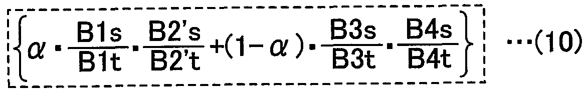

Claims
Priority Applications (4)
| Application Number | Priority Date | Filing Date | Title |
|---|---|---|---|
| CN200980117731.1A CN102159804B (zh) | 2008-05-16 | 2009-05-18 | 内燃机的炭烟排放量估计装置 |
| JP2010512045A JP5126554B2 (ja) | 2008-05-16 | 2009-05-18 | 内燃機関のすす排出量推定装置 |
| US12/812,406 US8457905B2 (en) | 2008-05-16 | 2009-05-18 | Soot discharge estimating device for internal combustion engines |
| EP09746713.8A EP2275652A4 (en) | 2008-05-16 | 2009-05-18 | SOIL DISCHARGE ASSESSMENT DEVICE FOR INTERNAL COMBUSTION ENGINES |
Applications Claiming Priority (3)
| Application Number | Priority Date | Filing Date | Title |
|---|---|---|---|
| JP2008-129039 | 2008-05-16 | ||
| JP2008-12039 | 2008-05-16 | ||
| JP2008129039 | 2008-05-16 |
Publications (2)
| Publication Number | Publication Date |
|---|---|
| WO2009139507A1 true WO2009139507A1 (ja) | 2009-11-19 |
| WO2009139507A8 WO2009139507A8 (ja) | 2010-05-27 |
Family
ID=41318852
Family Applications (1)
| Application Number | Title | Priority Date | Filing Date |
|---|---|---|---|
| PCT/JP2009/059474 Ceased WO2009139507A1 (ja) | 2008-05-16 | 2009-05-18 | 内燃機関のすす排出量推定装置 |
Country Status (5)
| Country | Link |
|---|---|
| US (1) | US8457905B2 (ja) |
| EP (1) | EP2275652A4 (ja) |
| JP (1) | JP5126554B2 (ja) |
| CN (1) | CN102159804B (ja) |
| WO (1) | WO2009139507A1 (ja) |
Cited By (2)
| Publication number | Priority date | Publication date | Assignee | Title |
|---|---|---|---|---|
| JP2015124622A (ja) * | 2013-12-25 | 2015-07-06 | 株式会社デンソー | すす排出量推定装置 |
| JP2020133401A (ja) * | 2019-02-12 | 2020-08-31 | トヨタ自動車株式会社 | 内燃機関の排気浄化装置 |
Families Citing this family (8)
| Publication number | Priority date | Publication date | Assignee | Title |
|---|---|---|---|---|
| WO2010140263A1 (ja) * | 2009-06-03 | 2010-12-09 | トヨタ自動車株式会社 | 内燃機関のすす排出量推定装置 |
| DE102010056514A1 (de) * | 2010-12-31 | 2012-07-05 | Fev Gmbh | NOX-Regelung mit innerer und äußerer Abgasrückführung |
| JP5907123B2 (ja) * | 2012-07-13 | 2016-04-20 | 井関農機株式会社 | スート堆積演算表示装置 |
| JP6611694B2 (ja) * | 2015-12-15 | 2019-11-27 | 株式会社堀場製作所 | 排ガス計測システム |
| CN109306892B (zh) * | 2018-09-19 | 2021-05-11 | 无锡威孚力达催化净化器有限责任公司 | 一种计算柴油机碳烟值的方法及装置 |
| CN112096532B (zh) * | 2019-06-18 | 2023-03-14 | 北京福田康明斯发动机有限公司 | 限制燃油喷射量的方法及其系统 |
| CN110671176B (zh) * | 2019-09-24 | 2020-10-30 | 潍柴动力股份有限公司 | 一种基于氧浓度变化的碳载量计算方法及计算模块 |
| CN115324696B (zh) * | 2022-08-30 | 2023-12-15 | 潍柴动力股份有限公司 | 一种烟度控制方法、装置及车辆 |
Citations (6)
| Publication number | Priority date | Publication date | Assignee | Title |
|---|---|---|---|---|
| JP2006226119A (ja) * | 2005-02-15 | 2006-08-31 | Denso Corp | 内燃機関の排気ガス浄化装置 |
| JP2006316682A (ja) * | 2005-05-12 | 2006-11-24 | Honda Motor Co Ltd | 内燃機関の排気浄化装置 |
| JP2007023959A (ja) * | 2005-07-20 | 2007-02-01 | Nissan Motor Co Ltd | Pm堆積量推定装置 |
| JP2007046477A (ja) | 2005-08-08 | 2007-02-22 | Toyota Motor Corp | 内燃機関のすす発生量推定装置 |
| JP2008031874A (ja) * | 2006-07-26 | 2008-02-14 | Mazda Motor Corp | エンジンの排気浄化装置 |
| JP2008057486A (ja) * | 2006-09-01 | 2008-03-13 | Toyota Motor Corp | 内燃機関の排気浄化装置 |
Family Cites Families (14)
| Publication number | Priority date | Publication date | Assignee | Title |
|---|---|---|---|---|
| JPH11148412A (ja) | 1997-11-19 | 1999-06-02 | Nissan Motor Co Ltd | ディーゼルエンジンの制御装置 |
| JP2001207830A (ja) * | 2000-01-21 | 2001-08-03 | Toyota Motor Corp | パティキュレートフィルタの捕集量判定装置 |
| US6823268B2 (en) * | 2002-02-04 | 2004-11-23 | Avl North America Inc. | Engine exhaust emissions measurement correction |
| JP2003286879A (ja) | 2002-03-27 | 2003-10-10 | Mazda Motor Corp | ディーゼルエンジンの燃焼制御装置 |
| JP4123811B2 (ja) * | 2002-04-15 | 2008-07-23 | トヨタ自動車株式会社 | ディーゼル機関のパティキュレート排出量推定装置 |
| JP4128062B2 (ja) | 2002-10-15 | 2008-07-30 | 株式会社鶴見製作所 | 真空排気装置 |
| JP2004183581A (ja) * | 2002-12-04 | 2004-07-02 | Mitsubishi Motors Corp | 内燃機関の排気浄化装置 |
| JP2004204821A (ja) | 2002-12-26 | 2004-07-22 | Nissan Diesel Motor Co Ltd | 連続再生式トラップフィルタの粒子状物質堆積量検出方法及び装置 |
| JP4111094B2 (ja) | 2003-07-31 | 2008-07-02 | 日産自動車株式会社 | 排気後処理装置付過給エンジンの制御装置および制御方法 |
| JP4251123B2 (ja) * | 2003-11-04 | 2009-04-08 | 株式会社デンソー | 内燃機関 |
| JP2006046299A (ja) | 2004-08-09 | 2006-02-16 | Toyota Motor Corp | 圧縮着火内燃機関の燃焼制御システム |
| DE102005057571A1 (de) * | 2005-12-02 | 2007-06-06 | Robert Bosch Gmbh | Verfahren zur Ansteuerung eines Kraftstoff-Injektors eines Dieselmotors |
| US7426922B2 (en) | 2006-07-26 | 2008-09-23 | Mazda Motor Corporation | Engine exhaust gas purifier |
| WO2010140263A1 (ja) * | 2009-06-03 | 2010-12-09 | トヨタ自動車株式会社 | 内燃機関のすす排出量推定装置 |
-
2009
- 2009-05-18 EP EP09746713.8A patent/EP2275652A4/en not_active Withdrawn
- 2009-05-18 WO PCT/JP2009/059474 patent/WO2009139507A1/ja not_active Ceased
- 2009-05-18 CN CN200980117731.1A patent/CN102159804B/zh not_active Expired - Fee Related
- 2009-05-18 JP JP2010512045A patent/JP5126554B2/ja not_active Expired - Fee Related
- 2009-05-18 US US12/812,406 patent/US8457905B2/en not_active Expired - Fee Related
Patent Citations (6)
| Publication number | Priority date | Publication date | Assignee | Title |
|---|---|---|---|---|
| JP2006226119A (ja) * | 2005-02-15 | 2006-08-31 | Denso Corp | 内燃機関の排気ガス浄化装置 |
| JP2006316682A (ja) * | 2005-05-12 | 2006-11-24 | Honda Motor Co Ltd | 内燃機関の排気浄化装置 |
| JP2007023959A (ja) * | 2005-07-20 | 2007-02-01 | Nissan Motor Co Ltd | Pm堆積量推定装置 |
| JP2007046477A (ja) | 2005-08-08 | 2007-02-22 | Toyota Motor Corp | 内燃機関のすす発生量推定装置 |
| JP2008031874A (ja) * | 2006-07-26 | 2008-02-14 | Mazda Motor Corp | エンジンの排気浄化装置 |
| JP2008057486A (ja) * | 2006-09-01 | 2008-03-13 | Toyota Motor Corp | 内燃機関の排気浄化装置 |
Non-Patent Citations (1)
| Title |
|---|
| See also references of EP2275652A4 * |
Cited By (2)
| Publication number | Priority date | Publication date | Assignee | Title |
|---|---|---|---|---|
| JP2015124622A (ja) * | 2013-12-25 | 2015-07-06 | 株式会社デンソー | すす排出量推定装置 |
| JP2020133401A (ja) * | 2019-02-12 | 2020-08-31 | トヨタ自動車株式会社 | 内燃機関の排気浄化装置 |
Also Published As
| Publication number | Publication date |
|---|---|
| EP2275652A4 (en) | 2015-12-16 |
| US8457905B2 (en) | 2013-06-04 |
| JP5126554B2 (ja) | 2013-01-23 |
| CN102159804B (zh) | 2014-03-26 |
| EP2275652A1 (en) | 2011-01-19 |
| US20100286930A1 (en) | 2010-11-11 |
| CN102159804A (zh) | 2011-08-17 |
| JPWO2009139507A1 (ja) | 2011-09-22 |
| WO2009139507A8 (ja) | 2010-05-27 |
Similar Documents
| Publication | Publication Date | Title |
|---|---|---|
| WO2009139507A1 (ja) | 内燃機関のすす排出量推定装置 | |
| JP4424242B2 (ja) | 内燃機関の混合気状態推定装置、及びエミッション発生量推定装置 | |
| CN100582463C (zh) | 用于内燃机的混合气点火时间估计装置和用于内燃机的控制装置 | |
| CN102400797B (zh) | 用于操作压缩点火发动机的方法和装置 | |
| JP4603951B2 (ja) | 内燃機関のすす発生量推定装置 | |
| JP2004156458A (ja) | 内燃機関のegrガス流量推定装置 | |
| JP5686195B2 (ja) | 内燃機関の制御装置 | |
| CN101598070A (zh) | 用于获得内燃机气缸中燃烧开始的方法和装置 | |
| JP5549784B2 (ja) | 内燃機関の制御装置 | |
| CN102803669B (zh) | 内燃机的碳烟排放量推断装置 | |
| US20170356377A1 (en) | Controller for internal combustion engine | |
| EP1544443A1 (en) | Method of estimating the in cylinder temperature after combustion | |
| JP4958850B2 (ja) | 内燃機関の混合気温度推定装置 | |
| JP4692179B2 (ja) | 内燃機関の混合気濃度推定装置 | |
| JP4594260B2 (ja) | 内燃機関の混合気の不均一度取得装置、及び混合気状態取得装置 | |
| JP5375979B2 (ja) | 内燃機関の燃焼制御装置 | |
| JP4196798B2 (ja) | 内燃機関の筒内ガス温度推定方法、及び筒内ガス圧力推定方法 | |
| Asad et al. | Transient build-up and effectiveness of diesel exhaust gas recirculation | |
| JP2005180219A (ja) | 内燃機関のNOx発生量推定モデルの学習方法 | |
| JP4775303B2 (ja) | 内燃機関の燃料噴射時期決定装置 | |
| JP2016169723A (ja) | 噴霧干渉判定装置、気流制御装置 |
Legal Events
| Date | Code | Title | Description |
|---|---|---|---|
| WWE | Wipo information: entry into national phase |
Ref document number: 200980117731.1 Country of ref document: CN |
|
| 121 | Ep: the epo has been informed by wipo that ep was designated in this application |
Ref document number: 09746713 Country of ref document: EP Kind code of ref document: A1 |
|
| WWE | Wipo information: entry into national phase |
Ref document number: 2010512045 Country of ref document: JP |
|
| WWE | Wipo information: entry into national phase |
Ref document number: 12812406 Country of ref document: US |
|
| REEP | Request for entry into the european phase |
Ref document number: 2009746713 Country of ref document: EP |
|
| WWE | Wipo information: entry into national phase |
Ref document number: 2009746713 Country of ref document: EP |
|
| NENP | Non-entry into the national phase |
Ref country code: DE |