WO2009144907A1 - ガス絶縁開閉器 - Google Patents
ガス絶縁開閉器 Download PDFInfo
- Publication number
- WO2009144907A1 WO2009144907A1 PCT/JP2009/002280 JP2009002280W WO2009144907A1 WO 2009144907 A1 WO2009144907 A1 WO 2009144907A1 JP 2009002280 W JP2009002280 W JP 2009002280W WO 2009144907 A1 WO2009144907 A1 WO 2009144907A1
- Authority
- WO
- WIPO (PCT)
- Prior art keywords
- gas
- arc
- insulated switch
- extinguishing
- sealed container
- Prior art date
- Legal status (The legal status is an assumption and is not a legal conclusion. Google has not performed a legal analysis and makes no representation as to the accuracy of the status listed.)
- Ceased
Links
Images


Classifications
-
- H—ELECTRICITY
- H01—ELECTRIC ELEMENTS
- H01H—ELECTRIC SWITCHES; RELAYS; SELECTORS; EMERGENCY PROTECTIVE DEVICES
- H01H33/00—High-tension or heavy-current switches with arc-extinguishing or arc-preventing means
- H01H33/02—Details
- H01H33/04—Means for extinguishing or preventing arc between current-carrying parts
- H01H33/22—Selection of fluids for arc-extinguishing
-
- H—ELECTRICITY
- H01—ELECTRIC ELEMENTS
- H01H—ELECTRIC SWITCHES; RELAYS; SELECTORS; EMERGENCY PROTECTIVE DEVICES
- H01H33/00—High-tension or heavy-current switches with arc-extinguishing or arc-preventing means
- H01H33/02—Details
- H01H33/53—Cases; Reservoirs, tanks, piping or valves, for arc-extinguishing fluid; Accessories therefor, e.g. safety arrangements, pressure relief devices
- H01H33/56—Gas reservoirs
- H01H2033/566—Avoiding the use of SF6
-
- H—ELECTRICITY
- H01—ELECTRIC ELEMENTS
- H01H—ELECTRIC SWITCHES; RELAYS; SELECTORS; EMERGENCY PROTECTIVE DEVICES
- H01H33/00—High-tension or heavy-current switches with arc-extinguishing or arc-preventing means
- H01H33/02—Details
- H01H33/53—Cases; Reservoirs, tanks, piping or valves, for arc-extinguishing fluid; Accessories therefor, e.g. safety arrangements, pressure relief devices
- H01H33/56—Gas reservoirs
- H01H2033/567—Detection of decomposition products of the gas
-
- H—ELECTRICITY
- H01—ELECTRIC ELEMENTS
- H01H—ELECTRIC SWITCHES; RELAYS; SELECTORS; EMERGENCY PROTECTIVE DEVICES
- H01H33/00—High-tension or heavy-current switches with arc-extinguishing or arc-preventing means
- H01H33/70—Switches with separate means for directing, obtaining, or increasing flow of arc-extinguishing fluid
- H01H33/88—Switches with separate means for directing, obtaining, or increasing flow of arc-extinguishing fluid the flow of arc-extinguishing fluid being produced or increased by movement of pistons or other pressure-producing parts
- H01H33/90—Switches with separate means for directing, obtaining, or increasing flow of arc-extinguishing fluid the flow of arc-extinguishing fluid being produced or increased by movement of pistons or other pressure-producing parts this movement being effected by or in conjunction with the contact-operating mechanism
- H01H33/91—Switches with separate means for directing, obtaining, or increasing flow of arc-extinguishing fluid the flow of arc-extinguishing fluid being produced or increased by movement of pistons or other pressure-producing parts this movement being effected by or in conjunction with the contact-operating mechanism the arc-extinguishing fluid being air or gas
Definitions
- This invention relates to a gas insulated switch, and more particularly to a gas insulated switch that suppresses the use of greenhouse gases.
- switches that have a current interrupt function, such as load switches, disconnectors, and circuit breakers, depending on the purpose of use and the functions required. Many of them are equipped with electrical contacts that can be mechanically opened and closed in the gas, and when they are energized, they are energized by keeping them in contact, and when the current is interrupted, the electrical contacts are dissociated to generate an arc discharge in the gas. The current is cut off by extinguishing the arc.
- SF 6 gas or air is often used as the arc extinguishing gas.
- SF 6 gas is excellent in arc extinguishing performance (arc extinguishing performance) and electrical insulation performance, and is widely used particularly in high voltage switches.
- Air is often used especially in small switches because of its low cost, safety and environmental friendliness.
- SF 6 gas can be said to be a very suitable gas particularly in a high-voltage switch, it is known to have a high global warming action, and in recent years, reduction of its use amount is desired.
- the magnitude of the global warming action is generally expressed by the global warming coefficient, that is, the relative value when CO 2 gas is 1, and the global warming coefficient of SF 6 gas is known to reach 23,900. Yes. Air is superior in terms of safety and environmental protection, but its arc extinguishing performance and electrical insulation performance are significantly inferior to those of SF 6 gas, so it is difficult to apply widely to high voltage switches. Yes, and is considered to be limited to low to medium voltage applications.
- Non-Patent Document 1 it has been proposed to apply CO 2 gas as an arc extinguishing gas in a switch. Since CO 2 gas has a much smaller global warming effect than SF 6 gas, CO 2 gas can be applied to the switch instead of SF 6 gas to greatly suppress the impact on global warming. Is possible. Moreover, although the arc extinguishing performance and electrical insulation performance of CO 2 gas are inferior to those of SF 6 gas, it is known that the arc extinguishing performance is much better than air, and the insulation performance is equivalent or better. Yes. Therefore, by applying CO 2 gas in place of SF 6 gas or air, it is possible to provide an environmentally friendly switch having generally good performance and suppressing the influence on global warming. .
- Non-patent document 2 perfluorocarbon such as CF 4 gas and hydrofluorocarbon such as CH 2 F 2 gas are applied as arc extinguishing gas of the switch.
- CF 3 I gas Patent Document 3
- These gases are also considered to be effective in reducing the environmental load of the switch because they have less influence on global warming than SF 6 gas and have relatively high arc extinguishing performance and insulation performance.
- Patent Document 4 proposes a measure for preventing electrical quality degradation due to the above.
- Patent Document 5 In addition, in a hybrid circuit breaker having two pairs of electrodes that can be contacted / separated and one of which is a vacuum circuit breaker, one using a mixed gas containing CH 4 as an insulating gas in one arc extinguishing chamber has been proposed. (Patent Document 5).
- CO 2 gas, perfluorocarbon, hydrofluorocarbon, and CF 3 I gas are applied as the electrical insulation medium and arc extinguishing medium of the switch, resulting in global warming compared to conventional switches using SF 6 gas. It has been proposed to provide a switch with reduced impact on the device and having generally good performance.
- the conventional piston Compared with the gas circuit breaker mainly composed of mechanical compression by, the gas temperature is inevitably higher.
- the temperature of the gas is increased, specifically, when the temperature of the gas is increased to about 3000 K or more, dissociation of gas molecules proceeds remarkably and carbon is easily generated. Therefore, if the gas is applied to a puffer-type gas circuit breaker and an attempt is made to obtain a high puffer chamber pressure by actively using the thermal energy of the arc, there is a concern that carbon is easily generated and the quality is impaired. there were.
- perfluorocarbon, hydrofluorocarbon, and CF 3 I gas are artificial gases that do not exist in nature like SF 6 gas, although their global warming potential is lower than SF 6 gas. Therefore, when these are applied to switches and produced in large quantities, they will generate new greenhouse gases on the earth, which is not necessarily environmentally friendly.
- the third problem is that most of the gases belonging to CF 3 I gas, perfluorocarbon, and hydrofluorocarbon have a complicated molecular structure. It was likely to be a molecule. Depending on the current value to be cut off and gas conditions, for example, once CF 3 I gas is dissociated by arc, it is recombined with I 2 and C 2 F 6 or the like, and C 2 F 6 gas is similarly Furthermore, there was a possibility that the molecular structure would be changed to a simple CF 4 or the like. For this reason, when these gases are applied to a switch, the composition of the gas changes each time the current is cut off, and the performance that was initially expected may not be obtained gradually.
- the fourth problem relates to CO 2 and O 2 or a mixed gas of CO 2 and H 2 . These gases are all naturally derived and are truly environmentally friendly. Further, as already proposed in Patent Document 4, by mixing an appropriate amount of O 2 and H 2 , the generation of free carbon after the current interruption mentioned as the first problem while using CO 2 Can be suppressed to some extent.
- O 2 gas is a representative substance that promotes deterioration of organic materials and metals, it is particularly difficult to detect organic conductors such as metal conductors that are exposed to high-temperature environments due to energization, rubber packing, insulators, and lubricating grease. Deterioration has been significantly promoted, resulting in problems such as shortening the life of the equipment and increasing the number of maintenance inspections.
- the insulating nozzle is exposed to an arc reaching tens of thousands of degrees, so that the damage becomes more severe as the concentration of O 2 gas having supporting property increases, and it burns when the current value or gas pressure is high. There was also a possibility of end.
- the mixed gas of CO 2 and H 2 has problems in terms of safety, electrical insulation, and airtightness.
- H 2 gas has a very fast combustion speed among flammable gases, and the explosion range in air is extremely wide at 4 to 75%, causing an explosion if leaked during equipment operation or gas handling. The risk was high.
- H 2 gas is excellent in current interruption performance, the insulation performance is extremely low, which is about 10% or less of CO 2 gas. For this reason, when H 2 is mixed, it is necessary to increase the insulation gap length in order to ensure sufficient insulation performance, and this leads to an increase in the size of the device.
- H 2 gas since H 2 gas has small molecules, it is difficult to ensure airtightness, and it has been necessary to devise measures such as double gas packing in order to ensure confidentiality.
- Patent Documents 5 and 6 propose using one of two arc-extinguishing chambers using a mixed gas containing CH 4 or N 2 as an insulating gas. It cannot be said that it is shown.
- the object of the present invention is to provide a gas-insulated switch that eliminates all the above-mentioned problems, has a small impact on global warming, has excellent performance and quality, and is highly safe.
- At least one pair of electrical contacts is disposed in a sealed container filled with an arc extinguishing gas, and the electrical contacts are energized when energized. It is configured to energize by maintaining the contact state, dissociate the electrical contacts when the current is interrupted to generate arc discharge in the arc extinguishing gas, and interrupt the current by extinguishing the arc.
- the arc-extinguishing gas is a mixed gas mainly containing CO 2 gas and CH 4 gas, and contains 5% or more of CH 4 gas.
- At least one pair of electrical contacts is disposed in a sealed container filled with an arc extinguishing gas, and the electrical contacts are brought into contact when energized.
- a gas-insulated switch configured to cut off the electric current by dissociating the electrical contacts to generate an arc discharge in the arc-extinguishing gas when the current is interrupted and maintaining the current by interrupting the arc.
- the arc extinguishing gas is a mixed gas mainly composed of N 2 gas and CH 4 gas, and contains 30% or more of CH 4 gas.
- H 2 gas a graph illustrating the explosive range in air of CH 4 gas.
- CO 2 gas, O 2 gas, CH 4 gas a table showing the relative comparison of the withstand voltage performance of the H 2 gas.
- the fragmentary longitudinal cross-section which shows the principal part in the airtight container of 4th Embodiment of the gas insulated switch which concerns on this invention.
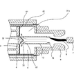
- FIG. 1 is a longitudinal sectional view of an essential part of a first embodiment of a gas insulated switch according to the present invention, showing a state in the middle of a blocking operation.
- This gas insulated switch is a protective switch for a high-voltage power transmission system of, for example, 72 kV or more, and is a puffer type gas circuit breaker.
- Each component shown in FIG. 1 basically has a coaxial cylindrical shape that is axisymmetric about a central axis (not shown) extending in the left-right direction in FIG.
- the sealed container 1 made of grounded metal or insulator or the like contains 5% or more of CH 4 gas, which is a mixed gas of CO 2 gas and CH 4 gas as the arc extinguishing gas 31a. Adopt things.
- a mixed gas of CO 2 (70%) + CH 4 (30%) will be specifically described as an example.
- the CO 2 gas and CH 4 gas used here are preferably those recovered from the atmosphere, or those recovered and purified from what is generated in the course of organic waste treatment and released to the atmosphere. To do.
- a fixed contact portion 21 and a movable contact portion 22 are arranged opposite to each other in the sealed container 1, and the fixed contact portion 21 and the movable contact portion 22 are provided with a fixed arc contact 7a and a movable arc contact 7b, respectively.
- the fixed arc contact 7a and the movable arc contact 7b are in a contact conduction state during normal operation, and are separated by an axial relative movement during an interruption operation, and between the fixed arc contact 7a and the movable arc contact 7b.
- An arc 8 is generated in the space.
- a material such as a copper-tungsten alloy, that has little melt damage to the arc and high mechanical strength.
- a gas flow generating means for blowing arc extinguishing gas 31a as a gas flow to the arc 8 is installed.
- the gas flow generating means a piston 3, a cylinder 4, a puffer chamber 5, and an insulating nozzle 6 are provided.
- a metal exhaust tube 9 through which the fixed-side hot gas flow 11a can pass is attached to the fixed contact portion 21 side.
- a hollow rod 12 through which the movable-side hot gas flow 11b can pass is connected to the movable arc contact 7b.
- the solid insulator 23 for example, an epoxy-based material blended with a filler such as silica is used.
- decomposition gas such as HF is generated by the arc interruption process, and silica may be attacked by the HF gas, so that the characteristics may be deteriorated.
- filler materials are used.
- an epoxy-based material blended with a filler such as silica can be used.
- the arc extinguishing gas 31a sprayed on the high-temperature arc 8 is in a high temperature state, and flows as a fixed-side hot gas flow 11a and a movable-side hot gas flow 11b away from the space between both arc contacts. Is diffused into the sealed container 1.
- grease (not shown) is often applied to a sliding portion such as a gap between the cylinder 4 and the piston 3 in order to reduce friction.
- the pressure increase in the puffer chamber 5 is configured not only by mechanical compression by the piston 3 but also by positively taking in heat energy from the arc 8 into the puffer chamber 5.
- the movable hot gas flow 11 b flowing through the hollow rod 12 is taken into the puffer chamber 5 through the communication hole 33 by the guide 32 and contributes to an increase in pressure in the same portion. It is configured as follows.
- the global warming potential of CO 2 gas and CH 4 gas is said to be 1 and 21, respectively.
- 23,900 which is the SF 6 gas that has been widely used as an insulation and arc-extinguishing medium for conventional switches.
- the impact on the global environment is extremely small.
- SF 6 gas and perfluorocarbon, hydrofluorocarbon, CF 3 I gas, etc. that have been proposed as alternative media, it is a naturally-occurring gas that has the potential to cause artificial environmental damage. rare.
- CO 2 gas used herein, CH 4 gas originally recovered from the atmosphere, or the original because they are used to recover what was released into the atmosphere, CO 2 gas as this purpose, CH 4
- the use of gas does not mean that these gases are newly produced on the earth. Therefore, by using a mixed gas of CO 2 gas and CH 4 gas as an insulating / arcing medium for the switch, the influence on the environment can be extremely reduced.
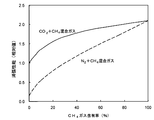
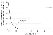
- FIG. 2 is a graph showing analysis values of the amount of free carbon generated when an arc is generated in a CH 4 gas, CO 2 gas, CO 2 + CH 4 mixed gas, or CO 2 + O 2 mixed gas.
- CH 4 is mixed up to 30% as in the example of the present embodiment, the amount of carbon generated can be suppressed to about 10%, and quality deterioration due to carbon generation can be prevented.
- This also eliminates or alleviates the use of arc heat with respect to the increase in puffer chamber pressure so as not to generate carbon, and thus provides a compact switch capable of interrupting a large current. it can.
- the performance of the gas itself is improved over that of CO 2 alone by mixing CH 4 gas.
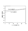
- FIG. 3 is a graph showing arc extinguishing performance of CH 4 gas, CO 2 gas, N 2 gas, CO 2 + CH 4 mixed gas, and N 2 + CH 4 mixed gas.
- FIG. 4 is a graph showing the dielectric strength of CH 4 gas, CO 2 gas, N 2 gas, CO 2 + CH 4 mixed gas, and N 2 + CH 4 mixed gas.
- the cutoff performance and insulation performance are improved to about 1.7 times and 1.1 times, respectively, compared with the case of CO 2 alone. Can do. For this reason, since high interruption
- CO 2 and CH 4 have the lowest molecular structure composed of C, O, and H elements, that is, a simple molecular structure, they are complicated such as perfluorocarbon, gas belonging to hydrofluorocarbon, and CF 3 I gas. Unlike gas with a simple molecular structure, there is almost no possibility of changing to another molecular structure even in the process of recombination even if the molecule is dissociated by an arc, and basically the mixture ratio remains almost completely. Return to CO 2 and CH 4 . Therefore, even if the current is interrupted many times, a situation in which the device characteristics change does not occur, and stable quality can be maintained for a long time.
- 1 mole of CH 4 gas combines with 2 moles of O 2 gas, ie, burns to generate heat.
- the amount of heat necessary for dissociating 2 moles of CO 2 gas even when heated in a mixed gas of CO 2 gas and CH 4 gas and 2 moles of O 2 generated by dissociation and 1 mole of CH 4 are combined.
- the concentration of combustible CH 4 gas is diluted with CO 2 gas, so that the safety when the sealed gas leaks into the atmosphere is high.
- a pair of electrical contacts that is, when a sufficient breaking performance cannot be achieved with only one breaking point, two pairs of electrical contacts may be connected in series to ensure the performance. Due to the excellent characteristics of the mixed gas of CO 2 gas and CH 4 gas, a high shut-off performance can be obtained even at only one shut-off point, so that a small and low-cost switch can be provided.
- a gas insulated switch having a small size, low cost, and high safety, which has a small influence on global warming and has excellent performance and quality. Is possible.
- FIG. 5 is a longitudinal sectional view of a main part of a second embodiment of the gas insulated switch according to the present invention, and shows a state in the middle of a blocking operation.
- the basic configuration is the same as that of the first embodiment shown in FIG. 1, but there are differences in the following points.
- the arc extinguishing gas 31b sealed in the sealed container 1 as in the arc extinguishing gas 31a of the first embodiment, it is a mixed gas of CO 2 gas and CH 4 gas, and CH A gas containing 5% or more of 4 gases is adopted.
- the closed container 1 is provided with a lid 36 for internal inspection, and is sealed with a fastening bolt 37.
- a packing 38 is provided at the joint of the lid 36 to maintain the airtightness of the arc extinguishing gas 31b filled therein.
- the packing 38 for example, any of nitrile rubber, fluorine rubber, silicone rubber, acrylic rubber, ethylene propylene rubber, ethylene propylene diene rubber, butyl rubber, urethane rubber, hyperon, and EVA resin is used.
- Lubricating grease 39 is applied to the surface that slides when the fixed arc contact 7a and the movable arc contact 7b are dissociated, specifically the outer peripheral surface of the cylinder 4, for example, to reduce friction. . Silicone grease is used for this grease.
- At least a part of the metal surface that is not subjected to contact energization specifically, for example, the outer peripheral surface of the fixed contact portion 21 and the movable contact portion 22, and the inner surface of the exhaust tube 9, are phosphoric acid-treated film, alumina film, fluorine-based coating, A surface treatment film 40 such as painting is applied.
- an adsorbent 34 capable of preferentially absorbing moisture is disposed in the sealed container 1 by a case 35.
- CO gas or O 3 gas detection means is provided in the sealed container 1.
- a sensor 51 capable of detecting CO gas or O 3 gas is installed in the sealed container 1, and the information is read by the analyzer 52.
- it may be configured such that only a small amount of gas in the sealed container 1 can be collected in the sampling container 53, and the CO gas and gas contents in the collected gas are separately analyzed by an analyzer.
- An alarm device 41 for detecting CH 4 gas is provided outside the sealed container 1, particularly around a portion sealed by the packing 38, and when it is detected, the alarm device 41 notifies the information by some means.
- the alarm device 41 since the alarm device 41 is arranged, the occurrence of leakage can be always monitored.
- O 2 gas is a typical substance that promotes the deterioration of organic materials and metals, the metal conductor parts that are exposed to high-temperature environments due to energization, rubber packing, insulators, organic substances such as lubricating grease, etc. Deterioration has been promoted remarkably, resulting in problems such as shortening the life of the equipment and increasing the number of maintenance inspections of the equipment. Since the insulating nozzle 6 is exposed to the arc 8 reaching several tens of thousands of degrees, the damage becomes severe as the concentration of the O 2 gas having a supporting property increases, and combustion occurs when the current value or gas pressure is high. There was also the possibility of doing. Further, H 2 gas has problems in terms of safety, electrical insulation, and airtightness.
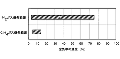
- FIG. 6 is a graph showing the explosion range of H 2 gas and CH 4 gas in the air.
- H 2 gas is a gas that has an extremely fast combustion speed among combustible gases. As shown in Fig. 6, the explosion range in air is extremely wide at 4 to 75%, and it should be leaked during operation or gas handling. There was a risk of explosion.
- the explosion range of CH 4 in the air is 5 to 14%.
- FIG. 7 is a table showing a relative comparison of the withstand voltage performance of CO 2 gas, O 2 gas, CH 4 gas, and H 2 gas.
- H 2 gas is excellent in current interruption performance, the insulation performance is extremely low, which is 10% or less of CO 2 gas as shown in FIG. For this reason, when H 2 is mixed, it is necessary to increase the insulation gap length in order to ensure sufficient insulation performance, and this leads to an increase in the size of the device.
- H 2 gas has small molecules, it is difficult to ensure airtightness, and it has been necessary to devise measures such as double gas packing in order to ensure confidentiality.
- O 3 gas has a strong effect of deteriorating and degrading rubbers used in the packing 38, and there is a concern that the quality and safety of the switch such as gas leakage may be reduced.
- a material with strong resistance to O 3 such as nitrile rubber, fluorine rubber, silicone rubber, acrylic rubber, ethylene propylene rubber, ethylene propylene diene rubber, butyl rubber, urethane rubber, hypalon, EVA resin for packing. Deterioration of the packing 38 can be prevented.
- O 3 gas may promote oxidative deterioration of the lubricating grease 39 used for the sliding surface. Lubricity can be maintained by using silicone grease having high resistance to these.
- the second embodiment described above it is possible to provide a gas insulated switch having a small size, low cost, and high safety, which has a small influence on global warming and has excellent performance and quality. It becomes possible.
- the state of the device can be grasped, and the appropriate inspection and renewal timing can be determined.
- the arc extinguishing gas is a mixed gas of N 2 gas and CH 4 gas and containing 30% or more of CH 4 gas.
- a mixed gas of N 2 (70%) + CH 4 (30%) is specifically taken as an example.
- the CH 4 gas used here is preferably one collected from the atmosphere or one obtained by collecting and purifying one that is generated in the course of organic waste treatment and released to the atmosphere.
- N 2 has a global warming potential of 0 and is the main component of the atmosphere.
- N 2 gas instead of CO 2 , the influence on the environment can be further reduced. Also, it is distributed in large quantities industrially and is inexpensive.
- N 2 does not contain a C element, it does not contribute to carbon generation at all.
- N 2 gas is inferior in arc extinguishing performance and insulation performance compared with CO 2 gas, there is a possibility that the equipment will be increased in size and performance will be reduced.
- FIG. 3 and FIG. 4 by mixing 30% or more of CH 4 with N 2 gas, it is possible to obtain approximately the same blocking performance and insulating performance as those of CO 2 gas alone.
- the third embodiment it is possible to provide a gas-insulated switch having a small size, low cost, and high safety, having a small influence on global warming and having excellent performance and quality. .
- FIG. 8 is a partial vertical cross-sectional view showing the main part in the hermetic container of the fourth embodiment of the gas insulated switch according to the present invention, and shows a state in the middle of the blocking operation.
- the basic configuration of the fourth embodiment is substantially the same as that of the first, second, and third embodiments, but there are differences in the following two points.
- the arc extinguishing gas 31c CH 4 gas or a mixed gas of CO 2 gas and CH 4 gas is used, and O 2 or H 2 gas is further added to 2% or less of these gases.
- the gas added in the range is adopted.
- the arc extinguishing gas is mixed gas of CO 2 gas and CH 4 gas, and O 2 gas corresponding to 2% of the total is mixed therewith.
- the solid element 61 containing O element or H element is disposed at a position exposed to the arc 8 or a gas flow heated by the arc 8. Specific placement locations include, for example, the vicinity of the surface of the guide 32 and the inside of the cylinder 4.
- the material of the solid element 61 for example, polyethylene, polyamide, polymethyl methacrylate, polyacetal, or the like is used.
- gas molecules such as CO 2 and CH 4 are dissociated and separated into various ion particles and electrons.
- the temperature of the arc decreases, and the particles recombine and return to gas molecules.
- O ions are consumed for the oxidation of metals such as the fixed arc contact 7a and the movable arc contact 7b, and a part of O necessary to restore the CO 2 gas is insufficient.
- the H required to restore the CH 4 gas is consumed when the insulating nozzle 6 is combined with the F ions mixed by evaporation and becomes HF gas. and to for example a hydrocarbon gas other than CH 4, such as C 2 H 4 is produced.
- a hydrocarbon gas other than CH 4 such as C 2 H 4 is produced.
- CO gas is a toxic gas, it is preferable to suppress its generation as much as possible.
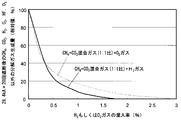
- FIG. 9 is a graph showing the amount of cracked gas produced other than CH 4 , H 2 , HF, and O 3 gas after many interruptions of a large current in the CH 4 + H 2 mixed gas.
- FIG. 10 shows CH 4 + CO 2 + H 2 mixed gas, CH 4 + CO 2 + O 2 mixed gas, and CH 4 , CO 2 , H 2 , O 2 , HF, O 3 after blocking a large current many times. It is a graph which shows the cracked gas production amount other than gas. Each of these figures shows the value after breaking the current of 28.4 kA 20 times. Thus, it can be seen that the generation amount of the above-mentioned decomposition gas is remarkably reduced by additionally mixing about 2% of H 2 gas or O 2 gas.
- HF and O 3 are excluded because these two gases are highly reactive and even if they are generated to some extent. This is because, after the time elapses, the reaction is adsorbed by a secondary reaction or a metal surface in a sealed container and disappears in general.
- H 2 gas or O 2 gas to be additionally mixed is limited to 2% or less of the total, the performance of the switch is not greatly changed by mixing these additional gases.
- H 2 gas or O 2 gas is additionally mixed within a range not exceeding 2%, so that the characteristics of the switch are hardly changed, and a gas such as CO that does not originally exist can be generated. It can be remarkably suppressed.
- the same effect can be obtained by arranging the element 61. This is because when the current is interrupted, the solid element 61 is melted and vaporized by exposure to a high-temperature arc or a high-temperature gas flow, whereby O or H is locally supplied in the vicinity of the arc when the current is interrupted. is there.
- each embodiment described above is merely an example, and the present invention is not limited thereto.
- the arc extinguishing gas component exemplified in each embodiment shows a main component, and may contain other impurity gases.
- the example of the puffer type gas circuit breaker was shown in the said embodiment, this invention is applicable also to another gas insulated switch.
Landscapes
- Gas-Insulated Switchgears (AREA)
- Circuit Breakers (AREA)
- Driving Mechanisms And Operating Circuits Of Arc-Extinguishing High-Tension Switches (AREA)
Abstract
Description
図1は、本発明に係るガス絶縁開閉器の第1の実施形態の要部縦断面図であって、遮断動作途中の状態を示している。このガス絶縁開閉器は、たとえば72kV以上の高電圧送電系統の保護用開閉器であって、パッファ形ガス遮断器である。図1に示す各部品は基本的に、図1の左右方向に延びる中心軸(図示せず)の周りに軸対称な同軸円筒形状である。
図5は、本発明に係るガス絶縁開閉器の第2の実施形態の要部縦断面図であって、遮断動作途中の状態を示している。基本的な構成は図1に示した第1の実施形態と同じであるが、下記の点に相違がある。
つぎに本発明に係るガス絶縁開閉器の第3の実施形態について説明する。この第3の実施形態の基本的な構成は、第1または第2の実施形態と同様であるので図示は省略する。
図8は、本発明に係るガス絶縁開閉器の第4の実施形態の密閉容器内の要部を示す部分縦断面図であって、遮断動作途中の状態を示している。第4の実施形態の基本的な構成は、第1、第2、および第3の実施形態と概ね同じであるが、下記の2点に相違がある。
以上説明した各実施形態は単なる例示であって、本発明はこれらに限定されるものではない。たとえば、各実施形態で例示した消弧性ガスの成分は主たる成分を示したものであって、他の不純物ガスが含まれていてもよい。また、各実施形態の特徴を種々に組み合わせてもよい。また、上記実施形態ではパッファ形ガス遮断器の例を示したが、本発明は他のガス絶縁開閉器にも適用できる。
3…ピストン
4…シリンダ
5…パッファ室
6…絶縁ノズル
7a…固定アーク接触子
7b…可動アーク接触子
8…アーク
9…排気筒
11a…固定側熱ガス流
11b…可動側熱ガス流
12…中空ロッド
21…固定接触部
22…可動接触部
23…固体絶縁物
31a、31b、31c…消弧性ガス
32…ガイド
33…連通穴
34…吸着剤
35…ケース
36…蓋
37…締付ボルト
38…パッキン
39…グリス
40…表面処理皮膜
41…警報装置
51…センサ
52…分析装置
53…サンプリング容器
61…固体素子
Claims (12)
- 消弧性ガスで充たされた密閉容器内に少なくとも1対の電気接点を配置し、通電時には前記電気接点を接触状態に保つことで通電を行ない、電流遮断時には前記電気接点を解離させて前記消弧性ガス中にアーク放電を発生させ、そのアークを消弧することで電流を遮断せしめるよう構成されたガス絶縁開閉器において、
前記消弧性ガスが、CO2ガスとCH4ガスを主成分とする混合ガスであって、CH4ガスを5%以上含むことを特徴とするガス絶縁開閉器。 - 消弧性ガスで充たされた密閉容器内に少なくとも1対の電気接点を配置し、通電時には前記電気接点を接触状態に保つことで通電を行ない、電流遮断時には前記電気接点を解離させて前記消弧性ガス中にアーク放電を発生させ、そのアークを消弧することで電流を遮断せしめるよう構成されたガス絶縁開閉器において、
前記消弧性ガスが、N2ガスとCH4ガスを主成分とする混合ガスであって、CH4ガスを30%以上含むことを特徴とするガス絶縁開閉器。 - 前記密閉容器内に形成されて前記消弧性ガスを蓄積し、前記アークの熱エネルギーにより内部空間内の前記消弧性ガスの圧力が上昇するように構成された蓄圧空間と、
前記蓄圧空間と前記アークとを結ぶガス流路と、
を有し、
前記蓄圧空間に蓄積されて前記アークの熱エネルギーによって昇圧された前記消弧性ガスが前記ガス流路を通って前記アークに吹き付けられるように構成されていること、を特徴とする請求の範囲第1項または第2項に記載のガス絶縁開閉器。 - 前記密閉容器内に、水分を優先的に吸収可能な吸着剤が設置されていることを特徴とする請求の範囲第1項または第2項に記載のガス絶縁開閉器。
- 前記密閉容器内において電圧が印加される部分を電気的に絶縁し、かつ機械的に支持するための固体絶縁支持物が、シリカを配合したエポキシ系材料で製作されていることを特徴とする請求の範囲第1項または第2項に記載のガス絶縁開閉器。
- 前記密閉容器は、前記消弧性ガスを密封するためのパッキンとして、ニトリルゴム、フッ素ゴム、シリコーンゴム、アクリルゴム、エチレンプロピレンゴム、エチレンプロピレンジエンゴム、ブチルゴム、ウレタンゴム、ハイパロン、EVA樹脂のいずれか少なくとも一種を用いていることを特徴とする請求の範囲第1項または第2項に記載のガス絶縁開閉器。
- 前記電気接点を解離動作する際の摺動面に潤滑性のシリコーングリスが塗布されていることを特徴とする請求の範囲第1項または第2項に記載のガス絶縁開閉器。
- 接触通電を行なわない金属表面の少なくとも一部に、燐酸処理皮膜、アルミナ皮膜、フッ素系コーティング、塗装のいずれかの表面処理が施されていることを特徴とする請求の範囲第1項または第2項に記載のガス絶縁開閉器。
- 前記密閉容器内のCOガスもしくはO3ガスを検出する検出手段を有することを特徴とする請求の範囲第1項または第2項に記載のガス絶縁開閉器。
- 前記消弧性ガスが、O2もしくはH2ガスが2%以下の範囲で添加された混合ガスであることを特徴とする請求の範囲第1項または第2項に記載のガス絶縁開閉器。
- 前記アーク、もしくは前記アークにより熱せられた消弧性ガス流に曝される位置に、O元素もしくはH元素を含む固体材料が配置されていることを特徴とする請求の範囲第1項または第2項に記載のガス絶縁開閉器。
- 前記密閉容器内に充填するCH4ガスまたはCO2ガスは、大気中より回収したもの、もしくは成り行きでは大気放出されるものを回収、精製して利用するものであることを特徴とする請求の範囲第1項または第2項に記載のガス絶縁開閉器。
Priority Applications (4)
| Application Number | Priority Date | Filing Date | Title |
|---|---|---|---|
| EP09754416.7A EP2284854B1 (en) | 2008-05-29 | 2009-05-25 | Gas insulated switch |
| BRPI0912282A BRPI0912282A2 (pt) | 2008-05-29 | 2009-05-25 | quadro de distribuição isolado a gás |
| CN200980119698.6A CN102047365B (zh) | 2008-05-29 | 2009-05-25 | 气体绝缘开关装置 |
| US12/955,181 US8304676B2 (en) | 2008-05-29 | 2010-11-29 | Gas insulated switchgear |
Applications Claiming Priority (2)
| Application Number | Priority Date | Filing Date | Title |
|---|---|---|---|
| JP2008-140413 | 2008-05-29 | ||
| JP2008140413A JP5127569B2 (ja) | 2008-05-29 | 2008-05-29 | ガス絶縁開閉器 |
Related Child Applications (1)
| Application Number | Title | Priority Date | Filing Date |
|---|---|---|---|
| US12/955,181 Continuation-In-Part US8304676B2 (en) | 2008-05-29 | 2010-11-29 | Gas insulated switchgear |
Publications (1)
| Publication Number | Publication Date |
|---|---|
| WO2009144907A1 true WO2009144907A1 (ja) | 2009-12-03 |
Family
ID=41376797
Family Applications (1)
| Application Number | Title | Priority Date | Filing Date |
|---|---|---|---|
| PCT/JP2009/002280 Ceased WO2009144907A1 (ja) | 2008-05-29 | 2009-05-25 | ガス絶縁開閉器 |
Country Status (6)
| Country | Link |
|---|---|
| US (1) | US8304676B2 (ja) |
| EP (1) | EP2284854B1 (ja) |
| JP (1) | JP5127569B2 (ja) |
| CN (1) | CN102047365B (ja) |
| BR (1) | BRPI0912282A2 (ja) |
| WO (1) | WO2009144907A1 (ja) |
Cited By (2)
| Publication number | Priority date | Publication date | Assignee | Title |
|---|---|---|---|---|
| JP2023085791A (ja) * | 2021-12-09 | 2023-06-21 | 三菱電機株式会社 | 電力用スイッチギア |
| JP2023544971A (ja) * | 2020-10-09 | 2023-10-26 | ヒタチ・エナジー・スウィツァーランド・アクチェンゲゼルシャフト | 中電圧または高電圧の電気装置を再構築するための方法 |
Families Citing this family (41)
| Publication number | Priority date | Publication date | Assignee | Title |
|---|---|---|---|---|
| EP1947669A1 (de) * | 2007-01-17 | 2008-07-23 | Abb Research Ltd. | Pol für einen gasinsolierten Hochspannungsschalter und Verfahren zur Herstellung eines solchen Schalterpols |
| JP5238622B2 (ja) | 2009-06-17 | 2013-07-17 | 株式会社東芝 | ガス絶縁機器、および、その製造方法 |
| WO2012077436A1 (ja) * | 2010-12-07 | 2012-06-14 | 三菱電機株式会社 | ガス遮断器 |
| US9362071B2 (en) | 2011-03-02 | 2016-06-07 | Franklin Fueling Systems, Inc. | Gas density monitoring system |
| US8492672B2 (en) * | 2011-08-05 | 2013-07-23 | Eaton Corporation | Insulated arc flash arrester |
| JP2015005327A (ja) * | 2011-09-06 | 2015-01-08 | 株式会社日立製作所 | パッファ式ガス遮断器 |
| JP2013054989A (ja) * | 2011-09-06 | 2013-03-21 | Toshiba Corp | ガス遮断器 |
| JP5872260B2 (ja) | 2011-11-22 | 2016-03-01 | 株式会社東芝 | 電力用ガス絶縁機器およびその製造方法 |
| WO2013087684A1 (en) * | 2011-12-13 | 2013-06-20 | Abb Technology Ag | Method and device for determining an operating parameter of a fluid insulated electrical apparatus |
| CN104380419A (zh) | 2012-02-20 | 2015-02-25 | 富兰克林加油系统公司 | 水分监视系统 |
| DE112013001981T5 (de) | 2012-04-11 | 2015-03-12 | Abb Technology Ag | Leistungsschalter |
| CN103108484A (zh) * | 2012-12-26 | 2013-05-15 | 江苏达胜加速器制造有限公司 | 一种高压型加速器 |
| JP2014179301A (ja) * | 2013-03-15 | 2014-09-25 | Toshiba Corp | 電力用ガス絶縁機器及びその運転方法 |
| JP2014200155A (ja) * | 2013-03-29 | 2014-10-23 | 株式会社東芝 | ガス絶縁開閉器 |
| US20150380188A1 (en) * | 2013-04-18 | 2015-12-31 | Hitachi, Ltd. | Gas Circuit Breaker |
| CN104201049A (zh) * | 2013-08-22 | 2014-12-10 | 河南平高电气股份有限公司 | 压气缸-主触头装置及使用该装置的动端和断路器灭弧室 |
| FR3011138B1 (fr) | 2013-09-20 | 2015-10-30 | Alstom Technology Ltd | Appareil electrique moyenne ou haute tension a isolation gazeuse comprenant du dioxyde de carbone, de l'oxygene et de l'heptafluoroisobutyronitrile |
| WO2015071303A1 (en) | 2013-11-12 | 2015-05-21 | Abb Technology Ag | Water and contamination absorber for c02 insulated electrical apparatus for the generation, transmission, distribution and/or usage of electrical energy |
| CN103730290A (zh) * | 2013-12-20 | 2014-04-16 | 吴江市东泰电力特种开关有限公司 | 一种少油电力开关 |
| JP6382543B2 (ja) * | 2014-03-24 | 2018-08-29 | 株式会社東芝 | ガス遮断器 |
| JP6454541B2 (ja) * | 2014-12-25 | 2019-01-16 | 株式会社日立製作所 | ガス絶縁開閉装置用潤滑剤及びガス絶縁開閉装置 |
| US9865405B2 (en) | 2015-02-03 | 2018-01-09 | General Electric Company | Fixed contact for joining a bus bar and a sliding contact of an electrical switchgear |
| DE102015101622A1 (de) * | 2015-02-04 | 2016-08-04 | Rwth Aachen | Leistungsschalter |
| ES2759262T5 (es) | 2015-04-13 | 2022-11-30 | Hitachi Energy Switzerland Ag | Dispositivo para interrumpir solo corrientes que no son de cortocircuito, en particular seccionador o conmutador de puesta a tierra |
| EP3171382A1 (en) * | 2015-11-17 | 2017-05-24 | ABB Schweiz AG | A gas insulated electric apparatus and a method for producing a gas insulated electric apparatus |
| DE202016100268U1 (de) * | 2016-01-21 | 2016-02-25 | Abb Technology Ag | Vorrichtung zur Erzeugung, Übertragung, Verteilung und/oder Verwendung elektrischer Energie oder eine Komponente einer solchen Vorrichtung sowie Gasdichtung für eine solche Vorrichtung oder Komponente |
| CN109952679B (zh) * | 2016-11-14 | 2022-06-14 | 株式会社东芝 | 非水电解质电池及电池包 |
| EP3404686B1 (en) * | 2017-05-18 | 2020-07-08 | General Electric Technology GmbH | A circuit breaker comprising a ceria-based catalyst for co conversion into co2 |
| EP3404687B1 (en) * | 2017-05-18 | 2025-02-19 | General Electric Technology GmbH | A circuit breaker comprising a metal-organic framework material for co adsorption |
| JP2018010875A (ja) * | 2017-09-08 | 2018-01-18 | 株式会社東芝 | ガス遮断器 |
| US11177097B2 (en) * | 2017-12-01 | 2021-11-16 | Kabushiki Kaisha Toshiba | Gas circuit breaker |
| EP3603773A1 (de) * | 2018-07-31 | 2020-02-05 | Siemens Aktiengesellschaft | Gasisolierte elektrische anlage |
| CN109830912A (zh) * | 2019-03-29 | 2019-05-31 | 武汉大学 | 一种环保型气体绝缘介质的改性配方 |
| EP3848951A1 (en) * | 2020-01-07 | 2021-07-14 | ABB Power Grids Switzerland AG | Control scheme for the operation of an electric motor actuator for a medium to high voltage circuit breaker |
| DE102020203029A1 (de) | 2020-03-10 | 2021-09-16 | Siemens Aktiengesellschaft | Elektrische Schaltanordnung |
| WO2022131226A1 (ja) * | 2020-12-16 | 2022-06-23 | Agc株式会社 | 電気設備、充填設備、および貯蔵設備 |
| US11650265B2 (en) | 2021-03-03 | 2023-05-16 | Honeywell International Inc. | Electric meter having gas sensor for arc detection |
| EP4350911B1 (en) * | 2021-05-31 | 2025-12-03 | Mitsubishi Electric Corporation | Gas-insulated apparatus |
| EP4187567B1 (en) * | 2021-11-24 | 2024-06-12 | General Electric Technology GmbH | An electric arc-blast nozzle with improved mechanical strength and a circuit breaker including such a nozzle |
| WO2025032700A1 (ja) * | 2023-08-07 | 2025-02-13 | 株式会社東芝 | 電力用ガス絶縁機器用の診断装置および電力用ガス絶縁機器の診断方法 |
| US20250216458A1 (en) * | 2024-01-03 | 2025-07-03 | Honeywell International Inc. | Sealed high current switch with internal gas monitor |
Citations (9)
| Publication number | Priority date | Publication date | Assignee | Title |
|---|---|---|---|---|
| JPS58158802A (ja) * | 1982-03-17 | 1983-09-21 | 株式会社東芝 | 絶縁ガスおよびガス絶縁機器 |
| JPH0797466A (ja) | 1993-09-28 | 1995-04-11 | Dainippon Ink & Chem Inc | プリプレグ |
| JPH07109744A (ja) | 1993-10-12 | 1995-04-25 | Hitachi Constr Mach Co Ltd | 建設機械の高さ位置制限制御装置 |
| JP2000164040A (ja) | 1998-11-26 | 2000-06-16 | Hitachi Ltd | ガス絶縁電気機器 |
| JP2001189118A (ja) | 1999-12-06 | 2001-07-10 | Abb T & D Technologie Ag | ハイブリッド遮断器 |
| JP2003348721A (ja) | 2002-05-29 | 2003-12-05 | Hitachi Ltd | ガス吹付け遮断器 |
| JP2005328600A (ja) * | 2004-05-13 | 2005-11-24 | Mitsubishi Electric Corp | 密閉型開閉装置 |
| JP2007258137A (ja) | 2006-03-27 | 2007-10-04 | Toshiba Corp | ガス絶縁開閉器 |
| JP2008084768A (ja) * | 2006-09-28 | 2008-04-10 | Toshiba Corp | ガス絶縁開閉器 |
Family Cites Families (6)
| Publication number | Priority date | Publication date | Assignee | Title |
|---|---|---|---|---|
| CN1008415B (zh) * | 1985-09-30 | 1990-06-13 | Bbc勃朗勃威力有限公司 | 气吹开关 |
| JPS63144706A (ja) * | 1986-12-05 | 1988-06-16 | 株式会社東芝 | 絶縁スペ−サ |
| DE19519992C2 (de) * | 1995-05-24 | 2002-03-21 | Siemens Ag | Schaltstrecke für einen mit einem Löschgas arbeitenden Hochspannungs-Leistungsschalter |
| JPH0937420A (ja) * | 1995-07-21 | 1997-02-07 | Toshiba Chem Corp | ガス絶縁開閉装置 |
| DE19958646C2 (de) * | 1999-12-06 | 2001-12-06 | Abb T & D Tech Ltd | Hybridleistungsschalter |
| JP2008075069A (ja) * | 2006-08-23 | 2008-04-03 | Toshiba Corp | 注型樹脂組成物およびそれを用いた絶縁材料、絶縁構造体 |
-
2008
- 2008-05-29 JP JP2008140413A patent/JP5127569B2/ja active Active
-
2009
- 2009-05-25 EP EP09754416.7A patent/EP2284854B1/en active Active
- 2009-05-25 WO PCT/JP2009/002280 patent/WO2009144907A1/ja not_active Ceased
- 2009-05-25 CN CN200980119698.6A patent/CN102047365B/zh active Active
- 2009-05-25 BR BRPI0912282A patent/BRPI0912282A2/pt not_active Application Discontinuation
-
2010
- 2010-11-29 US US12/955,181 patent/US8304676B2/en active Active
Patent Citations (9)
| Publication number | Priority date | Publication date | Assignee | Title |
|---|---|---|---|---|
| JPS58158802A (ja) * | 1982-03-17 | 1983-09-21 | 株式会社東芝 | 絶縁ガスおよびガス絶縁機器 |
| JPH0797466A (ja) | 1993-09-28 | 1995-04-11 | Dainippon Ink & Chem Inc | プリプレグ |
| JPH07109744A (ja) | 1993-10-12 | 1995-04-25 | Hitachi Constr Mach Co Ltd | 建設機械の高さ位置制限制御装置 |
| JP2000164040A (ja) | 1998-11-26 | 2000-06-16 | Hitachi Ltd | ガス絶縁電気機器 |
| JP2001189118A (ja) | 1999-12-06 | 2001-07-10 | Abb T & D Technologie Ag | ハイブリッド遮断器 |
| JP2003348721A (ja) | 2002-05-29 | 2003-12-05 | Hitachi Ltd | ガス吹付け遮断器 |
| JP2005328600A (ja) * | 2004-05-13 | 2005-11-24 | Mitsubishi Electric Corp | 密閉型開閉装置 |
| JP2007258137A (ja) | 2006-03-27 | 2007-10-04 | Toshiba Corp | ガス絶縁開閉器 |
| JP2008084768A (ja) * | 2006-09-28 | 2008-04-10 | Toshiba Corp | ガス絶縁開閉器 |
Non-Patent Citations (3)
| Title |
|---|
| "Global Environmental Load of SF6 and Insulation of SF6 Mixture or Substitute Gas", TECHNICAL REPORT OF THE INSTITUTE OF ELECTRICAL ENGINEERS OF JAPAN, no. 841, 2001 |
| See also references of EP2284854A4 * |
| UCHII; KAWANO; NAKAMOTO; MIZOGUCHI: "Fundamental Properties of C02 Gas as an Arc Extinguishing Medium and Thermal Interruption Performance of Full-Scale Circuit Breaker Model", TRANSACTIONS B OF THE INSTITUTE OF ELECTRICAL ENGINEERS OF JAPAN, vol. 124, no. 3, 2004, pages 469 - 475 |
Cited By (5)
| Publication number | Priority date | Publication date | Assignee | Title |
|---|---|---|---|---|
| JP2023544971A (ja) * | 2020-10-09 | 2023-10-26 | ヒタチ・エナジー・スウィツァーランド・アクチェンゲゼルシャフト | 中電圧または高電圧の電気装置を再構築するための方法 |
| JP7545574B2 (ja) | 2020-10-09 | 2024-09-04 | ヒタチ・エナジー・リミテッド | 中電圧または高電圧の電気装置を再構築するための方法 |
| US12374472B2 (en) | 2020-10-09 | 2025-07-29 | Hitachi Energy Ltd | Method for re-establishing an electrical apparatus of medium or high voltage |
| JP2023085791A (ja) * | 2021-12-09 | 2023-06-21 | 三菱電機株式会社 | 電力用スイッチギア |
| JP7539363B2 (ja) | 2021-12-09 | 2024-08-23 | 三菱電機株式会社 | 電力用スイッチギア |
Also Published As
| Publication number | Publication date |
|---|---|
| EP2284854A1 (en) | 2011-02-16 |
| US8304676B2 (en) | 2012-11-06 |
| BRPI0912282A2 (pt) | 2015-10-20 |
| CN102047365A (zh) | 2011-05-04 |
| JP2009289566A (ja) | 2009-12-10 |
| US20110127237A1 (en) | 2011-06-02 |
| JP5127569B2 (ja) | 2013-01-23 |
| EP2284854B1 (en) | 2014-08-13 |
| CN102047365B (zh) | 2014-01-01 |
| EP2284854A4 (en) | 2014-01-08 |
Similar Documents
| Publication | Publication Date | Title |
|---|---|---|
| JP5127569B2 (ja) | ガス絶縁開閉器 | |
| JP4660407B2 (ja) | ガス絶縁開閉器 | |
| US20120228264A1 (en) | Use of specific composite materials as electric arc extinction materials in electrical equipment | |
| US20090109604A1 (en) | Gas Insulated Switchgear and Gas Circuit Breaker | |
| EP3477675B1 (en) | Gas-insulated medium-voltage switch with shield device | |
| CN106663495A (zh) | 1,1,1,4,4,4‑六氟‑2‑丁烯用作气态电绝缘和/或灭弧介质的设备和方法 | |
| KR102458208B1 (ko) | 전기 에너지 전송 장치용 절연 매체 | |
| Uchii et al. | Investigations on SF6-free gas circuit breaker adopting CO2 gas as an alternative arc-quenching and insulating medium | |
| US12199413B2 (en) | Gas insulation apparatus | |
| CN114072881A (zh) | 介电绝缘或消弧流体 | |
| CN110556265A (zh) | 一种适用于容性负载投切的真空灭弧室的旋转触头结构 | |
| US20230110903A1 (en) | Insulation medium for an electric energy transfer device | |
| EP1556874B1 (en) | Circuit breaker | |
| US20240387125A1 (en) | Gas-insulated high or medium voltage circuit breaker | |
| EP1113475A1 (en) | Arcing contact assembly for medium and/or high voltage circuit breakers | |
| Uchii et al. | ADOPTING CO, GAS AS AN ALTERNATIVE ARC-QUENCHING AND INSULATING MEDIUM | |
| Uchii et al. | ARC-QUENCHING AND INSULATING MEDIUM | |
| CN109904780A (zh) | 基于碳沉积抑制技术的氟碳混合气体绝缘开关装置 | |
| JP2001286017A (ja) | 開閉装置 |
Legal Events
| Date | Code | Title | Description |
|---|---|---|---|
| WWE | Wipo information: entry into national phase |
Ref document number: 200980119698.6 Country of ref document: CN |
|
| 121 | Ep: the epo has been informed by wipo that ep was designated in this application |
Ref document number: 09754416 Country of ref document: EP Kind code of ref document: A1 |
|
| WWE | Wipo information: entry into national phase |
Ref document number: 2009754416 Country of ref document: EP |
|
| NENP | Non-entry into the national phase |
Ref country code: DE |
|
| WWE | Wipo information: entry into national phase |
Ref document number: 8429/CHENP/2010 Country of ref document: IN |
|
| ENP | Entry into the national phase |
Ref document number: PI0912282 Country of ref document: BR Kind code of ref document: A2 Effective date: 20101129 |