WO2009144940A1 - Mea部材及び固体高分子形燃料電池 - Google Patents
Mea部材及び固体高分子形燃料電池 Download PDFInfo
- Publication number
- WO2009144940A1 WO2009144940A1 PCT/JP2009/002356 JP2009002356W WO2009144940A1 WO 2009144940 A1 WO2009144940 A1 WO 2009144940A1 JP 2009002356 W JP2009002356 W JP 2009002356W WO 2009144940 A1 WO2009144940 A1 WO 2009144940A1
- Authority
- WO
- WIPO (PCT)
- Prior art keywords
- mea
- frame
- polymer electrolyte
- main surface
- electrolyte membrane
- Prior art date
- Legal status (The legal status is an assumption and is not a legal conclusion. Google has not performed a legal analysis and makes no representation as to the accuracy of the status listed.)
- Ceased
Links
Images











Classifications
-
- H—ELECTRICITY
- H01—ELECTRIC ELEMENTS
- H01M—PROCESSES OR MEANS, e.g. BATTERIES, FOR THE DIRECT CONVERSION OF CHEMICAL ENERGY INTO ELECTRICAL ENERGY
- H01M8/00—Fuel cells; Manufacture thereof
- H01M8/008—Disposal or recycling of fuel cells
-
- H—ELECTRICITY
- H01—ELECTRIC ELEMENTS
- H01M—PROCESSES OR MEANS, e.g. BATTERIES, FOR THE DIRECT CONVERSION OF CHEMICAL ENERGY INTO ELECTRICAL ENERGY
- H01M8/00—Fuel cells; Manufacture thereof
- H01M8/02—Details
- H01M8/0202—Collectors; Separators, e.g. bipolar separators; Interconnectors
- H01M8/0258—Collectors; Separators, e.g. bipolar separators; Interconnectors characterised by the configuration of channels, e.g. by the flow field of the reactant or coolant
-
- H—ELECTRICITY
- H01—ELECTRIC ELEMENTS
- H01M—PROCESSES OR MEANS, e.g. BATTERIES, FOR THE DIRECT CONVERSION OF CHEMICAL ENERGY INTO ELECTRICAL ENERGY
- H01M8/00—Fuel cells; Manufacture thereof
- H01M8/02—Details
- H01M8/0202—Collectors; Separators, e.g. bipolar separators; Interconnectors
- H01M8/0258—Collectors; Separators, e.g. bipolar separators; Interconnectors characterised by the configuration of channels, e.g. by the flow field of the reactant or coolant
- H01M8/0263—Collectors; Separators, e.g. bipolar separators; Interconnectors characterised by the configuration of channels, e.g. by the flow field of the reactant or coolant having meandering or serpentine paths
-
- H—ELECTRICITY
- H01—ELECTRIC ELEMENTS
- H01M—PROCESSES OR MEANS, e.g. BATTERIES, FOR THE DIRECT CONVERSION OF CHEMICAL ENERGY INTO ELECTRICAL ENERGY
- H01M8/00—Fuel cells; Manufacture thereof
- H01M8/02—Details
- H01M8/0271—Sealing or supporting means around electrodes, matrices or membranes
- H01M8/0273—Sealing or supporting means around electrodes, matrices or membranes with sealing or supporting means in the form of a frame
-
- H—ELECTRICITY
- H01—ELECTRIC ELEMENTS
- H01M—PROCESSES OR MEANS, e.g. BATTERIES, FOR THE DIRECT CONVERSION OF CHEMICAL ENERGY INTO ELECTRICAL ENERGY
- H01M8/00—Fuel cells; Manufacture thereof
- H01M8/02—Details
- H01M8/0271—Sealing or supporting means around electrodes, matrices or membranes
- H01M8/0276—Sealing means characterised by their form
-
- H—ELECTRICITY
- H01—ELECTRIC ELEMENTS
- H01M—PROCESSES OR MEANS, e.g. BATTERIES, FOR THE DIRECT CONVERSION OF CHEMICAL ENERGY INTO ELECTRICAL ENERGY
- H01M8/00—Fuel cells; Manufacture thereof
- H01M8/02—Details
- H01M8/0271—Sealing or supporting means around electrodes, matrices or membranes
- H01M8/028—Sealing means characterised by their material
-
- H—ELECTRICITY
- H01—ELECTRIC ELEMENTS
- H01M—PROCESSES OR MEANS, e.g. BATTERIES, FOR THE DIRECT CONVERSION OF CHEMICAL ENERGY INTO ELECTRICAL ENERGY
- H01M8/00—Fuel cells; Manufacture thereof
- H01M8/24—Grouping of fuel cells, e.g. stacking of fuel cells
- H01M8/2465—Details of groupings of fuel cells
- H01M8/2483—Details of groupings of fuel cells characterised by internal manifolds
-
- H—ELECTRICITY
- H01—ELECTRIC ELEMENTS
- H01M—PROCESSES OR MEANS, e.g. BATTERIES, FOR THE DIRECT CONVERSION OF CHEMICAL ENERGY INTO ELECTRICAL ENERGY
- H01M8/00—Fuel cells; Manufacture thereof
- H01M8/10—Fuel cells with solid electrolytes
- H01M2008/1095—Fuel cells with polymeric electrolytes
-
- Y—GENERAL TAGGING OF NEW TECHNOLOGICAL DEVELOPMENTS; GENERAL TAGGING OF CROSS-SECTIONAL TECHNOLOGIES SPANNING OVER SEVERAL SECTIONS OF THE IPC; TECHNICAL SUBJECTS COVERED BY FORMER USPC CROSS-REFERENCE ART COLLECTIONS [XRACs] AND DIGESTS
- Y02—TECHNOLOGIES OR APPLICATIONS FOR MITIGATION OR ADAPTATION AGAINST CLIMATE CHANGE
- Y02E—REDUCTION OF GREENHOUSE GAS [GHG] EMISSIONS, RELATED TO ENERGY GENERATION, TRANSMISSION OR DISTRIBUTION
- Y02E60/00—Enabling technologies; Technologies with a potential or indirect contribution to GHG emissions mitigation
- Y02E60/30—Hydrogen technology
- Y02E60/50—Fuel cells
-
- Y—GENERAL TAGGING OF NEW TECHNOLOGICAL DEVELOPMENTS; GENERAL TAGGING OF CROSS-SECTIONAL TECHNOLOGIES SPANNING OVER SEVERAL SECTIONS OF THE IPC; TECHNICAL SUBJECTS COVERED BY FORMER USPC CROSS-REFERENCE ART COLLECTIONS [XRACs] AND DIGESTS
- Y02—TECHNOLOGIES OR APPLICATIONS FOR MITIGATION OR ADAPTATION AGAINST CLIMATE CHANGE
- Y02W—CLIMATE CHANGE MITIGATION TECHNOLOGIES RELATED TO WASTEWATER TREATMENT OR WASTE MANAGEMENT
- Y02W30/00—Technologies for solid waste management
- Y02W30/50—Reuse, recycling or recovery technologies
- Y02W30/84—Recycling of batteries or fuel cells
Definitions
- the present invention relates to an MEA member comprising a polymer electrolyte membrane-electrode assembly (MEA) and a frame, and a polymer electrolyte fuel cell provided with this MEA member, wherein the MEA is used to recycle the electrode material and the like.
- MEA polymer electrolyte membrane-electrode assembly
- the present invention relates to a technology for separating and recovering a frame and a frame.
- PEFC Polymer Electrolyte Fuel Cell
- a solid polymer membrane having ion conductivity as an electrolyte.
- a polymer electrolyte membrane for example, a polystyrene-based cation exchange membrane having a sulfonic acid group, an electrolyte membrane comprising a mixture of fluorocarbon sulfonic acid and polyvinylidene fluoride, a perfluorocarbon sulfonic acid membrane, etc. used.
- FIG. 26 is a diagram showing an outline of a power generation system using a polymer electrolyte fuel cell.
- the cell stack 99 of the PEFC comprises a plurality of stacked unit cells 10 which are basic constituent units, and these unit cells 10 are connected in series.
- Each unit cell 10 includes an anode-side separator 9 in which a fuel gas flow channel is formed, and a membrane-electrode assembly 5 (hereinafter referred to as “MEA (Membrane Electrode”) formed by sandwiching a polymer electrolyte membrane between a pair of anode and cathode. Assembly) and the cathode-side separator 8 in which the oxidant gas flow channel is formed are sequentially stacked and provided.
- MEA Membrane Electrode
- PEFC when fuel containing hydrogen is supplied to the anode through the fuel gas channel and oxidant containing oxygen is supplied to the cathode through the oxidant gas channel, the fuel and oxidant react with each other at the anode and the cathode. , Electricity and heat are generated.
- the MEA 5 is in the form of a thin film, and the MEA 5 alone is difficult to handle when assembling the cell stack 99. Therefore, for example, as described in Patent Document 1, there is one in which the "MEA member 7" provided with the frame 6 surrounding the MEA 5 can be handled as one unit, and the handling property of the MEA 5 is improved.
- the frame is provided with a gasket in order to seal the fuel gas, the oxidant gas and the cooling water between the frame and the anode side separator or the cathode side separator so as not to leak.
- the MEA is held inside the frame by holding the peripheral portion of the MEA with the frame.
- the MEA is sandwiched by the frame body under an appropriate pressure, it is difficult to extract only the MEA from the frame body, and if it is attempted to extract the MEA by force, the MEA may be broken. Therefore, in order to separate the MEA and the frame, it is necessary to have a tool for breaking the frame without damaging the MEA.
- the present invention has been made to solve the above-mentioned problems, and it is an MEA member for easily separating the MEA and the frame without damaging the MEA without using a special tool. Intended to provide a structure.
- the MEA member of the present invention comprises a MEA having a polymer electrolyte membrane and a pair of electrodes disposed on both sides of the main surface of the polymer electrolyte membrane, and holding the peripheral portion of the main surface of the MEA from both sides. And a separation part for separating the MEA from the frame, the separation part being provided on the frame.
- An inner peripheral portion of the frame which is a broken line in the form of a broken line for dividing the frame into two or more parts, or is configured to partially clamp the peripheral portion of the MEA. It is a partial pinching part located in.
- the polymer electrolyte fuel cell of the present invention there is provided a pair of the MEA member and a pair of reaction gas flow paths provided on the both sides of the MEA member so as to sandwich the MEA member. And a separator.
- the separation part is a cut line
- the MEA member and the polymer electrolyte fuel cell of the above configuration can cut or destroy a part of the frame along the cut line by picking and pulling a part of the frame.
- the separation portion is a partial pinching portion
- the area of the pinched portion of the MEA is reduced compared to the conventional one.
- the force holding the MEA acting on the MEA from the frame weakens, and it becomes easy to take out the MEA from the frame. Therefore, the MEA and the frame can be easily separated without using a special tool and without damaging the MEA.
- the frame When the separation portion is a cut line, the frame includes a manifold hole penetrating in a thickness direction of the polymer electrolyte membrane, a manifold hole gasket disposed on the frame so as to surround the manifold hole, and The electrode gasket is disposed on the frame so as to surround the electrode, and the cut line is formed with the electrode gasket of the frame when viewed from the thickness direction of the polymer electrolyte membrane. It may be provided on the outer peripheral side than this including the portion and on the inner peripheral side including the portion where the gasket for the manifold hole is formed.
- the cut lines are provided at a portion where the frame of the frame and the peripheral portion of the MEA overlap when viewed from the thickness direction of the polymer electrolyte membrane, and a plurality of them reach the peripheral portion of the MEA It is good that it is formed by the cut of.
- At least a part of the plurality of cuts may be filled with the electrode gasket or the manifold hole gasket.
- the cut line can be used as a groove for providing a gasket in the frame.
- the plurality of cuts may be alternately and continuously provided on the first main surface and the second main surface of the frame.
- the plurality of cuts may be provided on any one of the first main surface and the second main surface of the frame.
- the plurality of cuts may be provided on both sides of the first main surface and the second main surface of the frame so as to be opposed to each other with the peripheral portion of the MEA interposed therebetween.
- the polymer electrolyte membrane may be exposed at a peripheral portion of the MEA, and the frame and the polymer electrolyte membrane may be in contact at a peripheral portion of the MEA.
- the MEA member may be provided with a membrane reinforcing member at the periphery of the polymer electrolyte membrane, and the frame and the membrane reinforcing member may be in contact with each other at the periphery of the MEA.
- the separation portion is a partial pinching portion
- the partial pinching portion is a first projecting piece partially projecting inward from an inner peripheral portion of the frame, and the frame And a second projecting piece partially projecting inward from an inner peripheral portion of the second emboss, and a peripheral edge portion of the MEA is held between the first projecting piece and the second projecting piece. Good.
- the plurality of first projecting pieces are continuously formed at a predetermined interval, and the plurality of second projecting pieces are continuously formed at a predetermined interval,
- the projecting pieces and the second projecting pieces may be alternately disposed in the circumferential direction of the frame.
- the peripheral portion of the MEA is uniformly pinched while the area of the portion where the MEA is pinched is reduced.
- the entire inner peripheral portion may be covered with a thin film. Since the thin film can be easily removed, the MEA can be more firmly held in use, and the MEA and the frame can be easily separated at the time of disassembly.
- the present invention has the following effects.
- the separation portion when the separation portion is a tear line, it is possible to cut or break a portion of the frame along the tear line by picking and pulling a part of the frame.
- the force holding the MEA acting on the MEA from the frame weakens, and the MEA can be easily extracted from the frame.
- the separation part when the separation part is a partial holding part, the area of the part where the MEA is held can be reduced, so the force for holding the MEA is weakened and the MEA can be easily taken out from the frame. . Therefore, the MEA and the frame can be easily separated without damaging the MEA without using a special tool.
- FIG. 12 is a cross-sectional view taken along line XII-XII in FIG.
- FIG. 12 is a cross-sectional view taken along line XIII-XIII in FIG. It is a figure which shows a mode that a part of frame is cut out using the tearing line. It is a fragmentary view of the MEA member explaining modification 1 of the tearing line provided in the frame.
- FIG. 16 is a cross-sectional view taken along line XVI-XVI in FIG. It is a fragmentary view of a MEA member explaining modification 2 of a perforation line provided in a frame.
- FIG. 18 is a cross-sectional view taken along line XVIII-XVIII in FIG. It is the figure which looked at the MEA member explaining the modification 3 of the tearing line provided in the frame from the main surface by the side of a cathode. It is a figure explaining the formation process of a frame. It is the figure which looked at the MEA member explaining the partial pinching part provided in the frame from the main surface by the side of a cathode.
- FIG. 22 is an end cross-sectional view taken along line XXIII-XXIII in FIG.
- FIG. 22 is an end cross-sectional view taken along line XXIV-XXIV in FIG. It is sectional drawing which shows the structure of another aspect of MEA member.
- FIG. 1 is a diagram showing an outline of a power generation system using a polymer electrolyte fuel cell.
- Embodiment 1 The framed membrane-electrode assembly and the polymer electrolyte fuel cell according to Embodiment 1 of the present invention will be described.
- the membrane-electrode assembly is described as “MEA”
- the framed membrane-electrode assembly as “MEA member”
- the polymer electrolyte fuel cell as “PEFC”.
- FIG. 1 is a perspective view schematically showing the structure of a polymer electrolyte fuel cell according to Embodiment 1 of the present invention partially disassembled
- FIG. 2 is a diagram showing the polymer electrolyte fuel cell partially disassembled between separators
- FIG. 26 is a perspective view showing a structure of a cooling water supply flow path provided
- FIG. 26 is a view showing an outline of a power generation system using a polymer electrolyte fuel cell.
- the PEFC cell stack 99 includes a plurality of single cells 10, 10,... Stacked in series in order to extract a high voltage.
- a collector plate 81 provided with an electric output terminal 81a, an insulating plate 82, and an end plate 83 are sequentially stacked on both sides in the stacking direction of the unit cells 10, 10,.
- This laminated body is fastened using a bolt and a nut (all not shown) in a state of being pressurized in a direction to be compressed from both sides in the laminating direction by end plates 83, 83 arranged at both ends in the laminating direction .
- the unit cell 10 includes the MEA member 7 and a pair of separators of the anode side separator 9 and the cathode side separator 8 stacked on both main surfaces so as to sandwich the MEA member 7.
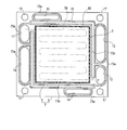
- FIG. 3 is a view of the MEA member viewed from the main surface on the cathode side
- FIG. 4 is a view of the MEA member viewed from the main surface on the anode side
- FIG. 5 is a sectional view taken along line VV in FIG.
- the MEA member 7 is a pair of electrodes 3 of the anode 3 and the cathode 4 stacked on the main surfaces of both the polymer electrolyte membrane 2 and the polymer electrolyte membrane 2 except for the peripheral portion.
- 4 and a plate-like frame 6 in which the electrodes of the MEA 5 are disposed in the frame by sandwiching the peripheral portion of the polymer electrolyte membrane 2.
- the anode 3 and the cathode 4 respectively have catalyst layers 3a and 4a in contact with the polymer electrolyte membrane 2 and gas diffusion layers 3b and 4b covering the catalyst layers 3a and 4a.
- the configuration of the MEA member 7 will be described in detail later.
- Bolt holes 17, 27, 37, fuel gas supply manifold holes 11, 21, 31, 31, fuel gas discharge manifold holes 12, 22, 32 are provided in the frame 6 of the MEA member 7, the anode side separator 9, and the cathode side separator 8.
- Oxidant gas supply manifold holes 13, 23, 33, oxidant gas discharge manifold holes 14, 24, 34, cooling water supply manifold holes 15, 25, 35, and cooling water discharge manifold holes 16, 26, 36, respectively. Are provided so as to penetrate the main surface thereof.
- the fuel gas supply manifold holes 11, 21, and 31 and the fuel gas discharge manifold holes 12, 22, and 32 are connected in the state of the cell stack 99 to form the fuel gas supply manifold 91 and the fuel gas discharge manifold 92, respectively. There is.
- the oxidant gas supply manifold holes 13, 23 and 33 and the oxidant gas discharge manifold holes 14, 24 and 34 are connected in the state of the cell stack 99, and respectively the oxidant gas supply manifold 93 and the oxidant gas discharge manifold 94 Form.
- the cooling water supply manifold holes 15, 25, 35 and the cooling water discharge manifold holes 16, 26, 36 are connected in a state of the cell stack 99 to form the cooling water supply manifold 95 and the cooling water discharge manifold 96, respectively. There is.
- a surface of the anode side separator 9 in contact with the gas diffusion layer 3b of the anode 3 of the MEA 5 is connected to the fuel gas flow channel groove 28 so as to connect the fuel gas supply manifold hole 21 and the fuel gas discharge manifold hole 12.
- the fuel gas flow channel 28 is formed in a serpentine shape over substantially the entire surface where the MEA 5 of the anode side separator 9 abuts.
- the fuel gas flow channel 28 connects the fuel gas supply manifold hole 21 and the fuel gas discharge manifold hole 22 between the MEA member 7 and the anode side separator 9 of the unit cells 10 in a stacked state.
- a passage 98 is formed.
- the oxidant gas supply manifold hole 33 and the oxidant gas discharge manifold hole 34 are connected to connect A gas flow channel 38 is provided.
- the oxidant gas flow channel 38 is formed in a serpentine shape over substantially the entire surface of the cathode side separator 8 in contact with the MEA 5.
- the oxidant gas flow passage groove 38 connects the oxidant gas supply manifold hole 33 and the oxidant gas discharge manifold hole 34 between the MEA member 7 and the cathode side separator 8 of the unit cell 10 in the stacked state.
- An oxidant gas flow path 97 is formed.
- the surface of the anode-side separator 9 in contact with the cathode-side separator 8 is serpentine-like so as to connect the cooling water supply manifold hole 25 and the cooling water discharge manifold hole 26.
- the formed cooling water channel groove 29 is provided.
- a cooling water flow passage groove formed in a serpentine shape so as to connect the cooling water supply manifold hole 35 and the cooling water discharge manifold hole 36 on the surface of the cathode side separator 8 in contact with the anode side separator 9. 39 are provided.
- cooling water flow grooves 29 and 39 are arranged to be joined in the cell stack 99, and the cooling water supply manifold holes 25 and 35 and the cooling water discharge manifold holes 26 and 36 are provided between the lamination surfaces of the single cells 10 and 10 each other. And a cooling water flow path connecting the
- the separators 8 and 9 may be any gas-impermeable conductive material, for example, one obtained by cutting a resin-impregnated carbon material into a predetermined shape, or one obtained by molding a mixture of carbon powder and a resin material, Generally used.
- the cell stack 99 is supplied with a fuel gas containing hydrogen.
- the fuel gas is introduced into the fuel gas supply manifold 91 and is further supplied to the anode 3 of the MEA 5 while flowing through the fuel gas flow path 98 of each unit cell 10, and the excess fuel gas is supplied through the fuel gas discharge manifold 92. It is discharged out of the stack 99.
- the cell stack 99 is supplied with an oxidant gas (here, air) containing oxygen.
- the oxidant gas is introduced into the oxidant gas supply manifold 93, and is further supplied to the cathode 4 of the MEA 5 while flowing through the oxidant gas flow path 97 of each unit cell 10.
- the excess oxidant gas is the oxidant gas.
- the cell stack 99 is discharged through the discharge manifold 94.
- the heat generated by the PEFC is collected in the cooling water circulating in the order of the cooling water tank 85, the cooling water supply manifold 95 of the cell stack 99, the cooling water flow path between the unit cells 10 and 10, and the cooling water discharge manifold 96. Be done.
- a heat exchanger 86 is provided in the circulating path of the cooling water, and the heat recovered in the cooling water is transferred to the water circulating through the heat exchanger 86 and the hot water storage tank 87 and is transferred to the hot water storage tank 87. It is stored as hot water.
- the electricity generated by the PEFC is taken out from the electrical output terminal 81a of the current collector plate 81 by the output control device 88 and supplied to the power load.
- FIG. 3 is a view of the MEA member viewed from the main surface on the cathode side
- FIG. 4 is a view of the MEA member viewed from the main surface on the anode side
- FIG. 5 is a cross-sectional view taken along line VV in FIG. It is sectional drawing which shows the structure of.
- the MEA 5 includes a polymer electrolyte membrane 2, an anode 3 stacked on the first main surface of the polymer electrolyte membrane 2, and a cathode 4 stacked on the second main surface.
- the polymer electrolyte membrane 2 is substantially quadrilateral
- the electrodes 3 and 4 of the anode 3 and the cathode 4 are also substantially quadrilateral
- the polymer electrolyte membrane 2 leaves peripheral portions of four sides. It is covered with the electrodes 3 and 4.
- the polymer electrolyte membrane 2 is an ion exchange membrane which is considered to selectively permeate hydrogen ions.
- a perfluorocarbon sulfonic acid membrane exemplified by NAFION exemplified by NAFION (NAFION is a registered trademark of EI du Pont de Nemours and Company) is preferable.
- the anode 3 includes a catalyst layer 3a mainly composed of carbon powder carrying a platinum-ruthenium alloy catalyst and a gas diffusion layer 3b having both air permeability and electron conductivity.
- the cathode 4 is provided with a catalyst layer 4a mainly composed of carbon powder carrying a platinum catalyst, and a gas diffusion layer 3b having both air permeability and electron conductivity.
- the MEA 5 having such a configuration is manufactured by forming the catalyst layers 3a and 4a and the gas diffusion layers 3b and 4b sequentially on the polymer electrolyte membrane 2 by a method such as coating or transfer.
- the peripheral portion of the MEA 5 may be in a state in which the polymer electrolyte membrane 2 is exposed as it is, but in order to protect and reinforce the thin film polymer electrolyte membrane 2, a resin or elastomer is used.
- the protective film 71 can be provided as a polymer electrolyte membrane protective member. When the protective film 71 is provided in the MEA 5, the protective film 71, not the polymer electrolyte membrane 2, appears on the surface of the peripheral portion of the MEA 5.
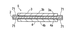
- FIG. 7 is a cross-sectional view showing the structure of alternative embodiment 1 of MEA
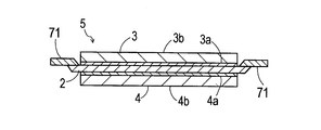
- FIG. 8 is a cross-sectional view showing the structure of alternative embodiment 2 of MEA
- FIG. 9 is a cross-sectional view showing the structure of alternative embodiment 3 of MEA.
- the protective film 71 when viewed from the thickness direction of the polymer electrolyte membrane 2, the protective film 71 partially overlaps with the peripheral portions of the electrodes 3 and 4, and both of the polymer electrolyte membrane 2 It can be provided to cover the peripheral portion of the main surface.
- the protective film 71 has a substantially rectangular frame shape and is in a form joined to a polymer electrolyte film exposed between the stacked electrodes 3 and 4. It is also good.
- Such a protective film 71 can be produced, for example, by applying the technique described in Japanese Patent Application Laid-Open No. 5-234606.
- the protective film 71 may be in a form that completely covers the peripheral edge portion of the polymer electrolyte membrane 2 which is not covered by the electrodes 3 and 4.
- Such a protective film 71 can be produced, for example, by applying the technique described in Japanese Patent Application Publication No. 7-501417.
- the frame 6 has a function as a gasket seal which seals the MEA 5 between the separators 8 and 9 and a function as a holding member which makes the MEA 5 easy to handle.
- the frame 6 is a thin plate-like substantially rectangular frame having a substantially rectangular opening 60 at substantially the center of the surface, and the MEA 5 is disposed in the opening 60 (within the frame).
- the frame 6 has a two-part structure in the thickness direction of a first surface material 6 a in contact with the anode side separator 9 and a second surface material 6 b in contact with the cathode side separator 8. Then, the first surface material 6 a and the second surface material 6 b sandwich and hold the peripheral portion of the MEA 5 in a state in which the electrodes 3 and 4 are exposed to the opening 60 of the frame 6. The MEA 5 is held.
- the frame 6 is made of a thermoplastic resin.
- gaskets 73 are provided on the main surfaces on both sides of the frame 6.
- the gasket 73 is disposed on the frame 6 so that the reaction gas of the fuel gas and the oxidant gas and the cooling water do not leak from the predetermined flow path.
- the gasket 73 is provided with each manifold hole (fuel gas supply manifold hole 11, fuel gas discharge manifold hole 12, oxidant gas supply manifold hole 13, oxidant gas discharge manifold)
- the manifold hole gasket 73a formed at a position surrounding the hole 14, the cooling water supply manifold hole 15, and the cooling water discharge manifold hole 16) and the electrodes 3 and 4 of the MEA 5 in the inner peripheral portion of the frame 6
- An electrode gasket 73b formed at a position is provided.
- the manifold hole gasket 73a and the electrode gasket 73b are formed in a straight line so as to eliminate the break of the gasket, but depending on the function and position of the gasket, the manifold hole gasket 73a And the electrode gasket 73b.
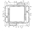
- the frame 6 has a separation part for separating the MEA 5 from the frame 6, in this case, a broken line in the form of a broken line 50 for dividing the frame 6 into two or more parts.
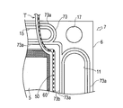
- FIG. 10 is a view of the MEA member for explaining the cut lines provided in the frame as viewed from the main surface on the cathode side
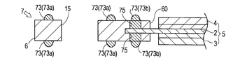
- FIG. 11 is a partial view of the MEA member for explaining the cut lines provided in the frame
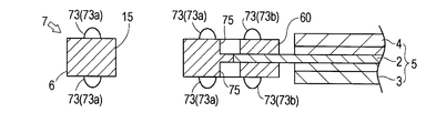
- FIG. FIG. 13 is a cross-sectional view taken along the line XIII-XIII in FIG. 11, and
- FIG. 14 is a view showing a state in which a part of the frame is cut away using a cut line.
- the "cutting lines 50" provided to the frame 6 in the present invention refer to a plurality of cuts provided at predetermined intervals so as to draw a line.
- the "cut” refers to a hole provided on the surface of the frame, and the hole may be a recess or a through hole.
- the shape of each cut is not particularly limited, and may be, for example, rectangular or rhombus as viewed from the main surface side of MEA member 7 (the thickness direction of polymer electrolyte membrane 2). It may be circular. It is desirable that one end or both ends of the cut line 50 be connected to the inner peripheral edge or the outer peripheral edge of the frame 6. If such a piercing line 50 is used, for example, as shown in FIG.
- a part (T) of the frame 6 can be trimmed.
- one end or both ends of the tear line 50 does not necessarily need to be connected to the inner peripheral edge or the outer peripheral edge of the frame 6, and part of the frame 6 may be broken by tearing a part of the frame 6 using the tear line 50. I wish I could destroy it. That is, although it is desirable that the tearing line 50 is a line which can divide the frame 6 into two or more parts, it is not always necessary, as long as it is a line which can partially destroy the frame 6.
- the tear line 50 is provided at a portion of the frame 6 where the frame 6 and the peripheral portion of the MEA 5 overlap when viewed from the main surface side of the MEA member 7 (the thickness direction of the polymer electrolyte membrane 2). Note that the perforation lines 50 shown in FIGS. 10 and 11 are provided at positions overlapping with the electrode gasket 73 b when viewed from the main surface side of the MEA member 7.
- the plurality of cuts 75, 75,... Forming the cutting line 50 have a depth such that the peripheral portion of the MEA 5 sandwiched by the frame 6 appears at the bottom. . That is, the cuts 75, 75, ... reach the peripheral portion of the MEA 5.
- the polymer electrolyte membrane 2 is exposed at the periphery of the MEA 5
- the polymer electrolyte membrane 2 appears at the bottom of the cut 75 and the periphery of the MEA 5 is covered with the protective film 71.
- the protective film 71 what appears at the bottom of the cut 75 is the protective film 71.
- the plurality of cuts 75, 75,... Forming the cutting line 50 are main surfaces of both the first main surface and the second main surface of the frame 6. It is opened in the surface and is opposed with the MEA 5 interposed therebetween.
- the cutting lines 50 do not necessarily have to be provided on both the first main surface and the second main surface of the frame 6 and may be only one.
- the cut 75 forming the cutting line 50 is opened only to the first main surface side of the frame 6 or only to the second main surface side of the frame 6. It may be done.
- the cuts 75 forming the cutting line 50 do not necessarily have to be opposed via the MEA 5.
- the cuts 75 may be alternately and continuously provided on the first main surface side of the frame 6 and the second main surface side.
- the MEA 5 of the frame 6 It is possible to cut out or destroy a part holding the peripheral part.
- the force holding the MEA 5 acting on the MEA 5 from the frame 6 is partially or totally released, so It becomes easy to take out from the frame 6. Therefore, the MEA 5 and the frame 6 can be easily separated without damaging the MEA 5 without using a special tool.
- the cutout line 50 is formed on the outer peripheral side including the portion of the frame 6 where the electrode gasket 73 b is formed, and the manifold hole gasket 73 a is formed. It is desirable to provide it on the inner peripheral side than this including the portion.
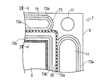
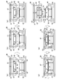
- FIG. 15 is a partial view of an MEA member for explaining a modification 1 of the cutout line provided in the frame
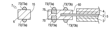
- FIG. 16 is a cross-sectional view taken along the XVI-XVI arrow in FIG. 18 is a cross-sectional view taken along the line XVIII-XVIII in FIG.
- the perforations 50 shown in FIGS. 15 and 16 are provided in a portion of the frame 6 sandwiched by the manifold hole gasket 73 a and the electrode gasket 73 b when viewed from the main surface side of the MEA member 7.
- the cutting lines 50 are provided in portions of the frame 6 overlapping the manifold hole gaskets 73 a when viewed from the main surface side of the MEA member 7.
- FIG. 19 is a view of an MEA member seen from a main surface on the cathode side for explaining a third modification of the perforations provided in the frame.
- the tear line 50 may be a line connecting the inner peripheral edge and the outer peripheral edge of the frame 6.
- FIG. 20 is a view for explaining the molding process of the frame.
- a mold 58 for molding the frame 6 includes a fixed mold 62 and a movable mold 61 attached to a molding machine (not shown) and capable of advancing and retracting with respect to the fixed mold 62.
- the movable mold 61 is provided with a guide pin 63
- the fixed mold 62 is provided with a guide pin bush 64
- the guide pin 63 is inserted into and guided by the guide pin bush 64 so that the movable mold 61 is fixed. 62 can move back and forth in a predetermined direction.
- the fixed mold 62 is attached with a cavity plate 66 to which a first mold (not shown) having a molding surface 66a of the molded product is fixed, and the movable mold 61 is a second molding mold having a molding surface 65a of the molding ( The core plate 65 to which the illustration is omitted is fixed. And, by combining the cavity plate 66 and the core plate 65, a cavity surrounded by the formation surfaces 66a and 65a is formed between them. Further, the core plate 65 is provided with a runner 67 and a gate 68 which are flow paths through which the material resin flows. In addition, the fixed mold 62 is provided with an ejector pin 59 for taking out a molded product on the molding surface of the cavity plate 66.
- the first surface material 6a of the frame 6 is molded in advance.
- the first surface material 6a is not limited to injection molding, and may be formed by another molding method.
- the first surface material 6 a is placed at a predetermined position on the shaped surface 66 a of the cavity plate 66.
- the MEA 5 is placed on the first surface material 6a so that the peripheral portion of the MEA 5 contacts the first surface material 6a placed on the shaped surface 66a of the cavity plate 66. It is placed.
- the movable mold 61 moves in the direction in which the movable mold 61 approaches the fixed mold 62, and mold clamping is performed.
- core plate 65 is pressed against cavity plate 66 to form a cavity between cavity plate 66 and core plate 65.
- the peripheral portion of the MEA 5 held in the cavity in the state of being clamped as described above is sandwiched between the pressing portion 69 formed on the shaped surface 65 a of the core plate 65 and the shaped surface 66 a of the cavity plate 66. Is fixed.
- the pressing portion 69 is a convex portion provided to form a plurality of cuts 75, 75,... In this state, high-temperature and high-pressure material resin is injected into the cavity, but a part of the peripheral portion of the MEA 5 in the cavity is in a state of being pressed and fixed by the pressing portion 69 The rise is suppressed.
- the material resin is injected into the runner 67 in the mold 58 that is clamped.
- the material resin passes through the runner 67, passes through the gate 68, flows into the cavity, and the cavity is filled with the material resin.
- the movable mold 61 is moved away from the fixed mold 62 in a direction away from the fixed mold 62, and the mold is opened. Is removed from the mold 58.
- the MEA member 7 in a state in which the peripheral portion of the MEA 5 is held between the first surface material 6 a and the second surface material 6 b of the frame 6 is formed.
- a hole penetrating to the surface of the MEA 5 is formed in the second surface material 6 b as a mark of the pressing portion 69 of the shaped surface 65 a. This hole will be a cut 75 forming a tear line 50.
- an MEA member (a framed membrane-electrode assembly) according to a second embodiment of the present invention will be described with reference to FIGS.
- the PEFC polymer electrolyte fuel cell
- the PEFC polymer electrolyte fuel cell
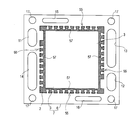
- FIG. 21 is a view of the MEA member according to Embodiment 2 as viewed from the main surface on the cathode side
- FIG. 22 is a view of the MEA member according to Embodiment 2 as viewed from the main surface on the anode side
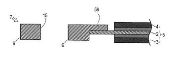
- FIG. 24 is an XXIV-XXIV arrow end cross-sectional view in FIG.
- the gasket 73 illustrated in FIG. 10 and the like is omitted.
- the MEA member 7 according to the second embodiment includes the MEA 5, the frame 6, and the separation unit, and in this respect, is common to the MEA member according to the first embodiment. .
- the MEA member 7 according to the first embodiment has the separation portion 50 as the separation portion
- the MEA member 7 according to the second embodiment is configured in that both the separation portion is the partial pinching portion 55 Is different.
- the configuration of the separation portion (partial pinching portion 55) which is a difference from the first embodiment will be described.
- the separation portion is the partial holding portion 55.
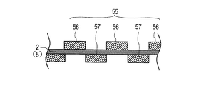
- the partial holding portion 55 is formed on the inner peripheral portion of the frame 6 and is configured to partially hold the peripheral portion of the MEA 5.
- the term "partially pinching” as used herein is intended to exclude the case of pinching the entire surface of the portion, and is pinched with the portion pinched when viewed partially. When there is a mixture with non-parts, this corresponds to "partially holding".
- the partial pinching portion 55 is mainly configured of a first projecting piece 56 shown in FIG. 21 and a second projecting piece 57 shown in FIG.
- first projecting pieces 56 are formed over the entire circumference of the inner peripheral portion of the frame 6.
- Each first projecting piece 56 projects inward from the inner peripheral portion of the frame 6 and is continuously formed at a predetermined interval.
- the first projecting piece 56 has a T-like shape in which the width of the distal end portion is larger than the width of the proximal end portion, and the proximal end coincides with the outer edge of the MEA 5 (see FIG. 23).
- the 1st protrusion piece 56 is located in the cathode side (paper surface upper side of FIG. 24) of MEA of a frame.
- a plurality of second protruding pieces 57 are also formed over the entire circumference of the inner peripheral portion of the frame 6.
- Each second projecting piece 57 projects inward from the inner peripheral portion of the frame 6 and is continuously formed at a predetermined interval.
- the second projecting piece 57 has a T-like shape in which the width of the distal end portion is larger than the width of the proximal end portion, and is configured such that the proximal end coincides with the outer edge of the MEA 5.
- the 2nd protrusion piece 57 is located in the anode side (paper surface lower side of FIG. 24) of MEA5 of the frame 6. As shown in FIG.
- the 1st protrusion piece 56 and the 2nd protrusion piece 57 are arrange
- the MEA 5 is in contact with the first projecting piece 56 or the second projecting piece 57 in the "whole surface" of the peripheral portion. Do not mean. That is, the peripheral portion of the MEA 5 is “partially” held by the first projecting piece 56 and the second projecting piece 57. In FIG. 24, the polymer electrolyte membrane 2 of the MEA 5 is directly held by the first projecting piece 56 and the second projecting piece 57. However, as shown in FIGS. 7 to 9, the peripheral portion of the MEA 5 In the case where the protective film 71 is covered, the first projecting piece 56 and the second projecting piece 57 sandwich the MEA 5 via the protective film 71.
- the sandwiching of the MEA 5 by the first projecting piece 56 and the second projecting piece 57 is partial, but overall, the MEA 5 has the entire periphery of the peripheral portion. Since the MEA 5 is sandwiched, the movement of the MEA 5 in the thickness direction is surely limited. On the other hand, since the MEA 5 is partially pinched, the area of the portion in which the MAE 5 is pinched is smaller than in the case where the entire peripheral portion of the MEA 5 is pinched, and perpendicular to the thickness direction The MEA 5 can be easily pulled out in the direction. In particular, when the first projecting pieces 56 and the second projecting pieces 57 are alternately disposed, the effect is remarkable. Therefore, for example, when the MEA 5 is to be pulled out from the frame 6 (partial holding portion 55) while bending the entire MEA member 7, the MEA 5 can be easily removed from the frame 6.
- the above is the configuration of the MEA member 7 according to the second embodiment, in particular, the separation portion (partial pinching portion 55).
- the MEA member 7 according to the second embodiment can be manufactured by the injection molding process shown in FIG. 20 by adopting the two-divided structure similarly to the MEA member 7 according to the first embodiment. That is, the first surface material 6a corresponding to the anode side portion (including the second projecting piece 57) of the frame 6 is manufactured in advance (see FIG. 20 (b)), and the MEA 5 is placed thereon. (See FIG. 20 (c)) Further, a second surface material 6b corresponding to the cathode side portion (including the first projecting piece 56) of the frame 6 is formed thereon by injection molding (FIG.
- the entire inner peripheral portion refers to the first projecting piece 56, a portion visible from between the first projecting piece 56 and the first projecting piece 56 in the peripheral portion of the MEA 5, the second projecting piece 57, and the MEA 5 This is a region including a portion visible from between the second projecting piece 57 and the second projecting piece 57 in the peripheral portion.
- the thin film 72 can close a gap generated between the MEA 5 and the frame 6, and the first projecting piece 56 and the second projecting piece 57 may be broken during use, or the MEA 5 may be shaken in the frame 6. You can prevent.
- the thin film 72 when removing the MEA 5 from the frame 6, it is necessary to remove the thin film 72 first, but the thin film 72 can be easily peeled off, which does not cause a heavy burden in operation.
- first projecting piece 56 and the second projecting piece 57 are T-shaped
- the shapes of the first projecting piece 56 and the second projecting piece 57 are not limited thereto.
- each may be formed in a rectangular shape having the same width from the proximal end to the distal end.
- the material can be reduced as compared with the case where the first projecting piece 56 and the second projecting piece 57 are rectangular.
- the first projecting pieces 56 and the second projecting pieces 57 are alternately arranged in the circumferential direction of the frame 6
- the MEA member 7 does not necessarily have to be alternately arranged.
- the first projection 56 and the second projection 57 may be configured to overlap in whole or in part.
- the proximal ends of the first projecting piece 56 and the second projecting piece 57 match the outer edge of the MEA 5, but the proximal ends of the first projecting piece 56 and the second projecting piece 57 are the outer edge of the MEA 5
- You may comprise so that it may be located inside rather than. That is, the peripheral portion of the MEA 5 may be configured to bite into the inside of the frame 6 more than in the case shown in FIG. According to this configuration, it is possible to prevent the formation of a gap between the MEA 5 and the frame 6.
- Embodiment 1 and Embodiment 2 which concern on this invention were demonstrated with reference to figures, a specific structure is not restricted to these embodiments, It is the range which does not deviate from the summary of this invention. Even if there is a change in design, etc., it is included in the present invention.
- the present invention provides an MEA member comprising a polymer electrolyte membrane-electrode assembly (MEA) and a frame, and a structure capable of separating and recovering MEA from the frame in a solid polymer fuel cell comprising the MEA member. It can be widely applied as an MEA member having.
- MEA polymer electrolyte membrane-electrode assembly
Landscapes
- Life Sciences & Earth Sciences (AREA)
- Sustainable Development (AREA)
- Engineering & Computer Science (AREA)
- Manufacturing & Machinery (AREA)
- Sustainable Energy (AREA)
- Chemical & Material Sciences (AREA)
- Chemical Kinetics & Catalysis (AREA)
- Electrochemistry (AREA)
- General Chemical & Material Sciences (AREA)
- Fuel Cell (AREA)
Abstract
Description
本発明の実施の形態1に係る枠付き膜-電極接合体、及び固体高分子形燃料電池について説明する。以下、膜-電極接合体を「MEA」と、枠付き膜-電極接合体を「MEA部材」と、固体高分子形燃料電池を「PEFC」と記載する。
まず、PEFCの構成を説明する。図1は本発明の実施の形態1に係る固体高分子形燃料電池を一部分解してその構造を模式的に示す斜視図、図2は固体高分子形燃料電池を一部分解してセパレータ間に設けられた冷却水供給流路の構造を示す斜視図、図26は固体高分子形燃料電池を用いた発電システムの概要を示す図である。
ここで、セルスタック99の基本構成単位となる単セル10の構造について説明する。単セル10は、MEA部材7と、MEA部材7を挟み込むようにその両方の主面に積層されたアノード側セパレータ9及びカソード側セパレータ8の一対のセパレータとを備えている。
ここで、上記構成のPEFCの発電時の動作について説明する。図26に示すように、セルスタック99には、水素を含む燃料ガスが供給される。燃料ガスは、燃料ガス供給マニホールド91に導入され、さらに、各単セル10の燃料ガス流路98を流れるうちにMEA5のアノード3に供給され、余剰の燃料ガスは、燃料ガス排出マニホールド92を通じてセルスタック99の外へ排出される。また、セルスタック99には、酸素を含有する酸化剤ガス(ここでは、空気)が供給される。酸化剤ガスは、酸化剤ガス供給マニホールド93に導入され、さらに、各単セル10の酸化剤ガス流路97を流れるうちにMEA5のカソード4に供給され、余剰の酸化剤ガスは、酸化剤ガス排出マニホールド94を通じてセルスタック99の外へ排出される。このようにして、MEA5に燃料ガスと酸化剤ガスとが供給されると、これらが電極3,4で電気化学的に反応して、電気と熱と水とが発生する。
ここで、MEA部材7の構成について、詳細に説明する。図3はMEA部材をカソード側の主面から見た図、図4はMEA部材をアノード側の主面から見た図、図5は図3におけるV-V矢視断面図、図6はMEAの構造を示す断面図である。
次に、MEA5に切取線50を有する枠体6を射出成形により成形する方法について、説明する。図20は枠体の成形工程を説明する図である。
次に、図21~24を参照しながら、本発明の実施の形態2に係るMEA部材(枠付き膜-電極接合体)について説明する。なお、実施の形態2に係るPEFC(固体高分子形燃料電池)については、MEA部材以外は実施の形態1に係るPEFCと同じ構成であるため、実施の形態2に係るPEFCについての説明は省略する。図21は実施の形態2に係るMEA部材をカソード側の主面から見た図、図22は実施の形態2に係るMEA部材をアノード側の主面から見た図、図23は図21におけるXXIII-XXIII矢視端面断面図、図24は図21におけるXXIV-XXIV矢視端面断面図である。なお、これらの図では、図10等で図示していたガスケット73は省略されている。
3 アノード
4 カソード
5 MEA(膜-電極接合体)
6 枠体
7 MEA部材
8 カソード側セパレータ
9 アノード側セパレータ
10 単セル
11 燃料ガス供給マニホールド孔
12 燃料ガス排出マニホールド孔
13 酸化剤ガス供給マニホールド孔
14 酸化剤ガス排出マニホールド孔
15 冷却水供給マニホールド孔
16 冷却水排出マニホールド孔
17 ボルト孔
50 切取線
55 部分狭持部
56 第1突出片
57 第2突出片
72 薄膜
73 ガスケット
73a マニホールド孔用ガスケット
73b 電極用ガスケット
75 切れ目
Claims (13)
- 高分子電解質膜及び該高分子電解質膜の主面の両側に配置された一対の電極を有するMEAと、
前記MEAの主面の周縁部を両側から挟み込んで保持することによって枠内に前記MEAが配設された樹脂製の板状の枠体と、
前記枠体から前記MEAを分離するための分離部とを、有し、
前記分離部は、前記枠体に設けられた、前記枠体を2つ以上の部分に分割するための破線状の切取線であるか、又は、前記MEAの周縁部を部分的に狭持するよう構成された前記枠体の内周部分に位置する部分狭持部である、
MEA部材。 - 前記分離部が前記切取線であり、
前記枠体は、前記高分子電解質膜の厚み方向に貫通するマニホールド孔と、前記マニホールド孔を囲むように前記枠体上に配置されたマニホールド孔用ガスケットと、前記電極を囲むように前記枠体上に配置された電極用ガスケットとを、有し、
前記切取線は、前記高分子電解質膜の厚み方向から見て、前記枠体の前記電極用ガスケットが形成された部分を含めてこれよりも外周側で、且つ、前記マニホールド孔用ガスケットが形成された部分を含めてこれよりも内周側に、設けられている、
請求項1に記載のMEA部材。 - 前記分離部が前記切取線であり、
前記切取線は、前記高分子電解質膜の厚み方向から見て、前記枠体の前記枠体と前記MEAの周縁部とが重なっている部分に設けられ、前記MEAの周縁部にまで達する複数の切れ目で形成されている、
請求項1又は請求項2に記載のMEA部材。 - 前記複数の切れ目の少なくとも一部は、前記電極用ガスケット又は前記マニホールド孔用ガスケットにより埋められている、
請求項3に記載のMEA部材。 - 前記複数の切れ目は、前記枠体の第一の主面と第二の主面とに交互に連続して設けられている、
請求項3又は請求項4に記載のMEA部材。 - 前記複数の切れ目は、前記枠体の第一の主面及び第二の主面のうちいずれか一方に設けられている、
請求項3又は請求項4に記載のMEA部材。 - 前記複数の切れ目は、前記枠体の第一の主面及び第二の主面の両側に、前記MEAの周縁部を間に挟んで対向して設けられている、
請求項3又は請求項4に記載のMEA部材。 - 前記MEAの周縁部に前記高分子電解質膜が露出しており、
前記MEAの周縁部において、前記枠体と前記高分子電解質膜とが接触している、
請求項1に記載のMEA部材。 - 前記高分子電解質膜の周縁部に膜補強部材が設けられており、
前記MEAの周縁部において、前記枠体と前記膜補強部材とが接触している、
請求項1に記載のMEA部材。 - 前記分離部は前記部分狭持部であって、
前記部分狭持部は、前記枠体の内周部分から部分的に内方へ突出する第1突出片と、前記枠体の内周部分から部分的に内方へ突出する第2突出片とを有し、
前記MEAの周縁部が、前記第1突出片と前記第2突出片とによって狭持されている、請求項1に記載のMEA部材。 - 前記第1突出片は所定の間隔をおいて連続的に複数形成されるとともに、前記第2突出片は所定の間隔をおいて連続的に複数形成され、前記第1突出片と前記第2突出片とは前記枠体の周方向において交互に配設されている、請求項10に記載のMEA部材。
- 前記枠体の少なくとも一方の主面側において、その内周部分の全体が薄膜で覆われている、請求項10又は11に記載のMEA部材。
- 請求項1~請求項12のいずれか一項に記載のMEA部材と、
前記MEA部材を挟み込むように該MEA部材の両面に積層され、前記電極と当接する領域に反応ガス流路が設けられた一対のセパレータとを、
備えた、固体高分子形燃料電池。
Priority Applications (4)
| Application Number | Priority Date | Filing Date | Title |
|---|---|---|---|
| CN2009801000538A CN101790811B (zh) | 2008-05-30 | 2009-05-28 | Mea部件和固体高分子型燃料电池 |
| US12/674,843 US8298697B2 (en) | 2008-05-30 | 2009-05-28 | MEA member and polymer electrolyte fuel cell |
| JP2009548521A JP4585036B2 (ja) | 2008-05-30 | 2009-05-28 | Mea部材及び固体高分子形燃料電池 |
| EP09754449.8A EP2293371B1 (en) | 2008-05-30 | 2009-05-28 | Mea member and polymer electrolyte fuel cell |
Applications Claiming Priority (2)
| Application Number | Priority Date | Filing Date | Title |
|---|---|---|---|
| JP2008-142455 | 2008-05-30 | ||
| JP2008142455 | 2008-05-30 |
Publications (1)
| Publication Number | Publication Date |
|---|---|
| WO2009144940A1 true WO2009144940A1 (ja) | 2009-12-03 |
Family
ID=41376830
Family Applications (1)
| Application Number | Title | Priority Date | Filing Date |
|---|---|---|---|
| PCT/JP2009/002356 Ceased WO2009144940A1 (ja) | 2008-05-30 | 2009-05-28 | Mea部材及び固体高分子形燃料電池 |
Country Status (5)
| Country | Link |
|---|---|
| US (1) | US8298697B2 (ja) |
| EP (1) | EP2293371B1 (ja) |
| JP (1) | JP4585036B2 (ja) |
| CN (1) | CN101790811B (ja) |
| WO (1) | WO2009144940A1 (ja) |
Cited By (2)
| Publication number | Priority date | Publication date | Assignee | Title |
|---|---|---|---|---|
| US20120171592A1 (en) * | 2010-12-31 | 2012-07-05 | Samsung Electronics Co., Ltd. | Unit cell of fuel cell stack and fuel cell stack having the unit cell |
| EP3101719A1 (en) | 2015-06-02 | 2016-12-07 | Panasonic Intellectual Property Management Co., Ltd. | Assembly, fuel cell using same, and method of disassembling same |
Families Citing this family (9)
| Publication number | Priority date | Publication date | Assignee | Title |
|---|---|---|---|---|
| JP5786419B2 (ja) * | 2011-04-05 | 2015-09-30 | 日産自動車株式会社 | 燃料電池セル |
| US10276879B2 (en) * | 2012-06-18 | 2019-04-30 | Nissan Motor Co., Ltd. | Fuel cell |
| US9963795B2 (en) | 2013-04-30 | 2018-05-08 | Asahi Kasei Kabushiki Kaisha | Gasket and electrolyser |
| KR101481354B1 (ko) * | 2013-12-30 | 2015-01-09 | 현대자동차주식회사 | 연료전지 mea |
| JP6859823B2 (ja) * | 2017-04-17 | 2021-04-14 | トヨタ自動車株式会社 | 燃料電池セル |
| KR102602415B1 (ko) * | 2018-09-04 | 2023-11-14 | 현대자동차주식회사 | 전극막접합체 |
| KR102695978B1 (ko) | 2019-09-20 | 2024-08-19 | 주식회사 엘지에너지솔루션 | 자성체가 형성된 분리막을 포함하는 전지셀 및 이를 이용한 내부 단락에 따른 전지셀의 안전성 평가방법 |
| CN211125829U (zh) * | 2020-01-03 | 2020-07-28 | 宁波索福人能源技术有限公司 | 一种固体氧化物燃料电池堆 |
| DE102020207601A1 (de) * | 2020-06-19 | 2021-12-23 | Robert Bosch Gesellschaft mit beschränkter Haftung | Verfahren zur Herstellung einer Brennstoffzelle, Brennstoffzelle |
Citations (7)
| Publication number | Priority date | Publication date | Assignee | Title |
|---|---|---|---|---|
| JP2002093434A (ja) * | 2000-09-18 | 2002-03-29 | Honda Motor Co Ltd | 電解質層・電極接合体および燃料電池 |
| JP2005209479A (ja) * | 2004-01-22 | 2005-08-04 | Aisin Seiki Co Ltd | 燃料電池用膜電極接合体及びその製造方法、燃料電池 |
| WO2006040994A1 (ja) * | 2004-10-08 | 2006-04-20 | Matsushita Electric Industrial Co., Ltd. | Mea-ガスケット接合体及びそれを用いた高分子電解質形燃料電池 |
| JP2006120520A (ja) * | 2004-10-22 | 2006-05-11 | Nissan Motor Co Ltd | 燃料電池 |
| JP2006310288A (ja) * | 2005-04-01 | 2006-11-09 | Matsushita Electric Ind Co Ltd | Mea、meaの製造方法及び高分子電解質形燃料電池 |
| JP2008235159A (ja) * | 2007-03-23 | 2008-10-02 | Toyota Motor Corp | 燃料電池 |
| WO2009047908A1 (ja) * | 2007-10-12 | 2009-04-16 | Panasonic Corporation | 高分子電解質型燃料電池用の電極-膜-枠接合体およびその製造方法、並びに高分子電解質型燃料電池 |
Family Cites Families (6)
| Publication number | Priority date | Publication date | Assignee | Title |
|---|---|---|---|---|
| DE69204834T2 (de) | 1991-06-04 | 1996-04-04 | Ballard Power Systems | Gegliederte membranelektrodenanordnung für elektrochemische brennstoffzelle. |
| CN1536698B (zh) * | 2003-04-02 | 2010-12-15 | 松下电器产业株式会社 | 燃料电池用电解质膜结构、mea结构及燃料电池 |
| JP4887600B2 (ja) * | 2003-11-10 | 2012-02-29 | トヨタ自動車株式会社 | 燃料電池、その分解方法およびそのセパレータ |
| KR101270856B1 (ko) * | 2005-04-01 | 2013-06-05 | 파나소닉 주식회사 | Mea, mea의 제조방법 및 고분자 전해질형 연료 전지 |
| JP2007115445A (ja) * | 2005-10-18 | 2007-05-10 | Toyota Motor Corp | 燃料電池 |
| CN101542798B (zh) * | 2007-03-30 | 2012-10-24 | 松下电器产业株式会社 | 高分子电解质型燃料电池及电极-膜-框接合体的制造方法 |
-
2009
- 2009-05-28 CN CN2009801000538A patent/CN101790811B/zh not_active Expired - Fee Related
- 2009-05-28 EP EP09754449.8A patent/EP2293371B1/en not_active Not-in-force
- 2009-05-28 US US12/674,843 patent/US8298697B2/en not_active Expired - Fee Related
- 2009-05-28 JP JP2009548521A patent/JP4585036B2/ja not_active Expired - Fee Related
- 2009-05-28 WO PCT/JP2009/002356 patent/WO2009144940A1/ja not_active Ceased
Patent Citations (7)
| Publication number | Priority date | Publication date | Assignee | Title |
|---|---|---|---|---|
| JP2002093434A (ja) * | 2000-09-18 | 2002-03-29 | Honda Motor Co Ltd | 電解質層・電極接合体および燃料電池 |
| JP2005209479A (ja) * | 2004-01-22 | 2005-08-04 | Aisin Seiki Co Ltd | 燃料電池用膜電極接合体及びその製造方法、燃料電池 |
| WO2006040994A1 (ja) * | 2004-10-08 | 2006-04-20 | Matsushita Electric Industrial Co., Ltd. | Mea-ガスケット接合体及びそれを用いた高分子電解質形燃料電池 |
| JP2006120520A (ja) * | 2004-10-22 | 2006-05-11 | Nissan Motor Co Ltd | 燃料電池 |
| JP2006310288A (ja) * | 2005-04-01 | 2006-11-09 | Matsushita Electric Ind Co Ltd | Mea、meaの製造方法及び高分子電解質形燃料電池 |
| JP2008235159A (ja) * | 2007-03-23 | 2008-10-02 | Toyota Motor Corp | 燃料電池 |
| WO2009047908A1 (ja) * | 2007-10-12 | 2009-04-16 | Panasonic Corporation | 高分子電解質型燃料電池用の電極-膜-枠接合体およびその製造方法、並びに高分子電解質型燃料電池 |
Cited By (3)
| Publication number | Priority date | Publication date | Assignee | Title |
|---|---|---|---|---|
| US20120171592A1 (en) * | 2010-12-31 | 2012-07-05 | Samsung Electronics Co., Ltd. | Unit cell of fuel cell stack and fuel cell stack having the unit cell |
| EP3101719A1 (en) | 2015-06-02 | 2016-12-07 | Panasonic Intellectual Property Management Co., Ltd. | Assembly, fuel cell using same, and method of disassembling same |
| US10637076B2 (en) | 2015-06-02 | 2020-04-28 | Panasonic Intellectual Property Management Co., Ltd. | Assembly, fuel cell using same, and method of disassembling same |
Also Published As
| Publication number | Publication date |
|---|---|
| US8298697B2 (en) | 2012-10-30 |
| EP2293371A4 (en) | 2014-03-12 |
| JP4585036B2 (ja) | 2010-11-24 |
| CN101790811B (zh) | 2013-09-25 |
| US20110143252A1 (en) | 2011-06-16 |
| EP2293371A1 (en) | 2011-03-09 |
| CN101790811A (zh) | 2010-07-28 |
| JPWO2009144940A1 (ja) | 2011-10-06 |
| EP2293371B1 (en) | 2016-05-25 |
Similar Documents
| Publication | Publication Date | Title |
|---|---|---|
| JP4585036B2 (ja) | Mea部材及び固体高分子形燃料電池 | |
| CN1839509B (zh) | 整体燃料电池组合件 | |
| US9490497B2 (en) | Solid polymer electrolyte type fuel cell, and electrolyte membrane-electrode-frame assembly | |
| CA2738180C (en) | Membrane electrode assembly, manufacturing method thereof, and fuel cells | |
| US7531265B2 (en) | Fuel cell | |
| EP2790255B1 (en) | Fuel cell | |
| JP2005276637A (ja) | 燃料電池及び燃料電池用金属セパレータ | |
| JP4843985B2 (ja) | 固体高分子形燃料電池用ガスケット付き電解質膜−電極接合体及びその製造方法 | |
| JP6681537B2 (ja) | 接合体とその接合体を用いた燃料電池、ならびに、その分解方法 | |
| JP2005216700A (ja) | 燃料電池スタック、セパレータ中間体及びセパレータの製造方法 | |
| JP2013175336A (ja) | 燃料電池セルアセンブリの製造方法 | |
| JP2009238495A (ja) | 燃料電池およびこれに用いられる膜−電極−ガス拡散層接合体 | |
| US7681304B2 (en) | Membrane electrode assembly and method of manufacturing a membrane electrode assembly | |
| JP5604404B2 (ja) | 燃料電池 | |
| JP2009151972A (ja) | 燃料電池の発電停止方法、その発電起動方法及び燃料電池システム | |
| JP3622682B2 (ja) | 燃料電池セル及びセルユニット | |
| JP5988104B2 (ja) | 燃料電池 | |
| JP2005129402A (ja) | 燃料電池セルの絶縁構造 | |
| JP2008041456A (ja) | 燃料電池用セパレータの製造方法及び燃料電池用セパレータ | |
| JP2006147256A (ja) | 燃料電池単セル及びその製造方法 | |
| WO2009017208A1 (ja) | 燃料電池、およびその膜-電極接合体の位置合わせ方法 | |
| JP2004146229A (ja) | 燃料電池用基材の製造方法および燃料電池用基材 | |
| JP2009224265A (ja) | 固体高分子形燃料電池用セパレータ及びその製造方法 | |
| JP2008218130A (ja) | 燃料電池 | |
| JP2007220626A (ja) | 燃料電池の単位セル構造 |
Legal Events
| Date | Code | Title | Description |
|---|---|---|---|
| WWE | Wipo information: entry into national phase |
Ref document number: 200980100053.8 Country of ref document: CN |
|
| WWE | Wipo information: entry into national phase |
Ref document number: 2009548521 Country of ref document: JP |
|
| 121 | Ep: the epo has been informed by wipo that ep was designated in this application |
Ref document number: 09754449 Country of ref document: EP Kind code of ref document: A1 |
|
| WWE | Wipo information: entry into national phase |
Ref document number: 2009754449 Country of ref document: EP |
|
| WWE | Wipo information: entry into national phase |
Ref document number: 12674843 Country of ref document: US |
|
| NENP | Non-entry into the national phase |
Ref country code: DE |