WO2009144995A1 - コイルの挿入装置および挿入方法 - Google Patents
コイルの挿入装置および挿入方法 Download PDFInfo
- Publication number
- WO2009144995A1 WO2009144995A1 PCT/JP2009/055256 JP2009055256W WO2009144995A1 WO 2009144995 A1 WO2009144995 A1 WO 2009144995A1 JP 2009055256 W JP2009055256 W JP 2009055256W WO 2009144995 A1 WO2009144995 A1 WO 2009144995A1
- Authority
- WO
- WIPO (PCT)
- Prior art keywords
- delivery wire
- catheter
- coil
- predetermined
- drive unit
- Prior art date
- Legal status (The legal status is an assumption and is not a legal conclusion. Google has not performed a legal analysis and makes no representation as to the accuracy of the status listed.)
- Ceased
Links
Images


Classifications
-
- A—HUMAN NECESSITIES
- A61—MEDICAL OR VETERINARY SCIENCE; HYGIENE
- A61B—DIAGNOSIS; SURGERY; IDENTIFICATION
- A61B17/00—Surgical instruments, devices or methods
- A61B17/12—Surgical instruments, devices or methods for ligaturing or otherwise compressing tubular parts of the body, e.g. blood vessels or umbilical cord
- A61B17/12022—Occluding by internal devices, e.g. balloons or releasable wires
- A61B17/12099—Occluding by internal devices, e.g. balloons or releasable wires characterised by the location of the occluder
- A61B17/12109—Occluding by internal devices, e.g. balloons or releasable wires characterised by the location of the occluder in a blood vessel
- A61B17/12113—Occluding by internal devices, e.g. balloons or releasable wires characterised by the location of the occluder in a blood vessel within an aneurysm
-
- A—HUMAN NECESSITIES
- A61—MEDICAL OR VETERINARY SCIENCE; HYGIENE
- A61B—DIAGNOSIS; SURGERY; IDENTIFICATION
- A61B17/00—Surgical instruments, devices or methods
- A61B17/12—Surgical instruments, devices or methods for ligaturing or otherwise compressing tubular parts of the body, e.g. blood vessels or umbilical cord
- A61B17/12022—Occluding by internal devices, e.g. balloons or releasable wires
- A61B17/12131—Occluding by internal devices, e.g. balloons or releasable wires characterised by the type of occluding device
- A61B17/1214—Coils or wires
-
- A—HUMAN NECESSITIES
- A61—MEDICAL OR VETERINARY SCIENCE; HYGIENE
- A61M—DEVICES FOR INTRODUCING MEDIA INTO, OR ONTO, THE BODY; DEVICES FOR TRANSDUCING BODY MEDIA OR FOR TAKING MEDIA FROM THE BODY; DEVICES FOR PRODUCING OR ENDING SLEEP OR STUPOR
- A61M25/00—Catheters; Hollow probes
- A61M25/01—Introducing, guiding, advancing, emplacing or holding catheters
- A61M25/0105—Steering means as part of the catheter or advancing means; Markers for positioning
- A61M25/0113—Mechanical advancing means, e.g. catheter dispensers
-
- A—HUMAN NECESSITIES
- A61—MEDICAL OR VETERINARY SCIENCE; HYGIENE
- A61M—DEVICES FOR INTRODUCING MEDIA INTO, OR ONTO, THE BODY; DEVICES FOR TRANSDUCING BODY MEDIA OR FOR TAKING MEDIA FROM THE BODY; DEVICES FOR PRODUCING OR ENDING SLEEP OR STUPOR
- A61M25/00—Catheters; Hollow probes
- A61M25/01—Introducing, guiding, advancing, emplacing or holding catheters
- A61M25/09—Guide wires
- A61M25/09041—Mechanisms for insertion of guide wires
-
- A—HUMAN NECESSITIES
- A61—MEDICAL OR VETERINARY SCIENCE; HYGIENE
- A61B—DIAGNOSIS; SURGERY; IDENTIFICATION
- A61B17/00—Surgical instruments, devices or methods
- A61B2017/00367—Details of actuation of instruments, e.g. relations between pushing buttons, or the like, and activation of the tool, working tip, or the like
- A61B2017/00398—Details of actuation of instruments, e.g. relations between pushing buttons, or the like, and activation of the tool, working tip, or the like using powered actuators, e.g. stepper motors, solenoids
-
- A—HUMAN NECESSITIES
- A61—MEDICAL OR VETERINARY SCIENCE; HYGIENE
- A61B—DIAGNOSIS; SURGERY; IDENTIFICATION
- A61B17/00—Surgical instruments, devices or methods
- A61B17/12—Surgical instruments, devices or methods for ligaturing or otherwise compressing tubular parts of the body, e.g. blood vessels or umbilical cord
- A61B17/12022—Occluding by internal devices, e.g. balloons or releasable wires
- A61B2017/1205—Introduction devices
-
- A—HUMAN NECESSITIES
- A61—MEDICAL OR VETERINARY SCIENCE; HYGIENE
- A61B—DIAGNOSIS; SURGERY; IDENTIFICATION
- A61B90/00—Instruments, implements or accessories specially adapted for surgery or diagnosis and not covered by any of the groups A61B1/00 - A61B50/00, e.g. for luxation treatment or for protecting wound edges
- A61B90/06—Measuring instruments not otherwise provided for
- A61B2090/061—Measuring instruments not otherwise provided for for measuring dimensions, e.g. length
-
- A—HUMAN NECESSITIES
- A61—MEDICAL OR VETERINARY SCIENCE; HYGIENE
- A61B—DIAGNOSIS; SURGERY; IDENTIFICATION
- A61B90/00—Instruments, implements or accessories specially adapted for surgery or diagnosis and not covered by any of the groups A61B1/00 - A61B50/00, e.g. for luxation treatment or for protecting wound edges
- A61B90/06—Measuring instruments not otherwise provided for
- A61B2090/064—Measuring instruments not otherwise provided for for measuring force, pressure or mechanical tension
-
- A—HUMAN NECESSITIES
- A61—MEDICAL OR VETERINARY SCIENCE; HYGIENE
- A61B—DIAGNOSIS; SURGERY; IDENTIFICATION
- A61B34/00—Computer-aided surgery; Manipulators or robots specially adapted for use in surgery
- A61B34/70—Manipulators specially adapted for use in surgery
-
- A—HUMAN NECESSITIES
- A61—MEDICAL OR VETERINARY SCIENCE; HYGIENE
- A61B—DIAGNOSIS; SURGERY; IDENTIFICATION
- A61B5/00—Measuring for diagnostic purposes; Identification of persons
- A61B5/0048—Detecting, measuring or recording by applying mechanical forces or stimuli
-
- A—HUMAN NECESSITIES
- A61—MEDICAL OR VETERINARY SCIENCE; HYGIENE
- A61B—DIAGNOSIS; SURGERY; IDENTIFICATION
- A61B5/00—Measuring for diagnostic purposes; Identification of persons
- A61B5/0048—Detecting, measuring or recording by applying mechanical forces or stimuli
- A61B5/0053—Detecting, measuring or recording by applying mechanical forces or stimuli by applying pressure, e.g. compression, indentation, palpation, grasping, gauging
-
- A—HUMAN NECESSITIES
- A61—MEDICAL OR VETERINARY SCIENCE; HYGIENE
- A61B—DIAGNOSIS; SURGERY; IDENTIFICATION
- A61B5/00—Measuring for diagnostic purposes; Identification of persons
- A61B5/0048—Detecting, measuring or recording by applying mechanical forces or stimuli
- A61B5/0057—Detecting, measuring or recording by applying mechanical forces or stimuli by applying motion other than vibrations, e.g. rolling, rubbing, applying a torque, tribometry
Definitions
- the present invention relates to a coil insertion device and method, and more particularly to a technique for inserting a coil attached to the tip of a delivery wire for the treatment of cerebral aneurysm coil embolization.
- FIG. 12 shows a medical device used for coil embolization treatment of a cerebral aneurysm that causes subarachnoid hemorrhage.
- the platinum coil for coil embolization is connected to the head of the delivery wire.
- the delivery wire and catheter are inserted into the Y connector.
- the catheter is hollow and the delivery wire is inserted into the hollow portion of the catheter.
- a doctor operates the delivery wire and the catheter near the entrance of the Y connector.
- the doctor operates the operation unit of the master unit.
- the roller or sphere in the slave unit is rotated by a motor or the like corresponding to the movement amount of the operation unit of the master unit.
- the insertion force detected by the slave is given to the operator of the master unit as a force sense.
- the present invention has been made in order to solve the above-described problems, and the object thereof is to accurately insert a coil.
- the coil insertion device is a coil insertion device attached to the tip of a delivery wire.
- the insertion device includes a first drive unit that moves the catheter into which the delivery wire is inserted, a second drive unit that moves the delivery wire, and a second drive that inserts the delivery wire with a predetermined insertion force.
- the delivery wire is not inserted in a state where the second drive unit is controlled so that the delivery wire is inserted with a predetermined insertion force, the first wire is moved forward and then the catheter is advanced.
- a control unit that controls the second drive unit so that the delivery wire is inserted with a predetermined insertion force after the catheter is advanced and the catheter is advanced.
- the delivery wire is inserted with a predetermined insertion force. If the delivery wire is not inserted, the catheter is advanced after retracting the catheter. Thereby, for example, the position of the tip of the catheter in the aneurysm can be changed. Thereafter, the delivery wire is inserted. Thereby, the coil can be filled evenly in the aneurysm. Therefore, it is possible to automatically insert the catheter and the delivery wire without controlling the operation of the doctor or the like while accurately controlling the insertion force of the delivery wire as compared with the case of performing manually. As a result, the coil provided at the tip of the delivery wire can be accurately inserted.
- control unit controls the first driving unit and the second driving unit to advance the delivery wire while retracting the catheter and to retract the delivery wire while moving the catheter forward.
- the delivery wire is advanced while the catheter is retracted. Thereby, it can prevent that a delivery wire recedes with a catheter. Also, the delivery wire is retracted while the catheter is advanced. Thereby, it can prevent that a delivery wire advances with a catheter. Therefore, the position of the coil can be maintained.
- control unit lengthens the distance by which the catheter is retracted and advanced when the catheter is retracted and advanced a predetermined number of times.
- the catheter when the catheter is retracted and advanced a predetermined number of times, the catheter is only deflected by retracting the catheter, and the position of the tip of the catheter within the aneurysm is not changed. it is conceivable that. Therefore, the distance by which the catheter is retracted and advanced is increased so that the catheter is moved beyond the deflection of the catheter. Thereby, the position of the tip of the catheter in the aneurysm can be changed. Thereafter, the delivery wire is inserted. Thereby, the coil can be filled evenly in the aneurysm.
- control unit stops the insertion of the delivery wire when the distance for retreating and advancing the catheter reaches a predetermined distance.
- control unit reduces the insertion force of the delivery wire when the speed at which the delivery wire is inserted is larger than a predetermined speed.
- control unit stops inserting the delivery wire when the length into which the delivery wire is inserted reaches a predetermined length.
- the second drive unit moves the delivery wire by the rotation of the motor.
- the control unit calculates the insertion force of the delivery wire from at least one of the current value of the motor and the degree of bending of the delivery wire.
- the insertion force of the delivery wire can be accurately calculated from the current value of the motor that moves the delivery wire or the bending degree of the delivery wire.
- the insertion device further includes a device that controls the first drive unit and the second drive unit according to the operation of the operator, instead of the control unit.
- the catheter and the delivery wire can be inserted according to the operation of a doctor or the like depending on the situation.
- the coil provided at the tip of the delivery wire can be accurately inserted.
- FIG. 3 is a diagram (No. 3) showing a platinum coil and a child catheter. It is a flowchart which shows the control structure of the program which a control circuit performs in 2nd Embodiment. It is a flowchart which shows the control structure of the program which a control circuit performs in 3rd Embodiment.
- Delivery wire drive unit 12 restraining roller, 14 feed roller, 16 motor, 18 encoder, 20 child catheter drive unit, 30 control circuit, 40 blood vessel, 42 aneurysm, 50 measuring instrument, 52 space, 60 master machine, 62 delivery Wire operation part, 64 child catheter operation part, 100 platinum coil, 110 delivery wire, 120 catheter, 122 parent catheter, 124 child catheter, 131, 132 Y connector, 140 constant current source.
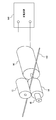
- the coil insertion device includes a delivery wire driving unit 10, a child catheter driving unit 20, and a control circuit 30.
- an insertion device as a medical instrument used for coil embolization treatment of an aneurysm 42 formed in a blood vessel 40 in the brain will be described.
- the use of the insertion device is not limited to the coil embolization treatment of the aneurysm 42.
- the platinum coil 100 for coil embolization is connected to the tip of the delivery wire 110.
- Delivery wire 110 and catheter 120 are inserted into Y connectors 131 and 132, respectively.
- the catheter 120 includes a parent catheter 122 and a child catheter 124.
- the parent catheter 122 and the child catheter 124 are hollow, and the child catheter 124 is inserted into the hollow portion of the parent catheter 122.
- the delivery wire 110 is inserted into the hollow portion of the child catheter 124.
- the delivery wire driving unit 10 is provided near the entrance of the Y connector 131 so that the delivery wire 110 is moved forward and backward. As shown in FIG. 2, the delivery wire drive unit 10 includes a holding roller 12, a feed roller 14, and a motor 16.
- the holding roller 12 and the feeding roller 14 are provided so as to sandwich the delivery wire 110 between the holding roller 12 and the feeding roller 14.
- the feed roller 14 is connected to a motor 16.
- the feed roller 14 is preferably directly connected to the rotor of the motor 16 without using a speed reducer or the like.
- the motor 16 is driven by the current supplied from the constant current source 140.
- the driving force of the motor 16, that is, the insertion force of the platinum coil 100 (delivery wire 110) is determined according to the current value of the motor 16. Therefore, in the present embodiment, the insertion force of the platinum coil 100 (delivery wire 110) is determined by determining the current value of the motor 16.
- the rotation speed (cumulative rotation speed) and rotation speed of the feed roller 14 are detected by the encoder 18, and a signal representing the detection result is input to the control circuit 30. Furthermore, the control circuit 30 calculates the insertion amount (movement distance) of the delivery wire 110 by, for example, multiplying the rotation speed of the feed roller 14 by the circumference of the feed roller 14.
- the child catheter drive unit 20 has the same configuration as the delivery wire drive unit 10.
- the child catheter drive unit 20 is provided near the entrance of the Y connector 132 so that the child catheter 124 is advanced and retracted.
- the control circuit 30 controls the delivery wire driving unit 10 and the child catheter driving unit 20 so as to move the delivery wire 110 and the child catheter 124 in a predetermined manner.
- the control circuit 30 has a predetermined insertion force by executing a program stored in a storage medium such as a ROM (Read Only Memory), a CD (Compact Disc), and a DVD (Digital Versatile Disc).
- a storage medium such as a ROM (Read Only Memory), a CD (Compact Disc), and a DVD (Digital Versatile Disc).
- the delivery wire 110 is moved to control the delivery wire driving unit 10 and the child catheter driving unit 20 so that the platinum coil 100 is inserted into the aneurysm 42.
- the insertion force of the delivery wire 110 is set to an optimal value that allows the platinum coil 100 to be inserted into the aneurysm 42 and prevents damage to the blood vessel 40 in consideration of, for example, the strength of the blood vessel 40. It is done.
- control circuit 30 With reference to FIG. 3, a control structure of a program executed by the control circuit 30 according to the present embodiment will be described.
- step (hereinafter, step is abbreviated as S) 10 the control circuit 30 causes the current of the motor 16 of the delivery wire driving unit 10 to insert the delivery wire 110 into the child catheter 124 with a predetermined insertion force.
- the value, ie, the torque of the motor 16 is set.
- control circuit 30 determines whether or not the rotation speed of the feed roller 14 of the delivery wire driving unit 10, that is, the insertion speed of the delivery wire 110 is zero. If the rotation speed of feed roller 14 of delivery wire drive unit 10 is zero (YES in S20), the process proceeds to S22. If not (NO in S20), the process proceeds to S30.
- control circuit 30 sets the current value of the motor 16 of the delivery wire driving unit 10, that is, the torque to zero.
- control circuit 30 controls the child catheter drive unit 20 so that the child catheter 124 moves backward by a predetermined distance.
- control circuit 30 controls the child catheter drive unit 20 so that the child catheter 124 moves forward by a predetermined distance, preferably the same distance as the retracted distance.
- control circuit 30 determines whether or not the length into which the delivery wire 110 has been inserted has reached a predetermined length. When the length of insertion of delivery wire 110 reaches a predetermined length (YES in S30), the process proceeds to S40. If not (NO in S30), the process returns to S20.
- control circuit 30 stops the insertion of delivery wire 110.
- the operation of the coil insertion device according to the present embodiment based on the above structure and flowchart will be described.
- the current value of the motor 16 of the delivery wire driving unit 10 that is, the torque of the motor 16 is set so that the delivery wire 110 is inserted with a predetermined insertion force. (S10).
- the delivery wire 110 can be automatically inserted without the operation of a doctor or the like. Therefore, it is possible to insert the delivery wire 110 while accurately controlling the insertion force of the delivery wire 110 as compared with a case where a doctor or the like manually performs the operation. As a result, the platinum coil 100 provided at the distal end of the delivery wire 110 can be accurately inserted so that the insertion force applied to the aneurysm 42 does not become excessive.
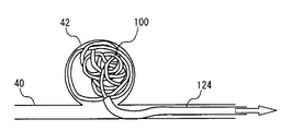
- the insertion resistance increases according to the amount of the platinum coil 100 filled in the aneurysm 42.
- the rotation speed of the feed roller 14 of the delivery wire driving unit 10 that is, the insertion speed of the delivery wire 110 becomes zero (YES in S20).
- the current value of the motor 16 of the delivery wire driving unit 10, that is, the torque is set to zero (S22). That is, the insertion of the delivery wire 110 is temporarily stopped. Further, as shown in FIG. 5, the child catheter drive unit 20 is controlled so that the child catheter 124 moves backward by a predetermined distance (S24).
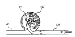
- the child catheter drive unit 20 is controlled so that the child catheter 124 moves forward by a predetermined distance (S26).
- a predetermined distance S26.
- the distal end portion of the child catheter 124 is at a position different from that before the child catheter 124 is pulled out and the density of the platinum coil 100 is low. Therefore, the insertion resistance of the platinum coil 100 is reduced, and the delivery wire 110 can be inserted again.
- the current value of the motor 16 of the delivery wire driving unit 10 that is, the torque of the motor 16 is set so that the delivery wire 110 is inserted with a predetermined insertion force (S10).
- the length of the platinum coil 100 inserted into the aneurysm 42 is determined. Therefore, when the length of insertion of delivery wire 110 reaches a predetermined length (YES in S30), insertion of delivery wire 110 is stopped (S40).
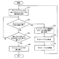
- control circuit 30 determines whether or not the child catheter 124 has been retracted and advanced a predetermined number of times. If the backward movement and advancement of child catheter 124 are repeated a predetermined number of times (YES in S50), the process proceeds to S52. If not (NO in S50), the process proceeds to S24.
- control circuit 30 increases the distance by which the child catheter 124 is moved backward and forward by a predetermined distance.
- the control circuit 30 determines whether or not the distance by which the child catheter 124 is moved backward and forward has reached a predetermined length. When the distance for retreating and advancing child catheter 124 reaches a predetermined length (YES in S54), the process proceeds to S40. If not (NO in S54), the process proceeds to S24.
- the length of the child catheter 124 is about 1 to 2 m. Therefore, even if the child catheter 124 is retracted, the deflection of the child catheter 124 is merely extended, and the distal end portion may not move. Even if the distal end of the child catheter 124 moves, the amount of movement may be slight. In this case, when the child catheter 124 is advanced, the distal end portion of the child catheter 124 may be at the same position again. In any case, the delivery wire 110 cannot be inserted.
- the child catheter drive unit 20 is controlled so that the child catheter 124 moves backward by a predetermined distance (S24). Further, the child catheter drive unit 20 is controlled so that the child catheter 124 moves forward by a predetermined distance (S26).
- the position of the distal end of the child catheter 124 in the aneurysm can be changed. Thereafter, the current value of the motor 16 of the delivery wire driving unit 10, that is, the torque of the motor 16 is set so that the delivery wire 110 is inserted with a predetermined insertion force (S10). Thereby, the platinum coil 100 can be filled evenly in the aneurysm.
- the distal end of the child catheter 124 may fall out of the aneurysm 42. Therefore, when the distance for retreating and advancing the child catheter 124 reaches a predetermined length (YES in S54), it is determined that insertion of delivery wire 110 is impossible, and insertion of delivery wire 110 is stopped. (S40). That is, the insertion of the platinum coil 100 is stopped. Thereby, it is possible to prevent the distal end of the child catheter 124 from coming out of the aneurysm 42.
- the delivery wire 110 is advanced while the child catheter 124 is retracted, and the delivery wire 110 is retracted while the child catheter 124 is advanced, so that the first embodiment and the second embodiment described above are performed. It differs from the form.
- Other structures are the same as those in the first embodiment or the second embodiment described above. Therefore, detailed description thereof will not be repeated here.
- control circuit 30 a control structure of a program executed by control circuit 30 according to the present embodiment will be described. Note that the same step number is assigned to the same process as the program in the first embodiment described above. Therefore, detailed description thereof will not be repeated here.
- control circuit 30 causes the child catheter drive unit 20 and the delivery wire drive unit to advance the delivery wire 110 while the child catheter 124 is retracted by a predetermined distance and while the child catheter 124 is retracted. 10 is controlled.
- control circuit 30 causes the child catheter 124 to advance by a predetermined distance, preferably the same distance as the retracted distance, and to retract the delivery wire 110 while advancing the child catheter 124.
- the child catheter drive unit 20 and the delivery wire drive unit 10 are controlled.
- step S22 the child catheter drive unit 20 and the delivery wire drive unit 10 are controlled so that the child catheter 124 moves backward by a predetermined distance and the delivery wire 110 moves forward while moving the child catheter 124 backward (see FIG. S60).
- the child catheter drive unit 20 and the delivery wire drive unit 10 are controlled so that the child catheter 124 moves forward by a predetermined distance and so that the delivery wire 110 moves backward while moving the child catheter 124 forward (S62). ).
- the platinum coil 100 can be placed in the child catheter 124 when the child catheter 124 is advanced. Therefore, the position of the platinum coil 100 can be maintained.
- the control circuit 30 determines whether or not the rotational speed of the feed roller 14 of the delivery wire driving unit 10, that is, the insertion speed of the delivery wire 110 is higher than a predetermined speed. If the rotation speed of feed roller 14 of delivery wire drive unit 10 is greater than a predetermined speed (YES in S70), the process proceeds to S72. If not (NO in S70), the process proceeds to S20.
- control circuit 30 lowers the current value of the motor 16, that is, the insertion force of the delivery wire 110 by a predetermined value.
- the delivery wire 110 When inserting the delivery wire 110, if the insertion resistance of the delivery wire 110 is extremely small compared to the insertion force, the delivery wire 110 is inserted at a high speed. If the rotation speed of the feed roller 14 of the delivery wire driving unit 10 is fast, the movement of the delivery wire 110 cannot follow, and slippage may occur between the delivery wire 110 and the feed roller 14.
- the rotational speed of feed roller 14 of delivery wire drive unit 10 that is, the insertion speed of delivery wire 110 is greater than a predetermined speed (YES in S70)
- the insertion speed of delivery wire 110 is predetermined.
- the current value of the motor 16, that is, the insertion force of the delivery wire 110 is lowered so that the speed is reached (S72).
- the length of insertion of the delivery wire 110 can be accurately calculated from the rotational speed of the feed roller 14 and the like.
- the coil insertion device further includes a deflection measuring device 50.
- the deflection measuring device 50 is arranged in place of the Y connector 131 into which the delivery wire 110 is inserted or incorporated in the Y connector 131.
- the deflection measuring device 50 is a bent tube having a space 52 at the center. The delivery wire 110 is inserted into the bending measuring instrument 50 while bending along one wall.
- the delivery wire 110 bends in the space 52 in the deflection measuring device 50. As the delivery wire 110 bends, the height h of the crest increases.
- the deflection measuring device 50 is provided with an optical sensor including, for example, a light source (such as an infrared LED) that emits light and a light receiver (such as a phototransistor) disposed at a position facing the light source. Used to detect the degree of bending of the delivery wire 110 (the height h of the crest). Note that the method of measuring the degree of deflection of the delivery wire 110 is not limited to this.
- a signal representing the degree of deflection of the delivery wire 110 measured by the deflection measuring instrument 50 is input to the control circuit 30.
- the control circuit 30 calculates the insertion force of the delivery wire 110 based on a predetermined correlation between the degree of bending of the delivery wire 110 and the compressive force acting on the delivery wire 110 (insertion force of the delivery wire 110). .
- the insertion force of the delivery wire 110 can be accurately calculated from the degree of bending of the delivery wire 110. Therefore, the insertion force of the delivery wire 110 can be accurately controlled by, for example, feedback control.
- the actual current value supplied to the motor 16 that drives the feed roller 14 of the delivery wire driving unit 10 is measured, and the correlation between the current value and the compressive force (the insertion force of the delivery wire 110) acting on the delivery wire 110 is measured. Based on the relationship, the insertion force of the delivery wire 110 may be calculated.
- the delivery wire driving unit 10 and the child catheter driving unit 20 can be controlled so as to insert the delivery wire 110 and the child catheter 124 in accordance with an operation of a doctor or the like.
- This is different from the first to fifth embodiments described above.
- Other structures are the same as those in any of the first to fifth embodiments described above. Therefore, detailed description thereof will not be repeated here.
- the coil insertion device includes a master device 60 that can be connected to the control circuit 30.
- the master machine 60 controls the delivery wire driving unit 10 and the child catheter driving unit 20 so that the delivery wire 110 and the child catheter 124 are inserted in accordance with an operation of a doctor or the like.
- the master device 60 may be connected to the delivery wire driving unit 10 and the child catheter driving unit 20.
- the master device 60 includes, for example, a dial-type delivery wire operation unit 62 and a child catheter operation unit 64.
- the master machine 60 controls the delivery wire driving unit 10 so that the delivery wire 110 is inserted (advanced) and retracted by a distance corresponding to the rotation amount of the delivery wire operation unit 62.
- the master device 60 controls the child catheter drive unit 20 so that the child catheter 124 is inserted and retracted by a distance corresponding to the rotation amount of the child catheter operation unit 64.
- the child catheter 124 and the delivery wire 110 can be inserted according to the operation of a doctor or the like, as in the conventional master-slave device.
Landscapes
- Health & Medical Sciences (AREA)
- Life Sciences & Earth Sciences (AREA)
- Public Health (AREA)
- General Health & Medical Sciences (AREA)
- Veterinary Medicine (AREA)
- Engineering & Computer Science (AREA)
- Biomedical Technology (AREA)
- Heart & Thoracic Surgery (AREA)
- Animal Behavior & Ethology (AREA)
- Surgery (AREA)
- Pulmonology (AREA)
- Biophysics (AREA)
- Anesthesiology (AREA)
- Hematology (AREA)
- Molecular Biology (AREA)
- Medical Informatics (AREA)
- Nuclear Medicine, Radiotherapy & Molecular Imaging (AREA)
- Vascular Medicine (AREA)
- Reproductive Health (AREA)
- Neurosurgery (AREA)
- Surgical Instruments (AREA)
- Media Introduction/Drainage Providing Device (AREA)
Abstract
コイルの挿入装置は、デリバリーワイヤ駆動部(10)と、子カテーテル駆動部(20)と、制御回路(30)とを備える。コイル塞栓用の白金コイル(100)は、デリバリーワイヤ(110)を前進ならびに後退させるように、Yコネクタ(131)の入口付近に設けられる。子カテーテル駆動装置(20)は、子カテーテル(124)を前進ならびに後退させるように、Yコネクタ(132)の入口付近に設けられる。制御回路(30)は、予め定められた挿入力でデリバリーワイヤ(110)を挿入するようにデリバリーワイヤ駆動部(10)を制御し、デリバリーワイヤ(110)を挿入できない場合、子カテーテル(124)を後退させた後に前進させるように子カテーテル駆動装置(20)を制御し、その後、デリバリーワイヤ(110)を挿入するようにデリバリーワイヤ駆動部(10)を制御する。
Description
本発明は、コイルの挿入装置および挿入方法に関し、特に、脳動脈瘤のコイル塞栓治療のためにデリバリーワイヤの先端に取り付けられるコイルを挿入する技術に関する。
従来より、低侵襲であるカテーテルを使用した治療が行われている。たとえば、図12に、くも膜下出血の原因である脳動脈瘤のコイル塞栓術治療に用いられる医療器具を示す。コイル塞栓用の白金コイルはデリバリーワイヤの先頭に接続される。このデリバリーワイヤとカテーテルは、Yコネクタに挿入される。カテーテルは中空であり、デリバリーワイヤはカテーテルの中空部に挿入される。Yコネクタの入り口付近において、医師がデリバリーワイヤとカテーテルを操作する。
カテーテル治療は熟練が必要であり、カテーテルやデリバリーワイヤの操作には微妙なコントロールが必要である。カテーテル治療におけるカテーテルならびにデリバリーワイヤの操作性を改善するために、特開2000-42116号公報ならびに特開2001-157662号公報に記載されているようなマスタースレーブ装置が提案されている。
特開2000-42116号公報
特開2001-157662号公報
マスタースレーブ装置では、医師がマスター部の操作部を操作する。マスター部の操作部の移動量に対応してスレーブ部にあるローラもしくは球体がモータなどにより回転される。瘤に過大な挿入力を加えないように瘤へコイルを挿入するため、マスタースレーブ装置では、スレーブで検出した挿入力がマスター部の操作者へ力覚として与えられる。デリバリーワイヤの挿入力が過剰にならないようにするためには、たとえば操作者への力覚を大きくすることなどが考えられる。
しかしながら、操作者への力覚を大きくすると、デリバリーワイヤの実際の挿入力よりも大きな力覚を操作者に対して与え得る。そのため、操作者は、デリバリーワイヤの挿入力が小さいにもかかわらず、デリバリーワイヤの挿入を止め得る。この場合、デリバリーワイヤの先端に取り付けられたコイルを動脈瘤に挿入するのに必要な挿入力を得ることができない。
本発明は、上述の課題を解決するためになされたものであって、その目的は、コイルの挿入を精度よく行なうことである。
ある局面に係るコイルの挿入装置は、デリバリーワイヤの先端に取り付けられるコイルの挿入装置である。この挿入装置は、デリバリーワイヤが挿入されるカテーテルを動かす第1の駆動部と、デリバリーワイヤを動かす第2の駆動部と、デリバリーワイヤを予め定められた挿入力で挿入するように第2の駆動部を制御し、デリバリーワイヤを予め定められた挿入力で挿入するように第2の駆動部を制御した状態においてデリバリーワイヤが挿入されない場合、カテーテルを後退させた後にカテーテルを前進させるように第1の駆動部を制御し、カテーテルを前進させた後にデリバリーワイヤを予め定められた挿入力で挿入するように第2の駆動部を制御する制御部とを備える。
この構成によると、デリバリーワイヤが予め定められた挿入力で挿入される。デリバリーワイヤが挿入されない場合、カテーテルを後退させた後にカテーテルが前進される。これにより、たとえば動脈瘤内におけるカテーテルの先端の位置を変更することができる。その後、デリバリーワイヤが挿入される。これにより、動脈瘤内においてコイルを満遍なく充填することができる。そのため、手作業で行なう場合に比べてデリバリーワイヤの挿入力を精度よく制御しながら、医師などによる操作によらずにカテーテルおよびデリバリーワイヤを自動的に挿入することができる。その結果、デリバリーワイヤの先端に設けられたコイルの挿入を精度よく行なうことができる。
好ましくは、制御部は、カテーテルを後退させながらデリバリーワイヤを前進させ、カテーテルを前進させながらデリバリーワイヤを後退させるように第1の駆動部および第2の駆動部を制御する。
この構成によると、カテーテルの後退中はデリバリーワイヤが前進される。これにより、カテーテルとともにデリバリーワイヤが後退することを防止することができる。また、カテーテルの前進中はデリバリーワイヤが後退される。これにより、カテーテルとともにデリバリーワイヤが前進することを防止することができる。そのため、コイルの位置を維持することができる。
さらに好ましくは、制御部は、カテーテルの後退および前進が予め定められた回数だけ繰り返された場合、カテーテルを後退ならびに前進させる距離を長くする。
この構成によると、カテーテルの後退および前進が予め定められた回数だけ繰り返された場合、カテーテルを後退させることによりカテーテルの撓みが伸ばされだけで、動脈瘤内におけるカテーテルの先端の位置は変わっていないと考えられる。そこで、カテーテルの撓み分以上にカテーテルを動かすように、カテーテルを後退ならびに前進させる距離が長くされる。これにより、動脈瘤内におけるカテーテルの先端の位置を変更することができる。その後、デリバリーワイヤが挿入される。これにより、動脈瘤内においてコイルを満遍なく充填することができる。
さらに好ましくは、制御部は、カテーテルを後退ならびに前進させる距離が予め定められた距離に達した場合、デリバリーワイヤの挿入を停止する。
この構成によると、カテーテルを後退ならびに前進させる距離が予め定められた距離に達した場合、カテーテルの先端が動脈瘤から抜け出る可能性がある。この場合、コイルの挿入が不可能であると判断されて、デリバリーワイヤの挿入、すなわちコイルの挿入が停止される。これにより、カテーテルの先端が動脈瘤から抜け出ることを防止できる。
さらに好ましくは、制御部は、デリバリーワイヤを挿入する速度が予め定められた速度より大きい場合、デリバリーワイヤの挿入力を下げる。
この構成によると、デリバリーワイヤを挿入する速度が予め定められた速度より大きい場合、デリバリーワイヤの挿入力が下げられる。これにより、たとえばデリバリーワイヤを送り出すローラとデリバリーワイヤとの間で滑りがないようにすることができる。そのため、ローラの回転数などからデリバリーワイヤを挿入した長さを精度よく算出することができる。
さらに好ましくは、制御部は、デリバリーワイヤが挿入された長さが予め定められた長さに達した場合、デリバリーワイヤの挿入を停止する。
この構成によると、デリバリーワイヤが挿入された長さが予め定められた長さに達した場合、デリバリーワイヤの挿入が停止される。これにより、動脈瘤に挿入されるコイルの全長を精度よく制御することができる。
さらに好ましくは、第2の駆動部は、モータの回転によりデリバリーワイヤを動かす。制御部は、モータの電流値およびデリバリーワイヤの撓み度合いのうちの少なくともいずれか一方からデリバリーワイヤの挿入力を算出する。
この構成によると、デリバリーワイヤを動かすモータの電流値もしくはデリバリーワイヤの撓み度合いから、デリバリーワイヤの挿入力を精度よく算出することができる。
さらに好ましくは、挿入装置は、制御部の代わりに、第1の駆動部および第2の駆動部を操作者の操作に応じて制御する機器をさらに備える。
この構成によると、状況に応じて、カテーテルならびにデリバリーワイヤをたとえば医者などの操作に応じて挿入することができる。
本発明によれば、デリバリーワイヤの先端に設けられたコイルの挿入を精度よく行なうことができる。
10 デリバリーワイヤ駆動部、12 抑えローラ、14 送りローラ、16 モータ、18 エンコーダ、20 子カテーテル駆動部、30 制御回路、40 血管、42 動脈瘤、50 測定器、52 空間、60 マスター機、62 デリバリーワイヤ操作部、64 子カテーテル操作部、100 白金コイル、110 デリバリーワイヤ、120 カテーテル、122 親カテーテル、124 子カテーテル、131,132 Yコネクタ、140 定電流源。
以下、図面を参照しつつ、本発明の実施の形態について説明する。以下の説明では、同一の部品には同一の符号を付してある。それらの名称および機能も同一である。したがって、それらについての詳細な説明は繰返さない。
第1の実施の形態
以下、本発明の第1の実施の形態に係るコイルの挿入装置について説明する。図1に示すように、コイルの挿入装置は、デリバリーワイヤ駆動部10と、子カテーテル駆動部20と、制御回路30とを備える。
以下、本発明の第1の実施の形態に係るコイルの挿入装置について説明する。図1に示すように、コイルの挿入装置は、デリバリーワイヤ駆動部10と、子カテーテル駆動部20と、制御回路30とを備える。
なお、本実施の形態においては、一例として、脳内の血管40にできた動脈瘤42のコイル塞栓術治療に用いられる医療器具としての挿入装置について説明する。なお、挿入装置の用途は動脈瘤42のコイル塞栓術治療に限らない。
コイル塞栓用の白金コイル100はデリバリーワイヤ110の先端に接続される。デリバリーワイヤ110とカテーテル120は、Yコネクタ131,132にそれぞれ挿入される。
カテーテル120は、親カテーテル122ならびに子カテーテル124を含む。親カテーテル122ならびに子カテーテル124は中空であり、子カテーテル124は親カテーテル122の中空部に挿入される。デリバリーワイヤ110は子カテーテル124の中空部に挿入される。
デリバリーワイヤ駆動部10は、デリバリーワイヤ110を前進ならびに後退させるように、Yコネクタ131の入口付近に設けられる。デリバリーワイヤ駆動部10は、図2に示すように、抑えローラ12と、送りローラ14と、モータ16とを含む。
抑えローラ12ならびに送りローラ14は、抑えローラ12ならびに送りローラ14とでデリバリーワイヤ110を挟持するように設けられる。送りローラ14はモータ16に連結される。なお、送りローラ14は、減速機などを介さずにモータ16のロータに直接連結されることが好ましい。
モータ16は、定電流源140から供給される電流により駆動する。モータ16の駆動力、すなわち白金コイル100(デリバリーワイヤ110)の挿入力は、モータ16の電流値に応じて定まる。したがって、本実施の形態においては、モータ16の電流値を決定することにより、白金コイル100(デリバリーワイヤ110)の挿入力が決定される。
送りローラ14の回転数(累積回転数)ならびに回転速度は、エンコーダ18により検出され、制御回路30に検出結果を表わす信号が入力される。さらに、制御回路30は、たとえば、送りローラ14の回転数に送りローラ14の円周を乗じることにより、デリバリーワイヤ110の挿入量(移動距離)を算出する。
子カテーテル駆動部20は、デリバリーワイヤ駆動部10と同様の構成を備える。子カテーテル駆動部20は、子カテーテル124を前進ならびに後退させるように、Yコネクタ132の入口付近に設けられる。
制御回路30は、デリバリーワイヤ110および子カテーテル124を予め定められた態様で動かすように、デリバリーワイヤ駆動部10および子カテーテル駆動部20を制御する。
本実施の形態において、制御回路30は、ROM(Read Only Memory)、CD(Compact Disc)およびDVD(Digital Versatile Disc)などの記憶媒体に記憶されたプログラムを実行することにより予め定められた挿入力でデリバリーワイヤ110を動かして、白金コイル100を動脈瘤42の中に挿入するようにデリバリーワイヤ駆動部10および子カテーテル駆動部20を制御する。
デリバリーワイヤ110の挿入力は、たとえば、血管40の強度などを考慮して、白金コイル100を動脈瘤42に挿入することができるとともに、血管40への損傷を防ぐことができる最適な値に定められる。
図3を参照して、本実施の形態に係る制御回路30が実行するプログラムの制御構造について説明する。
ステップ(以下、ステップをSと略す)10にて、制御回路30は、予め定められた挿入力でデリバリーワイヤ110を子カテーテル124内に挿入するように、デリバリーワイヤ駆動部10のモータ16の電流値、すなわちモータ16のトルクを設定する。
S20にて、制御回路30は、デリバリーワイヤ駆動部10の送りローラ14の回転速度、すなわちデリバリーワイヤ110の挿入速度が零であるか否かを判断する。デリバリーワイヤ駆動部10の送りローラ14の回転速度が零であると(S20にてYES)、処理はS22に移される。もしそうでないと(S20にてNO)、処理はS30に移される。
S22にて、制御回路30は、デリバリーワイヤ駆動部10のモータ16の電流値、すなわちトルクを零に設定する。
S24にて、制御回路30は、子カテーテル124が予め定められた距離だけ後退するように子カテーテル駆動部20を制御する。S26にて、制御回路30は、子カテーテル124が予め定められた距離だけ、好ましくは後退した距離と同じ距離だけ前進するように子カテーテル駆動部20を制御する。
S30にて、制御回路30は、デリバリーワイヤ110が挿入された長さが予め定められた長さに達したか否かを判断する。デリバリーワイヤ110が挿入された長さが予め定められた長さに達すると(S30にてYES)、処理はS40に移される。もしそうでないと(S30にてNO)、処理はS20に戻される。
S40にて、制御回路30は、デリバリーワイヤ110の挿入を停止する。
以上のような構造およびフローチャートに基づく、本実施の形態に係るコイルの挿入装置の動作について説明する。
以上のような構造およびフローチャートに基づく、本実施の形態に係るコイルの挿入装置の動作について説明する。
動脈瘤42内に白金コイル100を挿入するため、予め定められた挿入力でデリバリーワイヤ110を挿入するように、デリバリーワイヤ駆動部10のモータ16の電流値、すなわちモータ16のトルクが設定される(S10)。
これにより、医師などによる操作によらずに、デリバリーワイヤ110を自動的に挿入することができる。そのため、医師などが手作業で行なう場合に比べてデリバリーワイヤ110の挿入力を精度よく制御しながらデリバリーワイヤ110を挿入することができる。その結果、動脈瘤42に加える挿入力が過剰にならないように、デリバリーワイヤ110の先端に設けられた白金コイル100の挿入を精度よく行なうことができる。
ところで、デリバリーワイヤ110を予め定められた挿入力で挿入するときに、白金コイル100が動脈瘤42の中に充填される量に応じて、挿入抵抗が大きくなる。挿入抵抗が挿入力よりも大きくなると、図4に示すように、デリバリーワイヤ駆動部10の送りローラ14の回転速度、すなわちデリバリーワイヤ110の挿入速度が零になる(S20にてYES)。
この場合、デリバリーワイヤ駆動部10のモータ16の電流値、すなわちトルクが零に設定される(S22)。すなわち、デリバリーワイヤ110の挿入が一旦停止される。また、図5に示すように、子カテーテル124が予め定められた距離だけ後退するように子カテーテル駆動部20が制御される(S24)。
その後、図6に示すように、子カテーテル124が予め定められた距離だけ前進するように子カテーテル駆動部20が制御される(S26)。子カテーテル124を戻すとき、子カテーテル124の先端部は、引き抜く前とは違う位置であって、白金コイル100の密度が低い位置になる可能性が高い。そのため、白金コイル100の挿入抵抗は小さくなり、デリバリーワイヤ110を再び挿入することができる。
したがって、予め定められた挿入力でデリバリーワイヤ110を挿入するように、デリバリーワイヤ駆動部10のモータ16の電流値、すなわちモータ16のトルクが設定される(S10)。
動脈瘤42に挿入される白金コイル100の長さは決まっている。したがって、デリバリーワイヤ110が挿入された長さが予め定められた長さに達すると(S30にてYES)、デリバリーワイヤ110の挿入が停止される(S40)。
第2の実施の形態
以下、本発明の第2の実施の形態について説明する。本実施の形態は、子カテーテル124の後退と前進とを予め定められた回数だけ繰り返された後においてもデリバリーワイヤ110を動脈瘤42に挿入できない場合、子カテーテル124を後退ならびに前進させる距離を長くする点で、前述の第1の実施の形態と相違する。その他の構造については前述の第1の実施の形態と同じである。したがって、ここではそれらの詳細な説明は繰り返さない。
以下、本発明の第2の実施の形態について説明する。本実施の形態は、子カテーテル124の後退と前進とを予め定められた回数だけ繰り返された後においてもデリバリーワイヤ110を動脈瘤42に挿入できない場合、子カテーテル124を後退ならびに前進させる距離を長くする点で、前述の第1の実施の形態と相違する。その他の構造については前述の第1の実施の形態と同じである。したがって、ここではそれらの詳細な説明は繰り返さない。
図7を参照して、本実施の形態に係る制御回路30が実行するプログラムの制御構造について説明する。なお、前述の第1の実施の形態におけるプログラムと同じ処理には、同じステップ番号を付してある。したがって、ここではそれらの詳細な説明は繰り返さない。
S50にて、制御回路30は、子カテーテル124の後退と前進とを予め定められた回数だけ繰り返したか否かを判断する。子カテーテル124の後退と前進とが予め定められた回数だけ繰り返されると(S50にてYES)、処理はS52に移される。もしそうでないと(S50にてNO)、処理はS24に移される。
S52にて、制御回路30は、子カテーテル124の後退ならびに前進させる距離を予め定められた距離だけ長くする。
S54にて、制御回路30は、子カテーテル124の後退ならびに前進させる距離が予め定められた長さに達したか否かを判断する。子カテーテル124の後退ならびに前進させる距離が予め定められた長さに達すると(S54にてYES)、処理はS40に移される。もしそうでないと(S54にてNO)、処理はS24に移される。
以上のような構造およびフローチャートに基づく、本実施の形態に係るコイルの挿入装置の動作について説明する。
子カテーテル124の長さは1~2m程度である。そのため、子カテーテル124を後退させても、子カテーテル124の撓み分が伸ばされるだけで、先端部は動かない場合がある。また、子カテーテル124の先端が動いたとしても、その移動量がわずかである場合がある。この場合には、子カテーテル124を前進させたときに、子カテーテル124の先端部は再び同じ位置である可能性がある。いずれの場合でも、デリバリーワイヤ110を挿入できない。
したがって、子カテーテル124の後退と前進とが予め定められた回数だけ繰り返されると(S50にてYES)、子カテーテル124の後退ならびに前進させる距離が予め定められた距離だけ長くされる(S52)。
その後、子カテーテル124が予め定められた距離だけ後退するように子カテーテル駆動部20が制御される(S24)。さらに、子カテーテル124が予め定められた距離だけ前進するように子カテーテル駆動部20が制御される(S26)。
これにより、動脈瘤内における子カテーテル124の先端の位置を変更することができる。その後、予め定められた挿入力でデリバリーワイヤ110を挿入するように、デリバリーワイヤ駆動部10のモータ16の電流値、すなわちモータ16のトルクが設定される(S10)。これにより、動脈瘤内において白金コイル100を満遍なく充填することができる。
ところで、子カテーテル124をたとえば数mm以上移動させると、動脈瘤42の中から子カテーテル124先端が抜けるおそれがある。したがって、子カテーテル124の後退ならびに前進させる距離が予め定められた長さに達すると(S54にてYES)、デリバリーワイヤ110の挿入が不可能でると判断されて、デリバリーワイヤ110の挿入が停止される(S40)。すなわち、白金コイル100の挿入が停止される。これにより、子カテーテル124の先端が動脈瘤42から抜け出ることを防止できる。
第3の実施の形態
以下、本発明の第3の実施の形態について説明する。本実施の形態は、子カテーテル124を後退させながらデリバリーワイヤ110を前進させ、子カテーテル124を前進させながらデリバリーワイヤ110を後退させる点で、前述の第1の実施の形態および第2の実施の形態と相違する。その他の構造については前述の第1の実施の形態もしくは第2の実施の形態と同じである。したがって、ここではそれらの詳細な説明は繰り返さない。
以下、本発明の第3の実施の形態について説明する。本実施の形態は、子カテーテル124を後退させながらデリバリーワイヤ110を前進させ、子カテーテル124を前進させながらデリバリーワイヤ110を後退させる点で、前述の第1の実施の形態および第2の実施の形態と相違する。その他の構造については前述の第1の実施の形態もしくは第2の実施の形態と同じである。したがって、ここではそれらの詳細な説明は繰り返さない。
図8を参照して、本実施の形態に係る制御回路30が実行するプログラムの制御構造について説明する。なお、前述の第1の実施の形態におけるプログラムと同じ処理には、同じステップ番号を付してある。したがって、ここではそれらの詳細な説明は繰り返さない。
S60にて、制御回路30は、子カテーテル124が予め定められた距離だけ後退するように、かつ子カテーテル124を後退させながらデリバリーワイヤ110を前進させるように、子カテーテル駆動部20およびデリバリーワイヤ駆動部10を制御する。
S62にて、制御回路30は、子カテーテル124が予め定められた距離だけ、好ましくは後退した距離と同じ距離だけ前進するように、かつ子カテーテル124を前進させながらデリバリーワイヤ110を後退させるように、子カテーテル駆動部20およびデリバリーワイヤ駆動部10を制御する。
以上のような構造およびフローチャートに基づく、本実施の形態に係るコイルの挿入装置の動作について説明する。
デリバリーワイヤ駆動部10の送りローラ14の回転速度、すなわちデリバリーワイヤ110の挿入速度が零になり(S20にてYES)、デリバリーワイヤ駆動部10のモータ16の電流値が零に設定されると(S22)、子カテーテル124が予め定められた距離だけ後退するように、かつ子カテーテル124を後退させながらデリバリーワイヤ110を前進させるように、子カテーテル駆動部20およびデリバリーワイヤ駆動部10が制御される(S60)。
これにより、子カテーテル124とともにデリバリーワイヤ110が後退することを防止することができる。そのため、動脈瘤の挿入した白金コイル100の位置が変わらないようにすることができる。
また、子カテーテル124が予め定められた距離だけ前進するように、かつ子カテーテル124を前進させながらデリバリーワイヤ110を後退させるように、子カテーテル駆動部20およびデリバリーワイヤ駆動部10が制御される(S62)。
これにより、子カテーテル124とともにデリバリーワイヤ110が前進することを防止することができる。そのため、子カテーテル124を前進させるときに、白金コイル100を子カテーテル124の中に入れることができる。そのため、白金コイル100の位置を維持することができる。
第4の実施の形態
以下、本発明の第4の実施の形態について説明する。本実施の形態は、デリバリーワイヤ駆動部10の送りローラ14の回転速度、すなわちデリバリーワイヤ110の挿入速度が予め定められた速度よりも大きい場合、デリバリーワイヤ110の挿入力を下げる点で、前述の第1の実施の形態~第3の実施の形態と相違する。その他の構造については前述の第1の実施の形態~第3の実施の形態のいずれかと同じである。したがって、ここではそれらの詳細な説明は繰り返さない。
以下、本発明の第4の実施の形態について説明する。本実施の形態は、デリバリーワイヤ駆動部10の送りローラ14の回転速度、すなわちデリバリーワイヤ110の挿入速度が予め定められた速度よりも大きい場合、デリバリーワイヤ110の挿入力を下げる点で、前述の第1の実施の形態~第3の実施の形態と相違する。その他の構造については前述の第1の実施の形態~第3の実施の形態のいずれかと同じである。したがって、ここではそれらの詳細な説明は繰り返さない。
図9を参照して、本実施の形態に係る制御回路30が実行するプログラムの制御構造について説明する。なお、前述の第1の実施の形態におけるプログラムと同じ処理には、同じステップ番号を付してある。したがって、ここではそれらの詳細な説明は繰り返さない。
S70にて、制御回路30は、デリバリーワイヤ駆動部10の送りローラ14の回転速度、すなわちデリバリーワイヤ110の挿入速度が予め定められた速度よりも大きいか否かを判断する。デリバリーワイヤ駆動部10の送りローラ14の回転速度が予め定められた速度よりも大きいと(S70にてYES)、処理はS72に移される。もしそうでないと(S70にてNO)、処理はS20に移される。
S72にて、制御回路30は、モータ16の電流値、すなわちデリバリーワイヤ110の挿入力を予め定められた値だけ下げる。
以上のような構造およびフローチャートに基づく、本実施の形態に係るコイルの挿入装置の動作について説明する。
デリバリーワイヤ110を挿入するとき、デリバリーワイヤ110の挿入抵抗が挿入力と比較して極めて小さいと、デリバリーワイヤ110が高速で挿入されることになる。デリバリーワイヤ駆動部10の送りローラ14の回転速度が速いとデリバリーワイヤ110の移動が追従できず、デリバリーワイヤ110と送りローラ14間に滑りが発生し得る。
この場合、デリバリーワイヤ駆動部10の送りローラ14(あるいはモータ16)と一体となって回転するエンコーダ18を使用した、デリバリーワイヤ110の移動距離の計測ができなくなる。そのため、送りローラ14の回転は、デリバリーワイヤ110と送りローラ14とが滑らない速度に抑える必要がある。
そこで、デリバリーワイヤ駆動部10の送りローラ14の回転速度、すなわちデリバリーワイヤ110の挿入速度が予め定められた速度よりも大きいと(S70にてYES)、デリバリーワイヤ110の挿入速度が予め定められた速度になるように、モータ16の電流値、すなわちデリバリーワイヤ110の挿入力が、下げられる(S72)。
これにより、たとえばデリバリーワイヤ110を送り出す送りローラ14とデリバリーワイヤ110との間で滑りがないようにすることができる。そのため、送りローラ14の回転数などからデリバリーワイヤ110を挿入した長さを精度よく算出することができる。
第5の実施の形態
以下、本発明の第5の実施の形態について説明する。本実施の形態は、デリバリーワイヤ110の撓み度合から、デリバリーワイヤ110の挿入力を求める点で、前述の第1の実施の形態~第4の実施の形態と相違する。その他の構造については前述の第1の実施の形態~第4の実施の形態のいずれかと同じである。したがって、ここではそれらの詳細な説明は繰り返さない。
以下、本発明の第5の実施の形態について説明する。本実施の形態は、デリバリーワイヤ110の撓み度合から、デリバリーワイヤ110の挿入力を求める点で、前述の第1の実施の形態~第4の実施の形態と相違する。その他の構造については前述の第1の実施の形態~第4の実施の形態のいずれかと同じである。したがって、ここではそれらの詳細な説明は繰り返さない。
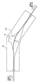
図10に示すように、本実施の形態に係るコイルの挿入装置は、撓み測定器50をさらに備える。撓み測定器50は、デリバリーワイヤ110が挿入されるYコネクタ131の代わりに、もしくはYコネクタ131に組み込まれて配置される。撓み測定器50は、中央部に空間52のある屈曲した管である。デリバリーワイヤ110は一方の壁に沿って曲がりながら撓み測定器50内に挿入される。
デリバリーワイヤ110に圧縮力が作用すると、撓み測定器50内の空間52において、デリバリーワイヤ110が湾曲する。デリバリーワイヤ110の湾曲に伴い、湾曲の山の高さhが増加する。
撓み測定器50には、たとえば光を発する光源器(赤外線LEDなど)と、光源器に対向する位置に配置された受光器(フォトトランジスタなど)とからなる光学式のセンサが設けられ、センサを用いてデリバリーワイヤ110の撓み度合い(湾曲の山の高さh)が検出される。なお、デリバリーワイヤ110の撓み度合いを測定する方法はこれに限らない。
撓み測定器50によって測定されたデリバリーワイヤ110の撓み度合いを表わす信号は、制御回路30に入力される。制御回路30は、予め定められた、デリバリーワイヤ110の撓み度合いとデリバリーワイヤ110に作用する圧縮力(デリバリーワイヤ110の挿入力)との相関関係に基づいて、デリバリーワイヤ110の挿入力を算出する。
これにより、デリバリーワイヤ110の撓み度合いから、デリバリーワイヤ110の挿入力を精度よく算出することができる。そのため、たとえばフィードバック制御などにより、デリバリーワイヤ110の挿入力を精度よく制御することができる。
なお、デリバリーワイヤ駆動部10の送りローラ14を駆動するモータ16に供給される実際の電流値を測定し、電流値とデリバリーワイヤ110に作用する圧縮力(デリバリーワイヤ110の挿入力)との相関関係に基づいて、デリバリーワイヤ110の挿入力を算出するようにしてもよい。
第6の実施の形態
以下、本発明の第6の実施の形態について説明する。本実施の形態は、マスター機60を用いることにより、医師などの操作に応じてデリバリーワイヤ110および子カテーテル124を挿入するようにデリバリーワイヤ駆動部10および子カテーテル駆動部20を制御可能である点で、前述の第1の実施の形態~第5の実施の形態と相違する。その他の構造については前述の第1の実施の形態~第5の実施の形態のいずれかと同じである。したがって、ここではそれらの詳細な説明は繰り返さない。
以下、本発明の第6の実施の形態について説明する。本実施の形態は、マスター機60を用いることにより、医師などの操作に応じてデリバリーワイヤ110および子カテーテル124を挿入するようにデリバリーワイヤ駆動部10および子カテーテル駆動部20を制御可能である点で、前述の第1の実施の形態~第5の実施の形態と相違する。その他の構造については前述の第1の実施の形態~第5の実施の形態のいずれかと同じである。したがって、ここではそれらの詳細な説明は繰り返さない。
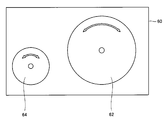
図11に示すように、本実施の形態に係るコイルの挿入装置は、制御回路30に接続可能なマスター機60を備える。マスター機60は、医師などの操作に応じてデリバリーワイヤ110および子カテーテル124を挿入するようにデリバリーワイヤ駆動部10および子カテーテル駆動部20を制御する。なお、制御回路30に代えて、マスター機60をデリバリーワイヤ駆動部10および子カテーテル駆動部20に接続するようにしてもよい。
マスター機60は、たとえばダイヤル式のデリバリーワイヤ操作部62と子カテーテル操作部64とを備える。マスター機60は、デリバリーワイヤ操作部62の回転量に応じた距離だけデリバリーワイヤ110を挿入(前進)ならびに後退するように、デリバリーワイヤ駆動部10を制御する。また、マスター機60は、子カテーテル操作部64の回転量に応じた距離だけ子カテーテル124を挿入ならびに後退するように、子カテーテル駆動部20を制御する。
これにより、従来のマスタースレーブ装置同様に、子カテーテル124ならびにデリバリーワイヤ110をたとえば医者などの操作に応じて挿入することができる。
その他の実施の形態
前述した第1~第6の実施の形態は、任意の組合せで組合わせてもよい。
前述した第1~第6の実施の形態は、任意の組合せで組合わせてもよい。
今回開示された実施の形態は、すべての点で例示であって制限的なものではないと考えられるべきである。本発明の範囲は上記した説明ではなくて請求の範囲によって示され、請求の範囲と均等の意味および範囲内でのすべての変更が含まれることが意図される。
Claims (10)
- デリバリーワイヤ(110)の先端に取り付けられるコイル(100)の挿入装置であって、
前記デリバリーワイヤ(110)が挿入されるカテーテル(124)を動かす第1の駆動部(20)と、
前記デリバリーワイヤ(110)を動かす第2の駆動部(10)と、
前記デリバリーワイヤ(110)を予め定められた挿入力で挿入するように前記第2の駆動部(10)を制御し、前記デリバリーワイヤ(110)を前記予め定められた挿入力で挿入するように前記第2の駆動部(10)を制御した状態において前記デリバリーワイヤ(110)が挿入されない場合、前記カテーテル(124)を後退させた後に前記カテーテル(124)を前進させるように前記第1の駆動部(20)を制御し、前記カテーテル(124)を前進させた後に前記デリバリーワイヤ(110)を前記予め定められた挿入力で挿入するように前記第2の駆動部(10)を制御する制御部(30)とを備える、コイルの挿入装置。 - 前記制御部(30)は、前記カテーテル(124)を後退させながら前記デリバリーワイヤ(110)を前進させ、前記カテーテル(124)を前進させながらデリバリーワイヤ(110)を後退させるように前記第1の駆動部(20)および前記第2の駆動部(10)を制御する、請求の範囲1に記載のコイルの挿入装置。
- 前記制御部(30)は、前記カテーテル(124)の後退および前進が予め定められた回数だけ繰り返された場合、前記カテーテル(124)を後退ならびに前進させる距離を長くする、請求の範囲1に記載のコイルの挿入装置。
- 前記制御部(30)は、前記カテーテル(124)を後退ならびに前進させる距離が予め定められた距離に達した場合、前記デリバリーワイヤ(110)の挿入を停止する、請求の範囲3に記載のコイルの挿入装置。
- 前記制御部(30)は、前記デリバリーワイヤ(110)を挿入する速度が予め定められた速度より大きい場合、前記デリバリーワイヤ(110)の挿入力を下げる、請求の範囲1に記載のコイルの挿入装置。
- 前記制御部(30)は、前記デリバリーワイヤ(110)が挿入された長さが予め定められた長さに達した場合、前記デリバリーワイヤ(110)の挿入を停止する、請求の範囲1に記載のコイルの挿入装置。
- 前記第2の駆動部(10)は、モータ(16)の回転により前記デリバリーワイヤ(110)を動かし、
前記制御部(30)は、前記モータ(16)の電流値および前記デリバリーワイヤ(110)の撓み度合いのうちの少なくともいずれか一方から前記デリバリーワイヤ(110)の挿入力を算出する、請求の範囲1に記載のコイルの挿入装置。 - 前記制御部(30)の代わりに、前記第1の駆動部(20)および前記第2の駆動部(10)を操作者の操作に応じて制御する機器(60)をさらに備える、請求の範囲1に記載のコイルの挿入装置。
- デリバリーワイヤ(110)が挿入されるカテーテル(124)を動かす第1の駆動部(20)と、前記デリバリーワイヤ(110)を動かす第2の駆動部(10)とが設けられ、前記デリバリーワイヤ(110)の先端に取り付けられるコイル(100)の挿入方法であって、
前記デリバリーワイヤ(110)を予め定められた挿入力で挿入するように前記第2の駆動部(10)を制御するステップと、
前記デリバリーワイヤ(110)を前記予め定められた挿入力で挿入するように前記第2の駆動部(10)を制御した状態において前記デリバリーワイヤ(110)が挿入されない場合、前記カテーテル(124)を後退させた後に前記カテーテル(124)を前進させるように前記第1の駆動部(20)を制御するステップと、
前記カテーテル(124)を前進させた後に前記デリバリーワイヤ(110)を前記予め定められた挿入力で挿入するように前記第2の駆動部(10)を制御するステップとを備える、コイルの挿入方法。 - デリバリーワイヤ(110)の先端に取り付けられるコイル(100)の挿入装置であって、
前記デリバリーワイヤ(110)が挿入されるカテーテル(124)を動かすための第1の駆動手段(20)と、
前記デリバリーワイヤ(110)を動かすための第2の駆動手段(10)と、
前記デリバリーワイヤ(110)を予め定められた挿入力で挿入するように前記第2の駆動手段(10)を制御し、前記デリバリーワイヤ(110)を前記予め定められた挿入力で挿入するように前記第2の駆動手段(10)を制御した状態において前記デリバリーワイヤ(110)が挿入されない場合、前記カテーテル(124)を後退させた後に前記カテーテル(124)を前進させるように前記第1の駆動手段(20)を制御し、前記カテーテル(124)を前進させた後に前記デリバリーワイヤ(110)を前記予め定められた挿入力で挿入するように前記第2の駆動手段(10)を制御するための制御手段(30)とを備える、コイルの挿入装置。
Priority Applications (2)
| Application Number | Priority Date | Filing Date | Title |
|---|---|---|---|
| US12/995,113 US9351735B2 (en) | 2008-05-29 | 2009-03-18 | Insertion device and insertion method of coil |
| EP09754503.2A EP2294988B1 (en) | 2008-05-29 | 2009-03-18 | Device for inserting an embolic coil |
Applications Claiming Priority (2)
| Application Number | Priority Date | Filing Date | Title |
|---|---|---|---|
| JP2008-140990 | 2008-05-29 | ||
| JP2008140990A JP5334035B2 (ja) | 2008-05-29 | 2008-05-29 | コイルの挿入装置 |
Publications (2)
| Publication Number | Publication Date |
|---|---|
| WO2009144995A1 true WO2009144995A1 (ja) | 2009-12-03 |
| WO2009144995A8 WO2009144995A8 (ja) | 2010-04-08 |
Family
ID=41376881
Family Applications (1)
| Application Number | Title | Priority Date | Filing Date |
|---|---|---|---|
| PCT/JP2009/055256 Ceased WO2009144995A1 (ja) | 2008-05-29 | 2009-03-18 | コイルの挿入装置および挿入方法 |
Country Status (4)
| Country | Link |
|---|---|
| US (1) | US9351735B2 (ja) |
| EP (1) | EP2294988B1 (ja) |
| JP (1) | JP5334035B2 (ja) |
| WO (1) | WO2009144995A1 (ja) |
Cited By (2)
| Publication number | Priority date | Publication date | Assignee | Title |
|---|---|---|---|---|
| EP2266473A4 (en) * | 2008-04-10 | 2012-07-18 | Ntn Toyo Bearing Co Ltd | LINEAR OBJECT ACTUATING CONTROLLER WHICH CONTROLS THE OPERATION OF A LINEAR OBJECT BY AN OPERATOR |
| WO2021131784A1 (ja) * | 2019-12-25 | 2021-07-01 | 朝日インテック株式会社 | ワイヤ送出装置、及び、薬液注入装置 |
Families Citing this family (36)
| Publication number | Priority date | Publication date | Assignee | Title |
|---|---|---|---|---|
| US9254123B2 (en) | 2009-04-29 | 2016-02-09 | Hansen Medical, Inc. | Flexible and steerable elongate instruments with shape control and support elements |
| US20120071752A1 (en) | 2010-09-17 | 2012-03-22 | Sewell Christopher M | User interface and method for operating a robotic medical system |
| US9138166B2 (en) | 2011-07-29 | 2015-09-22 | Hansen Medical, Inc. | Apparatus and methods for fiber integration and registration |
| US10149720B2 (en) | 2013-03-08 | 2018-12-11 | Auris Health, Inc. | Method, apparatus, and a system for facilitating bending of an instrument in a surgical or medical robotic environment |
| US10653863B1 (en) * | 2013-03-15 | 2020-05-19 | Corindus, Inc. | Robotic percutaneous device wiper |
| US10376672B2 (en) * | 2013-03-15 | 2019-08-13 | Auris Health, Inc. | Catheter insertion system and method of fabrication |
| EP3689284B1 (en) | 2013-10-24 | 2025-02-26 | Auris Health, Inc. | System for robotic-assisted endolumenal surgery |
| JP6440071B2 (ja) | 2014-03-31 | 2018-12-19 | パナソニックIpマネジメント株式会社 | 柔軟長尺部材の装置、柔軟長尺部材の方法、及び制御プログラム |
| US10046140B2 (en) * | 2014-04-21 | 2018-08-14 | Hansen Medical, Inc. | Devices, systems, and methods for controlling active drive systems |
| US10792464B2 (en) | 2014-07-01 | 2020-10-06 | Auris Health, Inc. | Tool and method for using surgical endoscope with spiral lumens |
| US9561083B2 (en) | 2014-07-01 | 2017-02-07 | Auris Surgical Robotics, Inc. | Articulating flexible endoscopic tool with roll capabilities |
| US9744335B2 (en) | 2014-07-01 | 2017-08-29 | Auris Surgical Robotics, Inc. | Apparatuses and methods for monitoring tendons of steerable catheters |
| US11819636B2 (en) | 2015-03-30 | 2023-11-21 | Auris Health, Inc. | Endoscope pull wire electrical circuit |
| GB2547915B (en) | 2016-03-02 | 2018-05-23 | Cook Medical Technologies Llc | Medical Filament delivery apparatus |
| WO2017169279A1 (ja) * | 2016-03-31 | 2017-10-05 | 学校法人慶應義塾 | 内視鏡ホルダー |
| KR102638260B1 (ko) * | 2016-03-31 | 2024-02-19 | 각고호우징 게이오기주크 | 내시경 홀더 |
| US10765471B2 (en) | 2016-04-15 | 2020-09-08 | Bolder Surgical, Llc | Electrosurgical sealer and divider |
| US10799686B2 (en) * | 2016-04-21 | 2020-10-13 | Johan Willem Pieter Marsman | Guidewire torquer |
| US10463439B2 (en) | 2016-08-26 | 2019-11-05 | Auris Health, Inc. | Steerable catheter with shaft load distributions |
| EP3624668A4 (en) | 2017-05-17 | 2021-05-26 | Auris Health, Inc. | Exchangeable working channel |
| CN117017505A (zh) | 2018-03-28 | 2023-11-10 | 奥瑞斯健康公司 | 复合器械和机器人系统 |
| KR20230169481A (ko) | 2018-08-07 | 2023-12-15 | 아우리스 헬스, 인코포레이티드 | 카테터 제어와의 변형-기반 형상 감지의 조합 |
| US11179212B2 (en) | 2018-09-26 | 2021-11-23 | Auris Health, Inc. | Articulating medical instruments |
| CN113286543A (zh) | 2018-12-28 | 2021-08-20 | 奥瑞斯健康公司 | 具有可关节运动区段的医疗器械 |
| US11617627B2 (en) | 2019-03-29 | 2023-04-04 | Auris Health, Inc. | Systems and methods for optical strain sensing in medical instruments |
| IT201900006657A1 (it) * | 2019-05-08 | 2020-11-08 | Guido Danieli | Robot per chirurgia endovascolare dotato di sistema opto-aptico per misurare e rappresentare le forze che si oppongono all’avanzamento di un catetere o una guida all’interno del sistema endovascolare |
| WO2020225839A1 (en) * | 2019-05-08 | 2020-11-12 | Guido Danieli | Opto-haptic system to measure and represent forces opposing catheter or guide wire penetration into the vascular system for robots for endovascular surgery |
| JP2022544554A (ja) | 2019-08-15 | 2022-10-19 | オーリス ヘルス インコーポレイテッド | 複数の屈曲部を有する医療デバイス |
| JP2022166336A (ja) * | 2019-09-26 | 2022-11-02 | テルモ株式会社 | カテーテルデバイス |
| CN114901188B (zh) | 2019-12-31 | 2026-02-17 | 奥瑞斯健康公司 | 动态滑轮系统 |
| JP7530177B2 (ja) * | 2020-01-31 | 2024-08-07 | 朝日インテック株式会社 | 薬液注入装置 |
| CN111544741A (zh) * | 2020-06-22 | 2020-08-18 | 中国科学院自动化研究所 | 协同递送导丝和微导管的同轴操控装置 |
| ES3053795T3 (en) * | 2021-04-19 | 2026-01-26 | Microbot Medical Ltd | Device for automatically inserting and manipulating a medical tool into and within a bodily lumen |
| US12564458B2 (en) | 2022-08-01 | 2026-03-03 | Imperative Care, Inc. | Method of robotically driving a multi catheter assembly above the aortic arch |
| CN114146291B (zh) * | 2021-12-08 | 2022-12-06 | 上海神玑医疗科技有限公司 | 血管用导丝介入装置 |
| CN116440392B (zh) * | 2023-03-07 | 2024-04-05 | 极限人工智能有限公司 | 基于麦克纳姆轮的导丝驱动装置、方法及介入手术机器人 |
Citations (5)
| Publication number | Priority date | Publication date | Assignee | Title |
|---|---|---|---|---|
| JPS59181122A (ja) * | 1983-03-31 | 1984-10-15 | オリンパス光学工業株式会社 | 内視鏡等における進退誘導装置 |
| US5108407A (en) * | 1990-06-08 | 1992-04-28 | Rush-Presbyterian St. Luke's Medical Center | Method and apparatus for placement of an embolic coil |
| JP2000042116A (ja) | 1998-07-10 | 2000-02-15 | Mitsubishi Electric Inf Technol Center America Inc | 医療器具操作装置 |
| JP2000512515A (ja) * | 1995-12-01 | 2000-09-26 | エンドマトリックス,インコーポレイティド | フィラメント状及び微粒子状物質を体内に移植する装置、システム及び方法 |
| JP2001157662A (ja) | 1999-12-02 | 2001-06-12 | Japan Science & Technology Corp | 力伝達機構およびそれを使用した棒状体の挿入操作感覚装置 |
Family Cites Families (10)
| Publication number | Priority date | Publication date | Assignee | Title |
|---|---|---|---|---|
| SI0901341T1 (en) * | 1997-01-03 | 2005-04-30 | Biosense Webster, Inc. | Bend-responsive catheter |
| IL123646A (en) * | 1998-03-11 | 2010-05-31 | Refael Beyar | Remote control catheterization |
| US6280457B1 (en) * | 1999-06-04 | 2001-08-28 | Scimed Life Systems, Inc. | Polymer covered vaso-occlusive devices and methods of producing such devices |
| US7766894B2 (en) * | 2001-02-15 | 2010-08-03 | Hansen Medical, Inc. | Coaxial catheter system |
| AU2002305341A1 (en) * | 2001-05-06 | 2002-11-18 | Stereotaxis, Inc. | System and methods for advancing a catheter |
| US20050272971A1 (en) * | 2002-08-30 | 2005-12-08 | Olympus Corporation | Medical treatment system, endoscope system, endoscope insert operation program, and endoscope device |
| US20060100610A1 (en) * | 2004-03-05 | 2006-05-11 | Wallace Daniel T | Methods using a robotic catheter system |
| US9717468B2 (en) * | 2006-01-10 | 2017-08-01 | Mediguide Ltd. | System and method for positioning an artificial heart valve at the position of a malfunctioning valve of a heart through a percutaneous route |
| US8419717B2 (en) * | 2006-06-13 | 2013-04-16 | Intuitive Surgical Operations, Inc. | Control system configured to compensate for non-ideal actuator-to-joint linkage characteristics in a medical robotic system |
| JP4878526B2 (ja) * | 2006-09-05 | 2012-02-15 | 国立大学法人 名古屋工業大学 | 可撓性線状体の圧縮力計測装置 |
-
2008
- 2008-05-29 JP JP2008140990A patent/JP5334035B2/ja not_active Expired - Fee Related
-
2009
- 2009-03-18 US US12/995,113 patent/US9351735B2/en not_active Expired - Fee Related
- 2009-03-18 EP EP09754503.2A patent/EP2294988B1/en not_active Not-in-force
- 2009-03-18 WO PCT/JP2009/055256 patent/WO2009144995A1/ja not_active Ceased
Patent Citations (5)
| Publication number | Priority date | Publication date | Assignee | Title |
|---|---|---|---|---|
| JPS59181122A (ja) * | 1983-03-31 | 1984-10-15 | オリンパス光学工業株式会社 | 内視鏡等における進退誘導装置 |
| US5108407A (en) * | 1990-06-08 | 1992-04-28 | Rush-Presbyterian St. Luke's Medical Center | Method and apparatus for placement of an embolic coil |
| JP2000512515A (ja) * | 1995-12-01 | 2000-09-26 | エンドマトリックス,インコーポレイティド | フィラメント状及び微粒子状物質を体内に移植する装置、システム及び方法 |
| JP2000042116A (ja) | 1998-07-10 | 2000-02-15 | Mitsubishi Electric Inf Technol Center America Inc | 医療器具操作装置 |
| JP2001157662A (ja) | 1999-12-02 | 2001-06-12 | Japan Science & Technology Corp | 力伝達機構およびそれを使用した棒状体の挿入操作感覚装置 |
Non-Patent Citations (1)
| Title |
|---|
| See also references of EP2294988A4 * |
Cited By (4)
| Publication number | Priority date | Publication date | Assignee | Title |
|---|---|---|---|---|
| EP2266473A4 (en) * | 2008-04-10 | 2012-07-18 | Ntn Toyo Bearing Co Ltd | LINEAR OBJECT ACTUATING CONTROLLER WHICH CONTROLS THE OPERATION OF A LINEAR OBJECT BY AN OPERATOR |
| WO2021131784A1 (ja) * | 2019-12-25 | 2021-07-01 | 朝日インテック株式会社 | ワイヤ送出装置、及び、薬液注入装置 |
| JP2021101891A (ja) * | 2019-12-25 | 2021-07-15 | 朝日インテック株式会社 | ワイヤ送出装置、及び、薬液注入装置 |
| JP7398273B2 (ja) | 2019-12-25 | 2023-12-14 | 朝日インテック株式会社 | ワイヤ送出装置、及び、薬液注入装置 |
Also Published As
| Publication number | Publication date |
|---|---|
| JP5334035B2 (ja) | 2013-11-06 |
| WO2009144995A8 (ja) | 2010-04-08 |
| US20110077681A1 (en) | 2011-03-31 |
| EP2294988A1 (en) | 2011-03-16 |
| JP2009285150A (ja) | 2009-12-10 |
| US9351735B2 (en) | 2016-05-31 |
| EP2294988B1 (en) | 2014-06-25 |
| EP2294988A4 (en) | 2012-10-17 |
Similar Documents
| Publication | Publication Date | Title |
|---|---|---|
| JP5334035B2 (ja) | コイルの挿入装置 | |
| US9565990B2 (en) | Endoscope apparatus with slave device and master device | |
| CN102573600B (zh) | 医疗装置 | |
| JP5165162B2 (ja) | 内視鏡 | |
| CN101198370B (zh) | 内窥镜处置工具和内窥镜用处置工具装置 | |
| JP2014004310A (ja) | 医療器具 | |
| JP5443801B2 (ja) | 張力検出手段及びそれを用いたマニピュレータ | |
| JP2009516574A (ja) | 曲げ可能な装置の形状を決定する方法 | |
| JP6840851B2 (ja) | 制御装置、自走式内視鏡システム及び制御方法 | |
| JP2006314775A (ja) | 内視鏡装置 | |
| JP2009018116A5 (ja) | ||
| CN110636814A (zh) | Oss引导和监测系统、控制器以及方法 | |
| JP6138405B1 (ja) | 挿入装置 | |
| WO2015118773A1 (ja) | 挿入装置 | |
| JPWO2018225538A1 (ja) | 医療機器駆動装置及び力情報の算出方法 | |
| JP3549434B2 (ja) | 電動湾曲式内視鏡 | |
| CN104759018A (zh) | 缆线布置器 | |
| WO2017138105A1 (ja) | マニピュレータシステム | |
| CN108135443A (zh) | 插入装置 | |
| JP4963067B2 (ja) | 圧縮力計測装置 | |
| CN218382163U (zh) | 压力检测机构 | |
| JP6289787B1 (ja) | 挿入装置の制御装置及び挿入装置 | |
| CN117717420A (zh) | 驱动细长型医疗器械的控制系统 | |
| JP2969531B2 (ja) | 内視鏡装置 | |
| JP2009285151A (ja) | 線状体の引抜装置 |
Legal Events
| Date | Code | Title | Description |
|---|---|---|---|
| 121 | Ep: the epo has been informed by wipo that ep was designated in this application |
Ref document number: 09754503 Country of ref document: EP Kind code of ref document: A1 |
|
| WWE | Wipo information: entry into national phase |
Ref document number: 12995113 Country of ref document: US |
|
| NENP | Non-entry into the national phase |
Ref country code: DE |
|
| WWE | Wipo information: entry into national phase |
Ref document number: 2009754503 Country of ref document: EP |