WO2009145216A1 - クラッチレリーズ軸受 - Google Patents
クラッチレリーズ軸受 Download PDFInfo
- Publication number
- WO2009145216A1 WO2009145216A1 PCT/JP2009/059667 JP2009059667W WO2009145216A1 WO 2009145216 A1 WO2009145216 A1 WO 2009145216A1 JP 2009059667 W JP2009059667 W JP 2009059667W WO 2009145216 A1 WO2009145216 A1 WO 2009145216A1
- Authority
- WO
- WIPO (PCT)
- Prior art keywords
- bearing
- clutch release
- seal member
- inner ring
- outer ring
- Prior art date
- Legal status (The legal status is an assumption and is not a legal conclusion. Google has not performed a legal analysis and makes no representation as to the accuracy of the status listed.)
- Ceased
Links
Images





Classifications
-
- F—MECHANICAL ENGINEERING; LIGHTING; HEATING; WEAPONS; BLASTING
- F16—ENGINEERING ELEMENTS AND UNITS; GENERAL MEASURES FOR PRODUCING AND MAINTAINING EFFECTIVE FUNCTIONING OF MACHINES OR INSTALLATIONS; THERMAL INSULATION IN GENERAL
- F16D—COUPLINGS FOR TRANSMITTING ROTATION; CLUTCHES; BRAKES
- F16D23/00—Details of mechanically-actuated clutches not specific for one distinct type
- F16D23/12—Mechanical clutch-actuating mechanisms arranged outside the clutch as such
- F16D23/14—Clutch-actuating sleeves or bearings; Actuating members directly connected to clutch-actuating sleeves or bearings
-
- F—MECHANICAL ENGINEERING; LIGHTING; HEATING; WEAPONS; BLASTING
- F16—ENGINEERING ELEMENTS AND UNITS; GENERAL MEASURES FOR PRODUCING AND MAINTAINING EFFECTIVE FUNCTIONING OF MACHINES OR INSTALLATIONS; THERMAL INSULATION IN GENERAL
- F16C—SHAFTS; FLEXIBLE SHAFTS; ELEMENTS OR CRANKSHAFT MECHANISMS; ROTARY BODIES OTHER THAN GEARING ELEMENTS; BEARINGS
- F16C19/00—Bearings with rolling contact, for exclusively rotary movement
- F16C19/02—Bearings with rolling contact, for exclusively rotary movement with bearing balls essentially of the same size in one or more circular rows
- F16C19/14—Bearings with rolling contact, for exclusively rotary movement with bearing balls essentially of the same size in one or more circular rows for both radial and axial load
- F16C19/16—Bearings with rolling contact, for exclusively rotary movement with bearing balls essentially of the same size in one or more circular rows for both radial and axial load with a single row of balls
- F16C19/163—Bearings with rolling contact, for exclusively rotary movement with bearing balls essentially of the same size in one or more circular rows for both radial and axial load with a single row of balls with angular contact
-
- F—MECHANICAL ENGINEERING; LIGHTING; HEATING; WEAPONS; BLASTING
- F16—ENGINEERING ELEMENTS AND UNITS; GENERAL MEASURES FOR PRODUCING AND MAINTAINING EFFECTIVE FUNCTIONING OF MACHINES OR INSTALLATIONS; THERMAL INSULATION IN GENERAL
- F16C—SHAFTS; FLEXIBLE SHAFTS; ELEMENTS OR CRANKSHAFT MECHANISMS; ROTARY BODIES OTHER THAN GEARING ELEMENTS; BEARINGS
- F16C33/00—Parts of bearings; Special methods for making bearings or parts thereof
- F16C33/72—Sealings
- F16C33/76—Sealings of ball or roller bearings
- F16C33/78—Sealings of ball or roller bearings with a diaphragm, disc, or ring, with or without resilient members
- F16C33/7886—Sealings of ball or roller bearings with a diaphragm, disc, or ring, with or without resilient members mounted outside the gap between the inner and outer races, e.g. sealing rings mounted to an end face or outer surface of a race
-
- F—MECHANICAL ENGINEERING; LIGHTING; HEATING; WEAPONS; BLASTING
- F16—ENGINEERING ELEMENTS AND UNITS; GENERAL MEASURES FOR PRODUCING AND MAINTAINING EFFECTIVE FUNCTIONING OF MACHINES OR INSTALLATIONS; THERMAL INSULATION IN GENERAL
- F16C—SHAFTS; FLEXIBLE SHAFTS; ELEMENTS OR CRANKSHAFT MECHANISMS; ROTARY BODIES OTHER THAN GEARING ELEMENTS; BEARINGS
- F16C33/00—Parts of bearings; Special methods for making bearings or parts thereof
- F16C33/72—Sealings
- F16C33/76—Sealings of ball or roller bearings
- F16C33/80—Labyrinth sealings
-
- F—MECHANICAL ENGINEERING; LIGHTING; HEATING; WEAPONS; BLASTING
- F16—ENGINEERING ELEMENTS AND UNITS; GENERAL MEASURES FOR PRODUCING AND MAINTAINING EFFECTIVE FUNCTIONING OF MACHINES OR INSTALLATIONS; THERMAL INSULATION IN GENERAL
- F16J—PISTONS; CYLINDERS; SEALINGS
- F16J15/00—Sealings
- F16J15/16—Sealings between relatively-moving surfaces
- F16J15/164—Sealings between relatively-moving surfaces the sealing action depending on movements; pressure difference, temperature or presence of leaking fluid
-
- F—MECHANICAL ENGINEERING; LIGHTING; HEATING; WEAPONS; BLASTING
- F16—ENGINEERING ELEMENTS AND UNITS; GENERAL MEASURES FOR PRODUCING AND MAINTAINING EFFECTIVE FUNCTIONING OF MACHINES OR INSTALLATIONS; THERMAL INSULATION IN GENERAL
- F16J—PISTONS; CYLINDERS; SEALINGS
- F16J15/00—Sealings
- F16J15/16—Sealings between relatively-moving surfaces
- F16J15/32—Sealings between relatively-moving surfaces with elastic sealings, e.g. O-rings
- F16J15/3248—Sealings between relatively-moving surfaces with elastic sealings, e.g. O-rings provided with casings or supports
- F16J15/3252—Sealings between relatively-moving surfaces with elastic sealings, e.g. O-rings provided with casings or supports with rigid casings or supports
- F16J15/3256—Sealings between relatively-moving surfaces with elastic sealings, e.g. O-rings provided with casings or supports with rigid casings or supports comprising two casing or support elements, one attached to each surface, e.g. cartridge or cassette seals
-
- F—MECHANICAL ENGINEERING; LIGHTING; HEATING; WEAPONS; BLASTING
- F16—ENGINEERING ELEMENTS AND UNITS; GENERAL MEASURES FOR PRODUCING AND MAINTAINING EFFECTIVE FUNCTIONING OF MACHINES OR INSTALLATIONS; THERMAL INSULATION IN GENERAL
- F16J—PISTONS; CYLINDERS; SEALINGS
- F16J15/00—Sealings
- F16J15/44—Free-space packings
- F16J15/447—Labyrinth packings
- F16J15/4476—Labyrinth packings with radial path
-
- F—MECHANICAL ENGINEERING; LIGHTING; HEATING; WEAPONS; BLASTING
- F16—ENGINEERING ELEMENTS AND UNITS; GENERAL MEASURES FOR PRODUCING AND MAINTAINING EFFECTIVE FUNCTIONING OF MACHINES OR INSTALLATIONS; THERMAL INSULATION IN GENERAL
- F16C—SHAFTS; FLEXIBLE SHAFTS; ELEMENTS OR CRANKSHAFT MECHANISMS; ROTARY BODIES OTHER THAN GEARING ELEMENTS; BEARINGS
- F16C2361/00—Apparatus or articles in engineering in general
- F16C2361/43—Clutches, e.g. disengaging bearing
-
- F—MECHANICAL ENGINEERING; LIGHTING; HEATING; WEAPONS; BLASTING
- F16—ENGINEERING ELEMENTS AND UNITS; GENERAL MEASURES FOR PRODUCING AND MAINTAINING EFFECTIVE FUNCTIONING OF MACHINES OR INSTALLATIONS; THERMAL INSULATION IN GENERAL
- F16C—SHAFTS; FLEXIBLE SHAFTS; ELEMENTS OR CRANKSHAFT MECHANISMS; ROTARY BODIES OTHER THAN GEARING ELEMENTS; BEARINGS
- F16C33/00—Parts of bearings; Special methods for making bearings or parts thereof
- F16C33/72—Sealings
- F16C33/76—Sealings of ball or roller bearings
- F16C33/80—Labyrinth sealings
- F16C33/805—Labyrinth sealings in addition to other sealings, e.g. dirt guards to protect sealings with sealing lips
-
- F—MECHANICAL ENGINEERING; LIGHTING; HEATING; WEAPONS; BLASTING
- F16—ENGINEERING ELEMENTS AND UNITS; GENERAL MEASURES FOR PRODUCING AND MAINTAINING EFFECTIVE FUNCTIONING OF MACHINES OR INSTALLATIONS; THERMAL INSULATION IN GENERAL
- F16D—COUPLINGS FOR TRANSMITTING ROTATION; CLUTCHES; BRAKES
- F16D2300/00—Special features for couplings or clutches
- F16D2300/08—Details or arrangements of sealings not provided for in group F16D3/84
Definitions
- This invention relates to a clutch release bearing. Specifically, the present invention relates to a sealing structure for a clutch release bearing of the type in which an outer ring rotates in contact with a rotating member of a clutch mechanism.
- a clutch release bearing is incorporated in a clutch device disposed between an automobile engine and a transmission.
- These clutch release bearings are of the outer ring rotating / inner ring fixing type in which the outer ring rotates by contacting with a rotating member of the clutch mechanism such as a diaphragm spring, and the outer ring fixing in which the inner ring rotates by contacting with the rotating member of the clutch mechanism. / Some types of inner ring rotation. If water enters the inside of the clutch release bearing, the lubricating oil such as grease enclosed in the bearing deteriorates, rust is generated inside the bearing, and the life of the bearing is reduced.
- JP 2006-189086 A Patent Document 1
- JP 2001-311437 A Patent Document 2
- JP 2006-189086 A Patent Document 1
- JP 2001-311437 A Patent Document 2
- a seal member fixed to the inner ring and slidably contacting the outer ring is disposed on the front side where the rotating member of the clutch mechanism is disposed.
- a seal member fixed to the outer ring and in sliding contact with the inner ring is disposed on the rear side opposite to the axial direction.
- Japanese Patent Laying-Open No. 2006-9826 Patent Document 3 describes a sealing structure in which an outer ring rotating / inner ring fixed clutch release bearing is configured such that a seal member fixed to an outer ring is in sliding contact with an inner ring.
- FIG. 9 is a partial cross-sectional view of a clutch release bearing 210 having substantially the same configuration as the clutch release bearing described in Patent Document 1.
- the clutch release bearing 210 includes an outer ring 220 having a flange 222 having a convex arc surface extending radially inward, an inner ring 230 having a flat flange 232 extending radially inward, A clutch of a type that includes a plurality of rolling elements 214 that are rotatably accommodated between the inner ring 230 and the outer ring 220, and the outer ring 220 rotates by contact between the rotating member 212 of the clutch mechanism and the flange 222 of the outer ring 220. Release bearing.
- a seal 250 is disposed on the front side of the outer ring 220 where the flange 222 is formed, in contact with the side surface of the flange 232 of the inner ring 230, and a side lip 252 integrally joined to the seal 250 is provided. It is configured to be in sliding contact with the flange portion 222 of the outer ring 220.
- a seal 240 is disposed on the rear side of the outer ring 220 on the side opposite to the side where the flange portion 222 is formed in the axial direction and is fitted into the inner peripheral surface of the outer ring 220.
- the formed seal lip 242 is configured to be in sliding contact with the outer diameter surface of the inner ring 230. Therefore, since the clutch release bearing 210 has a structure in which lubricating oil does not leak easily and muddy water does not easily enter, it is considered that good lubricity and water resistance can be maintained.
- the front-side seal is designed to reduce torque by forming a labyrinth with the seal in a non-contact proximity state with the outer ring or by making a light contact.
- the seal lip is lightly contacted with the outer diameter surface of the inner ring to reduce the torque, the seal rotates with the outer ring. May disappear. And on rainy days and rough roads with puddles, a large amount of muddy water is applied to the clutch housing. Reach.
- muddy water enters the gap between the outer ring and the inner ring on the rear side of the clutch release bearing, the muddy water enters the bearing from the gap between the inner ring and the seal lip if there is no allowance for the seal lip. Penetrates and degrades lubricating oil such as grease and shortens bearing life.
- FIG. 10 shows a partial cross-sectional view of a clutch release bearing 210 having substantially the same configuration as the clutch release bearing described in Patent Document 2.
- a self-aligning elastic sleeve is provided on the inner periphery of an inner ring 230 in which a plurality of balls (rolling elements) 214 are arranged so as to roll between the outer ring 220.
- 260 is fixed.
- a seal member 262 is formed to protrude from the elastic sleeve 260 at one end of the inner ring 230, and the tip of the seal member 262 bifurcated is brought into sliding contact with the inner surface of the flange portion 222 of the outer ring 220.
- the gap between the inner rings 230 is closed. Further, at the other end in the axial direction, the slinger 270 is externally fitted and fixed to the inner ring 230, and the tip of the oil seal 272 attached to the outer ring is brought into sliding contact with the slinger 270 from the outside of the bearing so that the gap between the outer ring 220 and the inner ring 230 is reached. It is configured to close the gap. Therefore, since the clutch release bearing 210 has a structure in which lubricating oil does not leak easily and muddy water does not easily enter, it is considered that good lubricity and water resistance can be maintained.
- the seal member 242 is in contact with the inner surface of the flange 222 of the outer ring 220, so that torque is generated by friction between the flange 222 and the seal member 242 due to the rotation of the outer ring 220. There is a problem that loss occurs.
- a problem to be solved by the present invention is to provide a clutch release bearing that improves water resistance and reduces torque loss.
- the clutch release bearing takes the following means.
- the first invention of the present invention comprises an outer ring, an inner ring, a plurality of rolling elements arranged so as to be able to roll between the outer ring and the inner ring, and a cage for rotatably holding the rolling element,
- An outer ring flange portion extending radially inward is formed at one end of the outer ring, and a side surface outside the bearing of the outer ring flange portion is a contact surface with which a rotating member of the clutch mechanism comes into contact.
- a seal member fixed to the outer ring is disposed on one side where the portion is formed and the opposite side in the axial direction, and a seal lip formed at a radially inner end of the seal member is provided on the inner ring.
- a clutch release bearing configured to be in sliding contact with the outer peripheral surface of An annular mating member integrated with the inner ring is disposed on the outer side of the bearing of the seal member, and the mating member is extended toward the outer side of the bearing on the side surface of the outer side of the seal member.
- An axial lip extending outward in the radial direction is formed, the axial lip forms a labyrinth in a non-contacting proximity state with the counterpart member, and a radial direction is formed at the root of the axial lip to the seal member.
- the axial lip of the seal member extends outward in the radial direction of the mating member and covers the gap between the axial lip and the mating member. Therefore, even if muddy water is applied to the bearing from the outside in the radial direction, muddy water is prevented from directly entering the gap between the seal member covered by the axial lip and the counterpart member. And since the groove that opens radially outward is formed at the base of the seal member of the axial lip, the muddy water applied to the axial lip flows in the circumferential direction from the groove of the base of the axial lip. The water is drained from below the bearing.
- a second invention of the present invention is a clutch release bearing according to the first invention,
- a groove is formed in the outer diameter surface of the inner ring at a bearing outer position where the seal lip of the seal member is in sliding contact with the outer diameter surface of the inner ring.
- a third invention of the present invention is a clutch release bearing according to the first invention or the second invention,
- a concave portion or a convex portion is formed on a side surface of the seal member on the outer side of the bearing at a radially inner position than the axial lip on the side surface of the seal member on the outer side of the bearing.
- a fourth invention of the present invention is a clutch release bearing according to any one of the first to third inventions,
- the mating member and the seal member form a labyrinth in a non-contact proximity state.
- the sealing member and the mating member form a labyrinth, even if muddy water enters between the sealing member and the mating member from the gap between the axial lip and the mating member, the sealing member and the mating member Infiltration of muddy water from the gap inward in the radial direction is suppressed.
- a fifth invention of the present invention is a clutch release bearing according to any one of the first to third inventions
- the mating member is a guide for smoothly aligning the clutch release bearing, and a slinger that is fixed to the inner ring and extends radially outward is disposed between the seal member and the guide.
- the seal member and the slinger form a labyrinth in the non-contact proximity state in the axial direction, and the slinger and the guide are in a separated state in which no labyrinth is formed in the axial direction.
- the slinger and the guide are separated from each other in the axial direction, and no labyrinth is formed.
- a sixth invention of the present invention is a clutch release bearing according to any one of the first to third inventions,
- the mating member is an inner ring flange extending radially outward from the inner ring, and the inner ring flange is formed with a protrusion that expands toward the inside of the bearing.
- the tip is in a non-contact proximity state to the side surface of the seal member outside the bearing.
- the tip of the protrusion formed on the inner ring collar is brought into a non-contacting proximity to the outer side surface of the seal member to form a labyrinth. Intrusion of muddy water interposed in the radial direction is suppressed.
- the protrusion formed on the inner ring flange portion has a diameter that increases toward the inside of the bearing, and a groove is formed at the base of the protrusion, so that the muddy water interposed radially outward of the protrusion is a protrusion. It gathers in the groove at the base of the part, flows in the circumferential direction, and drains down the bearing.
- a seventh invention of the present invention comprises an outer ring, an inner ring, and a plurality of rolling elements arranged so as to be able to roll between the outer ring and the inner ring,
- An outer ring flange portion extending radially inward is formed at one end of the outer ring, and a side surface outside the bearing of the outer ring flange portion is a contact surface with which a diaphragm spring contacts, and the outer ring flange portion is formed.
- a clutch release bearing in which an inner ring flange portion extending radially inward is formed at a predetermined distance from one end of the inner ring on the same side as the one side formed;
- a seal member is disposed from one side end portion of the inner ring to the inner ring flange portion, and the seal member includes an axial lip disposed in a non-contact proximity state with the tip of the outer ring flange portion, A seal lip is formed which is arranged in a non-contact proximity state with a side surface inside the bearing of the outer ring collar portion.
- the labyrinth is formed between the tip of the outer ring collar portion and the axial lip of the seal member, entry of foreign matter such as muddy water into the clutch release bearing can be suppressed. Further, since the side surface of the outer ring flange portion on the inner side of the bearing and the seal lip of the seal member form a labyrinth, the outflow of lubricating oil such as grease from the inside of the bearing can be suppressed. Since the axial lip and the seal lip of the seal member are not in contact with the outer ring, torque loss can be reduced compared to the contact type. Therefore, it is possible to provide a clutch release bearing capable of maintaining good lubricity and water resistance and reducing torque loss.
- an eighth invention of the present invention is the clutch release bearing according to the first invention, wherein the outer surface of the outer ring collar is radially outward from the bearing inner side toward the bearing outer side. It is characterized by chamfering that is inclined from the inside to the outside in the radial direction. According to the eighth aspect of the invention, the chamfering that is inclined from the radially inner side to the radially outer side from the bearing inner side toward the bearing outer side is performed on the bearing outer side at the tip of the outer ring collar portion.
- a ninth invention of the present invention is the clutch release bearing according to the first invention or the second invention, wherein the tip of the outer ring collar portion is not in contact with the axial lip of the seal member.
- the range in which the adjacent state is set to have a narrow width in the axial direction.
- the water resistance of the clutch release bearing is improved, and good lubricity and water resistance can be maintained.
- the muddy water is in a position where the seal lip on the outer diameter surface of the inner ring is in sliding contact. It flows in a circumferential direction through a groove formed at the bearing outer position, and is drained from below the bearing. Therefore, intrusion of muddy water into the bearing from the position where the seal lip is in sliding contact with the inner ring is suppressed.
- the protrusion formed on the inner ring flange portion and the seal member form a labyrinth, so that the muddy water interposed between the seal member and the inner ring flange portion is radially inward. Intrusion is deterred.
- the protrusion formed on the inner ring flange portion has a diameter that increases toward the inside of the bearing, and a groove is formed at the base of the protrusion, so that the muddy water interposed radially outward of the protrusion is a protrusion. It gathers in the groove at the base of the part, flows in the circumferential direction, and drains down the bearing.
- FIG. 1 shows a partial cross-sectional view of a clutch release bearing 10 in Embodiment 1 of the present invention.
- the clutch release bearing 10 includes an outer ring 20, an inner ring 30, a plurality of balls (rolling elements) 14 that are rotatably arranged between the outer ring 20 and the inner ring 30, and a cage 16 that holds the balls 14 in a freely rotatable manner.
- an outer ring rotation type clutch release bearing An outer ring flange 22 extending radially inward is formed at one end of the outer ring 20, and an axially outer side surface of the outer ring flange 22 is a contact surface 24 with which the diaphragm spring 12 contacts. ing.
- This diaphragm spring 12 is a rotating member of the clutch mechanism of the present invention.
- the outer ring 20 and the inner ring 30 are formed by pressing.
- a first seal member 40 that is externally fitted and fixed to the outer ring 20 is disposed on the opposite side in the axial direction from one side where the outer ring collar portion 22 is formed.
- the first seal member 40 is the seal member of the present invention.
- the first seal member 40 is an annular member having a substantially L-shaped cross section, and a rubber cover 42 is attached to a metal cored bar 41.
- a seal lip 44 is formed integrally with the covering portion 42 at the radially inner end of the first seal member 40, and the seal lip 44 is configured to be in sliding contact with the outer diameter surface 32 of the inner ring 30. ing.
- An annular guide 50 for smooth alignment when the clutch release bearing 10 moves in the axial direction is disposed outside the bearing of the first seal member 40.
- This guide 50 is the counterpart member of the present invention.
- a flange 52 formed on the inner diameter side of the guide 50 is press-fitted on the inner diameter side of the inner ring 30 so that the guide 50 and the inner ring 30 are integrated.
- An axial lip 46 is formed on the outer side surface of the first seal member 40 so as to extend toward the outer side of the bearing and extend radially outward of the guide 50. The axial lip 46 is brought into a non-contact proximity state with the guide 50 to form a labyrinth.
- the outer diameter surface of the axial lip 46 is parallel to the axial direction, and a groove 47 opened radially outward is formed at the base portion of the axial lip 46 to the first seal member 40.
- the covering portion 42, the seal lip 44, and the axial lip 46 of the first seal member 40 are made of rubber, but these may be made of a soft resin.
- the first seal member 40 and the guide 50 are in a non-contact proximity state in the axial direction and form a labyrinth.
- FIG. 2 shows a partial plan view of the first seal member 40 as viewed from the outside of the bearing. As shown in FIG. 2, the recesses 48 are formed on the concentric circles at almost equal intervals.
- an inner ring flange 36 that extends radially inward is formed at one end of the inner ring 30 on the same side as the one side on which the outer ring flange 22 is formed. Are formed at intervals of.
- the inner ring 30 is formed with a cylindrical cylindrical portion 34 that is parallel to the axial direction from the inner ring flange 36 to the inside of the bearing.
- a second seal member 60 is disposed from the tubular portion 34 of the inner ring 30 to the inner ring flange 36.
- the second seal member 60 is an annular member in which a rubber core 64 is attached to a metal core 62 and is press-fitted from the side where the inner ring collar 36 is formed to the inner ring 30.
- the second seal member 60 includes a rubber axial lip 66 formed integrally with the covering portion 64 and a rubber seal lip 68 formed integrally with the covering portion 64.
- the axial lip 66 is configured so as to be close to the tip 26 of the outer ring flange portion 22 at a narrow interval and not in contact with the outer ring 20, and the seal lip 68 is narrow on the side surface of the outer ring flange portion 22 on the inner side of the bearing. It is set as the structure which adjoins by a space
- the axial lip 46 of the first seal member 40 extends to the outside in the radial direction of the guide 50. Therefore, even if muddy water is applied to the clutch release bearing 10 from the outside in the radial direction, muddy water may directly enter the gap between the first seal member 40 covered by the axial lip 46 of the first seal member 40 and the guide 50. Deterred. Since the groove 47 opened radially outward is formed at the root of the axial lip 46 to the first seal member 40, the muddy water applied to the axial lip 46 is groove 47 at the root of the axial lip 46. From the lower side of the clutch release bearing 10. And since the axial lip 46 forms a labyrinth in the non-contact proximity state with the guide 50, intrusion of muddy water into the bearing through the gap between the axial lip 46 and the guide 50 is suppressed.
- the first seal member 40 and the guide 50 are in a non-contact proximity state in the axial direction and form a labyrinth, muddy water is first generated from the gap between the axial lip 46 and the guide 50. Even when it enters between the seal member 40 and the guide 50, the intrusion of muddy water from the gap between the first seal member 40 and the guide 50 to the inside in the radial direction of the bearing is suppressed.
- the first seal member 40 is fixed to the outer ring 20 and rotates together with the outer ring 20, so that the concave portion 48 formed on the outer side surface of the bearing of the first seal member 40 rotates and the first seal member 40 rotates. 1
- the air flow in the circumferential direction is generated in the gap between the seal member 40 and the guide 50. Therefore, when muddy water enters the gap between the first seal member 40 and the guide 50 from the gap between the axial lip 46 and the guide 50, the muddy water is guided outward in the radial direction of the bearing by centrifugal force. Therefore, intrusion of muddy water from the gap between the first seal member 40 and the guide 50 to the inside in the radial direction of the bearing is suppressed. Therefore, according to Example 1, the water resistance of the clutch release bearing is improved.
- the concave portion 48 is provided on the side surface of the first seal member 40, but a convex portion may be provided instead of the concave portion 48 to generate a circumferential air flow.
- the outer diameter surface of the axial lip 46 of the first seal member 40 is parallel to the axial direction. However, the outer diameter surface of the axial lip 46 may be increased toward the outside of the bearing. If the outer diameter surface of the axial lip 46 is configured to expand toward the outside of the bearing, muddy water attached to the outer diameter surface of the axial lip 46 is likely to collect in the groove 47.
- FIG. 3 shows a partial cross-sectional view of the clutch release bearing 10A according to the second embodiment of the present invention.
- the clutch release bearing 10A is provided with a metal slinger 54 extending radially outward between the first seal member 40 and the guide 50, And the feature is that the recessed part 48 is not formed in the side surface outside the bearing of the first seal member 40.
- the slinger 54 is integrated with the inner ring 30 and the guide 50 by press-fitting the flange 52 of the guide 50 into the inner diameter surface of the inner ring 30 with the inner diameter portion 56 of the slinger 54 fitted on the flange 52 of the guide 50. Yes.
- the slinger 54 is sandwiched between the end 38 of the inner ring 30 and the bearing inner side surface of the guide 50 on the inner diameter side. And it is made into the state which inclined to the bearing inward in the radial direction outer side than the outer diameter surface 32 of the inner ring
- the distal end of the slinger 54 in the radial direction is not in contact with the axial lip 46 of the first seal member 40.
- the first seal member 40 and the slinger 54 form a labyrinth in a non-contact proximity state in the axial direction, and the slinger 54 and the guide 50 are in a separated state in which no labyrinth is formed in the axial direction.
- the seal lip 44 formed at the radially inner end of the first seal member 40 has a thin thickness, a long leg, and a low rigidity, and is in light contact with the outer diameter surface 32 of the inner ring 30. Lower torque is achieved.
- the other structure of 10 A of clutch release bearings is the same as that of the clutch release bearing 10 of Example 1, the same code
- the axial lip 46 of the first seal member 40 extends to the outside in the radial direction of the guide 50. Therefore, even if muddy water is applied to the clutch release bearing 10A from the outside in the radial direction, muddy water may directly enter the gap between the first seal member 40 and the guide 50 covered with the axial lip 46 of the first seal member 40. Deterred. Since a groove 47 opened radially outward is formed at the root of the axial lip 46 to the first seal member 40, the muddy water applied to the axial lip 46 is removed from the groove 47 at the root of the axial lip 46. , Flows in the circumferential direction and drains from below the clutch release bearing 10A. Since the axial lip 46 forms a labyrinth in the non-contact proximity state with the guide 50, the intrusion of muddy water from the gap between the axial lip 46 and the guide 50 to the inside in the radial direction of the bearing is suppressed.
- the slinger 54 and the guide 50 are separated from each other in the axial direction and no labyrinth is formed, so that intrusion of muddy water is easy.
- a labyrinth is formed between the first seal member 40 and the slinger 54, it is difficult to enter muddy water. Therefore, even when muddy water enters between the first seal member 40 and the guide 50 through the gap between the axial lip 46 and the guide 50, the muddy water is trapped in the gap between the slinger 54 and the guide 50, and the first seal member 40 and the slinger It is difficult to enter between 54.
- the concave portion 48 is not formed on the side surface outside the bearing of the first seal member 40.
- the concave portion 48 is formed on the side surface outside the bearing of the first seal member 40 as in the first embodiment. It is good also as a structure. Moreover, it is good also as a structure which provides a convex part instead of the recessed part 48 and produces the flow of the air of the circumferential direction. Then, the outer diameter surface of the axial lip 46 may be expanded toward the outside of the bearing. If the outer diameter surface of the axial lip 46 is configured to expand toward the outside of the bearing, the muddy water adhering to the outer diameter surface of the axial lip 46 is likely to gather in the groove 47 at the base of the axial lip 46.
- the water resistance of the clutch release bearing is improved, the deterioration of grease is suppressed, and the shortening of the bearing life is suppressed. Further, the generation of abnormal noise is suppressed by suppressing the deterioration of the grease.
- FIG. 4 is a partial cross-sectional view of the clutch release bearing 110 according to the third embodiment of the present invention.
- the clutch release bearing 110 is an outer ring rotating type provided with an outer ring 120, an inner ring 130, a plurality of balls (rolling elements) 114 arranged so as to be able to roll between the outer ring 120 and the inner ring 130, and a cage 116.
- This is a clutch release bearing.
- An outer ring flange 122 extending radially inward is formed at one end of the outer ring 120, and a side surface outside the bearing of the outer ring flange 122 is a contact surface 124 with which the diaphragm spring 112 contacts.
- This diaphragm spring 112 is a rotating member of the clutch mechanism of the present invention.
- the outer ring 120 and the inner ring 130 are formed by pressing.
- a first seal member 140 that is externally fitted and fixed to the outer ring 120 is disposed on the opposite side in the axial direction from one side where the outer ring flange 122 is formed.
- This first seal member 140 is the seal member of the present invention.
- the first seal member 140 is an annular member, and a rubber cover 142 is attached to a metal core 141.
- a seal lip 144 is formed integrally with the covering portion 142 at the radially inner end of the first seal member 140, and the seal lip 144 is configured to be in sliding contact with the outer diameter surface 132 of the inner ring 130.
- a groove 136 is formed in the outer diameter surface 132 of the inner ring 130 from the position where the seal lip 144 of the first seal member 140 is in sliding contact with the outer diameter surface 132 of the inner ring 130 to the bearing outer position.
- an inner ring collar portion 134 in which an end portion of the inner ring 130 is extended radially outward is disposed outside the first seal member 140 in a non-contact state with the first seal member 140.
- This inner ring collar part 134 is the mating member of the present invention.
- An axial lip 146 is formed on the outer side of the bearing of the first seal member 140 so as to expand toward the outer side of the bearing and extend radially outward of the inner ring collar portion 134. The axial lip 146 is brought into a non-contact proximity state with the inner ring collar portion 134 to form a labyrinth.
- a groove 147 is formed on the outer side in the radial direction of the root of the axial lip 146 to the first seal member 140.
- the inner ring collar portion 134 is formed with a protruding portion 138 whose diameter increases toward the inside of the bearing by cutting and raising, and the tip of the protruding portion 138 is not in contact with the outer side surface of the first seal member 140. Proximity.
- a self-aligning elastic sleeve 150 is fixed to the inner periphery of the inner ring 130, and a seal lip 152 is formed from the elastic sleeve 150 at one end of the inner ring 130 on the same side as the outer ring flange 122 is formed.
- the tip formed in a protruding manner and bifurcated into the seal lip 152 is in a light contact state with the inner surface of the outer ring flange portion 122.
- the axial lip 146 of the first seal member 140 extends to the outer side in the radial direction of the inner ring collar portion 134. Therefore, even if muddy water is applied to the clutch release bearing 110 from the outside in the radial direction, muddy water directly enters the gap between the first seal member 140 covered with the axial lip 146 of the first seal member 140 and the inner ring collar portion 134. Is deterred. Since the axial lip 146 expands toward the outer side of the bearing, a groove 147 is formed on the outer side in the radial direction of the base portion of the axial lip 146 to the first seal member 140.
- the muddy water applied in the flow flows in the circumferential direction from the groove 147 at the base of the axial lip 146 and is drained from below the clutch release bearing 110. Since the axial lip 146 forms a labyrinth in the non-contact proximity state with the inner ring flange portion 134, intrusion of muddy water from the gap between the axial lip 146 and the inner ring flange portion 134 to the inside in the radial direction of the bearing is suppressed.
- the tip of the projection 138 formed on the inner ring collar 134 is brought into a non-contacting proximity to the outer surface of the bearing of the first seal member 140 to form a labyrinth, the first seal member 140 and the inner ring collar Intrusion of muddy water intervening in the radial direction inside 134 is suppressed.
- the protrusion 138 formed on the inner ring collar portion 134 is configured to increase in diameter toward the inside of the bearing, a groove 139 is formed radially outward at the base of the protrusion 138, and the diameter of the protrusion 138 is increased.
- the muddy water intervening outward in the direction gathers in the groove 139 at the base of the protrusion 138, flows in the circumferential direction, and is drained below the bearing.
- the muddy water is the first seal member 140 on the outer diameter surface 132 of the inner ring 130. It flows in the circumferential direction through the groove 136 formed at the bearing outer position where the seal lip 144 is in sliding contact, and is drained from below the bearing. Therefore, intrusion of muddy water into the bearing from the portion where the seal lip 144 is in sliding contact with the inner ring 130 is suppressed. Therefore, the water resistance of the clutch release bearing is improved, leading to an extended life and improved reliability.
- a groove may be provided on the outer diameter surface 32 of the inner ring 30 at the bearing outer position from the position where the seal lip 44 of the first seal member 40 is in sliding contact.
- the outer diameter side of the end portion 38 of the inner ring 30 may be chamfered so that a groove is formed between the chamfered portion and the side surface of the guide 50 or slinger 54.
- FIG. 5 shows a partial cross-sectional view of the clutch release bearing 310 according to the fourth embodiment of the present invention.
- the clutch release bearing 310 is an outer ring rotation type clutch that includes an outer ring 320, an inner ring 330, a plurality of balls (rolling elements) 314 that are arranged to roll between the outer ring 320 and the inner ring 330, and a cage 316. Release bearing.
- An outer ring flange 322 extending radially inward is formed at one end of the outer ring 320, and the outer surface of the outer ring flange 322 is a contact surface 324 with which the diaphragm spring 312 comes into contact.
- An inner ring flange 334 extending radially inward is formed at a predetermined distance from one end of the inner ring 330 on the same side as the one on which the outer ring flange 322 is formed. ing.
- the inner ring 330 is formed with a cylindrical cylindrical portion 332 in the axial direction from the inner ring flange 334 to the inside of the bearing.
- the outer ring 320 and the inner ring 330 are formed by pressing.
- a first seal member 340 is disposed across the tubular portion 332 of the inner ring 330 and the inner ring collar 334.
- the first seal member 340 corresponds to the seal member of the present invention.
- the first seal member 340 is an annular member in which a rubber core 342 is attached to a metal core 342, and is pressed into the inner ring 330 from the side where the inner ring collar 334 is formed.
- the inner ring 330 is fixed to the inner ring 330 by engaging with an engaging groove 336 formed in the tubular portion 332 of the inner ring 330.
- the first seal member 340 includes a rubber axial lip 344 formed integrally with the covering portion 343 and a rubber seal lip 346 formed integrally with the covering portion 343.
- the axial lip 344 is configured to be close to the tip 326 of the outer ring flange 322 at a narrow interval and not in contact with the outer ring 320, and the seal lip 346 is narrower than the inner side surface of the outer ring flange 322. It is set as the structure which adjoins by a space
- FIG. 4 the covering portion 343, the axial lip 344, and the seal lip 346 are made of rubber, but these may be made of a soft resin.
- a second seal member 350 fitted to the outer ring 320 is attached to the other end of the clutch release bearing 310, and a seal lip 352 formed at the tip of the second seal member 350 is an outer periphery of the inner ring 330. It is set as the structure which slidably contacts a surface.
- a labyrinth is formed between the tip 326 of the outer ring flange 322 and the axial lip 344 of the first seal member 340. Intrusion to the inside can be suppressed. Further, since the inner side surface of the outer ring flange portion 322 and the seal lip 346 of the first seal member 340 form a labyrinth, it is possible to suppress the outflow of lubricating oil such as grease from the inside of the bearing. Since the axial lip 344 and the seal lip 346 of the first seal member 340 are not in contact with the outer ring flange 322, torque loss can be reduced as compared with the case where a contact type seal member is used. .
- seal lip 346 provided on the inner side of the bearing of the outer ring flange portion 322 is a non-contact type, it is not necessary to set the seal lip thick in preparation for deformation due to wear or the like unlike the contact type, and the seal lip 346 Since the thickness can be reduced, the volume of the seal lip 346 can be reduced as compared with the contact type, and the volume for enclosing lubricating oil such as grease can be increased. Therefore, it is possible to provide a clutch release bearing that can maintain good lubricity and water resistance and reduce torque loss.
- FIG. 6 shows a partial cross-sectional view of a clutch release bearing 310A according to the fifth embodiment of the present invention.
- Clutch release bearing 310A is formed with a chamfered portion 328 that is chamfered from the inner side of the bearing toward the outer side of the bearing toward the outer side of the outer ring flange portion 322 so as to incline from the inner side in the radial direction to the outer side in the radial direction. It is characterized by being.
- Other configurations of the clutch release bearing 310A of the fifth embodiment are the same as those of the clutch release bearing 310 of the fourth embodiment, and thus the same reference numerals are given and detailed description thereof is omitted.
- FIG. 7 shows a partial cross-sectional view of the clutch release bearing 310B according to the sixth embodiment of the present invention.
- the clutch release bearing 310B is chamfered on the outer side of the tip 326 of the outer ring flange 322 to be chamfered in the same manner as in the fifth embodiment to form a chamfered portion 328, and further on the bearing inner side of the tip 326 of the outer ring flange 322.
- the chamfered portion 329 is formed by chamfering.
- a range where the tip 326 of the outer ring collar 322 is in a non-contact proximity state with respect to the axial lip 344 of the first seal member 340 is narrow in the axial direction.
- the clutch release bearing 310B of the sixth embodiment has the same configuration as that of the clutch release bearing 310 of the fourth embodiment except that it is chamfered on both sides of the tip 326 of the outer ring flange portion 322, and therefore, the same reference numerals are given. Detailed description will be omitted.
- chamfering is performed on both sides of the tip 326 of the outer ring collar 322, and the range where the tip 326 of the outer ring collar 322 is in a non-contacting proximity state with respect to the axial lip 344 of the first seal member 340 is as follows.
- the width is narrow in the axial direction, even when the outer ring flange 322 is deformed when the torque is transmitted from the diaphragm spring 312 and the tip 326 of the outer ring flange 322 contacts the axial lip 344, the contact width is small. Therefore, torque loss due to contact friction can be kept low.
- FIG. 8A shows a configuration in which a notch 327A is formed by notching the outer side of the bearing of the tip 326 of the outer ring collar 322 in a rectangular shape, and the width of the tip 326 of the outer ring collar 322 is reduced in the axial direction.
- This is an example in which the extending direction of the axial lip 344 facing the tip 326 of the outer ring collar 322 is substantially parallel to the axis.
- FIG. 8B is an example in which an arcuate arc-shaped portion 327B is formed on the outer side of the bearing of the tip 326 of the outer ring flange portion 322, and the inner side of the bearing of the outer ring flange portion 322 is chamfered to form a chamfered portion 329. is there.
- FIG. 8C shows a configuration in which both ends of the tip 326 of the outer ring 320 are chamfered, and the tip of the axial lip 344 is bent radially outward.
- the labyrinth formed by the chamfered portion 328 and the axial lip 344 is inclined radially outward toward the outside of the bearing, foreign matters such as muddy water intervening in the labyrinth are subjected to centrifugal force due to the rotation of the outer ring 320. This has the effect of being guided to the outside of the bearing.
- FIG. 8C shows a configuration in which both ends of the tip 326 of the outer ring 320 are chamfered, and the tip of the axial lip 344 is bent radially outward.
- an inclined portion 327D is formed on the outer side of the tip 326 of the outer ring flange 322 by bending so as to incline from the inner side of the bearing toward the outer side of the bearing from the radially inner side to the radially outer side. It is a thing. Since the inclined portion is formed by bending, the outer ring 320 is easily processed as compared with the method of forming the inclined portion by chamfering by cutting.
- clutch release bearing according to the present invention can be implemented in various forms within the scope of the idea of the invention.
Landscapes
- Engineering & Computer Science (AREA)
- General Engineering & Computer Science (AREA)
- Mechanical Engineering (AREA)
- Mechanical Operated Clutches (AREA)
- Sealing Using Fluids, Sealing Without Contact, And Removal Of Oil (AREA)
Abstract
耐水性を向上させたクラッチレリーズ軸受を提供する。 クラッチレリーズ軸受10の外輪鍔部22が形成された一側と軸線方向の反対側には、外輪20に外嵌め固定された第1シール部材40が配設されている。そして、第1シール部材40の径方向内方の先端には、内輪30の外径面32に摺接するシールリップ44が形成されている。そして、第1シール部材40の軸受外方には円環状のガイド50が配設されており、第1シール部材40の軸受外方の側面には、軸受外方に向けて延設され、ガイド50の径方向外方まで延びたアキシアルリップ46が形成されている。そして、アキシアルリップ46はガイド50と非接触の近接状態とされラビリンスを形成している。そして、アキシアルリップ46の第1シール部材40への付け根部には径方向外方に開口した溝47が形成されている。
Description
この発明はクラッチレリーズ軸受に関する。具体的には、クラッチ機構の回転部材と接触して外輪が回転するタイプのクラッチレリーズ軸受の密封構造に関する。
自動車のエンジンとトランスミッションとの間に配設されるクラッチ装置にはクラッチレリーズ軸受が組み込まれている。このクラッチレリーズ軸受には、ダイヤフラムスプリングなどのクラッチ機構の回転部材と接触して外輪が回転する外輪回転/内輪固定のタイプのものと、クラッチ機構の回転部材と接触して内輪が回転する外輪固定/内輪回転のタイプのものがある。
このクラッチレリーズ軸受の内部に水が入ってしまうと、軸受内部に封入されたグリース等の潤滑油が劣化し、軸受内部に錆が発生して、軸受の寿命低下を引き起こす。
そこで、クラッチレリーズ軸受には、軸受外部から軸受内部への水等の異物の侵入を防ぎ、軸受内部に封入されているグリース等の潤滑油の軸受外部への流出を防ぐために、軸線方向の両端において、内輪又は外輪のいずれか一方に固定され他方に接触または非接触とされたシールを内輪と外輪の間に配置した構成の密封構造を採用しているものがある。
このクラッチレリーズ軸受の内部に水が入ってしまうと、軸受内部に封入されたグリース等の潤滑油が劣化し、軸受内部に錆が発生して、軸受の寿命低下を引き起こす。
そこで、クラッチレリーズ軸受には、軸受外部から軸受内部への水等の異物の侵入を防ぎ、軸受内部に封入されているグリース等の潤滑油の軸受外部への流出を防ぐために、軸線方向の両端において、内輪又は外輪のいずれか一方に固定され他方に接触または非接触とされたシールを内輪と外輪の間に配置した構成の密封構造を採用しているものがある。
先行技術文献として、特開2006-189086号公報(特許文献1)及び特開2001-311437号公報(特許文献2)には、外輪回転/内輪固定のクラッチレリーズ軸受の密封構造が記載されている。特許文献1に記載のクラッチレリーズ軸受では、クラッチ機構の回転部材が配設されるフロント側には内輪に固定され外輪に摺接するシール部材が配設されている。そして、軸線方向の反対側のリヤ側には外輪に固定され内輪に摺接するシール部材が配設されている。また、特開2006-9826号公報(特許文献3)には、外輪回転/内輪固定のクラッチレリーズ軸受について、外輪に固定されたシール部材が内輪に摺接する構成の密封構造が記載されている。
図9に、特許文献1に記載されたクラッチレリーズ軸受とほぼ同一の構成のクラッチレリーズ軸受210の部分断面図を示す。
クラッチレリーズ軸受210は、径方向内方に延びる凸状の円弧面を有する鍔部222が形成された外輪220と、径方向内方に延びる平坦状の鍔部232が形成された内輪230と、この内輪230と外輪220との間に転動自在に収容された複数の転動体214を備え、クラッチ機構の回転部材212と外輪220の鍔部222との接触により外輪220が回転するタイプのクラッチレリーズ軸受である。
そして、外輪220の鍔部222が形成されたフロント側には内輪230の鍔部232の側面に当接された状態でシール250が配設され、シール250に一体接合されたサイドリップ252が、外輪220の鍔部222に摺接する構成とされている。そして、外輪220の鍔部222が形成された側と軸線方向の反対側のリア側には、外輪220の内周面に内嵌めされた状態でシール240が配設され、シール240の先端に形成されたシールリップ242が内輪230の外径面に摺接する構成とされている。よって、クラッチレリーズ軸受210は、潤滑油が漏れにくく泥水が侵入しにくい構造であるため、良好な潤滑性と耐水性を維持できると考えられる。
クラッチレリーズ軸受210は、径方向内方に延びる凸状の円弧面を有する鍔部222が形成された外輪220と、径方向内方に延びる平坦状の鍔部232が形成された内輪230と、この内輪230と外輪220との間に転動自在に収容された複数の転動体214を備え、クラッチ機構の回転部材212と外輪220の鍔部222との接触により外輪220が回転するタイプのクラッチレリーズ軸受である。
そして、外輪220の鍔部222が形成されたフロント側には内輪230の鍔部232の側面に当接された状態でシール250が配設され、シール250に一体接合されたサイドリップ252が、外輪220の鍔部222に摺接する構成とされている。そして、外輪220の鍔部222が形成された側と軸線方向の反対側のリア側には、外輪220の内周面に内嵌めされた状態でシール240が配設され、シール240の先端に形成されたシールリップ242が内輪230の外径面に摺接する構成とされている。よって、クラッチレリーズ軸受210は、潤滑油が漏れにくく泥水が侵入しにくい構造であるため、良好な潤滑性と耐水性を維持できると考えられる。
しかしながら、クラッチレリーズ軸受には低トルク化の要請がある。また、接触タイプの密封構造では、摩擦による発熱がグリース等の潤滑油の劣化の原因となる。そこで、フロント側のシールについては、シールを外輪と非接触の近接状態としてラビリンスを形成するか、あるいは軽接触とすることで、低トルク化を図ることとする。
一方、リヤ側については、低トルク化のためシールリップを内輪の外径面に対して軽接触とすると、シールが外輪と共に回転するため、高速回転域では遠心力の影響でシールリップの締め代がなくなることがある。
そして、雨の日や、水たまりのある悪路では、クラッチハウジングに大量の泥水がかかるため、クラッチハウジング内に泥水が入ると、泥水はフライホイールでかき上げられて、クラッチレリーズ軸受のリヤ側に達する。そして、クラッチレリーズ軸受のリヤ側で泥水が外輪と内輪の隙間に入り込んだ場合には、シールリップの締め代が無いか又は締め代が小さいと、泥水は内輪とシールリップの間から軸受内部に侵入して、グリース等の潤滑油を劣化させ、軸受の寿命を低下させる。
一方、リヤ側については、低トルク化のためシールリップを内輪の外径面に対して軽接触とすると、シールが外輪と共に回転するため、高速回転域では遠心力の影響でシールリップの締め代がなくなることがある。
そして、雨の日や、水たまりのある悪路では、クラッチハウジングに大量の泥水がかかるため、クラッチハウジング内に泥水が入ると、泥水はフライホイールでかき上げられて、クラッチレリーズ軸受のリヤ側に達する。そして、クラッチレリーズ軸受のリヤ側で泥水が外輪と内輪の隙間に入り込んだ場合には、シールリップの締め代が無いか又は締め代が小さいと、泥水は内輪とシールリップの間から軸受内部に侵入して、グリース等の潤滑油を劣化させ、軸受の寿命を低下させる。
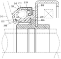
一方、図10に、特許文献2に記載されたクラッチレリーズ軸受とほぼ同一の構成のクラッチレリーズ軸受210の部分断面図を示す。図10に示すように、このクラッチレリーズ軸受210では、外輪220との間に複数の玉(転動体)214が転動可能に配置される内輪230の内周には自動調心用の弾性スリーブ260が固着されている。そして、内輪230の一端部において弾性スリーブ260からシール部材262が突設形成されており、シール部材262の二股に分岐した先端を外輪220の鍔部222の内面に摺接させて、外輪220と内輪230の間の隙間を塞ぐ構成とされている。また、軸方向の他端では、内輪230にスリンガ270を外嵌め固定し、外輪に取付けたオイルシール272の先端をスリンガ270に軸受外方から摺接させて、外輪220と内輪230の間の隙間を塞ぐ構成とされている。よって、クラッチレリーズ軸受210は、潤滑油が漏れにくく泥水が侵入しにくい構造であるため、良好な潤滑性と耐水性を維持できると考えられる。
しかしながら、図10に示したクラッチレリーズ軸受210では、シール部材242が外輪220の鍔部222の内面に接触する構造であるため、外輪220の回転による鍔部222とシール部材242との摩擦によりトルク損失が生じるという問題がある。
そこで、本発明が解決しようとする課題は、耐水性を向上させるとともに、トルク損失を低減させたクラッチレリーズ軸受を提供することにある。
上記課題を解決するため、本発明にかかるクラッチレリーズ軸受は次の手段をとる。
まず、本発明の第1の発明は、外輪と、内輪と、外輪と内輪の間に転動可能に配置された複数の転動体と、転動体を回動自在に保持する保持器を備え、
前記外輪の一側端部には径方向内方に延びる外輪鍔部が形成されると共に、該外輪鍔部の軸受外部の側面はクラッチ機構の回転部材が接触する接触面とされ、該外輪鍔部が形成された一側と軸線方向の反対側には、該外輪に固定されたシール部材が配設されており、該シール部材の径方向内方の先端に形成されたシールリップが該内輪の外周面に摺接する構成とされているクラッチレリーズ軸受であって、
前記シール部材の軸受外方には前記内輪と一体的とされた円環状の相手部材が配設されており、該シール部材の軸受外方の側面に軸受外方に向けて延設され相手部材の径方向外方に向けて延びるアキシアルリップが形成されており、該アキシアルリップは該相手部材と非接触の近接状態でラビリンスを形成し、該アキシアルリップの該シール部材への付け根部に径方向外方に開口した溝が形成されていることを特徴とするクラッチレリーズ軸受。
この第1の発明によれば、シール部材のアキシアルリップが相手部材の径方向外方に向けて延設され、アキシアルリップと相手部材の隙間を覆っている。よって、泥水が径方向外方から軸受にかかっても、アキシアルリップに覆われたシール部材と相手部材の間の隙間に泥水が直接入り込むことが抑止される。そして、アキシアルリップのシール部材への付け根部に径方向外方に開口した溝が形成されているので、アキシアルリップにかかった泥水は、アキシアルリップの付け根部の溝から、円周方向に流れて、軸受の下方から排水される。また、アキシアルリップは相手部材と非接触の近接状態でラビリンスを形成しているので、アキシアルリップと相手部材の隙間からの泥水の軸受内部への侵入が抑止される。
よって、クラッチレリーズ軸受の耐水性が向上する。
まず、本発明の第1の発明は、外輪と、内輪と、外輪と内輪の間に転動可能に配置された複数の転動体と、転動体を回動自在に保持する保持器を備え、
前記外輪の一側端部には径方向内方に延びる外輪鍔部が形成されると共に、該外輪鍔部の軸受外部の側面はクラッチ機構の回転部材が接触する接触面とされ、該外輪鍔部が形成された一側と軸線方向の反対側には、該外輪に固定されたシール部材が配設されており、該シール部材の径方向内方の先端に形成されたシールリップが該内輪の外周面に摺接する構成とされているクラッチレリーズ軸受であって、
前記シール部材の軸受外方には前記内輪と一体的とされた円環状の相手部材が配設されており、該シール部材の軸受外方の側面に軸受外方に向けて延設され相手部材の径方向外方に向けて延びるアキシアルリップが形成されており、該アキシアルリップは該相手部材と非接触の近接状態でラビリンスを形成し、該アキシアルリップの該シール部材への付け根部に径方向外方に開口した溝が形成されていることを特徴とするクラッチレリーズ軸受。
この第1の発明によれば、シール部材のアキシアルリップが相手部材の径方向外方に向けて延設され、アキシアルリップと相手部材の隙間を覆っている。よって、泥水が径方向外方から軸受にかかっても、アキシアルリップに覆われたシール部材と相手部材の間の隙間に泥水が直接入り込むことが抑止される。そして、アキシアルリップのシール部材への付け根部に径方向外方に開口した溝が形成されているので、アキシアルリップにかかった泥水は、アキシアルリップの付け根部の溝から、円周方向に流れて、軸受の下方から排水される。また、アキシアルリップは相手部材と非接触の近接状態でラビリンスを形成しているので、アキシアルリップと相手部材の隙間からの泥水の軸受内部への侵入が抑止される。
よって、クラッチレリーズ軸受の耐水性が向上する。
次に、本発明の第2の発明は、上記第1の発明に係るクラッチレリーズ軸受であって、
前記シール部材のシールリップが前記内輪の外径面に摺接する位置の軸受外方位置で、該内輪の外径面に溝が形成されていることを特徴とする。
この第2の発明によれば、シール部材と相手部材の隙間に泥水が入り内輪の外径面に達した場合でも、泥水は、内輪の外径面のシールリップが摺接する位置から軸受外方位置に形成された溝を伝って円周方向に流れて、軸受の下方から排水される。よって、内輪にシールリップが摺接する位置から軸受内部への泥水の侵入が抑止される。
前記シール部材のシールリップが前記内輪の外径面に摺接する位置の軸受外方位置で、該内輪の外径面に溝が形成されていることを特徴とする。
この第2の発明によれば、シール部材と相手部材の隙間に泥水が入り内輪の外径面に達した場合でも、泥水は、内輪の外径面のシールリップが摺接する位置から軸受外方位置に形成された溝を伝って円周方向に流れて、軸受の下方から排水される。よって、内輪にシールリップが摺接する位置から軸受内部への泥水の侵入が抑止される。
次に、本発明の第3の発明は、上記第1の発明または第2の発明に係るクラッチレリーズ軸受であって、
前記シール部材の軸受外方の側面の前記アキシアルリップよりも径方向内方位置で、該シール部材の軸受外方の側面に凹部または凸部が形成されていることを特徴とする。
この第3の発明によれば、シール部材は外輪に固定され外輪と共に回転するので、シール部材の軸受外方の側面に形成された凹部または凸部が回転し、シール部材と相手部材の隙間に円周方向の空気の流れが生じる。そのため、アキシアルリップと相手部材の隙間からシール部材と相手部材の隙間に泥水が入り込んだ場合は、泥水は遠心力により軸受の径方向外方へ導かれる。よって、シール部材と相手部材の隙間から径方向内方への泥水の浸入が抑止される。
前記シール部材の軸受外方の側面の前記アキシアルリップよりも径方向内方位置で、該シール部材の軸受外方の側面に凹部または凸部が形成されていることを特徴とする。
この第3の発明によれば、シール部材は外輪に固定され外輪と共に回転するので、シール部材の軸受外方の側面に形成された凹部または凸部が回転し、シール部材と相手部材の隙間に円周方向の空気の流れが生じる。そのため、アキシアルリップと相手部材の隙間からシール部材と相手部材の隙間に泥水が入り込んだ場合は、泥水は遠心力により軸受の径方向外方へ導かれる。よって、シール部材と相手部材の隙間から径方向内方への泥水の浸入が抑止される。
次に、本発明の第4の発明は、上記第1の発明~第3の発明のいずれかの発明に係るクラッチレリーズ軸受であって、
前記相手部材と前記シール部材が非接触の近接状態でラビリンスを形成することを特徴とする。
この第4の発明によれば、シール部材と相手部材がラビリンスを形成するので、アキシアルリップと相手部材の隙間から泥水がシール部材と相手部材の間に侵入した場合でも、シール部材と相手部材の隙間から径方向内方への泥水の浸入が抑止される。
前記相手部材と前記シール部材が非接触の近接状態でラビリンスを形成することを特徴とする。
この第4の発明によれば、シール部材と相手部材がラビリンスを形成するので、アキシアルリップと相手部材の隙間から泥水がシール部材と相手部材の間に侵入した場合でも、シール部材と相手部材の隙間から径方向内方への泥水の浸入が抑止される。
次に、本発明の第5の発明は、上記第1の発明~第3の発明のいずれかの発明に係るクラッチレリーズ軸受であって、
前記相手部材はクラッチレリーズ軸受の調心を円滑におこなうためのガイドであって、前記シール部材と該ガイドの間に前記内輪に固定され径方向外方に延在するスリンガが配設されており、該シール部材と該スリンガは軸線方向で非接触の近接状態でラビリンスを形成し、該スリンガと該ガイドは軸線方向でラビリンスが形成されない離間状態とされていることを特徴とする。
この第5の発明によれば、スリンガとガイドは軸線方向で離間状態であってラビリンスが形成されないので、泥水の侵入が容易である。一方、シール部材とスリンガの間はラビリンスが形成されているので泥水の浸入が困難である。よって、アキシアルリップとガイドの隙間から泥水がシール部材とガイドの間に侵入した場合でも、泥水は、スリンガとガイドの隙間でトラップされ、シール部材とスリンガの間へは侵入しにくい。よって、シール部材とスリンガの隙間の径方向内方への泥水の浸入が抑止される。
前記相手部材はクラッチレリーズ軸受の調心を円滑におこなうためのガイドであって、前記シール部材と該ガイドの間に前記内輪に固定され径方向外方に延在するスリンガが配設されており、該シール部材と該スリンガは軸線方向で非接触の近接状態でラビリンスを形成し、該スリンガと該ガイドは軸線方向でラビリンスが形成されない離間状態とされていることを特徴とする。
この第5の発明によれば、スリンガとガイドは軸線方向で離間状態であってラビリンスが形成されないので、泥水の侵入が容易である。一方、シール部材とスリンガの間はラビリンスが形成されているので泥水の浸入が困難である。よって、アキシアルリップとガイドの隙間から泥水がシール部材とガイドの間に侵入した場合でも、泥水は、スリンガとガイドの隙間でトラップされ、シール部材とスリンガの間へは侵入しにくい。よって、シール部材とスリンガの隙間の径方向内方への泥水の浸入が抑止される。
次に、本発明の第6の発明は、上記第1の発明~第3の発明のいずれかの発明に係るクラッチレリーズ軸受であって、
前記相手部材は前記内輪から径方向外方に延設された内輪鍔部であって、該内輪鍔部には軸受内方に向かって拡径する突起部が形成されており、該突起部の先端はシール部材の軸受外方の側面に非接触の近接状態とされていることを特徴とする。
この第6の発明によれば、内輪鍔部に形成された突起部の先端はシール部材の軸受外方の側面に非接触の近接状態とされラビリンスを形成するので、シール部材と内輪鍔部の間に介在する泥水の径方向内方への侵入が抑止される。また、内輪鍔部に形成された突起部は軸受内方に向かって拡径しており、突起部の付け根には溝が形成されるため、突起部の径方向外方に介在する泥水は突起部の付け根の溝に集まり、円周方向に流れて軸受下方へ排水される。
前記相手部材は前記内輪から径方向外方に延設された内輪鍔部であって、該内輪鍔部には軸受内方に向かって拡径する突起部が形成されており、該突起部の先端はシール部材の軸受外方の側面に非接触の近接状態とされていることを特徴とする。
この第6の発明によれば、内輪鍔部に形成された突起部の先端はシール部材の軸受外方の側面に非接触の近接状態とされラビリンスを形成するので、シール部材と内輪鍔部の間に介在する泥水の径方向内方への侵入が抑止される。また、内輪鍔部に形成された突起部は軸受内方に向かって拡径しており、突起部の付け根には溝が形成されるため、突起部の径方向外方に介在する泥水は突起部の付け根の溝に集まり、円周方向に流れて軸受下方へ排水される。
また、本発明の第7の発明は、外輪と、内輪と、外輪と内輪の間に転動可能に配置された複数の転動体とを備え、
前記外輪の一側端部には径方向内方に延びる外輪鍔部が形成されると共に、該外輪鍔部の軸受外部の側面はダイヤフラムスプリングが接触する接触面とされ、該外輪鍔部が形成された一側と同じ側の前記内輪の一側端部には、径方向内方に延びる内輪鍔部が前記外輪鍔部と所定の間隔をおいて形成された、クラッチレリーズ軸受であって、
前記内輪の一側端部から内輪鍔部にかけて、シール部材が配設されており、該シール部材には、前記外輪鍔部の先端と非接触の近接状態として配設されるアキシアルリップと、前記外輪鍔部の軸受内部の側面と非接触の近接状態として配設されるシールリップが形成されていることを特徴とする。
前記外輪の一側端部には径方向内方に延びる外輪鍔部が形成されると共に、該外輪鍔部の軸受外部の側面はダイヤフラムスプリングが接触する接触面とされ、該外輪鍔部が形成された一側と同じ側の前記内輪の一側端部には、径方向内方に延びる内輪鍔部が前記外輪鍔部と所定の間隔をおいて形成された、クラッチレリーズ軸受であって、
前記内輪の一側端部から内輪鍔部にかけて、シール部材が配設されており、該シール部材には、前記外輪鍔部の先端と非接触の近接状態として配設されるアキシアルリップと、前記外輪鍔部の軸受内部の側面と非接触の近接状態として配設されるシールリップが形成されていることを特徴とする。
この第7の発明によれば、外輪鍔部の先端とシール部材のアキシアルリップとの間でラビリンスを形成するため、泥水などの異物のクラッチレリーズ軸受の内部への侵入を抑止することが出来る。また、外輪鍔部の軸受内方の側面とシール部材のシールリップがラビリンスを形成するため、グリース等の潤滑油の軸受内部からの流出を抑止することが出来る。
そして、シール部材のアキシアルリップ及びシールリップはいずれも外輪に非接触であるため、接触タイプに比べて、トルクの損失を低減させることが出来る。
よって、良好な潤滑性と耐水性を維持させることができ、かつ、トルク損失を低減させたクラッチレリーズ軸受を提供することすることができる。
そして、シール部材のアキシアルリップ及びシールリップはいずれも外輪に非接触であるため、接触タイプに比べて、トルクの損失を低減させることが出来る。
よって、良好な潤滑性と耐水性を維持させることができ、かつ、トルク損失を低減させたクラッチレリーズ軸受を提供することすることができる。
次に、本発明の第8の発明は、上記第1の発明に係るクラッチレリーズ軸受であって、前記外輪鍔部の先端の軸受外方に、軸受内方から軸受外方に向かって径方向内方から径方向外方へ傾斜する面取りがなされていることを特徴とする。
この第8の発明によれば、外輪鍔部の先端の軸受外方に軸受内方から軸受外方に向かって径方向内方から径方向外方へ傾斜する面取りがなされている。よって、外輪鍔部の先端の軸受外方の面取りされた部位の近くに介在する泥水等の異物は、外輪の回転による遠心力により軸受の径方向外方かつ軸受外方に誘導されるため、クラッチレリーズ軸受の防水性能が更に向上する。
この第8の発明によれば、外輪鍔部の先端の軸受外方に軸受内方から軸受外方に向かって径方向内方から径方向外方へ傾斜する面取りがなされている。よって、外輪鍔部の先端の軸受外方の面取りされた部位の近くに介在する泥水等の異物は、外輪の回転による遠心力により軸受の径方向外方かつ軸受外方に誘導されるため、クラッチレリーズ軸受の防水性能が更に向上する。
次に、本発明の第9の発明は、上記第1の発明又は第2の発明に係るクラッチレリーズ軸受であって、前記外輪鍔部の先端の、前記シール部材のアキシアルリップに対して非接触の近接状態とされる範囲が、軸線方向で狭小な幅とされていることを特徴とする。
この第9の発明によれば、外輪鍔部の先端とシール部材のアキシアルリップが非接触の近接状態となる軸線方向の幅が狭くなるため、ダイヤフラムスプリングからのトルク伝達時に外輪鍔部が変形して外輪鍔部の先端がアキシアルリップに接触した場合でも、接触する幅が狭く、接触抵抗によるトルク損失を低く抑えることができる。
この第9の発明によれば、外輪鍔部の先端とシール部材のアキシアルリップが非接触の近接状態となる軸線方向の幅が狭くなるため、ダイヤフラムスプリングからのトルク伝達時に外輪鍔部が変形して外輪鍔部の先端がアキシアルリップに接触した場合でも、接触する幅が狭く、接触抵抗によるトルク損失を低く抑えることができる。
上述の本発明の各発明によれば、次の効果が得られる。
まず、上述の第1の発明によれば、泥水が径方向外方から軸受にかかっても、アキシアルリップに覆われたシール部材と相手部材の間の隙間に泥水が直接入り込むことが抑止される。そして、アキシアルリップにかかった泥水は、アキシアルリップの付け根部の径方向外方に開口した溝から、円周方向に流れて、軸受の下方から排水される。また、アキシアルリップと相手部材がラビリンスを形成するので、アキシアルリップと相手部材の隙間からの泥水の軸受内部への侵入が抑止される。よって、クラッチレリーズ軸受の耐水性が向上し、良好な潤滑性と耐水性を維持することができる。
次に上述の第2の発明によれば、シール部材と相手部材の隙間に泥水が入り内輪の外径面に達した場合でも、泥水は、内輪の外径面のシールリップが摺接する位置の軸受外方位置に形成された溝を伝って円周方向に流れて、軸受の下方から排水される。よって、内輪にシールリップが摺接する位置から軸受内部への泥水の侵入が抑止される。
次に上述の第3の発明によれば、シール部材の軸受外方の側面に形成された凹部または凸部が回転するため、アキシアルリップと相手部材の隙間からシール部材と相手部材の隙間に泥水が入り込んだ場合は、泥水は遠心力により軸受の径方向外方へ導かれる。よって、アキシアルリップと相手部材の隙間から泥水がシール部材と相手部材の間に侵入した場合でも、シール部材と相手部材の間の径方向内方への泥水の浸入が抑止される。
次に上述の第4の発明によれば、シール部材と相手部材がラビリンスを形成するので、アキシアルリップと相手部材の隙間から泥水がシール部材と相手部材の間に侵入した場合でも、シール部材と相手部材の隙間から径方向内方への泥水の浸入が抑止される。
次に上述の第5の発明によれば、アキシアルリップとガイドの隙間から泥水がシール部材とガイドの間に侵入した場合でも、泥水は、スリンガとガイドの隙間でトラップされ、シール部材とスリンガの間へは侵入しにくい。よって、シール部材とスリンガの隙間の径方向内方への泥水の浸入が抑止される。
次に上述の第6の発明によれば、内輪鍔部に形成された突起部とシール部材がラビリンスを形成するので、シール部材と内輪鍔部の間に介在する泥水の径方向内方への侵入が抑止される。また、内輪鍔部に形成された突起部は軸受内方に向かって拡径しており、突起部の付け根には溝が形成されるため、突起部の径方向外方に介在する泥水は突起部の付け根の溝に集まり、円周方向に流れて軸受下方へ排水される。
まず、上述の第1の発明によれば、泥水が径方向外方から軸受にかかっても、アキシアルリップに覆われたシール部材と相手部材の間の隙間に泥水が直接入り込むことが抑止される。そして、アキシアルリップにかかった泥水は、アキシアルリップの付け根部の径方向外方に開口した溝から、円周方向に流れて、軸受の下方から排水される。また、アキシアルリップと相手部材がラビリンスを形成するので、アキシアルリップと相手部材の隙間からの泥水の軸受内部への侵入が抑止される。よって、クラッチレリーズ軸受の耐水性が向上し、良好な潤滑性と耐水性を維持することができる。
次に上述の第2の発明によれば、シール部材と相手部材の隙間に泥水が入り内輪の外径面に達した場合でも、泥水は、内輪の外径面のシールリップが摺接する位置の軸受外方位置に形成された溝を伝って円周方向に流れて、軸受の下方から排水される。よって、内輪にシールリップが摺接する位置から軸受内部への泥水の侵入が抑止される。
次に上述の第3の発明によれば、シール部材の軸受外方の側面に形成された凹部または凸部が回転するため、アキシアルリップと相手部材の隙間からシール部材と相手部材の隙間に泥水が入り込んだ場合は、泥水は遠心力により軸受の径方向外方へ導かれる。よって、アキシアルリップと相手部材の隙間から泥水がシール部材と相手部材の間に侵入した場合でも、シール部材と相手部材の間の径方向内方への泥水の浸入が抑止される。
次に上述の第4の発明によれば、シール部材と相手部材がラビリンスを形成するので、アキシアルリップと相手部材の隙間から泥水がシール部材と相手部材の間に侵入した場合でも、シール部材と相手部材の隙間から径方向内方への泥水の浸入が抑止される。
次に上述の第5の発明によれば、アキシアルリップとガイドの隙間から泥水がシール部材とガイドの間に侵入した場合でも、泥水は、スリンガとガイドの隙間でトラップされ、シール部材とスリンガの間へは侵入しにくい。よって、シール部材とスリンガの隙間の径方向内方への泥水の浸入が抑止される。
次に上述の第6の発明によれば、内輪鍔部に形成された突起部とシール部材がラビリンスを形成するので、シール部材と内輪鍔部の間に介在する泥水の径方向内方への侵入が抑止される。また、内輪鍔部に形成された突起部は軸受内方に向かって拡径しており、突起部の付け根には溝が形成されるため、突起部の径方向外方に介在する泥水は突起部の付け根の溝に集まり、円周方向に流れて軸受下方へ排水される。
まず、上述の第7の発明によれば、外輪鍔部の先端とシール部材のアキシアルリップとの間でラビリンスを形成するため、泥水などの異物のクラッチレリーズ軸受の内部への侵入を抑止することが出来る。また、外輪の鍔部の軸受内方の側面とシール部材のシールリップがラビリンスを形成するため、グリース等の潤滑油の軸受内部からの流出を抑止することが出来る。そして、シール部材のアキシアルリップ及びシールリップはいずれも外輪に非接触であるため、接触タイプに比べて、トルクの損失を低減させることが出来る。よって、良好な潤滑性と耐水性を維持することができ、かつ、トルク損失を低減させたクラッチレリーズ軸受を提供することすることができる。
次に上述の第8の発明によれば、外輪鍔部の先端の軸受外方の面取りされた部位の近くに介在する泥水等の異物は、遠心力により軸受の径方向外方かつ軸受外方に誘導されるため、クラッチレリーズ軸受の防水性能が更に向上する。
次に上述の第9の発明によれば、ダイヤフラムスプリングからのトルク伝達時に外輪鍔部が変形して外輪鍔部の先端がアキシアルリップに接触した場合でも、接触する幅が狭く、接触抵抗によるトルク損失を低く抑えることができ、良好な潤滑性と耐水性を維持することができる。
次に上述の第8の発明によれば、外輪鍔部の先端の軸受外方の面取りされた部位の近くに介在する泥水等の異物は、遠心力により軸受の径方向外方かつ軸受外方に誘導されるため、クラッチレリーズ軸受の防水性能が更に向上する。
次に上述の第9の発明によれば、ダイヤフラムスプリングからのトルク伝達時に外輪鍔部が変形して外輪鍔部の先端がアキシアルリップに接触した場合でも、接触する幅が狭く、接触抵抗によるトルク損失を低く抑えることができ、良好な潤滑性と耐水性を維持することができる。
以下、本発明を実施するための最良の形態について実施例にしたがって説明する。
まず、実施例1について説明する。図1に本発明の実施例1におけるクラッチレリーズ軸受10の部分断面図を示す。クラッチレリーズ軸受10は外輪20と、内輪30と、外輪20と内輪30の間に転動可能に配置された複数の玉(転動体)14と、玉14を回動自在に保持する保持器16とを備えた外輪回転タイプのクラッチレリーズ軸受である。そして、外輪20の一側端部には径方向内方に延びる外輪鍔部22が形成されると共に、外輪鍔部22の軸方向外方の側面はダイヤフラムスプリング12が接触する接触面24とされている。このダイヤフラムスプリング12が本発明のクラッチ機構の回転部材である。なお、外輪20および内輪30はプレス加工により形成される。
そして、外輪鍔部22が形成された一側と軸線方向の反対側には、外輪20に外嵌め固定された第1シール部材40が配設されている。この第1シール部材40が本発明のシール部材である。第1シール部材40は、断面が略L字の円環状の部材であって、金属製の芯金41にゴム製の被覆部42が装着されている。そして、第1シール部材40の径方向内方の先端には、被覆部42と一体でシールリップ44が形成されており、シールリップ44は、内輪30の外径面32に摺接する構成とされている。
そして、第1シール部材40の軸受外方にはクラッチレリーズ軸受10の軸線方向移動時の調心を円滑化させるための円環状のガイド50が配設されている。このガイド50が本発明の相手部材である。そして、ガイド50の内径側に形成されたフランジ52が内輪30の内径側に圧入され、ガイド50と内輪30が一体化されている。そして、第1シール部材40の軸受外方の側面には、軸受外方に向けて延設され、ガイド50の径方向外方まで延びたアキシアルリップ46が形成されている。そして、アキシアルリップ46はガイド50と非接触の近接状態とされラビリンスを形成している。そして、アキシアルリップ46の外径面は軸線方向に平行とされ、アキシアルリップ46の第1シール部材40への付け根部には径方向外方に開口した溝47が形成されている。
なお、実施例1では第1シール部材40の被覆部42、シールリップ44及びアキシアルリップ46をゴム製としてるが、これらは軟質樹脂製としても良い。
なお、実施例1では第1シール部材40の被覆部42、シールリップ44及びアキシアルリップ46をゴム製としてるが、これらは軟質樹脂製としても良い。
そして、第1シール部材40とガイド50は軸線方向で非接触の近接状態とされ、ラビリンスを形成している。
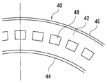
そして、第1シール部材40の軸受外方の側面のアキシアルリップ46よりも径方向内方位置で、第1シール部材40の軸受外方の側面の被覆部42から矩形に肉抜きをした凹部48が形成されている。図2に、第1シール部材40を軸受外方から見た部分平面図を示す。図2に示すとおり、凹部48は同心円上にほぼ等間隔で形成されている。
そして、図1に示したとおり、外輪鍔部22が形成された一側と同じ側の内輪30の一側端部には、径方向内方に延びる内輪鍔部36が外輪鍔部22と所定の間隔をおいて形成されている。そして、内輪30には、内輪鍔部36から軸受内方に、軸線方向に平行な円筒状の筒状部34が形成されている。
そして、内輪30の筒状部34から内輪鍔部36に跨って、第2シール部材60が配設されている。第2シール部材60は、金属製の芯金62にゴム製の被覆部64を装着した円環状の部材であって、内輪30に対して内輪鍔部36が形成された側から圧入され、内輪30の筒状部34に形成された係合溝35に係合して内輪30に固定されている。そして、第2シール部材60は、被覆部64と一体で形成されたゴム製のアキシアルリップ66と、被覆部64と一体で形成されたゴム製のシールリップ68を備えている。
そして、アキシアルリップ66は、外輪鍔部22の先端26と狭小な間隔で近接し外輪20と非接触となる構成とされ、シールリップ68は、外輪鍔部22の軸受内方の側面と狭小な間隔で近接し外輪鍔部22と非接触となる構成とされている。
そして、内輪30の筒状部34から内輪鍔部36に跨って、第2シール部材60が配設されている。第2シール部材60は、金属製の芯金62にゴム製の被覆部64を装着した円環状の部材であって、内輪30に対して内輪鍔部36が形成された側から圧入され、内輪30の筒状部34に形成された係合溝35に係合して内輪30に固定されている。そして、第2シール部材60は、被覆部64と一体で形成されたゴム製のアキシアルリップ66と、被覆部64と一体で形成されたゴム製のシールリップ68を備えている。
そして、アキシアルリップ66は、外輪鍔部22の先端26と狭小な間隔で近接し外輪20と非接触となる構成とされ、シールリップ68は、外輪鍔部22の軸受内方の側面と狭小な間隔で近接し外輪鍔部22と非接触となる構成とされている。
この実施例1によれば、第1シール部材40のアキシアルリップ46がガイド50の径方向外方まで延設されている。よって、泥水が径方向外方からクラッチレリーズ軸受10にかかっても、第1シール部材40のアキシアルリップ46に覆われた第1シール部材40とガイド50の間の隙間に泥水が直接入り込むことが抑止される。そして、アキシアルリップ46の第1シール部材40への付け根部に径方向外方に開口した溝47が形成されているので、アキシアルリップ46にかかった泥水は、アキシアルリップ46の付け根部の溝47から、円周方向に流れて、クラッチレリーズ軸受10の下方から排水される。そして、アキシアルリップ46はガイド50と非接触の近接状態でラビリンスを形成しているので、アキシアルリップ46とガイド50の隙間から軸受内部への泥水の侵入が抑止される。
そして、実施例1によれば、第1シール部材40とガイド50は軸線方向で非接触の近接状態とされ、ラビリンスを形成しているので、アキシアルリップ46とガイド50の隙間から泥水が第1シール部材40とガイド50の間に侵入した場合でも、第1シール部材40とガイド50の隙間から軸受の径方向内方への泥水の浸入が抑止される。
また、実施例1によれば、第1シール部材40は外輪20に固定され外輪20と共に回転するので、第1シール部材40の軸受外方の側面に形成された凹部48が回転して、第1シール部材40とガイド50の隙間に円周方向の空気の流れが生じる。そのため、アキシアルリップ46とガイド50の隙間から第1シール部材40とガイド50の隙間に泥水が入り込んだ場合は、泥水は遠心力により軸受の径方向外方へ導かれる。よって、第1シール部材40とガイド50の隙間から軸受の径方向内方への泥水の浸入が抑止される。
よって、実施例1によれば、クラッチレリーズ軸受の耐水性が向上する。
よって、実施例1によれば、クラッチレリーズ軸受の耐水性が向上する。
実施例1では、第1シール部材40の側面に凹部48を設けているが、凹部48の代わりに凸部を設けて円周方向の空気の流れを生じさせる構成としてもよい。また、実施例1では、第1シール部材40のアキシアルリップ46の外径面を軸線方向と平行としているが、アキシアルリップ46の外径面を軸受外方に向かって拡径させてもよい。アキシアルリップ46の外径面を軸受外方に向かって拡径する構成とすれば、アキシアルリップ46の外径面に付着した泥水が溝47に集まりやすくなる。
次に、実施例2について説明する。図3に本発明の実施例2におけるクラッチレリーズ軸受10Aの部分断面図を示す。クラッチレリーズ軸受10Aは、実施例1のクラッチレリーズ軸受10と比べて、第1シール部材40とガイド50の間に径方向外方に延在する金属製のスリンガ54が配設されている点、及び第1シール部材40の軸受外方の側面に凹部48が形成されていない点に特徴がある。
スリンガ54は、スリンガ54の内径部56をガイド50のフランジ52に外嵌めした状態で、ガイド50のフランジ52を内輪30の内径面に圧入することにより、内輪30及びガイド50と一体化されている。
そして、スリンガ54は、内径側では内輪30の端部38とガイド50の軸受内方の側面で挟まれた状態とされている。そして、内輪30の外径面32よりも径方向外方で軸受内方へ傾斜した状態とされてガイド50の側面から離間し、外径側では軸線方向と垂直とされている。そして、スリンガ54の径方向外方の先端は第1シール部材40のアキシアルリップ46と非接触とされている。そして、第1シール部材40とスリンガ54は軸線方向で非接触の近接状態でラビリンスを形成しており、スリンガ54とガイド50は軸線方向でラビリンスが形成されない離間状態とされている。
スリンガ54は、スリンガ54の内径部56をガイド50のフランジ52に外嵌めした状態で、ガイド50のフランジ52を内輪30の内径面に圧入することにより、内輪30及びガイド50と一体化されている。
そして、スリンガ54は、内径側では内輪30の端部38とガイド50の軸受内方の側面で挟まれた状態とされている。そして、内輪30の外径面32よりも径方向外方で軸受内方へ傾斜した状態とされてガイド50の側面から離間し、外径側では軸線方向と垂直とされている。そして、スリンガ54の径方向外方の先端は第1シール部材40のアキシアルリップ46と非接触とされている。そして、第1シール部材40とスリンガ54は軸線方向で非接触の近接状態でラビリンスを形成しており、スリンガ54とガイド50は軸線方向でラビリンスが形成されない離間状態とされている。
そして、第1シール部材40径方向内方の先端に形成されたシールリップ44は、肉厚が薄く足が長く剛性の低い形状とされ、内輪30の外径面32に軽接触とされて、低トルク化が図られている。
なお、クラッチレリーズ軸受10Aの他の構成は、実施例1のクラッチレリーズ軸受10と同様であるので、同じ符号を付して、詳細な説明は省略する。
なお、クラッチレリーズ軸受10Aの他の構成は、実施例1のクラッチレリーズ軸受10と同様であるので、同じ符号を付して、詳細な説明は省略する。
この実施例2によれば、第1シール部材40のアキシアルリップ46がガイド50の径方向外方まで延設されている。よって、泥水が径方向外方からクラッチレリーズ軸受10Aにかかっても、第1シール部材40のアキシアルリップ46に覆われた第1シール部材40とガイド50の間の隙間に泥水が直接入り込むことが抑止される。そして、アキシアルリップ46の第1シール部材40への付け根部に径方向外方に開口した溝47が形成されているので、アキシアルリップ46にかかった泥水は、アキシアルリップ46の付け根の溝47から、円周方向に流れて、クラッチレリーズ軸受10Aの下方から排水される。
そして、アキシアルリップ46はガイド50と非接触の近接状態でラビリンスを形成しているので、アキシアルリップ46とガイド50の隙間から軸受の径方向内方への泥水の侵入が抑止される。
そして、アキシアルリップ46はガイド50と非接触の近接状態でラビリンスを形成しているので、アキシアルリップ46とガイド50の隙間から軸受の径方向内方への泥水の侵入が抑止される。
そして、実施例2によれば、スリンガ54とガイド50の間は軸線方向で離間状態であってラビリンスが形成されないので、泥水の侵入が容易である。一方、第1シール部材40とスリンガ54の間はラビリンスが形成されているので泥水の浸入が困難である。よって、アキシアルリップ46とガイド50の隙間から泥水が第1シール部材40とガイド50の間に侵入した場合でも、泥水は、スリンガ54とガイド50の隙間でトラップされ、第1シール部材40とスリンガ54の間へは侵入しにくい。そして、スリンガ54とガイド50の隙間でトラップされた泥水は、円周方向に流れて、クラッチレリーズ軸受10Aの下方から排水される。よって、第1シール部材40とスリンガ54の隙間から軸受の径方向内方への泥水の浸入が抑止される。
実施例2では、第1シール部材40の軸受外方の側面に凹部48を形成しない構成としたが、実施例1と同様に第1シール部材40の軸受外方の側面に凹部48を形成する構成としてもよい。また、凹部48の代わりに凸部を設けて円周方向の空気の流れを生じさせる構成としてもよい。
そして、アキシアルリップ46の外径面を軸受外方に向かって拡径させてもよい。アキシアルリップ46の外径面を軸受外方に向かって拡径する構成とすれば、アキシアルリップ46の外径面に付着した泥水がアキシアルリップ46の付け根部の溝47に集まりやすくなる。
よって、実施例2によれば、クラッチレリーズ軸受の耐水性が向上し、グリースの劣化が抑止され、軸受の短寿命化が抑止される。また、グリースの劣化の抑止により、異音の発生が抑止される。
そして、アキシアルリップ46の外径面を軸受外方に向かって拡径させてもよい。アキシアルリップ46の外径面を軸受外方に向かって拡径する構成とすれば、アキシアルリップ46の外径面に付着した泥水がアキシアルリップ46の付け根部の溝47に集まりやすくなる。
よって、実施例2によれば、クラッチレリーズ軸受の耐水性が向上し、グリースの劣化が抑止され、軸受の短寿命化が抑止される。また、グリースの劣化の抑止により、異音の発生が抑止される。
最後に、実施例3について説明する。図4に本発明の実施例3におけるクラッチレリーズ軸受110の部分断面図を示す。クラッチレリーズ軸受110は、外輪120と、内輪130と、外輪120と内輪130の間に転動可能に配置された複数の玉(転動体)114と、保持器116とを備えた外輪回転タイプのクラッチレリーズ軸受である。そして、外輪120の一端部には径方向内方に延びる外輪鍔部122が形成されると共に、外輪鍔部122の軸受外方の側面はダイヤフラムスプリング112が接触する接触面124とされている。このダイヤフラムスプリング112が本発明のクラッチ機構の回転部材である。なお、外輪120および内輪130はプレス加工により形成される。
そして、外輪鍔部122が形成された一側と軸線方向の反対側には、外輪120に外嵌め固定された第1シール部材140が配設されている。この第1シール部材140が本発明のシール部材である。第1シール部材140は、円環状の部材であって、金属製の芯金141にゴム製の被覆部142が装着されている。そして、第1シール部材140の径方向内方の先端には、被覆部142と一体でシールリップ144が形成されており、シールリップ144は、内輪130の外径面132に摺接する構成とされている。そして第1シール部材140のシールリップ144が内輪130の外径面132に摺接する位置から軸受外方位置で、内輪130の外径面132に溝136が形成されている。
そして、第1シール部材140の軸受外方には、内輪130の端部を径方向外方に延設した内輪鍔部134が、第1シール部材140と非接触の状態で配設されている。この内輪鍔部134が本発明の相手部材である。
そして、第1シール部材140の軸受外方の側面には、軸受外方に向けて拡径して延設され、内輪鍔部134の径方向外方まで延びたアキシアルリップ146が形成されており、アキシアルリップ146は内輪鍔部134と非接触の近接状態とされラビリンスを形成している。そして、アキシアルリップ146が軸受外方に向けて拡径する構成のため、アキシアルリップ146の第1シール部材140への付け根部の径方向外方には溝147が形成される。
そして、内輪鍔部134には軸受内方に向かって拡径する突起部138が切り起こしにより形成されており、突起部138の先端は第1シール部材140の軸受外方の側面に非接触の近接状態とされている。
そして、第1シール部材140の軸受外方の側面には、軸受外方に向けて拡径して延設され、内輪鍔部134の径方向外方まで延びたアキシアルリップ146が形成されており、アキシアルリップ146は内輪鍔部134と非接触の近接状態とされラビリンスを形成している。そして、アキシアルリップ146が軸受外方に向けて拡径する構成のため、アキシアルリップ146の第1シール部材140への付け根部の径方向外方には溝147が形成される。
そして、内輪鍔部134には軸受内方に向かって拡径する突起部138が切り起こしにより形成されており、突起部138の先端は第1シール部材140の軸受外方の側面に非接触の近接状態とされている。
そして、内輪130の内周には自動調心用の弾性スリーブ150が固着されており、外輪鍔部122が形成された側と同じ側の内輪130の一端部において弾性スリーブ150からシールリップ152が突設形成され、シールリップ152の二股に分岐した先端が外輪鍔部122の内面に対して軽接触の接触状態とされている。
この実施例3によれば、第1シール部材140のアキシアルリップ146が内輪鍔部134の径方向外方まで延設されている。よって、泥水が径方向外方からクラッチレリーズ軸受110にかかっても、第1シール部材140のアキシアルリップ146に覆われた第1シール部材140と内輪鍔部134の間の隙間に泥水が直接入り込むことが抑止される。そして、アキシアルリップ146が軸受外方に向けて拡径する構成のため、アキシアルリップ146の第1シール部材140への付け根部の径方向外方には溝147が形成されるので、アキシアルリップ146にかかった泥水は、アキシアルリップ146の付け根部の溝147から、円周方向に流れて、クラッチレリーズ軸受110の下方から排水される。そして、アキシアルリップ146は内輪鍔部134と非接触の近接状態でラビリンスを形成しているので、アキシアルリップ146と内輪鍔部134の隙間から軸受の径方向内方への泥水の侵入が抑止される。
そして、内輪鍔部134に形成された突起部138の先端は第1シール部材140の軸受外方の側面に非接触の近接状態とされラビリンスを形成するので、第1シール部材140と内輪鍔部134の間に介在する泥水の径方向内方への侵入が抑止される。また、内輪鍔部134に形成された突起部138は軸受内方に向かって拡径する構成のため、突起部138の付け根には径方向外方に溝139が形成され、突起部138の径方向外方に介在する泥水は突起部138の付け根の溝139に集まり、円周方向に流れて軸受下方へ排水される。
また、第1シール部材140と内輪鍔部134の隙間から軸受内部に泥水が入り内輪130の外径面132に達した場合でも、泥水は、内輪130の外径面132の第1シール部材140のシールリップ144が摺接する位置の軸受外方位置に形成された溝136を伝って円周方向に流れて、軸受の下方から排水される。よって、内輪130にシールリップ144が摺接する部位から軸受内部への泥水の侵入が抑止される。
よって、クラッチレリーズ軸受の耐水性が向上し、寿命の延長、信頼性の向上につながる。
よって、クラッチレリーズ軸受の耐水性が向上し、寿命の延長、信頼性の向上につながる。
以上、本発明の実施例について説明したが、本発明に係るクラッチレリーズ軸受は、上記の各実施例に限定されない。例えば、実施例1または実施例2について、第1シール部材40のシールリップ44が摺接する位置から軸受外方位置の内輪30の外径面32に溝を設ける構成とすることもできる。あるいは、内輪30の端部38の外径側を面取りして、面取り部とガイド50またはスリンガ54の側面で溝が形成される構成とすることもできる。
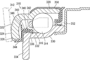
図5に本発明の実施例4におけるクラッチレリーズ軸受310の部分断面図を示す。クラッチレリーズ軸受310は外輪320と、内輪330と、外輪320と内輪330の間に転動可能に配置された複数の玉(転動体)314と、保持器316とを備えた外輪回転タイプのクラッチレリーズ軸受である。
そして、外輪320の一端部には径方向内方に延びる外輪鍔部322が形成されると共に、外輪鍔部322の軸受外方の側面はダイヤフラムスプリング312が接触する接触面324とされている。そして、外輪鍔部322が形成された一側と同じ側の内輪330の一側端部には、径方向内方に延びる内輪鍔部334が外輪鍔部322と所定の間隔をおいて形成されている。そして、内輪330には、内輪鍔部334から軸受内方に、軸線方向に円筒形の筒状部332が形成されている。
なお、外輪320および内輪330はプレス加工により形成される。
そして、外輪320の一端部には径方向内方に延びる外輪鍔部322が形成されると共に、外輪鍔部322の軸受外方の側面はダイヤフラムスプリング312が接触する接触面324とされている。そして、外輪鍔部322が形成された一側と同じ側の内輪330の一側端部には、径方向内方に延びる内輪鍔部334が外輪鍔部322と所定の間隔をおいて形成されている。そして、内輪330には、内輪鍔部334から軸受内方に、軸線方向に円筒形の筒状部332が形成されている。
なお、外輪320および内輪330はプレス加工により形成される。
そして、内輪330の筒状部332から内輪鍔部334に跨って、第1シール部材340が配設されている。この第1シール部材340が本発明のシール部材に相当する。この第1シール部材340は、金属製の芯金342にゴム製の被覆部343を装着した円環状の部材であって、内輪330に対して内輪鍔部334が形成された側から圧入され、内輪330の筒状部332に形成された係合溝336に係合して内輪330に固定されている。そして、第1シール部材340は、被覆部343と一体で形成されたゴム製のアキシアルリップ344と、被覆部343と一体で形成されたゴム製のシールリップ346を備えている。
そして、アキシアルリップ344は、外輪鍔部322の先端326と狭小な間隔で近接し外輪320と非接触となる構成とされ、シールリップ346は、外輪鍔部322の軸受内方の側面と狭小な間隔で近接し外輪鍔部322と非接触となる構成とされている。
なお、実施例4では被覆部343、アキシアルリップ344及びシールリップ346をゴム製としているが、これらは、軟質樹脂製としても良い。
そして、アキシアルリップ344は、外輪鍔部322の先端326と狭小な間隔で近接し外輪320と非接触となる構成とされ、シールリップ346は、外輪鍔部322の軸受内方の側面と狭小な間隔で近接し外輪鍔部322と非接触となる構成とされている。
なお、実施例4では被覆部343、アキシアルリップ344及びシールリップ346をゴム製としているが、これらは、軟質樹脂製としても良い。
そして、クラッチレリーズ軸受310の他端部には、外輪320に外嵌めされた第2シール部材350が装着されており、第2シール部材350の先端に形成されたシールリップ352が内輪330の外周面に摺接する構成とされている。
この実施例4のクラッチレリーズ軸受310によれば、外輪鍔部322の先端326と第1シール部材340のアキシアルリップ344との間でラビリンスを形成するため、泥水などの異物のクラッチレリーズ軸受310の内部への侵入を抑止することが出来る。また、外輪鍔部322の軸受内方の側面と第1シール部材340のシールリップ346がラビリンスを形成するため、グリース等の潤滑油の軸受内部からの流出を抑止することが出来る。そして、第1シール部材340のアキシアルリップ344及びシールリップ346はいずれも外輪鍔部322と非接触であるため、接触タイプのシール部材を用いる場合と比べて、トルクの損失を低減させることが出来る。また、外輪鍔部322の軸受内側に設けられるシールリップ346を非接触タイプとすることで、接触タイプのように摩耗等による変形に備えてシールリップを厚く設定する必要が無く、シールリップ346を薄くできるので、接触タイプに比べてシールリップ346の容積が減り、グリース等の潤滑油を封入する容積を増加させることができる。
よって、良好な潤滑性と耐水性を維持することができ、かつ、トルク損失を低減させたクラッチレリーズ軸受を提供することすることができる。
よって、良好な潤滑性と耐水性を維持することができ、かつ、トルク損失を低減させたクラッチレリーズ軸受を提供することすることができる。
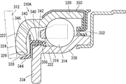
図6に本発明の実施例5におけるクラッチレリーズ軸受310Aの部分断面図を示す。クラッチレリーズ軸受310Aは、外輪鍔部322の先端326の軸受外方に、軸受内方から軸受外方に向かって径方向内方から径方向外方へ傾斜する面取りがなされた面取り部328が形成されていることに特徴がある。実施例5のクラッチレリーズ軸受310Aの他の構成は実施例4のクラッチレリーズ軸受310と同様であるので、同じ符号を付して、詳細な説明は省略する。
実施例5では、外輪鍔部322の軸受外方の先端326に面取り部328を設けることにより、外輪鍔部322の先端326の面取り部328の近くに介在する泥水等の異物が、外輪320の回転による遠心力により軸受の径方向外方かつ軸受外方に誘導されるため、クラッチレリーズ軸受310Aの防水性能が更に向上する。
実施例5では、外輪鍔部322の軸受外方の先端326に面取り部328を設けることにより、外輪鍔部322の先端326の面取り部328の近くに介在する泥水等の異物が、外輪320の回転による遠心力により軸受の径方向外方かつ軸受外方に誘導されるため、クラッチレリーズ軸受310Aの防水性能が更に向上する。
図7に本発明の実施例6におけるクラッチレリーズ軸受310Bの部分断面図を示す。クラッチレリーズ軸受310Bは、外輪鍔部322の先端326の軸受外方に、実施例5と同様の面取りがなされて面取り部328が形成され、更に外輪鍔部322の先端326の軸受内方にも面取りがなされて面取り部329が形成されている。そして、外輪鍔部322の先端326の、第1シール部材340のアキシアルリップ344に対して非接触の近接状態となる範囲が、軸線方向で狭小な幅とされていることを特徴とする。
実施例6のクラッチレリーズ軸受310Bは、外輪鍔部322の先端326の両側で面取りがされている以外は、実施例4のクラッチレリーズ軸受310と同様の構成であるので、同じ符号を付して、詳細な説明は省略する。
実施例6では、外輪鍔部322の先端326の両側に面取りがなされ、外輪鍔部322の先端326の、第1シール部材340のアキシアルリップ344に対して非接触の近接状態となる範囲が、軸線方向で狭小な幅とされているため、ダイヤフラムスプリング312からのトルク伝達時に外輪鍔部322が変形して外輪鍔部322の先端326がアキシアルリップ344に接触した場合でも、接触する幅が狭小なため、接触摩擦によるトルク損失を低く抑えることができる。
実施例6のクラッチレリーズ軸受310Bは、外輪鍔部322の先端326の両側で面取りがされている以外は、実施例4のクラッチレリーズ軸受310と同様の構成であるので、同じ符号を付して、詳細な説明は省略する。
実施例6では、外輪鍔部322の先端326の両側に面取りがなされ、外輪鍔部322の先端326の、第1シール部材340のアキシアルリップ344に対して非接触の近接状態となる範囲が、軸線方向で狭小な幅とされているため、ダイヤフラムスプリング312からのトルク伝達時に外輪鍔部322が変形して外輪鍔部322の先端326がアキシアルリップ344に接触した場合でも、接触する幅が狭小なため、接触摩擦によるトルク損失を低く抑えることができる。
次に、図8(A)~(D)により本発明の変形実施例について説明する。
図8(A)は、外輪鍔部322の先端326の軸受外方を矩形に切り欠いた切り欠き部327Aを形成して外輪鍔部322の先端326の軸線方向の幅を狭くした構成とし、外輪鍔部322の先端326と向き合うアキシアルリップ344の延びる向きをほぼ軸線に平行とした例である。この構成によっても、ダイヤフラムスプリング312からのトルク伝達時に外輪鍔部322が変形して外輪鍔部322の先端326がアキシアルリップ344に接触した場合のトルク損失を低く抑えることができる。
図8(B)は、外輪鍔部322の先端326の軸受外方に円弧状の弧状部327Bを形成し、外輪鍔部322の軸受内方は面取りをして面取り部329を形成した例である。この構成では、外輪320のプレス加工により弧状部327Bを成形出来るので、面取りをする場合に比べて外輪320の加工が容易となる。
図8(C)は、外輪320の先端326の両側を面取りした上に、アキシアルリップ344の先端を径方向外方へ曲げた構成としたものである。この構成によれば、面取り部328とアキシアルリップ344で形成されるラビリンスが軸受外方に向かって径方向外方に傾斜するため、ラビリンスに介在する泥水等の異物が外輪320の回転による遠心力により軸受外方へ導かれる効果がある。
図8(D)は、曲げ加工により外輪鍔部322の先端326の軸受外方に、軸受内方から軸受外方に向かって径方向内方から径方向外方に傾斜する傾斜部327Dを形成したものである。曲げ加工により傾斜部を形成するので、切削加工による面取りによって傾斜部を形成する方法に比べて外輪320の加工が容易である。
図8(A)は、外輪鍔部322の先端326の軸受外方を矩形に切り欠いた切り欠き部327Aを形成して外輪鍔部322の先端326の軸線方向の幅を狭くした構成とし、外輪鍔部322の先端326と向き合うアキシアルリップ344の延びる向きをほぼ軸線に平行とした例である。この構成によっても、ダイヤフラムスプリング312からのトルク伝達時に外輪鍔部322が変形して外輪鍔部322の先端326がアキシアルリップ344に接触した場合のトルク損失を低く抑えることができる。
図8(B)は、外輪鍔部322の先端326の軸受外方に円弧状の弧状部327Bを形成し、外輪鍔部322の軸受内方は面取りをして面取り部329を形成した例である。この構成では、外輪320のプレス加工により弧状部327Bを成形出来るので、面取りをする場合に比べて外輪320の加工が容易となる。
図8(C)は、外輪320の先端326の両側を面取りした上に、アキシアルリップ344の先端を径方向外方へ曲げた構成としたものである。この構成によれば、面取り部328とアキシアルリップ344で形成されるラビリンスが軸受外方に向かって径方向外方に傾斜するため、ラビリンスに介在する泥水等の異物が外輪320の回転による遠心力により軸受外方へ導かれる効果がある。
図8(D)は、曲げ加工により外輪鍔部322の先端326の軸受外方に、軸受内方から軸受外方に向かって径方向内方から径方向外方に傾斜する傾斜部327Dを形成したものである。曲げ加工により傾斜部を形成するので、切削加工による面取りによって傾斜部を形成する方法に比べて外輪320の加工が容易である。
その他、本発明に係るクラッチレリーズ軸受はその発明の思想の範囲で、各種の形態で実施できるものである。
Claims (9)
- 外輪と、内輪と、外輪と内輪の間に転動可能に配置された複数の転動体と、転動体を回動自在に保持する保持器を備え、
前記外輪の一側端部には径方向内方に延びる外輪鍔部が形成されると共に、該外輪鍔部の軸受外部の側面はクラッチ機構の回転部材が接触する接触面とされ、該外輪鍔部が形成された一側と軸線方向の反対側には、該外輪に固定されたシール部材が配設されており、該シール部材の径方向内方の先端に形成されたシールリップが該内輪の外周面に摺接する構成とされているクラッチレリーズ軸受であって、
前記シール部材の軸受外方には前記内輪と一体的とされた円環状の相手部材が配設されており、該シール部材の軸受外方の側面に軸受外方に向けて延設され相手部材の径方向外方に向けて延びるアキシアルリップが形成されており、該アキシアルリップは該相手部材と非接触の近接状態でラビリンスを形成し、該アキシアルリップの該シール部材への付け根部に径方向外方に開口した溝が形成されていることを特徴とするクラッチレリーズ軸受。 - 請求項1に記載のクラッチレリーズ軸受であって、
前記シール部材のシールリップが前記内輪の外径面に摺接する位置の軸受外方位置で、該内輪の外径面に溝が形成されていることを特徴とするクラッチレリーズ軸受。 - 請求項1または請求項2に記載のクラッチレリーズ軸受であって、
前記シール部材の軸受外方の側面の前記アキシアルリップよりも径方向内方位置で、該シール部材の軸受外方の側面に凹部または凸部が形成されていることを特徴とするクラッチレリーズ軸受。 - 請求項1~請求項3のいずれかの請求項に記載のクラッチレリーズ軸受であって、
前記相手部材と前記シール部材が非接触の近接状態でラビリンスを形成することを特徴とするクラッチレリーズ軸受。 - 請求項1~請求項3のいずれかの請求項に記載のクラッチレリーズ軸受であって、
前記相手部材はクラッチレリーズ軸受の調心を円滑におこなうためのガイドであって、前記シール部材と該ガイドの間に前記内輪に固定され径方向外方に延在するスリンガが配設されており、該シール部材と該スリンガは軸線方向で非接触の近接状態でラビリンスを形成し、該スリンガと該ガイドは軸線方向でラビリンスが形成されない離間状態とされていることを特徴とするクラッチレリーズ軸受。 - 請求項1~請求項3のいずれかの請求項に記載のクラッチレリーズ軸受であって、
前記相手部材は前記内輪から径方向外方に延設された内輪鍔部であって、該内輪鍔部には軸受内方に向かって拡径する突起部が形成されており、該突起部の先端はシール部材の軸受外方の側面に非接触の近接状態とされていることを特徴とするクラッチレリーズ軸受。 - 外輪と、内輪と、外輪と内輪の間に転動可能に配置された複数の転動体とを備え、
前記外輪の一側端部には径方向内方に延びる外輪鍔部が形成されると共に、該外輪鍔部の軸受外部の側面はダイヤフラムスプリングが接触する接触面とされ、該外輪鍔部が形成された一側と同じ側の前記内輪の一側端部には、径方向内方に延びる内輪鍔部が前記外輪鍔部と所定の間隔をおいて形成された、クラッチレリーズ軸受であって、
前記内輪の一側端部から内輪鍔部にかけて、シール部材が配設されており、該シール部材には、前記外輪鍔部の先端と非接触の近接状態として配設されるアキシアルリップと、前記外輪鍔部の軸受内部の側面と非接触の近接状態として配設されるシールリップが形成されていることを特徴とするクラッチレリーズ軸受。 - 請求項7に記載のクラッチレリーズ軸受であって、
前記外輪鍔部の先端の軸受外方に、軸受内方から軸受外方に向かって径方向内方から径方向外方へ傾斜する面取りがなされていることを特徴とするクラッチレリーズ軸受。 - 請求項7又は請求項8に記載のクラッチレリーズ軸受であって、
前記外輪鍔部の先端の、前記シール部材のアキシアルリップに対して非接触の近接状態とされる範囲が、軸線方向で狭小な幅とされていることを特徴とするクラッチレリーズ軸受。
Priority Applications (3)
| Application Number | Priority Date | Filing Date | Title |
|---|---|---|---|
| US12/995,013 US8534926B2 (en) | 2008-05-27 | 2009-05-27 | Clutch release bearing |
| EP09754724.4A EP2287486B1 (en) | 2008-05-27 | 2009-05-27 | Clutch release bearing |
| CN2009801197796A CN102046998B (zh) | 2008-05-27 | 2009-05-27 | 离合器分离轴承 |
Applications Claiming Priority (4)
| Application Number | Priority Date | Filing Date | Title |
|---|---|---|---|
| JP2008-137938 | 2008-05-27 | ||
| JP2008-137939 | 2008-05-27 | ||
| JP2008137938A JP5223459B2 (ja) | 2008-05-27 | 2008-05-27 | クラッチレリーズ軸受 |
| JP2008137939A JP5223460B2 (ja) | 2008-05-27 | 2008-05-27 | クラッチレリーズ軸受 |
Publications (1)
| Publication Number | Publication Date |
|---|---|
| WO2009145216A1 true WO2009145216A1 (ja) | 2009-12-03 |
Family
ID=41377087
Family Applications (1)
| Application Number | Title | Priority Date | Filing Date |
|---|---|---|---|
| PCT/JP2009/059667 Ceased WO2009145216A1 (ja) | 2008-05-27 | 2009-05-27 | クラッチレリーズ軸受 |
Country Status (4)
| Country | Link |
|---|---|
| US (1) | US8534926B2 (ja) |
| EP (1) | EP2287486B1 (ja) |
| CN (1) | CN102046998B (ja) |
| WO (1) | WO2009145216A1 (ja) |
Cited By (7)
| Publication number | Priority date | Publication date | Assignee | Title |
|---|---|---|---|---|
| JP2009180309A (ja) * | 2008-01-31 | 2009-08-13 | Jtekt Corp | クラッチレリーズ軸受 |
| FR2955367A1 (fr) * | 2010-01-20 | 2011-07-22 | Snr Roulements Sa | Butee d'embrayage de vehicule automobile equipee d'un dispositif d'etancheite |
| US20110253500A1 (en) * | 2007-02-20 | 2011-10-20 | Eaton Corporation | Release bearing assembly |
| US20120189237A1 (en) * | 2010-09-20 | 2012-07-26 | Aktiebolaget Skf | Suspension thrust bearing device |
| EP2405153A3 (en) * | 2010-07-05 | 2013-11-13 | Jtekt Corporation | Clutch release bearing device |
| DE102016204500B3 (de) * | 2016-03-18 | 2017-08-03 | Schaeffler Technologies AG & Co. KG | Ausrücklager |
| US10006503B2 (en) * | 2013-12-16 | 2018-06-26 | Nsk Ltd. | Release bearing and clutch release bearing device |
Families Citing this family (15)
| Publication number | Priority date | Publication date | Assignee | Title |
|---|---|---|---|---|
| DE102011003826A1 (de) * | 2011-02-09 | 2012-08-09 | Zf Friedrichshafen Ag | Kupplung |
| FR2972037B1 (fr) * | 2011-02-25 | 2015-06-26 | Ntn Snr Roulements | Butee d'embrayage de vehicule automobile |
| JP5800148B2 (ja) * | 2011-12-21 | 2015-10-28 | Nok株式会社 | エンジンリアシール |
| US20150377299A1 (en) * | 2012-10-19 | 2015-12-31 | Aktiebolaget Skf | Rolling bearing with sealing subassembly |
| CN103470618B (zh) * | 2013-09-01 | 2015-11-18 | 南通儒尚电动车科技有限公司 | 车用离合器轴承 |
| FR3013245B1 (fr) * | 2013-11-19 | 2016-01-15 | Skf Ab | Procede de fabrication d'une bague exterieure de roulement et dispositif de butee de debrayage |
| FR3020421B1 (fr) | 2014-04-24 | 2016-12-30 | Skf Ab | Palier a roulement, notamment pour dispositif de butee de debrayage |
| FR3020423B1 (fr) * | 2014-04-25 | 2016-12-30 | Skf Ab | Palier a roulement, notamment pour dispositif de butee de debrayage |
| DE102014111593A1 (de) * | 2014-08-13 | 2016-02-18 | Khalid Abu Snima | Selbstjustierendes Ausrücklager |
| FR3034152B1 (fr) * | 2015-03-24 | 2018-07-20 | Aktiebolaget Skf | Palier comprenant une bague d'usure surmoulee, et procede de fabrication associe |
| CN104895934A (zh) * | 2015-06-05 | 2015-09-09 | 安徽利达汽车轴承制造有限公司 | 一种轴承密封圈 |
| US10226963B2 (en) | 2016-03-24 | 2019-03-12 | Cnh Industrial America Llc | Face seal with installation pilot for a wheel assembly of a work vehicle |
| JP6439758B2 (ja) * | 2016-07-25 | 2018-12-19 | 株式会社ジェイテクト | 密封型スラスト玉軸受 |
| EP3658792A4 (en) * | 2017-07-22 | 2020-12-16 | Texspin Bearings Limited | SELF-ALIGNING CLUTCH RELEASE BEARING |
| FR3078120B1 (fr) * | 2018-02-21 | 2020-04-17 | Ntn-Snr Roulements | Butee d'embrayage de vehicule automobile equipee d'un dispositif d'etancheite du cote arriere du chemin de roulement |
Citations (6)
| Publication number | Priority date | Publication date | Assignee | Title |
|---|---|---|---|---|
| JP2001311437A (ja) | 2000-04-28 | 2001-11-09 | Koyo Seiko Co Ltd | クラッチレリーズ軸受 |
| JP2003314573A (ja) * | 2002-04-23 | 2003-11-06 | Nsk Ltd | 転がり軸受 |
| JP2004176782A (ja) * | 2002-11-26 | 2004-06-24 | Nsk Ltd | シール及びクラッチレリーズ軸受装置 |
| JP2006009826A (ja) | 2004-06-22 | 2006-01-12 | Nsk Ltd | クラッチレリーズ軸受装置 |
| JP2006189086A (ja) | 2005-01-06 | 2006-07-20 | Ntn Corp | クラッチレリーズ軸受 |
| JP2006207619A (ja) * | 2005-01-25 | 2006-08-10 | Nsk Ltd | クラッチレリーズ軸受 |
Family Cites Families (26)
| Publication number | Priority date | Publication date | Assignee | Title |
|---|---|---|---|---|
| DE7608568U1 (ja) * | 1900-01-01 | S.A. Francaise Du Ferodo, Paris | ||
| DE7036423U (de) * | 1970-10-02 | 1971-01-07 | Skf Kugellagerfabriken Gmbh | Kupplungslager. |
| JPS505750A (ja) * | 1972-12-09 | 1975-01-21 | ||
| DE3103319C2 (de) * | 1981-01-31 | 1983-01-13 | Goetze Ag, 5093 Burscheid | "Lippendichtungsring" |
| JPS5930933U (ja) | 1982-08-23 | 1984-02-25 | 株式会社不二越 | 薄肉鋼板製軸受のシ−ル |
| FR2536482A1 (fr) * | 1982-11-24 | 1984-05-25 | Skf Cie Applic Mecanique | Butee d'embrayage a amortissement de bruit et de vibrations |
| JPS63289331A (ja) * | 1987-05-21 | 1988-11-25 | Nachi Fujikoshi Corp | クラッチレリ−ズ軸受装置 |
| US4815867A (en) * | 1987-09-23 | 1989-03-28 | Federal-Mogul Corporation | Side assembled clip for self-aligning bearing |
| JPH02138230U (ja) * | 1989-04-24 | 1990-11-19 | ||
| JPH044325A (ja) | 1990-04-19 | 1992-01-08 | Koyo Seiko Co Ltd | 自動調心形クラッチレリーズ軸受装置 |
| FR2661470B1 (fr) * | 1990-04-27 | 1994-11-25 | Ina Roulements Sa | Roulement de butee, notamment a usage de butee de debrayage. |
| FR2663702B1 (fr) * | 1990-06-21 | 1995-05-12 | Skf France | Butee d'embrayage comportant des moyens de solidarisation avec l'organe de manóoeuvre. |
| US5150778A (en) * | 1991-05-31 | 1992-09-29 | Federal-Mogul Corporation | Self-aligning clutch release bearing assembly |
| DE4412928A1 (de) * | 1994-04-15 | 1995-10-19 | Schaeffler Waelzlager Kg | Hydraulisch betätigbare Vorrichtung zum Ausrücken einer Schalttrennkupplung eines Kraftfahrzeugs |
| GB9623126D0 (en) * | 1996-11-06 | 1997-01-08 | Timken Co | Bearing assembly |
| FR2756602B1 (fr) * | 1996-11-29 | 1999-01-15 | Skf France | Dispositif debrayeur |
| FR2759437B1 (fr) * | 1997-02-13 | 1999-05-07 | Skf France | Dispositif de manoeuvre d'embrayage a organe elastique d'autoalignement |
| DE19716218C2 (de) * | 1997-04-18 | 2001-08-30 | Schaeffler Waelzlager Ohg | Kupplungsausrücklager |
| DE19981436D2 (de) * | 1998-07-24 | 2001-07-12 | Luk Lamellen & Kupplungsbau | Dichtung für ein hydraulisch betätigtes Ausrücksystem |
| FR2798172B1 (fr) * | 1999-09-07 | 2001-11-23 | Skf France | Butee de debrayage a auto-alignement par manchon |
| DE10114845B4 (de) * | 2001-03-24 | 2012-05-31 | Schaeffler Technologies Gmbh & Co. Kg | Selbsteinstellendes Kupplungsausrücklager |
| DE10124663A1 (de) * | 2001-05-18 | 2002-11-21 | Ina Schaeffler Kg | Selbsteinstellendes Kupplungsausrücklager |
| JP4822537B2 (ja) | 2004-07-16 | 2011-11-24 | Nok株式会社 | 密封装置 |
| JP4507734B2 (ja) | 2004-07-22 | 2010-07-21 | 日本精工株式会社 | 車輪支持用転がり軸受ユニット |
| DE102005053612A1 (de) * | 2005-11-10 | 2007-05-16 | Schaeffler Kg | Ausrücklager für eine Betätigungseinrichtung einer Schaltkupplung |
| JP2008232405A (ja) * | 2007-03-23 | 2008-10-02 | Jtekt Corp | クラッチレリーズ軸受 |
-
2009
- 2009-05-27 WO PCT/JP2009/059667 patent/WO2009145216A1/ja not_active Ceased
- 2009-05-27 CN CN2009801197796A patent/CN102046998B/zh not_active Expired - Fee Related
- 2009-05-27 EP EP09754724.4A patent/EP2287486B1/en active Active
- 2009-05-27 US US12/995,013 patent/US8534926B2/en not_active Expired - Fee Related
Patent Citations (6)
| Publication number | Priority date | Publication date | Assignee | Title |
|---|---|---|---|---|
| JP2001311437A (ja) | 2000-04-28 | 2001-11-09 | Koyo Seiko Co Ltd | クラッチレリーズ軸受 |
| JP2003314573A (ja) * | 2002-04-23 | 2003-11-06 | Nsk Ltd | 転がり軸受 |
| JP2004176782A (ja) * | 2002-11-26 | 2004-06-24 | Nsk Ltd | シール及びクラッチレリーズ軸受装置 |
| JP2006009826A (ja) | 2004-06-22 | 2006-01-12 | Nsk Ltd | クラッチレリーズ軸受装置 |
| JP2006189086A (ja) | 2005-01-06 | 2006-07-20 | Ntn Corp | クラッチレリーズ軸受 |
| JP2006207619A (ja) * | 2005-01-25 | 2006-08-10 | Nsk Ltd | クラッチレリーズ軸受 |
Cited By (14)
| Publication number | Priority date | Publication date | Assignee | Title |
|---|---|---|---|---|
| US20110253500A1 (en) * | 2007-02-20 | 2011-10-20 | Eaton Corporation | Release bearing assembly |
| US8672114B2 (en) * | 2007-02-20 | 2014-03-18 | Eaton Corporation | Release bearing assembly |
| JP2009180309A (ja) * | 2008-01-31 | 2009-08-13 | Jtekt Corp | クラッチレリーズ軸受 |
| CN102792044B (zh) * | 2010-01-20 | 2015-05-13 | Ntn-Snr轴承股份有限公司 | 配有密封装置的机动车的离合器分离轴承 |
| CN102792044A (zh) * | 2010-01-20 | 2012-11-21 | Ntn-Snr轴承股份有限公司 | 配有密封装置的机动车的离合器分离轴承 |
| WO2011089335A1 (fr) * | 2010-01-20 | 2011-07-28 | Ntn-Snr Roulements | Butee d'embrayage de vehicule automobile equipee d'un dispositif d'etancheite |
| FR2955367A1 (fr) * | 2010-01-20 | 2011-07-22 | Snr Roulements Sa | Butee d'embrayage de vehicule automobile equipee d'un dispositif d'etancheite |
| RU2559673C2 (ru) * | 2010-01-20 | 2015-08-10 | Нтн-Снр Рульман | Подшипник выключения сцепления автомобиля, снабженный уплотнительным устройством, и система воздействия на сцепление автомобиля |
| EP2405153A3 (en) * | 2010-07-05 | 2013-11-13 | Jtekt Corporation | Clutch release bearing device |
| US20120189237A1 (en) * | 2010-09-20 | 2012-07-26 | Aktiebolaget Skf | Suspension thrust bearing device |
| US8840316B2 (en) * | 2010-09-20 | 2014-09-23 | Aktiebolaget Skf | Suspension thrust bearing device |
| US10006503B2 (en) * | 2013-12-16 | 2018-06-26 | Nsk Ltd. | Release bearing and clutch release bearing device |
| DE102016204500B3 (de) * | 2016-03-18 | 2017-08-03 | Schaeffler Technologies AG & Co. KG | Ausrücklager |
| US10473155B2 (en) | 2016-03-18 | 2019-11-12 | Schaeffler Technologies AG & Co. KG | Release bearing |
Also Published As
| Publication number | Publication date |
|---|---|
| EP2287486A4 (en) | 2017-05-24 |
| CN102046998A (zh) | 2011-05-04 |
| US20110129175A1 (en) | 2011-06-02 |
| CN102046998B (zh) | 2013-07-03 |
| EP2287486A1 (en) | 2011-02-23 |
| US8534926B2 (en) | 2013-09-17 |
| EP2287486B1 (en) | 2019-07-10 |
Similar Documents
| Publication | Publication Date | Title |
|---|---|---|
| US8534926B2 (en) | Clutch release bearing | |
| JP6519483B2 (ja) | レリーズ軸受及びクラッチレリーズ軸受装置 | |
| WO2017204058A1 (ja) | 軸受密封装置 | |
| TWI321624B (en) | Rotary shaft support structure of industrial vehicle | |
| JP2014234851A (ja) | 密封装置付転がり軸受 | |
| JP5223459B2 (ja) | クラッチレリーズ軸受 | |
| JP2008232284A (ja) | 転がり軸受の密封装置 | |
| JP5223460B2 (ja) | クラッチレリーズ軸受 | |
| JP2009287602A (ja) | クラッチレリーズ軸受 | |
| JP2007192258A (ja) | シール付き転がり軸受 | |
| JP2007270873A (ja) | 密封装置 | |
| JP2005325867A (ja) | 鉄道車両用軸受 | |
| WO2009084355A1 (ja) | クラッチレリーズ軸受およびこれを備えるクラッチレリーズ軸受装置 | |
| JP5293420B2 (ja) | 密封装置 | |
| JP2023031532A (ja) | 転がり軸受、および、転がり軸受装置 | |
| JP2008223996A (ja) | 転がり軸受の密封装置 | |
| JP2009287601A (ja) | クラッチレリーズ軸受 | |
| JP2010169138A (ja) | 転がり軸受密封用のシール | |
| JP2006105189A (ja) | 密封装置 | |
| JP2009287600A (ja) | クラッチレリーズ軸受 | |
| JP2004052793A (ja) | 転がり軸受 | |
| JP2011144868A (ja) | クラッチレリーズ軸受 | |
| JP2010127353A (ja) | クラッチレリーズ軸受装置用玉軸受 | |
| KR101852255B1 (ko) | 클러치 릴리즈 베어링 | |
| JPWO2016043274A1 (ja) | 密封装置 |
Legal Events
| Date | Code | Title | Description |
|---|---|---|---|
| WWE | Wipo information: entry into national phase |
Ref document number: 200980119779.6 Country of ref document: CN |
|
| 121 | Ep: the epo has been informed by wipo that ep was designated in this application |
Ref document number: 09754724 Country of ref document: EP Kind code of ref document: A1 |
|
| WWE | Wipo information: entry into national phase |
Ref document number: 2009754724 Country of ref document: EP |
|
| WWE | Wipo information: entry into national phase |
Ref document number: 12995013 Country of ref document: US |
|
| NENP | Non-entry into the national phase |
Ref country code: DE |