WO2009148011A1 - 温水システム - Google Patents
温水システム Download PDFInfo
- Publication number
- WO2009148011A1 WO2009148011A1 PCT/JP2009/059960 JP2009059960W WO2009148011A1 WO 2009148011 A1 WO2009148011 A1 WO 2009148011A1 JP 2009059960 W JP2009059960 W JP 2009059960W WO 2009148011 A1 WO2009148011 A1 WO 2009148011A1
- Authority
- WO
- WIPO (PCT)
- Prior art keywords
- hot water
- evaporator
- storage tank
- heating
- defrost
- Prior art date
- Legal status (The legal status is an assumption and is not a legal conclusion. Google has not performed a legal analysis and makes no representation as to the accuracy of the status listed.)
- Ceased
Links
Images

Classifications
-
- F—MECHANICAL ENGINEERING; LIGHTING; HEATING; WEAPONS; BLASTING
- F25—REFRIGERATION OR COOLING; COMBINED HEATING AND REFRIGERATION SYSTEMS; HEAT PUMP SYSTEMS; MANUFACTURE OR STORAGE OF ICE; LIQUEFACTION SOLIDIFICATION OF GASES
- F25B—REFRIGERATION MACHINES, PLANTS OR SYSTEMS; COMBINED HEATING AND REFRIGERATION SYSTEMS; HEAT PUMP SYSTEMS
- F25B40/00—Subcoolers, desuperheaters or superheaters
-
- F—MECHANICAL ENGINEERING; LIGHTING; HEATING; WEAPONS; BLASTING
- F24—HEATING; RANGES; VENTILATING
- F24D—DOMESTIC- OR SPACE-HEATING SYSTEMS, e.g. CENTRAL HEATING SYSTEMS; DOMESTIC HOT-WATER SUPPLY SYSTEMS; ELEMENTS OR COMPONENTS THEREFOR
- F24D11/00—Central heating systems using heat accumulated in storage masses
- F24D11/02—Central heating systems using heat accumulated in storage masses using heat pumps
- F24D11/0214—Central heating systems using heat accumulated in storage masses using heat pumps water heating system
-
- F—MECHANICAL ENGINEERING; LIGHTING; HEATING; WEAPONS; BLASTING
- F24—HEATING; RANGES; VENTILATING
- F24D—DOMESTIC- OR SPACE-HEATING SYSTEMS, e.g. CENTRAL HEATING SYSTEMS; DOMESTIC HOT-WATER SUPPLY SYSTEMS; ELEMENTS OR COMPONENTS THEREFOR
- F24D17/00—Domestic hot-water supply systems
- F24D17/02—Domestic hot-water supply systems using heat pumps
-
- F—MECHANICAL ENGINEERING; LIGHTING; HEATING; WEAPONS; BLASTING
- F24—HEATING; RANGES; VENTILATING
- F24H—FLUID HEATERS, e.g. WATER OR AIR HEATERS, HAVING HEAT-GENERATING MEANS, e.g. HEAT PUMPS, IN GENERAL
- F24H15/00—Control of fluid heaters
- F24H15/10—Control of fluid heaters characterised by the purpose of the control
- F24H15/136—Defrosting or de-icing; Preventing freezing
-
- F—MECHANICAL ENGINEERING; LIGHTING; HEATING; WEAPONS; BLASTING
- F24—HEATING; RANGES; VENTILATING
- F24H—FLUID HEATERS, e.g. WATER OR AIR HEATERS, HAVING HEAT-GENERATING MEANS, e.g. HEAT PUMPS, IN GENERAL
- F24H15/00—Control of fluid heaters
- F24H15/20—Control of fluid heaters characterised by control inputs
- F24H15/212—Temperature of the water
-
- F—MECHANICAL ENGINEERING; LIGHTING; HEATING; WEAPONS; BLASTING
- F24—HEATING; RANGES; VENTILATING
- F24H—FLUID HEATERS, e.g. WATER OR AIR HEATERS, HAVING HEAT-GENERATING MEANS, e.g. HEAT PUMPS, IN GENERAL
- F24H15/00—Control of fluid heaters
- F24H15/30—Control of fluid heaters characterised by control outputs; characterised by the components to be controlled
- F24H15/305—Control of valves
- F24H15/32—Control of valves of switching valves
-
- F—MECHANICAL ENGINEERING; LIGHTING; HEATING; WEAPONS; BLASTING
- F25—REFRIGERATION OR COOLING; COMBINED HEATING AND REFRIGERATION SYSTEMS; HEAT PUMP SYSTEMS; MANUFACTURE OR STORAGE OF ICE; LIQUEFACTION SOLIDIFICATION OF GASES
- F25B—REFRIGERATION MACHINES, PLANTS OR SYSTEMS; COMBINED HEATING AND REFRIGERATION SYSTEMS; HEAT PUMP SYSTEMS
- F25B30/00—Heat pumps
- F25B30/02—Heat pumps of the compression type
-
- F—MECHANICAL ENGINEERING; LIGHTING; HEATING; WEAPONS; BLASTING
- F25—REFRIGERATION OR COOLING; COMBINED HEATING AND REFRIGERATION SYSTEMS; HEAT PUMP SYSTEMS; MANUFACTURE OR STORAGE OF ICE; LIQUEFACTION SOLIDIFICATION OF GASES
- F25D—REFRIGERATORS; COLD ROOMS; ICE-BOXES; COOLING OR FREEZING APPARATUS NOT OTHERWISE PROVIDED FOR
- F25D21/00—Defrosting; Preventing frosting; Removing condensed or defrost water
- F25D21/06—Removing frost
- F25D21/12—Removing frost by hot-fluid circulating system separate from the refrigerant system
-
- F—MECHANICAL ENGINEERING; LIGHTING; HEATING; WEAPONS; BLASTING
- F24—HEATING; RANGES; VENTILATING
- F24D—DOMESTIC- OR SPACE-HEATING SYSTEMS, e.g. CENTRAL HEATING SYSTEMS; DOMESTIC HOT-WATER SUPPLY SYSTEMS; ELEMENTS OR COMPONENTS THEREFOR
- F24D2200/00—Heat sources or energy sources
- F24D2200/12—Heat pump
-
- F—MECHANICAL ENGINEERING; LIGHTING; HEATING; WEAPONS; BLASTING
- F24—HEATING; RANGES; VENTILATING
- F24D—DOMESTIC- OR SPACE-HEATING SYSTEMS, e.g. CENTRAL HEATING SYSTEMS; DOMESTIC HOT-WATER SUPPLY SYSTEMS; ELEMENTS OR COMPONENTS THEREFOR
- F24D2220/00—Components of central heating installations excluding heat sources
- F24D2220/04—Sensors
- F24D2220/042—Temperature sensors
-
- F—MECHANICAL ENGINEERING; LIGHTING; HEATING; WEAPONS; BLASTING
- F24—HEATING; RANGES; VENTILATING
- F24D—DOMESTIC- OR SPACE-HEATING SYSTEMS, e.g. CENTRAL HEATING SYSTEMS; DOMESTIC HOT-WATER SUPPLY SYSTEMS; ELEMENTS OR COMPONENTS THEREFOR
- F24D2220/00—Components of central heating installations excluding heat sources
- F24D2220/06—Heat exchangers
-
- F—MECHANICAL ENGINEERING; LIGHTING; HEATING; WEAPONS; BLASTING
- F24—HEATING; RANGES; VENTILATING
- F24D—DOMESTIC- OR SPACE-HEATING SYSTEMS, e.g. CENTRAL HEATING SYSTEMS; DOMESTIC HOT-WATER SUPPLY SYSTEMS; ELEMENTS OR COMPONENTS THEREFOR
- F24D2220/00—Components of central heating installations excluding heat sources
- F24D2220/08—Storage tanks
-
- F—MECHANICAL ENGINEERING; LIGHTING; HEATING; WEAPONS; BLASTING
- F24—HEATING; RANGES; VENTILATING
- F24D—DOMESTIC- OR SPACE-HEATING SYSTEMS, e.g. CENTRAL HEATING SYSTEMS; DOMESTIC HOT-WATER SUPPLY SYSTEMS; ELEMENTS OR COMPONENTS THEREFOR
- F24D2220/00—Components of central heating installations excluding heat sources
- F24D2220/20—Heat consumers
- F24D2220/2009—Radiators
-
- F—MECHANICAL ENGINEERING; LIGHTING; HEATING; WEAPONS; BLASTING
- F24—HEATING; RANGES; VENTILATING
- F24D—DOMESTIC- OR SPACE-HEATING SYSTEMS, e.g. CENTRAL HEATING SYSTEMS; DOMESTIC HOT-WATER SUPPLY SYSTEMS; ELEMENTS OR COMPONENTS THEREFOR
- F24D2220/00—Components of central heating installations excluding heat sources
- F24D2220/20—Heat consumers
- F24D2220/209—Sanitary water taps
-
- F—MECHANICAL ENGINEERING; LIGHTING; HEATING; WEAPONS; BLASTING
- F24—HEATING; RANGES; VENTILATING
- F24D—DOMESTIC- OR SPACE-HEATING SYSTEMS, e.g. CENTRAL HEATING SYSTEMS; DOMESTIC HOT-WATER SUPPLY SYSTEMS; ELEMENTS OR COMPONENTS THEREFOR
- F24D2240/00—Characterizing positions, e.g. of sensors, inlets, outlets
- F24D2240/10—Placed within or inside of
-
- F—MECHANICAL ENGINEERING; LIGHTING; HEATING; WEAPONS; BLASTING
- F24—HEATING; RANGES; VENTILATING
- F24D—DOMESTIC- OR SPACE-HEATING SYSTEMS, e.g. CENTRAL HEATING SYSTEMS; DOMESTIC HOT-WATER SUPPLY SYSTEMS; ELEMENTS OR COMPONENTS THEREFOR
- F24D2240/00—Characterizing positions, e.g. of sensors, inlets, outlets
- F24D2240/12—Placed outside of
-
- F—MECHANICAL ENGINEERING; LIGHTING; HEATING; WEAPONS; BLASTING
- F24—HEATING; RANGES; VENTILATING
- F24D—DOMESTIC- OR SPACE-HEATING SYSTEMS, e.g. CENTRAL HEATING SYSTEMS; DOMESTIC HOT-WATER SUPPLY SYSTEMS; ELEMENTS OR COMPONENTS THEREFOR
- F24D2240/00—Characterizing positions, e.g. of sensors, inlets, outlets
- F24D2240/26—Vertically distributed at fixed positions, e.g. multiple sensors distributed over the height of a tank, or a vertical inlet distribution pipe having a plurality of orifices
-
- F—MECHANICAL ENGINEERING; LIGHTING; HEATING; WEAPONS; BLASTING
- F24—HEATING; RANGES; VENTILATING
- F24H—FLUID HEATERS, e.g. WATER OR AIR HEATERS, HAVING HEAT-GENERATING MEANS, e.g. HEAT PUMPS, IN GENERAL
- F24H15/00—Control of fluid heaters
- F24H15/20—Control of fluid heaters characterised by control inputs
- F24H15/212—Temperature of the water
- F24H15/215—Temperature of the water before heating
-
- F—MECHANICAL ENGINEERING; LIGHTING; HEATING; WEAPONS; BLASTING
- F24—HEATING; RANGES; VENTILATING
- F24H—FLUID HEATERS, e.g. WATER OR AIR HEATERS, HAVING HEAT-GENERATING MEANS, e.g. HEAT PUMPS, IN GENERAL
- F24H15/00—Control of fluid heaters
- F24H15/20—Control of fluid heaters characterised by control inputs
- F24H15/212—Temperature of the water
- F24H15/219—Temperature of the water after heating
-
- F—MECHANICAL ENGINEERING; LIGHTING; HEATING; WEAPONS; BLASTING
- F24—HEATING; RANGES; VENTILATING
- F24H—FLUID HEATERS, e.g. WATER OR AIR HEATERS, HAVING HEAT-GENERATING MEANS, e.g. HEAT PUMPS, IN GENERAL
- F24H15/00—Control of fluid heaters
- F24H15/20—Control of fluid heaters characterised by control inputs
- F24H15/212—Temperature of the water
- F24H15/223—Temperature of the water in the water storage tank
- F24H15/225—Temperature of the water in the water storage tank at different heights of the tank
-
- F—MECHANICAL ENGINEERING; LIGHTING; HEATING; WEAPONS; BLASTING
- F24—HEATING; RANGES; VENTILATING
- F24H—FLUID HEATERS, e.g. WATER OR AIR HEATERS, HAVING HEAT-GENERATING MEANS, e.g. HEAT PUMPS, IN GENERAL
- F24H15/00—Control of fluid heaters
- F24H15/20—Control of fluid heaters characterised by control inputs
- F24H15/254—Room temperature
-
- F—MECHANICAL ENGINEERING; LIGHTING; HEATING; WEAPONS; BLASTING
- F24—HEATING; RANGES; VENTILATING
- F24H—FLUID HEATERS, e.g. WATER OR AIR HEATERS, HAVING HEAT-GENERATING MEANS, e.g. HEAT PUMPS, IN GENERAL
- F24H15/00—Control of fluid heaters
- F24H15/20—Control of fluid heaters characterised by control inputs
- F24H15/258—Outdoor temperature
-
- F—MECHANICAL ENGINEERING; LIGHTING; HEATING; WEAPONS; BLASTING
- F24—HEATING; RANGES; VENTILATING
- F24H—FLUID HEATERS, e.g. WATER OR AIR HEATERS, HAVING HEAT-GENERATING MEANS, e.g. HEAT PUMPS, IN GENERAL
- F24H15/00—Control of fluid heaters
- F24H15/30—Control of fluid heaters characterised by control outputs; characterised by the components to be controlled
- F24H15/305—Control of valves
- F24H15/315—Control of valves of mixing valves
-
- F—MECHANICAL ENGINEERING; LIGHTING; HEATING; WEAPONS; BLASTING
- F24—HEATING; RANGES; VENTILATING
- F24H—FLUID HEATERS, e.g. WATER OR AIR HEATERS, HAVING HEAT-GENERATING MEANS, e.g. HEAT PUMPS, IN GENERAL
- F24H15/00—Control of fluid heaters
- F24H15/30—Control of fluid heaters characterised by control outputs; characterised by the components to be controlled
- F24H15/335—Control of pumps, e.g. on-off control
-
- F—MECHANICAL ENGINEERING; LIGHTING; HEATING; WEAPONS; BLASTING
- F24—HEATING; RANGES; VENTILATING
- F24H—FLUID HEATERS, e.g. WATER OR AIR HEATERS, HAVING HEAT-GENERATING MEANS, e.g. HEAT PUMPS, IN GENERAL
- F24H15/00—Control of fluid heaters
- F24H15/30—Control of fluid heaters characterised by control outputs; characterised by the components to be controlled
- F24H15/355—Control of heat-generating means in heaters
- F24H15/37—Control of heat-generating means in heaters of electric heaters
-
- F—MECHANICAL ENGINEERING; LIGHTING; HEATING; WEAPONS; BLASTING
- F24—HEATING; RANGES; VENTILATING
- F24H—FLUID HEATERS, e.g. WATER OR AIR HEATERS, HAVING HEAT-GENERATING MEANS, e.g. HEAT PUMPS, IN GENERAL
- F24H15/00—Control of fluid heaters
- F24H15/30—Control of fluid heaters characterised by control outputs; characterised by the components to be controlled
- F24H15/375—Control of heat pumps
- F24H15/38—Control of compressors of heat pumps
-
- F—MECHANICAL ENGINEERING; LIGHTING; HEATING; WEAPONS; BLASTING
- F24—HEATING; RANGES; VENTILATING
- F24H—FLUID HEATERS, e.g. WATER OR AIR HEATERS, HAVING HEAT-GENERATING MEANS, e.g. HEAT PUMPS, IN GENERAL
- F24H15/00—Control of fluid heaters
- F24H15/30—Control of fluid heaters characterised by control outputs; characterised by the components to be controlled
- F24H15/375—Control of heat pumps
- F24H15/385—Control of expansion valves of heat pumps
-
- F—MECHANICAL ENGINEERING; LIGHTING; HEATING; WEAPONS; BLASTING
- F25—REFRIGERATION OR COOLING; COMBINED HEATING AND REFRIGERATION SYSTEMS; HEAT PUMP SYSTEMS; MANUFACTURE OR STORAGE OF ICE; LIQUEFACTION SOLIDIFICATION OF GASES
- F25B—REFRIGERATION MACHINES, PLANTS OR SYSTEMS; COMBINED HEATING AND REFRIGERATION SYSTEMS; HEAT PUMP SYSTEMS
- F25B2309/00—Gas cycle refrigeration machines
- F25B2309/06—Compression machines, plants or systems characterised by the refrigerant being carbon dioxide
-
- F—MECHANICAL ENGINEERING; LIGHTING; HEATING; WEAPONS; BLASTING
- F25—REFRIGERATION OR COOLING; COMBINED HEATING AND REFRIGERATION SYSTEMS; HEAT PUMP SYSTEMS; MANUFACTURE OR STORAGE OF ICE; LIQUEFACTION SOLIDIFICATION OF GASES
- F25B—REFRIGERATION MACHINES, PLANTS OR SYSTEMS; COMBINED HEATING AND REFRIGERATION SYSTEMS; HEAT PUMP SYSTEMS
- F25B2339/00—Details of evaporators; Details of condensers
- F25B2339/04—Details of condensers
- F25B2339/047—Water-cooled condensers
Definitions
- the present invention relates to a hot water system such as a hot water supply device or a heating hot water supply device.
- a heating and hot water supply apparatus there is one provided with a heat pump unit disposed outdoors and a hot water storage tank for storing hot water heated by the heat pump unit.
- the above heat pump unit has an evaporator that takes in heat from outside air, but frost may adhere to the evaporator.
- frost adheres to the evaporator
- the heat exchange performance of the evaporator is lowered, and as a result, sufficient heating cannot be performed. For this reason, the defrost driving
- This heating and hot water supply apparatus includes a heat pump unit, a hot water storage tank, and a heating terminal.
- the heat pump unit includes a fan, a first evaporator, a second evaporator, a compressor, a condenser, and an expansion valve.
- the first evaporator is located upstream of the compressor and downstream of the second evaporator.
- the first evaporator receives outside air from the fan and takes in heat from the outside air.
- the heating / hot water supply apparatus configured as described above, while the water in the hot water storage tank is being boiled by the heat pump unit, the hot water in the hot water storage tank is sent to the second evaporator by the pump. Thereby, since the refrigerant
- an object of the present invention is to provide a hot water system that can perform a defrost operation while boiling water in a hot water storage tank and can improve the COP of a heat pump unit even if such a defrost operation is performed. There is to do.
- the hot water system of the present invention is: A heat pump unit having a refrigerant circuit and a first evaporator, a compressor, a condenser and an expansion mechanism provided in the refrigerant circuit; A hot water storage tank for storing hot water, After heating the water in the hot water storage tank through the condenser, a heating circulation circuit for returning and circulating again in the hot water storage tank; A second evaporator provided in the refrigerant circuit; A defrost circulation circuit for circulating the hot water stored in the hot water storage tank through the second evaporator and then returning the hot water to the hot water storage tank; It is provided with the distribution
- the hot water in the hot water storage tank is caused to flow to the defrost circulation circuit under the control of the flow control unit.
- the hot water returns to the hot water storage tank again after passing through the second evaporator.
- the refrigerant that has entered the second evaporator is heated by the hot water and then flows toward the first evaporator.
- the temperature of the refrigerant entering the first evaporator rises, and the frost attached to the first evaporator can be melted.
- the hot water in the hot water storage tank can flow to the circulation circuit for defrost, so defrost operation is performed while boiling the hot water in the hot water storage tank. be able to.
- the defrost operation when the defrost operation is performed by supplying the hot water in the hot water storage tank to the second evaporator, the hot water returns to the hot water storage tank after the temperature is lowered by the second evaporator.
- the low temperature warm water obtained by the defrost operation can be supplied to the heat pump unit.
- the COP of the heat pump unit is improved in the boiling operation after the defrost operation, the COP of the heat pump unit can be improved in the total operation.
- the hot water system of one embodiment is A hot water supply heat exchanger that is disposed in the hot water storage tank and in which hot water flows inside;
- a heating circulation circuit is provided for circulating the hot water stored in the hot water storage tank through the heating terminal outside the hot water storage tank and then returning it to the hot water storage tank.
- the hot water stored in the hot water storage tank flows to the heating terminal via the heating circulation circuit and returns to the hot water storage tank again.
- the heat of the warm water is released into the room through the heating terminal. That is, the heating terminal directly takes out the heat of the hot water in the hot water storage tank and releases it into the room.
- the heat of the hot water in the hot water storage tank can be efficiently supplied to the heating terminal, sufficient heating can be performed even in an area with a high heating load such as Northern Europe.
- the second evaporator is disposed on the downstream side of the first evaporator and on the upstream side of the compressor.
- the second evaporator is disposed on the downstream side of the first evaporator and on the upstream side of the compressor, so that the temperature rises in the first evaporator.
- the refrigerant thus exchanged heat with the hot water supplied from the hot water storage tank to the second evaporator.
- the hot water system of one embodiment is A subcooling heat exchanger disposed on the downstream side of the first evaporator and on the upstream side of the second evaporator;
- the supercooling heat exchanger is arranged on the downstream side of the first evaporator and the upstream side of the second evaporator.
- the temperature of the refrigerant whose temperature has risen further rises in the supercooling heat exchanger.
- the refrigerant whose temperature has further increased in the supercooling heat exchanger enters the second evaporator and exchanges heat with the hot water supplied from the hot water storage tank to the second evaporator.
- the hot water is supplied from the hot water storage tank to the second evaporator as compared with the case where the supercooling heat exchanger is not arranged on the downstream side of the first evaporator and the upstream side of the second evaporator. Hot water is hard to freeze.
- the second evaporator also serves as a supercooling heat exchanger.
- the second evaporator also serves as a supercooling heat exchanger, it is not necessary to provide a supercooling heat exchanger separately from the second evaporator, and the heat pump unit can be reduced in size.
- the second evaporator is A container through which the refrigerant flowing through the refrigerant circuit passes; A heat exchange pipe which is disposed in the container and in which hot water from the hot water storage tank flows.
- the heat exchange pipe since the heat exchange pipe is disposed in the container, the refrigerant that has entered the container contacts the entire surface of the heat exchange pipe.
- the heat of the hot water from the hot water storage tank is efficiently transmitted to the refrigerant in the container through the heat exchange pipe.
- the refrigerant flowing through the refrigerant circuit is a CO 2 refrigerant.
- the heat pump unit can discharge hot water.
- a part of the upstream side of the condenser in the heating circuit is also used as a part of the upstream side of the second evaporator in the defrost circuit
- the flow control unit is provided at a branch portion between the heating circulation circuit and the defrost circulation circuit, and a flow rate of hot water flowing from the upstream side of the condenser in the heating circulation circuit to the condenser; The flow rate of the hot water flowing from the part on the upstream side of the condenser in the heating circuit to the second evaporator is adjusted.
- a part of the upstream side of the condenser in the heating circulation circuit is also used as a part of the upstream side of the second evaporator in the defrosting circulation circuit. If a part of the upstream side of the condenser is constructed, it is not necessary to construct a part of the upstream side of the second evaporator in the defrost circuit.
- the distribution control unit is provided at the branch portion between the heating circulation circuit and the defrost circulation circuit, the distribution of the hot water in the heating circulation circuit and the circulation of the hot water in the defrost circulation circuit are combined into one distribution control unit. Can be controlled.
- the flow control unit allows the minimum amount of warm water to flow through the second evaporator, thereby preventing the warm water in the defrost circulation circuit from being cooled and frozen.
- the hot water system of one embodiment is The amount of hot water flowing into the second evaporator during the defrost operation of the first evaporator is greater than the amount of hot water flowing into the second evaporator during the non-defrost operation of the first evaporator.
- the control part which controls the said distribution control part is provided.
- the control unit controls the flow control unit so that the amount of hot water flowing into the second evaporator during the defrost operation of the first evaporator
- the temperature of the refrigerant entering the second evaporator is reliably increased to a temperature that can be achieved by the defrost of the first evaporator. Can do.
- the hot water system of one embodiment is A temperature detector for detecting the temperature of the hot water discharged from the second evaporator, The control unit controls the distribution control unit based on the output of the temperature detection unit.
- the temperature detection unit detects the temperature of the hot water that leaves the second evaporator and goes to the hot water storage tank. At this time, based on the output of the temperature detection unit, the control unit controls the flow control unit so that the temperature of the hot water that exits the second evaporator and goes to the hot water storage tank does not become, for example, 0 ° C. or less. It is possible to reliably prevent the hot water in the circulation circuit from cooling and freezing.
- the hot water in the hot water storage tank flows through the defrost circulation circuit under the control of the flow control unit. Since the refrigerant enters the second evaporator, the refrigerant entering the second evaporator is heated by the hot water and the temperature rises.
- the refrigerant entering the second evaporator exits the second evaporator, then flows through the refrigerant circuit and returns to the first evaporator, so that the frost attached to the first evaporator is melted. Can do.
- the hot water in the hot water storage tank can flow to the circulation circuit for defrost, so defrost operation is performed while boiling the hot water in the hot water storage tank. be able to.
- the hot water in the hot water storage tank is boiled after the operation is finished, the low temperature hot water obtained by the defrost operation can be supplied to the heat pump unit.
- the COP of the heat pump unit is improved in the boiling operation after the defrost operation, the COP of the heat pump unit can be improved in the total operation.
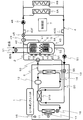
- FIG. 1 is a schematic diagram of a heating and hot water supply apparatus according to a first embodiment of the present invention.
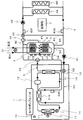
- FIG. 2 is a schematic diagram of a heating and hot water supply apparatus according to a second embodiment of the present invention.
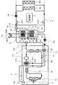
- FIG. 3 is a schematic diagram of a heating and hot water supply apparatus according to a third embodiment of the present invention.
- FIG. 4 is a schematic diagram of a heating and hot water supply apparatus according to a fourth embodiment of the present invention.
- Drawing 1 is a mimetic diagram showing composition of a heating hot-water supply device of a 1st embodiment of the present invention.
- the heating and hot water supply apparatus includes a heat pump unit 1, a hot water storage tank 2, a hot water supply heat exchanger 3, a heating circulation circuit 4, a heating circulation circuit 5 as an example of a heating circulation circuit, and a defrost circulation circuit. 50.
- the heat pump unit 1 includes a refrigerant circuit 16 and an electric blower 17 and boiles water in the hot water storage tank 2 to make warm water.
- the heat pump unit 1 is connected to a hot water storage tank 2 via a boiling circulation circuit 5.
- the refrigerant circuit 16 includes an evaporator 11, a compressor 12, a condenser 13, a supercooling heat exchanger 14, an expansion valve 15, and a defrost heat exchanger 19.
- CO 2 refrigerant circulates.
- the evaporator 11 is an example of a first evaporator
- the expansion valve 15 is an example of an expansion mechanism
- the defrost heat exchanger 19 is an example of a second evaporator.
- the supercooling heat exchanger 14 is disposed downstream of the evaporator 11 and upstream of the defrost heat exchanger 19. Thereby, the temperature of the CO 2 refrigerant traveling from the condenser 13 toward the expansion valve 15 can be lowered.
- the defrost heat exchanger 19 is disposed on the downstream side of the supercooling heat exchanger 14 and on the upstream side of the compressor 12.
- the defrost heat exchanger 19 is connected to the hot water storage tank 2 via a defrost circulation circuit 50.
- the hot water in the hot water storage tank 2 can be supplied to the defrost heat exchanger 19 to increase the temperature of the CO 2 refrigerant from the supercooling heat exchanger 14 toward the compressor 12.
- the CO 2 refrigerant absorbs heat in the air sent from the electric blower 17 and rises in temperature.
- the CO 2 refrigerant is compressed by the compressor 12 and further rises in temperature, and then enters the condenser 13 via the defrost heat exchanger 19 and releases heat.
- the CO 2 refrigerant becomes lower in temperature than before entering the condenser 13 and flows toward the supercooling heat exchanger 14.
- the CO 2 refrigerant is further cooled by the supercooling heat exchanger 14 and then returns to the evaporator 11 via the expansion valve 15.
- the hot water in the hot water storage tank 2 is supplied to the defrost heat exchanger 19 via the defrost circulation circuit 50. For this reason, the CO 2 refrigerant entering the defrost heat exchanger 19 exchanges heat with the hot water from the hot water storage tank 2, and the temperature further rises.
- the defrost heat exchanger 19 is not supplied with hot water from the hot water storage tank 2, so the temperature of the CO 2 refrigerant does not rise in the defrost heat exchanger 19.
- a branch valve 55 is provided in the defrost circulation circuit 50.
- the branch valve 55 has an inlet through which hot water from the hot water storage tank 2 flows and two outlets through which hot water flows out. Of these two outlets, one outlet is connected to the condenser 13 and the other outlet is connected to the defrost heat exchanger 19.
- the amount of warm water entering the condenser 13 can be adjusted by adjusting the opening degree of the one outlet. Further, the amount of hot water entering the defrost heat exchanger 19 can be adjusted by adjusting the opening degree of the other outlet.
- the opening degree of each outlet of the branch valve 7 is adjusted by the control unit 7.
- the branch valve 55 is an example of a flow control unit.
- the boiling circulation circuit 5 is provided with a boiling circulation pump 51 and a boiling three-way valve 52.
- the boiling circulation circuit 5 is connected to the second heating forward connection port 42, the heating supply port 53, and the antifreezing water return connection port 54.
- a part of the upstream side of the condenser 13 in the boiling circulation circuit 5 is also used as a part of the upstream side of the defrost heat exchanger 19 in the defrosting circulation circuit 50. That is, the portion where hot water flows between the hot water storage tank 2 and the branch valve 55 is a part of the boiling circuit 5 and a part of the defrost circuit 50.
- a branch valve 55 is provided at a branch portion between the boiling circuit 5 and the defrost circuit 50.
- the supply port 53 is provided in the lower part of the hot water storage tank 2. Thereby, the hot water in the lower region in the hot water storage tank 2 can be supplied to the boiling circulation pump 51 through the supply port 53.
- the boiling circulation pump 51 sucks the hot water in the lower part of the hot water storage tank 2 and discharges it toward the branch valve 55.
- a variable flow rate pump or a fixed flow rate circulation pump can be employed as the boiling circulation pump 51.
- the heat of the CO 2 refrigerant is transferred to the hot water, and the hot water becomes a high temperature (eg, 60 ° C. to 85 ° C.).
- the hot hot water exiting the condenser 13 goes to the boiling three-way valve 52.
- the boiling three-way valve 52 allows hot hot water from the condenser 13 to flow to the upper region in the hot water storage tank 2 through the second heating forward connection port 42 during hot water supply operation and heating operation. Further, when the heat pump unit 1 is started up, the hot water coming out of the condenser 13 of the heat pump unit 1 is not sufficiently high, so the boiling three-way valve 52 prevents the hot water from the condenser 13 from freezing. It flows through the water return connection port 54 to the lower region in the hot water storage tank 2. Thereby, it is possible to prevent the hot water that has not been sufficiently heated by the condenser 13 from returning to the upper region in the hot water storage tank 2 and disturbing the temperature distribution in the hot water storage tank 2.
- the hot water storage tank 2 stores hot water heated by the heat pump unit 1.
- a heater 6 is disposed at a substantially central portion in the vertical direction in the hot water storage tank 2, and the heater 6 directly heats the hot water in the hot water storage tank 2.
- a plurality of temperature sensors 40A, 40B,..., 40E are provided in the hot water storage tank 2 in order to detect the temperature of the hot water in each part in the hot water storage tank 2.
- the plurality of temperature sensors 40 ⁇ / b> A, 40 ⁇ / b> B,..., 40 ⁇ / b> E detect the temperature of hot water in each part in the hot water storage tank 2 and send a signal indicating the temperature to the control unit 7.
- This hot water supply heat exchanger 3 is formed of a coiled pipe and is arranged from the lower region to the upper region in the hot water storage tank 2.
- the hot water is heated by flowing through the hot water heat exchanger 3. More specifically, the hot water enters the hot water storage tank 2 from the lower part of the hot water storage tank 2 and flows upward through the hot water supply heat exchanger 3 arranged in the lower region of the hot water storage tank 2.
- the hot water flows through the hot water heat exchanger 3 disposed in the upper region of the hot water tank 2 upward, and then flows out of the hot water tank 2 from the upper part of the hot water tank 2.
- the hot water mixing valve 31 is opened, and the hot water supplied from the hot water storage tank 2 and the hot water before flowing into the hot water storage tank 2 are separated. Mix together. Thereby, the temperature of the hot water supplied from the hot water storage tank 2 can be lowered.
- the heating circulation circuit 4 passes the hot water stored in the hot water storage tank 2 through the plurality of heating terminals 8A, 8B,... Outside the hot water storage tank 2, and then returns to the hot water storage tank 2 for circulation. belongs to.
- the heating circulation circuit 4 is connected to the first and second heating forward connection ports 41 and 42 and the heating return connection port 43.
- the first heating outgoing connection port 41 is for taking out hot water in the hot water storage tank 2.
- the first heating / outgoing connection port 41 is provided at a substantially central portion in the vertical direction of the hot water storage tank 2, and is positioned near and above the heater 6. Thereby, the warm water immediately after heated with the said heater 6 can be taken out from the 1st heating outgoing connection port 41, and can be sent to several heating terminal 8A, 8B, ....
- the second heating forward connection port 42 is also for taking out hot water in the hot water storage tank 2 in the same manner as the first heating forward connection port 41.
- the second heating / outgoing connection port 42 is provided in the upper part of the hot water storage tank 2. Thereby, the warm water of the upper area
- the second heating / outgoing connection port 42 is also used as a heating return connection port.
- Each of the heating terminals 8A, 8B,... Directly takes out the heat of hot water flowing from the hot water storage tank 2 and releases it into the room. And the said warm water becomes low temperature, leaves heating terminal 8A, 8B, ..., and flows toward the heating return connection port 43.
- the heating return connection port 43 is provided in the lower part of the hot water storage tank 2. Thereby, the hot water which came out of the said heating return connection port 43 can be mixed with the hot water of the lower area
- the heating circulation circuit 4 is provided with a bypass pipe 44, a heating mixing valve 45, temperature sensors 40F and 40G, a heating circulation pump 48, and a heating three-way valve 49.
- the bypass pipe 44 guides a part of the hot water flowing from the heating terminals 8A, 8B,... To the heating return connection port 43 to the heating mixing valve 45.
- the heating mixing valve 45 has an inlet through which hot water from the hot water storage tank 2 flows and an inlet through which hot water from the bypass pipe 44 flows. Although described in detail later, the opening degree of each inlet of the heating mixing valve 45 is adjusted by the control unit 7.
- the control unit 7 receives the output signal of the outside temperature sensor 18 and the output signals of the temperature sensors 40A, 40B, ..., 40G.
- the control unit 7 also receives a signal indicating the room temperature from a room temperature sensor (not shown).
- the output signal of the outside air temperature sensor 18 is a signal indicating the outside air temperature
- the output signals of the temperature sensors 40A and 40B are signals indicating the temperature of the hot water in the upper region in the hot water storage tank 2
- the output signal of the temperature sensor 40C is the hot water storage.
- a signal indicating the temperature of the hot water in the middle region in the vertical direction in the tank 2 and the output signals of the temperature sensors 40D and 40E are signals indicating the temperature of the hot water in the lower region in the hot water storage tank 2.
- the output signal of the temperature sensor 40F is a signal indicating the temperature of the hot water from the hot water storage tank 2 toward the heating terminals 8A, 8B,.
- the said temperature sensor 40G is a signal which shows the temperature of the warm water which goes to the hot water storage tank 2 from heating terminal 8A, 8B, ....
- the heating circulation pump 48 sucks the hot water in the hot water storage tank 2 through the second heating outgoing connection port 42 or the first heating outgoing connection port 41 and discharges it toward the plurality of heating terminals 8A, 8B,.
- the heating three-way valve 49 extracts hot water from the first heating forward connection port 41 when a high temperature region of the hot water in the hot water storage tank 2 is present in the vicinity of the first heating forward connection port 41. Further, the heating three-way valve 49 extracts hot water from the second heating forward connection port 42 when the high temperature region of the hot water in the hot water storage tank 2 does not exist in the vicinity of the first heating forward connection port 41.
- the control unit 7 switches the heating three-way valve 49. That is, the control unit 7 switches the heating three-way valve 49 based on signals from a plurality of temperature sensors for detecting the temperature of hot water in each part in the hot water storage tank 2.
- the control unit 7 turns on the heating circulation pump 48.
- the hot water stored in the hot water storage tank 2 is sent to the plurality of heating terminals 8A, 8B,... And returned to the hot water storage tank 2 again.
- the heat of the warm water is released into the room via the heating terminal 8. That is, each said heating terminal 8A, 8B, ... takes out the heat of the warm water in the hot water storage tank 2 directly, and discharge
- control unit 7 determines that the compressor 12, the expansion valve 15, the boiling circulation pump 51, and the outside air temperature sensor 18, the temperature sensors 40A, 40B,.
- the branch valve 55 is controlled.
- the control unit 7 determines from the output signals of the temperature sensors 40A, 40B,..., 40E that the hot water in the upper region of the hot water tank 2 is low, the heat pump unit 1 causes the hot water tank 2 to be reduced. Boil the warm water inside. More specifically, the compressor 12 and the boiling circulation pump 51 are turned on, and the expansion valve 15 is opened. At this time, the control unit 7 fully opens the outlet of the branch valve 55 on the condenser 13 side, and fully closes the outlet of the branch valve 55 on the defrost heat exchanger 19 side. Thereby, the hot water in the lower region in the hot water storage tank 2 flows to the condenser 13, and the hot water heated to the high temperature by the condenser 13 enters the hot water storage tank 2 through the second heating forward connection port 42. Return.
- the control unit 7 needs to perform a defrost operation for removing the frost of the evaporator 11 from the output of the outside air temperature sensor 18, for example. If it is determined that, defrost operation is started.
- the control unit 7 increases the opening degree of the expansion valve 15 and opens the outlet of the branch valve 55 on the defrost heat exchanger 19 side.
- warm water having a medium temperature for example, 30 ° C. to 50 ° C.
- the medium-temperature hot water that has entered the defrost heat exchanger 19 gives heat to the CO 2 refrigerant that goes to the compressor 12 to become low-temperature hot water.
- This low temperature hot water returns to the hot water storage tank 2 through the freeze prevention water return connection port 54.
- the hot water of the medium temperature is, after passing through the defrost heat exchanger 19, again by returning to the hot water storage tank 2, the temperature of CO 2 refrigerant entering the evaporator 11 is moderately high. As a result, frost can be removed from the evaporator 11.
- the medium temperature warm water goes through the defrost heat exchanger 19 and the temperature is lowered to become low temperature warm water. Return to the lower area in the hot water storage tank 2.
- the hot water in the hot water storage tank 2 is boiled after the defrost operation is completed, the low temperature hot water in the lower region in the hot water storage tank 2 is supplied to the heat pump unit 1.
- the COP of the heat pump unit 1 is improved, and the COP of the heat pump unit 1 can be expected to be improved in the total operation.
- the defrost heat exchanger 19 is disposed downstream of the supercooling heat exchanger 14, the CO 2 refrigerant whose temperature has increased in the evaporator 11 and the supercooling heat exchanger 14 is transferred to the defrost circuit 50. Absorbs heat from the warm water flowing through. That is, the medium temperature warm water is cooled by the CO 2 refrigerant.
- the hot water of the medium temperature is cooled in a CO 2 refrigerant, because the CO 2 refrigerant is not excessively cold, the temperature rises in the evaporator 11 and the subcooling heat exchanger 14, freezing hot water mesophilic Can be prevented.
- the defrost heat exchanger 19 is disposed between the evaporator 11 and the expansion valve 15, an excessively cold CO 2 refrigerant directed from the expansion valve 15 to the evaporator 11 has a medium temperature flowing through the defrost circulation circuit 50. Since the hot water is cooled, there is a possibility that the medium temperature hot water freezes and the defrosting operation cannot be continued.
- the heat pump unit 1 uses a CO 2 refrigerant, high-temperature hot water can be discharged from the condenser 13.
- the boiling circulation circuit 5 since a part of the upstream side of the condenser 13 in the boiling circulation circuit 5 is also used as a part of the upstream side of the defrost heat exchanger 19 in the defrosting circulation circuit 50, the boiling circulation circuit 5 If a part of the upstream side of the condenser 13 is constructed, it is not necessary to construct a part of the upstream side of the defrost heat exchanger 19 in the defrost circuit 50.
- control unit 7 turns on the circulating pump 51 for boiling, opens the outlet of the branch valve 55 on the defrost heat exchanger 19 side, and circulates for the defrost. A small amount of warm water is allowed to flow through the circuit 50. Thereby, it is possible to prevent the hot water remaining in the defrost circulation circuit 50 from being cooled and frozen.
- FIG. 1 is a schematic diagram showing a configuration of a heating and hot water supply apparatus according to a second embodiment of the present invention.
- FIG. 2 the same components as those of the first embodiment shown in FIG. 1 are denoted by the same reference numerals as those of the components in FIG.
- the heating / hot water supply device includes a defrost heat exchanger 219 instead of the supercooling heat exchanger 14 and the defrost heat exchanger 19 of the first embodiment.
- the defrost heat exchanger 219 using a hot water defrost circulation circuit 50, thereby heating the CO 2 refrigerant heading to the compressor 12 from the evaporator 11, the CO 2 refrigerant heading to the expansion valve 15 from the condenser 13 Cooling. That is, the defrost heat exchanger 219 has both functions of the supercooling heat exchanger 14 and the defrost heat exchanger 19 of the first embodiment.
- a part of the refrigerant circuit 16 between the evaporator 11 and the compressor 12 is connected to a part of the refrigerant circuit 16 between the condenser 13 and the expansion valve 15. It is attached.
- a part of the defrost circuit 50 is also brazed to a part of the refrigerant circuit 16 between the condenser 13 and the expansion valve 15.
- the defrost heat exchanger 219 is only disposed between the evaporator 11 and the compressor 12, so that the heat pump unit 1 can be downsized as compared with the first embodiment. .
- Drawing 3 is a mimetic diagram showing the composition of the heating hot-water supply device of a 3rd embodiment of the present invention.
- FIG. 3 the same components as those of the second embodiment shown in FIG. 2 are denoted by the same reference numerals as those of the components in FIG.
- the heating / hot water supply device includes a temperature sensor 40H as an example of a temperature detection unit.
- the temperature sensor 40H is provided in the defrost circulation circuit 50 and is located downstream of the defrost heat exchanger 219.
- the temperature sensor 40H detects the temperature of the low-temperature hot water from the defrost heat exchanger 19 toward the hot water storage tank 2, and outputs a signal indicating this temperature to the control unit 7.
- the control unit 7 goes from the defrost heat exchanger 19 to the hot water storage tank 2 based on a signal from the temperature sensor 40H.
- the opening degree of the outlet on the defrost heat exchanger 219 side of the branch valve 55 is adjusted so that the temperature of the low-temperature hot water does not become, for example, 0 ° C. or less.
- Drawing 4 is a mimetic diagram showing the composition of the heating hot-water supply device of a 4th embodiment of the present invention.
- FIG. 4 the same components as those of the first embodiment shown in FIG. 1 are denoted by the same reference numerals as those of the components in FIG.
- the heating / hot water supply apparatus includes a defrost heat exchanger 419 instead of the defrost heat exchanger 19 of the first embodiment.
- the defrost heat exchanger 419 includes a container 461 and a coiled heat exchange pipe 462 disposed in the container 461.
- the CO 2 refrigerant that has exited the evaporator 11 enters the container 461 after passing through the supercooling heat exchanger 14. Since the heat exchange pipe 462 is arranged in the container 461, the CO 2 refrigerant contacts the entire surface of the heat exchange pipe 462.
- the heat of the medium temperature hot water from the hot water storage tank 2 is efficiently transmitted to the CO 2 refrigerant in the container 461 through the heat exchange pipe 462.
- the heat pump unit 1 uses the CO 2 refrigerant, but may use an NH 3 refrigerant, an R22 refrigerant, or the like.
- the heating terminals 8A, 8B,... And the heating circulation circuit 4 related thereto may be eliminated to provide a hot water supply device. That is, the present invention is not limited to a heating hot water supply apparatus, and can also be applied to a hot water supply apparatus that performs only hot water supply.
Landscapes
- Engineering & Computer Science (AREA)
- Physics & Mathematics (AREA)
- Mechanical Engineering (AREA)
- Thermal Sciences (AREA)
- General Engineering & Computer Science (AREA)
- Chemical & Material Sciences (AREA)
- Combustion & Propulsion (AREA)
- Heat-Pump Type And Storage Water Heaters (AREA)
Abstract
ヒートポンプユニット1は、冷媒回路16およびこの冷媒回路16に設けられた蒸発器11、圧縮機12、凝縮器13、膨張機構15およびデフロスト熱交換器19を有する。デフロスト熱交換器19は、蒸発器11の下流側、かつ、圧縮機12の上流側に設けられている。デフロスト運転時、貯湯タンク2内の温水がデフロスト用循環回路50を流れてデフロスト熱交換器19に入るようになっている。デフロスト用循環回路50には、デフロスト用循環回路50を流れる温水の流通を制御する分岐弁55が設けられている。
Description
本発明は、例えば給湯装置または暖房給湯装置等の温水システムに関する。
従来、暖房給湯装置としては、屋外に配置ヒートポンプユニットと、このヒートポンプユニットで加熱された温水を貯える貯湯タンクを備えたものがある。
上記ヒートポンプユニットは、外気から熱を取り込む蒸発器を有するが、蒸発器に霜が付着する場合がある。上記蒸発器に霜が付着した状態では、蒸発器の熱交換性能が低下し、ひいては、十分な暖房を行えなくなる。このため、上記蒸発器の霜を取るためのデフロスト運転が必須となる。
上記デフロスト運転が行われている最中は、ヒートポンプユニットで貯湯タンク内の水を沸き上げることができないという問題があった。
この問題を解決する暖房給湯装置としては、特開2004-108597号公報(特許文献1)に記載されている。この暖房給湯装置は、ヒートポンプユニット、貯湯タンクおよび暖房端末を備えている。
上記ヒートポンプユニットは、ファン、第1の蒸発器、第2の蒸発器、圧縮機、凝縮器および膨張弁を有する。
上記第1の蒸発器は、圧縮機の上流側、かつ、第2の蒸発器の下流側に位置している。また、上記第1の蒸発器は、ファンから外気が送られ、その外気から熱を取り込む。
上記構成の暖房給湯装置によれば、ヒートポンプユニットで貯湯タンク内の水を沸き上げている最中、貯湯タンク内の温水をポンプで第2の蒸発器に送る。これにより、上記第1の蒸発器に入る直前の冷媒がその温水で加熱されるので、第1の蒸発器に付着した霜を融かすことができる。
しかしながら、上記特許文献1の暖房給湯装置では、第2の蒸発器で加熱された冷媒が第1の凝縮器に入るため、第1の蒸発器の蒸発温度が上昇する。
その結果、上記第1の蒸発器において外気から取り込む熱量が減少し、ヒートポンプユニットのCOP(成績係数)が低下するという問題が生じてしまう。
そこで、本発明の課題は、貯湯タンク内の水を沸き上げながら、デフロスト運転を行うことができて、しかも、そのようなデフロスト運転を行っても、ヒートポンプユニットのCOPを改善できる温水システムを提供することにある。
上記課題を解決するため、本発明の温水システムは、
冷媒回路およびこの冷媒回路に設けられた第1の蒸発器、圧縮機、凝縮器および膨張機構を有するヒートポンプユニットと、
温水を貯える貯湯タンクと、
上記貯湯タンク内の水を上記凝縮器を経由させて加熱した後、再び、上記貯湯タンク内に戻して循環させるための加熱循環回路と、
上記冷媒回路に設けられた第2の蒸発器と、
上記貯湯タンク内に貯められた温水を上記第2の蒸発器を経由させた後、再び、上記貯湯タンク内に戻して循環させるためのデフロスト用循環回路と、
上記デフロスト用循環回路に設けられ、上記デフロスト用循環回路を流れる温水の流通を制御する流通制御部と
を備えたことを特徴としている。
冷媒回路およびこの冷媒回路に設けられた第1の蒸発器、圧縮機、凝縮器および膨張機構を有するヒートポンプユニットと、
温水を貯える貯湯タンクと、
上記貯湯タンク内の水を上記凝縮器を経由させて加熱した後、再び、上記貯湯タンク内に戻して循環させるための加熱循環回路と、
上記冷媒回路に設けられた第2の蒸発器と、
上記貯湯タンク内に貯められた温水を上記第2の蒸発器を経由させた後、再び、上記貯湯タンク内に戻して循環させるためのデフロスト用循環回路と、
上記デフロスト用循環回路に設けられ、上記デフロスト用循環回路を流れる温水の流通を制御する流通制御部と
を備えたことを特徴としている。
上記構成の温水システムによれば、上記第1の蒸発器の霜を取るためのデフロスト運転を行う場合、流通制御部の制御により、貯湯タンク内の温水をデフロスト用循環回路に流す。これにより、上記温水は、第2の蒸発器を経由した後、再び、貯湯タンク内に戻る。このとき、上記第2の蒸発器に入った冷媒が温水によって加熱された後、第1の蒸発器へ向かって流れる。その結果、上記第1の蒸発器に入る冷媒の温度が上がり、第1の蒸発器に付いた霜を融かすことができる。
また、上記ヒートポンプユニットが貯湯タンク内の温水を沸き上げている最中であっても、貯湯タンク内の温水をデフロスト用循環回路に流せるので、貯湯タンク内の温水を沸き上げながらデフロスト運転を行うことができる。
また、上記貯湯タンク内の温水を第2の蒸発器に供給することによって、デフロスト運転を行った場合、その温水は第2の蒸発器で温度が下がった後、貯湯タンクに戻る。これにより、上記デフロスト運転を終了した後、貯湯タンク内の温水の沸き上げを行う際、デフロスト運転で得た低温の温水をヒートポンプユニットに供給することができる。
したがって、上記デフロスト運転後の沸き上げ運転において、ヒートポンプユニットのCOPが向上するので、運転トータルで、ヒートポンプユニットのCOPの改善が見込める。
一実施形態の温水システムは、
上記貯湯タンク内に配置され、給湯水が内部を流れる給湯用熱交換器と、
上記貯湯タンク内に貯められた温水を上記貯湯タンク外の暖房端末を経由させた後、再び、上記貯湯タンク内に戻して循環させるための暖房用循環回路と
を備える。
上記貯湯タンク内に配置され、給湯水が内部を流れる給湯用熱交換器と、
上記貯湯タンク内に貯められた温水を上記貯湯タンク外の暖房端末を経由させた後、再び、上記貯湯タンク内に戻して循環させるための暖房用循環回路と
を備える。
上記実施形態の温水システムによれば、暖房運転を開始すると、貯湯タンクに貯えた温水が暖房用循環回路を介して暖房端末へ流れ、再び、貯湯タンクに戻る。これにより、上記温水の熱は暖房端末を介して室内に放出される。すなわち、上記暖房端末は、貯湯タンク内の温水の熱を直接取り出し、室内に放出する。
したがって、上記貯湯タンク内の温水の熱を暖房端末に効率良く供給できるので、例えば北欧等の暖房負荷の高い地域でも十分な暖房を行うことができる。
従来においては、貯湯タンク内の熱交換器を介して熱を取り出して、暖房端末に供給していたから、効率が悪くて、十分な暖房を行うことができなかった。
一実施形態の温水システムでは、
上記第2の蒸発器は、上記第1の蒸発器の下流側、かつ、上記圧縮機の上流側に配置されている。
上記第2の蒸発器は、上記第1の蒸発器の下流側、かつ、上記圧縮機の上流側に配置されている。
上記実施形態の温水システムによれば、上記第2の蒸発器は、第1の蒸発器の下流側、かつ、圧縮機の上流側に配置されているので、第1の蒸発器で温度が上昇した冷媒が、貯湯タンクから第2の蒸発器に供給された温水と熱交換する。
したがって、上記貯湯タンクから第2の蒸発器に供給された温水が、過度に冷たい冷媒と熱交換して凍るのを防ぐことができる。
一実施形態の温水システムは、
上記第1の蒸発器の下流側、かつ、上記第2の蒸発器の上流側に配置された過冷却熱交換器を備える。
上記第1の蒸発器の下流側、かつ、上記第2の蒸発器の上流側に配置された過冷却熱交換器を備える。
上記実施形態の温水システムによれば、上記第1の蒸発器の下流側、かつ、第2の蒸発器の上流側に、過冷却熱交換器を配置しているので、第1の蒸発器で温度が上昇した冷媒の温度が過冷却熱交換器でさらに上昇する。そして、上記過冷却熱交換器でさらに温度が上昇した冷媒が、第2の蒸発器に入って、貯湯タンクから第2の蒸発器に供給された温水と熱交換する。
したがって、上記第1の蒸発器の下流側、かつ、第2の蒸発器の上流側に、過冷却熱交換器を配置していない場合よりも、貯湯タンクから第2の蒸発器に供給された温水は凍り難い。
一実施形態の温水システムでは、
上記第2の蒸発器は過冷却熱交換器を兼ねる。
上記第2の蒸発器は過冷却熱交換器を兼ねる。
上記実施形態の温水システムによれば、上記第2の蒸発器は過冷却熱交換器を兼ねるので、第2の蒸発器とは別に過冷却熱交換器を設けなくてもよく、ヒートポンプユニットを小型化できる。
一実施形態の温水システムでは、
上記第2の蒸発器は、
上記冷媒回路を流れる冷媒が通過する容器と、
上記容器内に配置され、上記貯湯タンクからの温水が内部を流れる熱交換パイプと
を有する。
上記第2の蒸発器は、
上記冷媒回路を流れる冷媒が通過する容器と、
上記容器内に配置され、上記貯湯タンクからの温水が内部を流れる熱交換パイプと
を有する。
上記実施形態の温水システムによれば、上記熱交換パイプは容器内に配置されるので、容器内に入った冷媒は熱交換パイプの全表面に接触する。
したがって、上記貯湯タンクからの温水の熱は、熱交換パイプを介して容器内の冷媒に効率良く伝わる。
一実施形態の温水システムでは、
上記冷媒回路を流れる冷媒はCO2冷媒である。
上記冷媒回路を流れる冷媒はCO2冷媒である。
上記実施形態の温水システムによれば、上記冷媒回路を流れる冷媒がCO2冷媒であるので、ヒートポンプユニットは高温出湯できる。
一実施形態の温水システムでは、
上記加熱循環回路における上記凝縮器の上流側の一部は、上記デフロスト用循環回路における上記第2の蒸発器の上流側の一部として兼用され、
上記流通制御部は、上記加熱循環回路と上記デフロスト用循環回路との分岐部に設けられて、上記加熱循環回路における上記凝縮器の上流側の一部から上記凝縮器に流す温水の流量と、上記加熱循環回路における上記凝縮器の上流側の一部から上記第2の蒸発器に流す温水の流量とを調節する。
上記加熱循環回路における上記凝縮器の上流側の一部は、上記デフロスト用循環回路における上記第2の蒸発器の上流側の一部として兼用され、
上記流通制御部は、上記加熱循環回路と上記デフロスト用循環回路との分岐部に設けられて、上記加熱循環回路における上記凝縮器の上流側の一部から上記凝縮器に流す温水の流量と、上記加熱循環回路における上記凝縮器の上流側の一部から上記第2の蒸発器に流す温水の流量とを調節する。
上記実施形態の温水システムによれば、上記加熱循環回路における凝縮器の上流側の一部は、デフロスト用循環回路における第2の蒸発器の上流側の一部として兼用されるので、加熱循環回路における凝縮器の上流側の一部を施工すれば、デフロスト用循環回路における第2の蒸発器の上流側の一部の施工を行わずに済む。
したがって、上記加熱循環回路およびデフロスト用循環回路の施工に係る手間が少なくなり、加熱循環回路およびデフロスト用循環回路の施工性を向上できる。
また、上記流通制御部を加熱循環回路とデフロスト用循環回路との分岐部に設けているので、加熱循環回路における温水の流通と、デフロスト用循環回路における温水の流通とを、一つの流通制御部で制御することができる。
したがって、上記加熱循環回路における温水の流通と、デフロスト用循環回路における温水の流通との制御が複雑になるのを防ぐことができる。
また、非デフロスト運転時、上記流通制御部によって、第2の蒸発器に必要最小量の温水を流すことにより、デフロスト用循環回路内の温水が冷えて凍結するのを防ぐことができる。
一実施形態の温水システムは、
上記第1の蒸発器のデフロスト運転時に上記第2の蒸発器に流入する温水の量が、上記第1の蒸発器の非デフロスト運転時に上記第2の蒸発器に流入する温水の量よりも多くなるように、上記流通制御部を制御する制御部を備える。
上記第1の蒸発器のデフロスト運転時に上記第2の蒸発器に流入する温水の量が、上記第1の蒸発器の非デフロスト運転時に上記第2の蒸発器に流入する温水の量よりも多くなるように、上記流通制御部を制御する制御部を備える。
上記実施形態の温水システムによれば、上記制御部が流通制御部を制御して、第1の蒸発器のデフロスト運転時に第2の蒸発器に流入する温水の量を、第1の蒸発器の非デフロスト運転時に第2の蒸発器に流入する温水の量よりも多くすることにより、第2の蒸発器に入った冷媒の温度を、第1の蒸発器のデフロストに行える温度まで確実に上げることができる。
一実施形態の温水システムは、
上記第2の蒸発器から出た温水の温度を検知する温度検知部を備え、
上記制御部は、上記温度検知部の出力に基づいて、上記流通制御部を制御する。
上記第2の蒸発器から出た温水の温度を検知する温度検知部を備え、
上記制御部は、上記温度検知部の出力に基づいて、上記流通制御部を制御する。
上記実施形態の温水システムによれば、上記実施形態の温水システムによれば、上記温度検知部は、第2の蒸発器を出て貯湯タンクへ向かう温水の温度を検出する。このとき、上記制御部が、温度検知部の出力に基づき、第2の蒸発器を出て貯湯タンクへ向かう温水の温度が例えば0℃以下にならないように流通制御部を制御することにより、デフロスト用循環回路内の温水が冷えて凍結するのを確実に防ぐことができる。
本発明の温水システムによれば、ヒートポンプユニットの第1の蒸発器の霜を取るためのデフロスト運転を行う場合、流通制御部の制御によって、貯湯タンク内の温水がデフロスト用循環回路を流れて第2の蒸発器に入るので、第2の蒸発器に入る冷媒はその温水によって加熱されて温度が上がる。
したがって、上記第2の蒸発器に入る冷媒は、第2の蒸発器を出た後、冷媒回路を流れて第1の蒸発器に戻るので、第1の蒸発器に付いた霜を融かすことができる。
また、上記ヒートポンプユニットが貯湯タンク内の温水を沸き上げている最中であっても、貯湯タンク内の温水をデフロスト用循環回路に流せるので、貯湯タンク内の温水を沸き上げながらデフロスト運転を行うことができる。
また、上記貯湯タンク内の温水を第2の蒸発器に供給することによって、デフロスト運転を行った場合、その温水は第2の蒸発器で温度が下がった後、貯湯タンクに戻るので、デフロスト運転を終了した後、貯湯タンク内の温水の沸き上げを行う際、デフロスト運転で得た低温の温水をヒートポンプユニットに供給することができる。
したがって、上記デフロスト運転後の沸き上げ運転において、ヒートポンプユニットのCOPが向上するので、運転トータルで、ヒートポンプユニットのCOPを改善できる。
以下、本発明の温水システムを図示の実施の形態により詳細に説明する。
(第1実施形態)
図1は、本発明の第1実施形態の暖房給湯装置の構成を示す模式図である。
図1は、本発明の第1実施形態の暖房給湯装置の構成を示す模式図である。
上記暖房給湯装置は、ヒートポンプユニット1と、貯湯タンク2と、給湯用熱交換器3と、暖房用循環回路4と、加熱循環回路の一例としての沸き上げ用循環回路5と、デフロスト用循環回路50とを備えている。
まず、上記ヒートポンプユニット1について説明する。このヒートポンプユニット1は冷媒回路16および電動送風機17を備え、貯湯タンク2内の水を沸き上げて温水にする。また、上記ヒートポンプユニット1は、沸き上げ用循環回路5を介して貯湯タンク2に接続されている。
上記冷媒回路16は、蒸発器11、圧縮機12、凝縮器13、過冷却熱交換器14、膨張弁15およびデフロスト熱交換器19を有している。この冷媒回路16ではCO2冷媒が循環する。なお、上記蒸発器11は第1の蒸発器の一例であり、膨張弁15は膨張機構の一例であり、デフロスト熱交換器19は第2の蒸発器の一例である。
上記過冷却熱交換器14は、蒸発器11の下流側、かつ、デフロスト熱交換器19の上流側に配置されている。これにより、上記凝縮器13から膨張弁15へ向かうCO2冷媒の温度を下げることができる。
上記デフロスト熱交換器19は、過冷却熱交換器14の下流側、かつ、圧縮機12の上流側に配置されている。また、上記デフロスト熱交換器19は、デフロスト用循環回路50を介して貯湯タンク2に接続されている。これにより、上記貯湯タンク2内の温水をデフロスト熱交換器19に供給して、過冷却熱交換器14から圧縮機12へ向かうCO2冷媒の温度を上げることができる。
上記CO2冷媒は、蒸発器11において、電動送風機17から送られた空気中の熱を吸収して温度が上がる。そして、上記CO2冷媒は、圧縮機12で圧縮されてさらに温度が上がった後、デフロスト熱交換器19を経由して凝縮器13に入って、熱を放出する。これにより、上記CO2冷媒は、凝縮器13に入る前に比べて低温となって、過冷却熱交換器14へ向かって流れる。そして、上記CO2冷媒は、その過冷却熱交換器14でさらに冷却された後、膨張弁15を経て、蒸発器11に戻る。
また、上記蒸発器11の霜を取るためのデフロスト運転時、貯湯タンク2内の温水がデフロスト用循環回路50を介してデフロスト熱交換器19に供給される。このため、上記デフロスト熱交換器19に入ったCO2冷媒は、貯湯タンク2からの温水と熱交換し、温度がさらに上昇する。
一方、非デフロスト運転時においては、デフロスト熱交換器19は貯湯タンク2から温水が供給されないので、デフロスト熱交換器19でCO2冷媒の温度は上昇しない。
次に、上記デフロスト用循環回路50について説明する。このデフロスト用循環回路50には分岐弁55が設けられている。この分岐弁55は、貯湯タンク2からの温水が流入する入口と、温水が流出する2つの出口とを有している。この2つの出口のうち、一方の出口は凝縮器13に接続され、他方の出口はデフロスト熱交換器19に接続されている。上記一方の出口の開度を調節することにより、凝縮器13に入る温水の量を調節することができる。また、上記他方の出口の開度調節することにより、デフロスト熱交換器19に入る温水の量を調節することできる。この分岐弁7の各出口の開度は制御部7によって調節される。なお、上記分岐弁55は流通制御部の一例である。
次に、上記沸き上げ用循環回路5について説明する。この沸き上げ用循環回路5には、沸き上げ用循環ポンプ51および沸き上げ用三方弁52が設けられている。そして、上記沸き上げ用循環回路5は、第2暖房往き接続口42と、沸き上げ用の供給口53と、凍結防止水戻し接続口54とに接続されている。
上記凍結防止水戻し接続口54には、凝縮器13から温水が流れてきたり、デフロスト熱交換器19から温水が流れてきたりする。
また、上記沸き上げ用循環回路5における凝縮器13の上流側の一部は、デフロスト用循環回路50におけるデフロスト熱交換器19の上流側の一部として兼用される。つまり、上記貯湯タンク2と分岐弁55との間において温水が流れる部分は、沸き上げ用循環回路5の一部であると共に、デフロスト用循環回路50の一部でもある。この沸き上げ用循環回路5とデフロスト用循環回路50との分岐部に分岐弁55が設けられている。
上記供給口53は貯湯タンク2の下部に設けられている。これにより、上記貯湯タンク2内の下部領域にある温水を、供給口53を介して沸き上げ用循環ポンプ51に供給することができる。
上記沸き上げ用循環ポンプ51は、貯湯タンク2の下部内の温水を吸い込み、分岐弁55へ向けて吐出する。この沸き上げ用循環ポンプ51として流量可変ポンプまたは流量固定循環ポンプを採用することができる。
上記凝縮器13ではCO2冷媒の熱が温水に伝わり、この温水が高温(例えば60℃~85℃)となる。この凝縮器13を出た高温の温水は沸き上げ用三方弁52へ向かう。
上記沸き上げ用三方弁52は、給湯運転中および暖房運転中、凝縮器13からの高温の温水を、第2暖房往き接続口42を介して貯湯タンク2内の上部領域に流す。また、上記ヒートポンプユニット1の起動時、ヒートポンプユニット1の凝縮器13から出る温水は十分に高温となっていないので、沸き上げ用三方弁52は、凝縮器13からの高温の温水を、凍結防止水戻し接続口54を介して貯湯タンク2内の下部領域に流す。これにより、上記凝縮器13で十分に高温にならなかった温水が貯湯タンク2内の上部領域に戻って貯湯タンク2内の温度分布が乱れるのを防止できる。
次に、上記貯湯タンク2について説明する。この貯湯タンク2はヒートポンプユニット1で加熱された温水を貯える。また、上記貯湯タンク2内の上下方向の略中央部にはヒータ6を配置していて、このヒータ6は貯湯タンク2内の温水を直接加熱する。また、上記貯湯タンク2内の各部の温水の温度を検出するため、複数の温度センサ40A,40B,…,40Eを貯湯タンク2に設けている。この複数の温度センサ40A,40B,…,40Eは、貯湯タンク2内の各部の温水の温度を検出し、その温度を示す信号を制御部7に送る。
次に、上記給湯用熱交換器3について説明する。この給湯用熱交換器3は、コイル状のパイプから成って、貯湯タンク2内の下部領域から上部領域に渡って配置されている。給湯水は給湯用熱交換器3内を流れることによって加熱される。より詳しくは、上記給湯水は、貯湯タンク2の下部から貯湯タンク2内に入って、貯湯タンク2内の下部領域に配置された給湯用熱交換器3を上方に向かって流れる。そして、上記給湯水は、貯湯タンク2内の上部領域に配置された給湯用熱交換器3を上方に向かって流れた後、貯湯タンク2の上部から貯湯タンク2外に出る。
また、上記貯湯タンク2から出た給湯水の温度が高すぎた場合、給湯用混合弁31を開いて、貯湯タンク2から出た給湯水と、貯湯タンク2に流入する前の給湯水とを混ぜ合わせる。これにより、上記貯湯タンク2から出た給湯水の温度を下げることができる。
次に、上記暖房用循環回路4について説明する。この暖房用循環回路4は、貯湯タンク2内に貯められた温水を貯湯タンク2外の複数の暖房端末8A,8B,…を経由させた後、再び、貯湯タンク2内に戻して循環させるためのものである。そして、上記暖房用循環回路4は、第1,第2暖房往き接続口41,42と暖房戻り接続口43とに接続されている。
上記第1暖房往き接続口41は、貯湯タンク2内の温水を取り出すためのものである。この第1暖房往き接続口41は、貯湯タンク2の上下方向の略中央部に設けられて、ヒータ6近傍かつ上方に位置している。これにより、上記ヒータ6で加熱された直後の温水を、第1暖房往き接続口41から取り出し、複数の暖房端末8A,8B,…に送ることができる。
上記第2暖房往き接続口42も、上記第1暖房往き接続口41と同様に、貯湯タンク2内の温水を取り出すためのものである。この第2暖房往き接続口42は貯湯タンク2の上部に設けられている。これにより、上記貯湯タンク2内の上部領域の温水を、第2暖房往き接続口42から取り出し、複数の暖房端末8A,8B,…へ送ることができる。また、上記第2暖房往き接続口42は沸き上げ戻り接続口を兼用している。
上記暖房端末8A,8B,…のそれぞれは、貯湯タンク2から流れてきた温水の熱を直接取り出し、室内に放出する。そして、上記温水は、低温となり、暖房端末8A,8B,…を出て、暖房戻り接続口43へ向かって流れる。
上記暖房戻り接続口43は貯湯タンク2の下部に設けられている。これにより、上記暖房戻り接続口43から出た温水を、貯湯タンク2内の下部領域の温水と混ぜることができる。
また、上記暖房用循環回路4には、バイパス配管44、暖房用混合弁45、温度センサ40F,40G、暖房用循環ポンプ48および暖房用三方弁49が設けられている。
上記バイパス配管44は、暖房端末8A,8B,…から暖房戻り接続口43へ流れる温水の一部を暖房用混合弁45へ案内する。
上記暖房用混合弁45は、貯湯タンク2からの温水が流入する入口と、バイパス配管44からの温水が流入する入口とを有している。詳しくは後述するが、上記暖房用混合弁45の各入口の開度は制御部7によって調節される。
上記制御部7は、外気温度センサ18の出力信号と、温度センサ40A,40B,…,40Gの出力信号とを受ける。また、上記制御部7は、室内温度センサ(図示せず)から、室内温度を示す信号も受ける。ここで、上記外気温度センサ18の出力信号は外気温度を示す信号、温度センサ40A,40Bの出力信号は貯湯タンク2内の上部領域の温水の温度を示す信号、温度センサ40Cの出力信号は貯湯タンク2内の上下方向の中間部領域の温水の温度を示す信号、温度センサ40D,40Eの出力信号は貯湯タンク2内の下部領域の温水の温度を示す信号である。また、上記温度センサ40Fの出力信号は、貯湯タンク2から暖房端末8A,8B,…へ向かう温水の温度を示す信号である。そして、上記温度センサ40Gは、暖房端末8A,8B,…から貯湯タンク2へ向かう温水の温度を示す信号である。
上記暖房用循環ポンプ48は、第2暖房往き接続口42または第1暖房往き接続口41を介して貯湯タンク2内の温水を吸い込み、複数の暖房端末8A,8B,…に向けて吐出する。
上記暖房用三方弁49は、貯湯タンク2内の温水の高温領域が第1暖房往き接続口41近傍に存在している場合、第1暖房往き接続口41から温水を取り出す。また、上記暖房用三方弁49は、貯湯タンク2内の温水の高温領域が第1暖房往き接続口41近傍に存在していない場合、第2暖房往き接続口42から温水を取り出す。この暖房用三方弁49の切り替えは制御部7によって行われる。つまり、上記制御部7は、貯湯タンク2内の各部の温水の温度を検出するための複数の温度センサからの信号に基づいて、暖房用三方弁49の切り替えを行う。
上記構成の暖房給湯装置によれば、暖房運転が開始すると、制御部7が暖房用循環ポンプ48をONにする。これにより、上記貯湯タンク2に貯えた温水が複数の暖房端末8A,8B,…に送られ、再び、貯湯タンク2に戻る。このとき、上記温水の熱は暖房端末8を介して室内に放出される。すなわち、上記各暖房端末8A,8B,…は、貯湯タンク2内の温水の熱を直接取り出し、室内に放出する。
したがって、上記貯湯タンク2内の温水の熱を暖房端末8A,8B,…に効率良く供給できるので、例えば北欧等の暖房負荷の高い地域でも十分な暖房を行うことができる。
上記暖房運転中、制御部7が、外気温度センサ18、温度センサ40A,40B,…,40Eおよび室内温度センサの出力信号に基づいて、圧縮機12、膨張弁15、沸き上げ用循環ポンプ51および分岐弁55を制御する。
例えば、上記制御部7は、温度センサ40A,40B,…,40Eの出力信号から、貯湯タンク2内の上部領域にある高温の温水が少なくなっていると判断すると、ヒートポンプユニット1で貯湯タンク2内の温水を沸き上げる。より詳しくは、上記圧縮機12および沸き上げ用循環ポンプ51をONにし、かつ、膨張弁15を開く。このとき、上記制御部7は、分岐弁55の凝縮器13側の出口を全開にする一方、分岐弁55のデフロスト熱交換器19側の出口を全閉にする。これにより、上記貯湯タンク2内の下部領域にある温水が凝縮器13へ流れ、この凝縮器13で加熱されて高温となった温水が第2暖房往き接続口42を介して貯湯タンク2内に戻る。
そして、上記ヒートポンプユニット1で貯湯タンク2内の温水を沸き上げている最中に、制御部7が、例えば、外気温度センサ18の出力から、蒸発器11の霜を取るためのデフロスト運転が必要だと判断すると、デフロスト運転を開始する。
上記デフロスト運転が開始すると、制御部7が、膨張弁15の開度を大きくすると共に、分岐弁55のデフロスト熱交換器19側の出口を開く。これにより、上記貯湯タンク2内の下部領域の中温(例えば30℃~50℃)の温水が、凝縮器13およびデフロスト熱交換器19の両方に流れる。このデフロスト熱交換器19に入った中温の温水は、圧縮機12へ向かうCO2冷媒に熱を与えて低温の温水となる。この低温の温水は、凍結防止水戻し接続口54を介して貯湯タンク2内に戻る。
このように、上記中温の温水が、デフロスト熱交換器19を経由した後、再び、貯湯タンク2内に戻ることにより、蒸発器11に入るCO2冷媒の温度が適度に高くなる。その結果、上記蒸発器11から霜を取り除くことができる。
上記デフロスト運転中は、外気から熱を取り込むのではなく、貯湯タンク2内の下部領域の中温の温水から熱を取り込む。この熱は、ヒートポンプユニット1がデフロスト運転前に沸かした温水の熱である。このため、上記ヒートポンプユニット1のCOPはデフロスト運転中に限っていえば悪くなる。ただし、それは、上記貯湯タンク2内の下部領域の中温の温水を用いない従来のデフロスト運転でも同じである。
しかしながら、上記貯湯タンク2内の下部領域の中温の温水を用いるデフロスト運転であれば、その中温の温水は、デフロスト熱交換器19を経由することによって、温度が下がって低温の温水となって、貯湯タンク2内の下部領域に戻る。これにより、上記デフロスト運転の終了後に、貯湯タンク2内の温水の沸き上げを行うと、貯湯タンク2内の下部領域の低温の温水がヒートポンプユニット1に供給される。その結果、上記ヒートポンプユニット1のCOPが向上し、運転トータルで、ヒートポンプユニット1のCOPの改善が見込める。
また、上記デフロスト熱交換器19は過冷却熱交換器14の下流側に配置されているので、蒸発器11および過冷却熱交換器14で温度が上昇したCO2冷媒が、デフロスト用循環回路50を流れる中温の温水から熱を吸収する。つまり、上記中温の温水はCO2冷媒で冷却される。
このように、上記中温の温水はCO2冷媒で冷却されるが、そのCO2冷媒は蒸発器11および過冷却熱交換器14で温度が上昇して過度に冷たくないので、中温の温水が凍るのを防ぐことできる。
もし、上記デフロスト熱交換器19を蒸発器11と膨張弁15との間に配置したなら、膨張弁15から蒸発器11へ向かう過度に冷たいCO2冷媒が、デフロスト用循環回路50を流れる中温の温水を冷却することになるので、中温の温水が凍って、デフロスト運転を継続できなくなる可能性がある。
また、上記ヒートポンプユニット1はCO2冷媒を使用しているので、凝縮器13から高温の温水を出湯することができる。
また、上記沸き上げ用循環回路5における凝縮器13の上流側の一部は、デフロスト用循環回路50におけるデフロスト熱交換器19の上流側の一部として兼用されるので、沸き上げ用循環回路5における凝縮器13の上流側の一部を施工すれば、デフロスト用循環回路50におけるデフロスト熱交換器19の上流側の一部の施工を行わずに済む。
したがって、上記沸き上げ用循環回路5およびデフロスト用循環回路50の施工に係る手間が少なく、沸き上げ用循環回路5およびデフロスト用循環回路50の施工性は良好である。
また、上記沸き上げ用循環回路5における温水の流通と、デフロスト用循環回路50における温水の流通とを、一つの分岐弁55だけで制御するので、それらの流通の制御が複雑になるのを防ぐことができる。
また、上記暖房運転が行われていない非デフロスト運転時、制御部7は、沸き上げ用循環ポンプ51をONにし、かつ、分岐弁55のデフロスト熱交換器19側の出口を開き、デフロスト用循環回路50に少量の温水を流す。これにより、上記デフロスト用循環回路50内に残った温水が冷えて凍るのを防ぐことができる。
(第2実施形態)
図1は、本発明の第2実施形態の暖房給湯装置の構成を示す模式図である。また、図2において、図1に示した第1実施形態の構成部と同一構成部は、図1における構成部と同一参照番号を付して説明を省略する。
図1は、本発明の第2実施形態の暖房給湯装置の構成を示す模式図である。また、図2において、図1に示した第1実施形態の構成部と同一構成部は、図1における構成部と同一参照番号を付して説明を省略する。
上記暖房給湯装置は、上記第1実施形態の過冷却熱交換器14およびデフロスト熱交換器19の代わりに、デフロスト熱交換器219を備えている。
上記デフロスト熱交換器219は、デフロスト用循環回路50内の温水を用いて、蒸発器11から圧縮機12へ向かうCO2冷媒を加熱すると共に、凝縮器13から膨張弁15へ向かうCO2冷媒を冷却する。つまり、上記デフロスト熱交換器219は、第1実施形態の過冷却熱交換器14,デフロスト熱交換器19の両方の機能を有している。
より詳しくは、上記デフロスト熱交換器219では、凝縮器13と膨張弁15との間の冷媒回路16の一部に、蒸発器11と圧縮機12との間の冷媒回路16の一部をろう付けしている。また、上記凝縮器13と膨張弁15との間の冷媒回路16の一部には、デフロスト用循環回路50の一部もろう付けしている。
上記構成の暖房給湯装置によれば、蒸発器11と圧縮機12との間にはデフロスト熱交換器219を配置しているだけだから、第1実施形態に比べて、ヒートポンプユニット1を小型化できる。
(第3実施形態)
図3は、本発明の第3実施形態の暖房給湯装置の構成を示す模式図である。また、図3において、図2に示した第2実施形態の構成部と同一構成部は、図2における構成部と同一参照番号を付して説明を省略する。
図3は、本発明の第3実施形態の暖房給湯装置の構成を示す模式図である。また、図3において、図2に示した第2実施形態の構成部と同一構成部は、図2における構成部と同一参照番号を付して説明を省略する。
上記暖房給湯装置は、温度検知部の一例としての温度センサ40Hを備えている。この温度センサ40Hは、デフロスト用循環回路50に設けられ、デフロスト熱交換器219の下流側に位置している。そして、上記温度センサ40Hは、デフロスト熱交換器19から貯湯タンク2へ向かう低温の温水の温度を検出し、この温度を示す信号を制御部7に出力する。
上記構成の暖房給湯装置によれば、デフロスト用循環回路50内を温水が流れている場合、制御部7は、温度センサ40Hからの信号に基づいて、デフロスト熱交換器19から貯湯タンク2へ向かう低温の温水の温度が例えば0℃以下とならないように、分岐弁55のデフロスト熱交換器219側の出口の開度を調節する。
その結果、上記デフロスト用循環回路50内で温水が凍って、デフロスト運転が行えなくなる事態を回避できる。
(第4実施形態)
図4は、本発明の第4実施形態の暖房給湯装置の構成を示す模式図である。また、図4において、図1に示した第1実施形態の構成部と同一構成部は、図1における構成部と同一参照番号を付して説明を省略する。
図4は、本発明の第4実施形態の暖房給湯装置の構成を示す模式図である。また、図4において、図1に示した第1実施形態の構成部と同一構成部は、図1における構成部と同一参照番号を付して説明を省略する。
上記暖房給湯装置は、上記第1実施形態のデフロスト熱交換器19の代わりに、デフロスト熱交換器419を備えている。このデフロスト熱交換器419は、容器461と、この容器461内に配置されたコイル状の熱交換パイプ462とを有している。
上記構成の暖房給湯装置によれば、蒸発器11を出たCO2冷媒は、過冷却熱交換器14を通過した後、容器461に入る。この容器461内には熱交換パイプ462が配置されているので、CO2冷媒は熱交換パイプ462の全表面に接触する。
したがって、上記貯湯タンク2からの中温の温水の熱は、熱交換パイプ462を介して容器461内のCO2冷媒に効率良く伝達される。
上記第1~第4実施形態において、ヒートポンプユニット1はCO2冷媒を使用していたが、NH3冷媒やR22冷媒などを使用してもよい。
また、上記第1~第4実施形態の内容を組み合わせたものを本発明の一実施の形態としてもよい。
また、上記第1~第4実施形態から、暖房端末8A,8B,…およびこれに関係する暖房用循環回路4等を無くして、給湯装置としてもよい。すなわち、本発明は、暖房給湯装置に限定されず、給湯のみを行う給湯装置にも適用できる。
1 ヒートポンプユニット
2 貯湯タンク
3 給湯用熱交換器
5 沸き上げ用循環回路
8A,8B,… 暖房端末
11 蒸発器
12 圧縮機
13 凝縮器
14 過冷却熱交換器
15 膨張弁
16 冷媒回路
19,219,419 デフロスト熱交換器
40H 温度センサ
50 デフロスト用循環回路
55 分岐弁
461 容器
462 熱交換パイプ
2 貯湯タンク
3 給湯用熱交換器
5 沸き上げ用循環回路
8A,8B,… 暖房端末
11 蒸発器
12 圧縮機
13 凝縮器
14 過冷却熱交換器
15 膨張弁
16 冷媒回路
19,219,419 デフロスト熱交換器
40H 温度センサ
50 デフロスト用循環回路
55 分岐弁
461 容器
462 熱交換パイプ
Claims (10)
- 冷媒回路(16)およびこの冷媒回路(16)に設けられた第1の蒸発器(11)、圧縮機(12)、凝縮器(13)および膨張機構(15)を有するヒートポンプユニット(1)と、
温水を貯える貯湯タンク(2)と、
上記貯湯タンク(2)内の水を上記凝縮器(13)を経由させて加熱した後、再び、上記貯湯タンク(2)内に戻して循環させるための加熱循環回路(5)と、
上記冷媒回路(16)に設けられた第2の蒸発器(19,219,419)と、
上記貯湯タンク(2)内に貯められた温水を上記第2の蒸発器(19,219,419)を経由させた後、再び、上記貯湯タンク(2)内に戻して循環させるためのデフロスト用循環回路(50)と、
上記デフロスト用循環回路(50)に設けられ、上記デフロスト用循環回路(50)を流れる温水の流通を制御する流通制御部(55)と
を備えたことを特徴とする温水システム。 - 請求項1に記載の温水システムにおいて、
上記貯湯タンク(2)内に配置され、給湯水が内部を流れる給湯用熱交換器(3)と、
上記貯湯タンク内に貯められた温水を上記貯湯タンク外の暖房端末を経由させた後、再び、上記貯湯タンク内に戻して循環させるための暖房用循環回路(4)と
を備えたことを特徴とする温水システム。 - 請求項1または2に記載の温水システムにおいて、
上記第2の蒸発器(19,219,419)は、上記第1の蒸発器(11)の下流側、かつ、上記圧縮機(12)の上流側に配置されていることを特徴とする温水システム。 - 請求項1または2に記載の温水システムにおいて、
上記第1の蒸発器(11)の下流側、かつ、上記第2の蒸発器(19,419)の上流側に配置された過冷却熱交換器(14)を備えたことを特徴とする温水システム。 - 請求項1または2に記載の温水システムにおいて、
上記第2の蒸発器(219)は過冷却熱交換器を兼ねることを特徴とする温水システム。 - 請求項1または2に記載の温水システムにおいて、
上記第2の蒸発器(419)は、
上記冷媒回路(16)を流れる冷媒が通過する容器(461)と、
上記容器(461)内に配置され、上記貯湯タンク(2)からの温水が内部を流れる熱交換パイプ(462)と
を有することを特徴とする温水システム。 - 請求項1または2に記載の温水システムにおいて、
上記冷媒回路(16)を流れる冷媒はCO2冷媒であることを特徴とする温水システム。 - 請求項1または2に記載の温水システムにおいて、
上記加熱循環回路(5)における上記凝縮器(13)の上流側の一部は、上記デフロスト用循環回路(50)における上記第2の蒸発器(19,219,419)の上流側の一部として兼用され、
上記流通制御部(55)は、上記加熱循環回路(5)と上記デフロスト用循環回路(50)との分岐部に設けられて、上記加熱循環回路(5)における上記凝縮器(13)の上流側の一部から上記凝縮器(13)に流す温水の流量と、上記加熱循環回路(5)における上記凝縮器(13)の上流側の一部から上記第2の蒸発器(19,219,419)に流す温水の流量とを調節することを特徴とする温水システム。 - 請求項8に記載の温水システムにおいて、
上記第1の蒸発器(11)のデフロスト運転時に上記第2の蒸発器(19,219,419)に流入する温水の量が、上記第1の蒸発器(11)の非デフロスト運転時に上記第2の蒸発器(19,219,419)に流入する温水の量よりも多くなるように、上記流通制御部(55)を制御する制御部(7)を備えたことを特徴とする温水システム。 - 請求項9に記載の温水システムにおいて、
上記第2の蒸発器(19,219,419)から出た温水の温度を検知する温度検知部(40H)を備え、
上記制御部(7)は、上記温度検知部(40H)の出力に基づいて、上記流通制御部(55)を制御することを特徴とする温水システム。
Priority Applications (1)
| Application Number | Priority Date | Filing Date | Title |
|---|---|---|---|
| EP09758278A EP2306111A1 (en) | 2008-06-06 | 2009-06-01 | Hot water system |
Applications Claiming Priority (4)
| Application Number | Priority Date | Filing Date | Title |
|---|---|---|---|
| JP2008-149139 | 2008-06-06 | ||
| JP2008149139A JP4479833B2 (ja) | 2008-06-06 | 2008-06-06 | 温水システム |
| JP2008181385A JP4479836B2 (ja) | 2008-07-11 | 2008-07-11 | 温水システム |
| JP2008-181385 | 2008-07-11 |
Publications (1)
| Publication Number | Publication Date |
|---|---|
| WO2009148011A1 true WO2009148011A1 (ja) | 2009-12-10 |
Family
ID=41398089
Family Applications (1)
| Application Number | Title | Priority Date | Filing Date |
|---|---|---|---|
| PCT/JP2009/059960 Ceased WO2009148011A1 (ja) | 2008-06-06 | 2009-06-01 | 温水システム |
Country Status (2)
| Country | Link |
|---|---|
| EP (1) | EP2306111A1 (ja) |
| WO (1) | WO2009148011A1 (ja) |
Cited By (2)
| Publication number | Priority date | Publication date | Assignee | Title |
|---|---|---|---|---|
| EP2333457A3 (en) * | 2009-12-11 | 2015-06-24 | LG ELectronics INC. | Water circulation apparatus associated with refrigerant system |
| CN106196253A (zh) * | 2015-05-05 | 2016-12-07 | 广东纽恩泰新能源科技发展有限公司 | 一种热水采暖机水路系统 |
Families Citing this family (12)
| Publication number | Priority date | Publication date | Assignee | Title |
|---|---|---|---|---|
| GB201220186D0 (en) * | 2012-11-09 | 2012-12-26 | Styles Scott | Heating system |
| GB2532439A (en) * | 2014-11-18 | 2016-05-25 | Star Refrigeration | Improved air-source heat pump |
| EP3290827A1 (en) * | 2016-08-31 | 2018-03-07 | Vaillant GmbH | Defrosting without reversing refrigerant cycle |
| WO2018137789A1 (en) * | 2017-01-30 | 2018-08-02 | Integrate Nv | Heat pump device |
| KR101962878B1 (ko) * | 2017-09-04 | 2019-03-27 | 주식회사 신진에너텍 | 냉동기 토출 가스에 의한 응축 폐열 회수를 이용한 냉동 시스템 |
| CN111365895A (zh) * | 2018-12-26 | 2020-07-03 | 浙江省化工研究院有限公司 | 一种高效环保的余热回收系统及传热方法 |
| US11149985B2 (en) | 2019-05-31 | 2021-10-19 | Mitsubishi Electric Us, Inc. | System and method for heating water |
| GB2612741B (en) * | 2021-02-07 | 2023-11-01 | Octopus Energy Heating Ltd | Methods and systems and apparatus to support reduced energy and water usage |
| WO2022168046A1 (en) * | 2021-02-07 | 2022-08-11 | Octopus Energy Group Limited | Methods and systems and apparatus to support reduced energy and water usage |
| WO2023105210A1 (en) * | 2021-12-07 | 2023-06-15 | Mixergy Limited | Water heating system and a controller therefor |
| GB202211211D0 (en) * | 2022-08-01 | 2022-09-14 | Mixergy Ltd | Water heating system |
| WO2026078236A1 (en) * | 2024-10-10 | 2026-04-16 | Grundfos Holding A/S | Hydronic system and method for transferring thermal energy from a heat pump to at least one thermal energy load |
Citations (8)
| Publication number | Priority date | Publication date | Assignee | Title |
|---|---|---|---|---|
| JPS59180228A (ja) * | 1983-03-30 | 1984-10-13 | Matsushita Electric Ind Co Ltd | ヒ−トポンプ給湯暖冷房機 |
| JP2003090637A (ja) * | 2001-07-12 | 2003-03-28 | Sekisui Chem Co Ltd | ヒートポンプ |
| JP2004108597A (ja) | 2002-09-13 | 2004-04-08 | Mitsubishi Electric Corp | ヒートポンプシステム |
| JP2004198037A (ja) * | 2002-12-19 | 2004-07-15 | Sanyo Electric Co Ltd | 給湯システム |
| JP2005147610A (ja) * | 2003-11-19 | 2005-06-09 | Matsushita Electric Ind Co Ltd | ヒートポンプ給湯装置 |
| JP2005164087A (ja) * | 2003-12-01 | 2005-06-23 | Matsushita Electric Ind Co Ltd | ヒートポンプ給湯機 |
| JP2007010207A (ja) * | 2005-06-29 | 2007-01-18 | Daikin Ind Ltd | 給湯装置 |
| JP2007198637A (ja) * | 2006-01-25 | 2007-08-09 | Corona Corp | ヒートポンプ式給湯装置 |
-
2009
- 2009-06-01 WO PCT/JP2009/059960 patent/WO2009148011A1/ja not_active Ceased
- 2009-06-01 EP EP09758278A patent/EP2306111A1/en not_active Withdrawn
Patent Citations (8)
| Publication number | Priority date | Publication date | Assignee | Title |
|---|---|---|---|---|
| JPS59180228A (ja) * | 1983-03-30 | 1984-10-13 | Matsushita Electric Ind Co Ltd | ヒ−トポンプ給湯暖冷房機 |
| JP2003090637A (ja) * | 2001-07-12 | 2003-03-28 | Sekisui Chem Co Ltd | ヒートポンプ |
| JP2004108597A (ja) | 2002-09-13 | 2004-04-08 | Mitsubishi Electric Corp | ヒートポンプシステム |
| JP2004198037A (ja) * | 2002-12-19 | 2004-07-15 | Sanyo Electric Co Ltd | 給湯システム |
| JP2005147610A (ja) * | 2003-11-19 | 2005-06-09 | Matsushita Electric Ind Co Ltd | ヒートポンプ給湯装置 |
| JP2005164087A (ja) * | 2003-12-01 | 2005-06-23 | Matsushita Electric Ind Co Ltd | ヒートポンプ給湯機 |
| JP2007010207A (ja) * | 2005-06-29 | 2007-01-18 | Daikin Ind Ltd | 給湯装置 |
| JP2007198637A (ja) * | 2006-01-25 | 2007-08-09 | Corona Corp | ヒートポンプ式給湯装置 |
Cited By (2)
| Publication number | Priority date | Publication date | Assignee | Title |
|---|---|---|---|---|
| EP2333457A3 (en) * | 2009-12-11 | 2015-06-24 | LG ELectronics INC. | Water circulation apparatus associated with refrigerant system |
| CN106196253A (zh) * | 2015-05-05 | 2016-12-07 | 广东纽恩泰新能源科技发展有限公司 | 一种热水采暖机水路系统 |
Also Published As
| Publication number | Publication date |
|---|---|
| EP2306111A1 (en) | 2011-04-06 |
Similar Documents
| Publication | Publication Date | Title |
|---|---|---|
| WO2009148011A1 (ja) | 温水システム | |
| JP5003645B2 (ja) | 熱交換器および温水システム | |
| JP5378504B2 (ja) | ヒートポンプ式給湯機 | |
| US9709308B2 (en) | Heat pump device and refrigerant bypass method | |
| JP5333507B2 (ja) | ヒートポンプ給湯装置 | |
| WO2003042606A1 (fr) | Dispositif d'alimentation en eau chaude de pompe a chaleur | |
| JP5141486B2 (ja) | 熱交換器および温水システム | |
| JP4479836B2 (ja) | 温水システム | |
| JP4502020B2 (ja) | 暖房給湯装置 | |
| JP2008134045A (ja) | ヒートポンプシステム | |
| JP2013148266A (ja) | ヒートポンプシステム及びヒートポンプシステムの制御方法 | |
| JP2012132573A (ja) | ヒートポンプシステム | |
| KR20170042486A (ko) | 난방 장치 | |
| CN213578188U (zh) | 一种溶液除霜的风冷热泵系统 | |
| JP4479833B2 (ja) | 温水システム | |
| JP2008096044A (ja) | 貯湯式給湯装置 | |
| JPH08152193A (ja) | 給湯装置 | |
| JP2012207915A (ja) | 熱交換器および温水システム | |
| CN211120159U (zh) | 一种空调系统 | |
| JP2011127778A (ja) | 流体利用システム及び流体利用システムの運転制御方法 | |
| JP2007333340A (ja) | ヒートポンプ式給湯装置 | |
| JP2010091129A (ja) | 熱交換器および温水システム | |
| JP7590684B2 (ja) | 冷凍サイクルシステム | |
| JP2004037030A (ja) | 空調設備 | |
| JP2009236380A (ja) | ヒートポンプ給湯機 |
Legal Events
| Date | Code | Title | Description |
|---|---|---|---|
| 121 | Ep: the epo has been informed by wipo that ep was designated in this application |
Ref document number: 09758278 Country of ref document: EP Kind code of ref document: A1 |
|
| WWE | Wipo information: entry into national phase |
Ref document number: 2009758278 Country of ref document: EP |
|
| NENP | Non-entry into the national phase |
Ref country code: DE |