WO2009153993A1 - 換気装置 - Google Patents
換気装置 Download PDFInfo
- Publication number
- WO2009153993A1 WO2009153993A1 PCT/JP2009/002772 JP2009002772W WO2009153993A1 WO 2009153993 A1 WO2009153993 A1 WO 2009153993A1 JP 2009002772 W JP2009002772 W JP 2009002772W WO 2009153993 A1 WO2009153993 A1 WO 2009153993A1
- Authority
- WO
- WIPO (PCT)
- Prior art keywords
- air
- temperature
- ventilation
- exhaust
- supply
- Prior art date
- Legal status (The legal status is an assumption and is not a legal conclusion. Google has not performed a legal analysis and makes no representation as to the accuracy of the status listed.)
- Ceased
Links
Images


Classifications
-
- F—MECHANICAL ENGINEERING; LIGHTING; HEATING; WEAPONS; BLASTING
- F24—HEATING; RANGES; VENTILATING
- F24F—AIR-CONDITIONING; AIR-HUMIDIFICATION; VENTILATION; USE OF AIR CURRENTS FOR SCREENING
- F24F11/00—Control or safety arrangements
- F24F11/0001—Control or safety arrangements for ventilation
-
- F—MECHANICAL ENGINEERING; LIGHTING; HEATING; WEAPONS; BLASTING
- F24—HEATING; RANGES; VENTILATING
- F24F—AIR-CONDITIONING; AIR-HUMIDIFICATION; VENTILATION; USE OF AIR CURRENTS FOR SCREENING
- F24F11/00—Control or safety arrangements
- F24F11/30—Control or safety arrangements for purposes related to the operation of the system, e.g. for safety or monitoring
-
- F—MECHANICAL ENGINEERING; LIGHTING; HEATING; WEAPONS; BLASTING
- F24—HEATING; RANGES; VENTILATING
- F24F—AIR-CONDITIONING; AIR-HUMIDIFICATION; VENTILATION; USE OF AIR CURRENTS FOR SCREENING
- F24F11/00—Control or safety arrangements
- F24F11/30—Control or safety arrangements for purposes related to the operation of the system, e.g. for safety or monitoring
- F24F11/46—Improving electric energy efficiency or saving
-
- F—MECHANICAL ENGINEERING; LIGHTING; HEATING; WEAPONS; BLASTING
- F24—HEATING; RANGES; VENTILATING
- F24F—AIR-CONDITIONING; AIR-HUMIDIFICATION; VENTILATION; USE OF AIR CURRENTS FOR SCREENING
- F24F11/00—Control or safety arrangements
- F24F11/50—Control or safety arrangements characterised by user interfaces or communication
- F24F11/56—Remote control
-
- F—MECHANICAL ENGINEERING; LIGHTING; HEATING; WEAPONS; BLASTING
- F24—HEATING; RANGES; VENTILATING
- F24F—AIR-CONDITIONING; AIR-HUMIDIFICATION; VENTILATION; USE OF AIR CURRENTS FOR SCREENING
- F24F11/00—Control or safety arrangements
- F24F11/62—Control or safety arrangements characterised by the type of control or by internal processing, e.g. using fuzzy logic, adaptive control or estimation of values
- F24F11/63—Electronic processing
-
- F—MECHANICAL ENGINEERING; LIGHTING; HEATING; WEAPONS; BLASTING
- F24—HEATING; RANGES; VENTILATING
- F24F—AIR-CONDITIONING; AIR-HUMIDIFICATION; VENTILATION; USE OF AIR CURRENTS FOR SCREENING
- F24F11/00—Control or safety arrangements
- F24F11/70—Control systems characterised by their outputs; Constructional details thereof
- F24F11/72—Control systems characterised by their outputs; Constructional details thereof for controlling the supply of treated air, e.g. its pressure
- F24F11/74—Control systems characterised by their outputs; Constructional details thereof for controlling the supply of treated air, e.g. its pressure for controlling air flow rate or air velocity
- F24F11/76—Control systems characterised by their outputs; Constructional details thereof for controlling the supply of treated air, e.g. its pressure for controlling air flow rate or air velocity by means responsive to temperature, e.g. bimetal springs
-
- F—MECHANICAL ENGINEERING; LIGHTING; HEATING; WEAPONS; BLASTING
- F24—HEATING; RANGES; VENTILATING
- F24F—AIR-CONDITIONING; AIR-HUMIDIFICATION; VENTILATION; USE OF AIR CURRENTS FOR SCREENING
- F24F11/00—Control or safety arrangements
- F24F11/70—Control systems characterised by their outputs; Constructional details thereof
- F24F11/72—Control systems characterised by their outputs; Constructional details thereof for controlling the supply of treated air, e.g. its pressure
- F24F11/74—Control systems characterised by their outputs; Constructional details thereof for controlling the supply of treated air, e.g. its pressure for controlling air flow rate or air velocity
- F24F11/77—Control systems characterised by their outputs; Constructional details thereof for controlling the supply of treated air, e.g. its pressure for controlling air flow rate or air velocity by controlling the speed of ventilators
-
- F—MECHANICAL ENGINEERING; LIGHTING; HEATING; WEAPONS; BLASTING
- F24—HEATING; RANGES; VENTILATING
- F24F—AIR-CONDITIONING; AIR-HUMIDIFICATION; VENTILATION; USE OF AIR CURRENTS FOR SCREENING
- F24F12/00—Use of energy recovery systems in air conditioning, ventilation or screening
- F24F12/001—Use of energy recovery systems in air conditioning, ventilation or screening with heat-exchange between supplied and exhausted air
- F24F12/006—Use of energy recovery systems in air conditioning, ventilation or screening with heat-exchange between supplied and exhausted air using an air-to-air heat exchanger
-
- F—MECHANICAL ENGINEERING; LIGHTING; HEATING; WEAPONS; BLASTING
- F24—HEATING; RANGES; VENTILATING
- F24F—AIR-CONDITIONING; AIR-HUMIDIFICATION; VENTILATION; USE OF AIR CURRENTS FOR SCREENING
- F24F7/00—Ventilation
- F24F7/007—Ventilation with forced flow
-
- F—MECHANICAL ENGINEERING; LIGHTING; HEATING; WEAPONS; BLASTING
- F24—HEATING; RANGES; VENTILATING
- F24F—AIR-CONDITIONING; AIR-HUMIDIFICATION; VENTILATION; USE OF AIR CURRENTS FOR SCREENING
- F24F7/00—Ventilation
- F24F7/04—Ventilation with ducting systems, e.g. by double walls; with natural circulation
- F24F7/06—Ventilation with ducting systems, e.g. by double walls; with natural circulation with forced air circulation, e.g. by fan positioning of a ventilator in or against a conduit
- F24F7/08—Ventilation with ducting systems, e.g. by double walls; with natural circulation with forced air circulation, e.g. by fan positioning of a ventilator in or against a conduit with separate ducts for supplied and exhausted air with provisions for reversal of the input and output systems
-
- F—MECHANICAL ENGINEERING; LIGHTING; HEATING; WEAPONS; BLASTING
- F24—HEATING; RANGES; VENTILATING
- F24F—AIR-CONDITIONING; AIR-HUMIDIFICATION; VENTILATION; USE OF AIR CURRENTS FOR SCREENING
- F24F11/00—Control or safety arrangements
- F24F11/62—Control or safety arrangements characterised by the type of control or by internal processing, e.g. using fuzzy logic, adaptive control or estimation of values
- F24F11/63—Electronic processing
- F24F11/65—Electronic processing for selecting an operating mode
-
- F—MECHANICAL ENGINEERING; LIGHTING; HEATING; WEAPONS; BLASTING
- F24—HEATING; RANGES; VENTILATING
- F24F—AIR-CONDITIONING; AIR-HUMIDIFICATION; VENTILATION; USE OF AIR CURRENTS FOR SCREENING
- F24F2110/00—Control inputs relating to air properties
- F24F2110/10—Temperature
-
- Y—GENERAL TAGGING OF NEW TECHNOLOGICAL DEVELOPMENTS; GENERAL TAGGING OF CROSS-SECTIONAL TECHNOLOGIES SPANNING OVER SEVERAL SECTIONS OF THE IPC; TECHNICAL SUBJECTS COVERED BY FORMER USPC CROSS-REFERENCE ART COLLECTIONS [XRACs] AND DIGESTS
- Y02—TECHNOLOGIES OR APPLICATIONS FOR MITIGATION OR ADAPTATION AGAINST CLIMATE CHANGE
- Y02B—CLIMATE CHANGE MITIGATION TECHNOLOGIES RELATED TO BUILDINGS, e.g. HOUSING, HOUSE APPLIANCES OR RELATED END-USER APPLICATIONS
- Y02B30/00—Energy efficient heating, ventilation or air conditioning [HVAC]
-
- Y—GENERAL TAGGING OF NEW TECHNOLOGICAL DEVELOPMENTS; GENERAL TAGGING OF CROSS-SECTIONAL TECHNOLOGIES SPANNING OVER SEVERAL SECTIONS OF THE IPC; TECHNICAL SUBJECTS COVERED BY FORMER USPC CROSS-REFERENCE ART COLLECTIONS [XRACs] AND DIGESTS
- Y02—TECHNOLOGIES OR APPLICATIONS FOR MITIGATION OR ADAPTATION AGAINST CLIMATE CHANGE
- Y02B—CLIMATE CHANGE MITIGATION TECHNOLOGIES RELATED TO BUILDINGS, e.g. HOUSING, HOUSE APPLIANCES OR RELATED END-USER APPLICATIONS
- Y02B30/00—Energy efficient heating, ventilation or air conditioning [HVAC]
- Y02B30/56—Heat recovery units
Definitions
- the present invention relates to a ventilation device that ventilates a living room, and particularly relates to a ventilation device that performs forced ventilation operation.
- the ventilation device of Patent Document 1 is configured to be able to perform a ventilation operation based on an operation command of a home server as a control device for a house facility.
- a sensor for detecting sick house material is connected to the home server.
- the home server causes the ventilator to perform a ventilation operation.
- the ventilation operation is stopped.
- the ventilation operation can be started and stopped by a remote controller electrically connected to the ventilation device.
- Such ventilation operation constitutes optional ventilation operation (normal ventilation operation).
- the home server determines whether the ventilation operation has been performed with the ventilation frequency defined by the above-mentioned law.
- count of ventilation means the value which remove
- This ventilation operation constitutes forced ventilation operation (24 hour ventilation operation).
- the conventional ventilation device can ensure the legal ventilation frequency even when the optional ventilation operation is not performed by performing the forced ventilation operation.
- the total heat exchanger is configured to exchange heat between supply air supplied from the outside to the living room and exhaust air discharged from the living room to the outside. With this total heat exchanger, the supply air can be supplied into the living room after the temperature of the supply air is brought close to the temperature of the exhaust air (the temperature in the living room). Thereby, the air-conditioning load in the living room can be reduced as compared with the case where outdoor air is supplied directly into the living room without using the total heat exchanger.
- the present invention has been made in view of such points, and an object thereof is to reduce power consumption during forced ventilation operation in a ventilator equipped with a total heat exchanger.
- an air supply fan (20) that supplies outdoor air as supply air to the living room, an exhaust fan (21) that discharges air in the living room as discharge air to the outdoors, and the supply air flows. It is premised on a ventilation device that includes a supply air passage and a total heat exchanger (22) having an exhaust passage through which the exhaust air flows, and performs a ventilation operation for ventilating the air in the room.
- the ventilation operation of the ventilation device includes an optional ventilation operation for arbitrarily ventilating, a forced ventilation for forcibly ventilating the room with a ventilation amount smaller than the arbitrary ventilation operation and a predetermined ventilation amount or more. With ventilation operation. Further, when the ventilation device receives a stop signal for stopping the arbitrary ventilation operation, the ventilation device ends the arbitrary ventilation operation, starts the forced ventilation operation, and receives a start signal for starting the arbitrary ventilation operation, A control unit (2) for terminating the forced ventilation operation and starting the optional ventilation operation is provided. In addition, the control unit (2) is configured to be capable of intermittent control for intermittently operating the fans (20, 21) during the forced ventilation operation.
- the air supply fan (20) and the exhaust fan (21) are operated intermittently, so that the inside of the room during forced ventilation operation can be used without using a ventilation amount adjusting means such as an inverter. Ventilation volume can be reduced compared to normal ventilation operation.
- both the fans (20, 21) are configured so that the air volume is variable. Further, the control unit (2) sets the first operation for continuously operating the fans (20, 21) and the ventilation amount per unit time in the first operation so as to be substantially equal. It is configured to be able to switch to a second operation in which both the fans (20, 21) are intermittently operated at a fan rotation speed faster than that in one operation, and to perform a forced ventilation operation.
- both fans (20, 21) can be operated continuously or intermittently without changing the ventilation volume per unit time.
- the temperature exchange efficiency of a total heat exchanger (22) can be changed. That is, assuming that the ventilation volume when these fans (20, 21) are operated intermittently and the ventilation volume when they are operated continuously, supply air and exhaust air flowing in the total heat exchanger (22) The flow rate is faster when intermittent operation is performed. Therefore, the temperature exchange efficiency of the total heat exchanger (22) can be lowered by the amount of the higher flow rates of the supply air and the exhaust air.
- both fans (20, 21) during forced ventilation operation It is possible to minimize power consumption.
- an air supply side temperature detector (3) for detecting an inlet temperature T1 of supply air of the total heat exchanger (22), And an exhaust-side temperature detector (4) for detecting the inlet temperature T2 of the exhaust air.
- the said control part (2) is the detection value of the said air supply side temperature detection part (3) more than predetermined value Tset
- the detection value of the air supply side temperature detection part (3) is an exhaust side temperature detection part
- the forced ventilation operation can be performed in the first operation and the second operation based on the detection values of the supply side temperature detection unit (3) and the exhaust side temperature detection unit (4).
- the predetermined value is a value for determining the outdoor season. For example, if the predetermined value is set to 19 ° C., the summer is determined if the inlet temperature of the supply air is 19 ° C. or higher. .
- the air temperature of the supply air should be lowered by the total heat exchanger (22) as much as possible before the air is blown into the living room. Good. Therefore, in this case, the fans (20, 21) are continuously operated. This increases the temperature exchange efficiency of the total heat exchanger (22) as described above, so that the air temperature of the supply air is increased as much as possible in the total heat exchanger (22), and then the air is blown into the living room. Can be made.
- an air supply side temperature detector (3) that detects an inlet temperature T1 of supply air of the total heat exchanger (22), and a total heat exchanger (22)
- an exhaust-side temperature detector (4) for detecting the inlet temperature T2 of the exhaust air.
- the control unit (2) is configured such that the detection value of the supply side temperature detection unit (3) is smaller than a predetermined value Tset, and the detection value of the supply side temperature detection unit (3) is the exhaust side temperature.
- the first operation is set, and the detection value of the supply side temperature detection unit (3) is smaller than a predetermined value Tset, and the supply side temperature detection unit
- the second operation is set.
- the forced ventilation operation can be performed in the first operation and the second operation based on the detection values of the supply side temperature detection unit (3) and the exhaust side temperature detection unit (4).
- the predetermined value is a value for determining the outdoor season. For example, if this predetermined value is set to 19 ° C., the winter season is determined if the inlet temperature of the supply air is lower than 19 ° C. .
- the air is blown into the living room without reducing the temperature of the supply air as much as possible by the total heat exchanger (22).
- the fans (20, 21) are intermittently operated. This reduces the temperature exchange efficiency of the total heat exchanger (22) as described above, so that the air temperature of the supply air is not lowered by the total heat exchanger (22) as much as possible, and the air is kept in the room. Can be blown out.
- the fifth invention is the second invention, further comprising a cooling mechanism (5) for cooling the living room so that the temperature of the living room becomes a set cooling temperature.
- the control unit (2) sets the first operation when the supply air inlet temperature T1 detected by the supply air temperature detection unit (3) is equal to or higher than the cooling set temperature, When the inlet temperature T1 is lower than the cooling set temperature, the second operation is set.
- the outdoor season is determined from the cooling set temperature of the cooling mechanism (5) installed in the living room and the detected value of the air supply side temperature detector (3), and the first operation is performed during forced ventilation operation. And the second operation.
- the sixth invention is the second invention, comprising a heating mechanism (6) for heating the living room so that the temperature of the living room becomes a heating set temperature.
- the control unit (2) sets the first operation, When the inlet temperature T1 is higher than the heating set temperature, the second operation is set.
- the outdoor season is determined from the heating set temperature of the heating means (6) installed in the living room and the detected value of the air supply side temperature detection unit (3), and the first operation is performed during forced ventilation operation. And the second operation.
- control unit (2) is configured such that the driving time and the stop in the intermittent operation time of each fan (20, 21) during the forced ventilation operation are The percentage of time is configured to be changeable.
- the ventilation amount in the room in the forced ventilation operation can be freely set. That is, in the intermittent operation time of these fans (20, 21), if the proportion of the drive time is increased, the ventilation amount in the room can be increased. On the contrary, if the ratio of the stop time is increased, the ventilation amount in the living room can be reduced.
- the ventilator can be operated in conjunction with the operation of the cooling mechanism (5).
- a stop signal is output from the heating mechanism (6) to the control unit (2), and the heating mechanism (6)
- the heating mechanism (6) and the control unit (2) are electrically connected so that a start signal is output from the heating mechanism (6) to the control unit (2). is there.
- the ventilator can be operated in conjunction with the operation of the heating mechanism (6).
- the tenth aspect of the present invention includes the operation unit (34) operated by the user in any one of the first to ninth aspects.
- the operation unit (34) and the control unit (2) are electrically connected so that the stop signal and the start signal are output from the operation unit (34) to the control unit (2). It is connected.
- the ventilation device can be operated by the operation unit (34) operated by the user.
- the air supply fan (20) and the exhaust fan (21) are intermittently operated, so that ventilation in the room during forced ventilation operation is performed without using a ventilation amount adjusting means such as an inverter.
- the amount can be less than normal ventilation operation. Thereby, the power consumption of the ventilator at the time of forced ventilation operation can be suppressed lower than before.
- both fans (20, 21) can be operated continuously or intermittently without changing the ventilation amount per unit time during forced ventilation operation.
- the temperature exchange efficiency of the total heat exchanger (22) can be changed, and the temperature of the air supplied into the living room can be controlled as much as possible.
- the forced ventilation operation is performed in the first operation or the second operation based on the detection values of the supply side temperature detection unit (3) and the exhaust side temperature detection unit (4). Can be done in action. Thereby, the temperature of the supply air supplied in a living room can be controlled as much as possible.
- the forced outdoor operation is performed by determining the outdoor season from the cooling set temperature of the cooling mechanism (5) installed in the living room and the detected value of the air supply side temperature detector (3). Time can be performed in the first operation and the second operation. Thereby, the ventilation device can be operated in conjunction with the cooling mechanism (5).
- forced ventilation operation is performed by determining the outdoor season from the heating set temperature of the heating mechanism (6) installed in the living room and the detected value of the air supply side temperature detector (3). Time can be performed in the first operation and the second operation. Thereby, the ventilator can be operated in conjunction with the heating mechanism (6).
- the ventilation amount in the room in the forced ventilation operation it is possible to freely set. From this, for example, the ventilation amount in the living room can be set based on the standard defined by the revised Japanese Building Standards Law. As a result, a lean ventilation amount can be set for the ventilator, and the amount of operating power during forced ventilation operation can be appropriately suppressed.
- the ventilator can be operated in conjunction with the operation of the cooling mechanism (5). Thereby, forced ventilation operation can be performed after the operation of the cooling mechanism (5) is stopped.
- the ventilator can be operated in conjunction with the operation of the heating mechanism (6). Thereby, the forced ventilation operation can be performed after the operation of the heating mechanism (6) is stopped.
- the ventilation device can be operated by the operation unit (34) operated by the user.
- the forced ventilation operation can be performed after the user stops the ventilator and leaves the room.
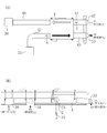
- FIG. 1 is an external view of a ventilation device according to the present embodiment.
- FIG. 2 is an installation diagram of the ventilation device according to the present embodiment.
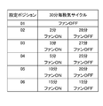
- FIG. 3 is a correspondence table of setting position numbers and ventilation cycles of the ventilation device according to the present embodiment.
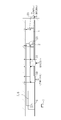
- FIG. 4 is an installation diagram of a ventilation device and an air conditioner according to Modification 2 of the present embodiment.
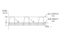
- FIG. 5 is a graph showing the relationship between the fan air volume and the startup time when each fan is set to continuous operation or intermittent operation in the forced ventilation operation of the ventilator according to the present embodiment.
- FIG. 6 is a flowchart at the time of forced ventilation operation in the ventilation device according to the first modification of the present embodiment.
- FIG. 7 is a flowchart at the time of forced ventilation operation in the ventilator according to the second modification of the present embodiment.
- the ventilation apparatus (1) of this embodiment is a total heat exchanger unit of a ceiling embedded duct type. Note that the meanings of the terms “right”, “left”, “upper”, “lower”, “front”, and “back” used in the following description are the meanings of the states shown in FIG. 1 unless otherwise specified.
- the total heat exchanger unit (1) includes a horizontally long and flat rectangular parallelepiped casing (10).
- the right side plate (11) of the casing (10) is provided with one outside air suction duct connection portion (13) and one exhaust duct connection portion (14).
- the outside air suction duct connecting portion (13) is disposed on the back side, and the exhaust duct connecting portion (14) is disposed on the near side.
- the left side plate (12) of the casing (10) is provided with an inside air suction duct connection portion (15) and an air supply duct connection portion (16).
- the inside air suction duct connection portion (15) is disposed on the near side
- the air supply duct connection portion (16) is disposed on the back side.
- the internal space of the casing (10) is divided into an air supply side passage and an exhaust side passage, although not shown.
- the air supply side passage communicates with the openings of the outside air suction duct connection portion (13) and the air supply duct connection portion (16).
- the exhaust side passage communicates with the openings of the inside air suction duct connecting portion (15) and the exhaust duct connecting portion (14).
- An air supply fan (20) is provided in the air supply side passage, and an exhaust fan (21) is provided in the exhaust side passage.
- These fans (20, 21) are each composed of a fan body that is a so-called sirocco fan and a fan motor that drives the fan body.
- the fan motor is provided with a rotation speed switching mechanism for changing the rotation speed in stages, and the rotation speed of the fan can be adjusted by the rotation speed switching mechanism.
- the number of rotations of the fan motor can be changed in three stages.
- a total heat exchanger (22) is provided across the supply side passage and the exhaust side passage.
- This total heat exchanger (22) is formed in a square column shape with a square end surface.
- a flat plate member (not shown) and a corrugated plate member (not shown) are arranged in the longitudinal direction. Are arranged alternately.
- an air supply channel for flowing outdoor air and an exhaust channel for flowing air in a living room are alternately formed with a flat plate member sandwiched between them.
- the cross flow type heat exchanger is configured in which the extending direction and the extending direction of the exhaust passage are orthogonal to each other.
- the air supply passage communicates with the air supply side passage, and the exhaust passage communicates with the exhaust side passage.
- the flat plate member of the total heat exchanger (22) is made of a moisture-permeable material such as paper.
- heat and moisture move from one of the outdoor air flowing through the air supply passage and the air inside the room flowing through the exhaust passage from one to the other. That is, in the total heat exchanger (22), enthalpy is exchanged between humid airs.
- a control box (23) is attached to the side plate on the front side of the casing (10).
- the control box (23) houses a controller (2) which is a control unit for controlling the operation of the air supply fan (20) and the exhaust fan (21).
- the operation controlled by the controller (2) includes the forced ventilation operation that is a feature of the present invention. Details of the forced ventilation operation will be described later.
- the total heat exchanger unit (1) is installed behind the ceiling of the living room.
- An air supply grille (30) having an air supply port and an exhaust grille (31) having an exhaust port are provided on the ceiling.
- One end of the first air supply duct (40) is connected to the air supply grill (30), and the other end is connected to the air supply duct connection (16) of the total heat exchanger unit (1).
- One end of a first exhaust duct (42) is connected to the exhaust grill (31), and the other end is connected to an inside air suction duct connection (15) of the total heat exchanger unit (1).
- a round hood for air supply (32) and a round hood for exhaust (33) are provided on the wall that separates the living room from the outside.
- Each of the round hoods (32, 33) has a vent.
- One end of the second air supply duct (41) is connected to the round hood for air supply (32), and the other end is connected to the outside air suction duct connection part (13) of the total heat exchanger unit (1).
- One end of a second exhaust duct (43) is connected to the round exhaust hood (33), and the other end is connected to an exhaust duct connection (14) of the total heat exchanger unit (1).
- the remote control (34) that is the operation unit is installed in the room.
- the remote controller (34) is used by the user to operate the total heat exchanger unit (1), and is connected to the control controller (2) of the control box (23) by electric wiring.
- the remote controller (34) transmits an operation signal for starting and stopping the operation of the total heat exchanger unit (1) and a rotation speed setting signal for setting the rotation speed of the fan via the electric wiring. It is configured to output to the control controller (2).
- the remote controller (34) is also configured to output to the controller (2) a ventilation cycle signal for changing the ventilation amount during forced ventilation operation described later.
- the above forced ventilation operation is sometimes called a so-called 24-hour ventilation operation.
- the forced ventilation operation is performed by intermittently operating the air supply fan (20) and the exhaust fan (21).
- the ventilation amount of the forced ventilation operation can be changed in five stages as shown in FIG. is there.
- the remote controller (34) when the user inputs the set position number shown in FIG. 3 to the remote controller (34), a ventilation cycle signal corresponding to the set position number is output to the controller (2), Change the ventilation rate during forced ventilation operation.
- an air supply temperature sensor (supply side temperature detection unit) (3) for detecting the temperature of outdoor air flowing into the total heat exchanger unit (1).
- an exhaust temperature sensor (exhaust side temperature detector) for detecting the temperature of the air in the room flowing into the total heat exchanger unit (1) ( 4) is provided.
- the ventilation operation of the total heat exchanger unit (1) includes an arbitrary ventilation operation for arbitrarily ventilating, a ventilation amount that is smaller than the arbitrary ventilation operation, and a ventilation amount that is greater than a predetermined necessary ventilation amount. It is equipped with forced ventilation operation to forcibly ventilate the living room.
- the optional ventilation operation is a so-called normal ventilation operation that is normally performed.
- the forced ventilation operation is a so-called 24-hour ventilation operation.
- the controller (2) When the controller (2) receives a stop signal for stopping the arbitrary ventilation operation, the controller (2) terminates the arbitrary ventilation operation, starts the forced ventilation operation, and receives a start signal for starting the arbitrary ventilation operation. The forced ventilation operation is terminated and the arbitrary ventilation operation is started.
- the controller (2) is configured to be capable of intermittent control for intermittently operating the fans (20, 21) during the forced ventilation operation.
- the user selects one of the air volumes set in three stages by the remote controller (34). Thereafter, when the user turns on the operation switch of the remote controller (34), the rotation speed setting signal corresponding to the selected air volume and the operation signal for starting the operation of the total heat exchanger unit (1) are displayed on the remote controller. (34) is input to the controller (2), and the air supply fan (20) and the exhaust fan (21) start operation with the air volume selected. Then, the outdoor air passes through the air supply passage of the second air supply duct (41) and the total heat exchanger (22) from the air supply round hood (32), and the air supply fan in the casing (10). Inhaled into (20).
- the air in the room passes from the exhaust grill (31) to the exhaust fan (21) in the casing (10) through the first exhaust duct (42) and the exhaust heat passage of the total heat exchanger (22). Inhaled.
- the total heat exchanger (22) heat and moisture move from one of the air flowing in the air supply passage and the air flowing in the exhaust passage to the other, and the temperature and humidity approach each other.
- the outdoor air sucked into the air supply fan (20) is blown out from the air supply fan (20) and flows into the first air supply duct (40).
- the air in the room sucked into the exhaust fan (21) is blown out from the exhaust fan (21) and flows into the second exhaust duct (43).
- the outdoor air that has flowed into the first air supply duct (40) passes through the first air supply duct (40) and is then blown out from the air supply grill (30) into the living room as supply air.
- the air in the room that has flowed into the second exhaust duct (43) passes through the second exhaust duct (43) and is then discharged to the outside as exhaust air from the exhaust round hood (33).
- the operation performed in accordance with the operation command of the remote controller (34) is the optional ventilation operation, and the air in the room is ventilated by this operation.
- the optional ventilation operation ends when the user turns off the operation switch of the remote control (34). Thereafter, the air supply fan (20) and the exhaust fan (21) are not completely stopped, but forced ventilation operation is performed based on the ventilation cycle signal input from the remote controller (34) to the controller (2). That is, the air supply fan (20) and the exhaust fan (21) are operated intermittently.
- the rotational speed of each fan (20, 21) is set to the lowest rotational speed among the three stages.
- the air supply fan (20) and the exhaust fan (21) are operated for 2 minutes and then stopped for 28 minutes. Then, after driving again for 2 minutes, it stops for 28 minutes. This cycle is repeated until the operation switch of the remote controller (34) is turned on.
- the operation in which the air supply fan (20) and the exhaust fan (21) are intermittently blown is a forced ventilation operation. The air in the room will continue to be ventilated even after the end.
- the air supply fan (20) and the exhaust fan (21) can be operated intermittently during forced ventilation operation.
- the ventilation amount at the time of forced ventilation operation can be decreased and power consumption can be reduced.
- the temperature exchange efficiency of the total heat exchanger (22) can be kept lower when these fans (20, 21) are operated intermittently than when they are operated continuously.
- the supply air can be supplied into the living room by controlling the temperature of the supply air so as not to approach the temperature of the air in the living room.
- the ventilation amount in the room in the forced ventilation operation can be freely set by changing the setting position number of the remote controller (34). From this, for example, the ventilation volume in the living room can be set based on the standard defined by the revised Building Standard Law. As a result, a lean ventilation amount can be set for the ventilator, and the amount of operating power during forced ventilation operation can be appropriately suppressed.
- Mode 1 of Embodiment The difference between the present embodiment and the first modification of the embodiment is that the controller (2) is configured so that each fan is based on the detected temperatures of the supply air temperature sensor (3) and the exhaust temperature sensor (4). (20, 21) can be switched between continuous operation and intermittent operation, and a rotation speed switching mechanism dedicated to the continuous operation is provided in the fan motor of each fan (20, 21).
- FIG. 5 is a graph showing the relationship between the fan air volume and the drive time when each of the fans (20, 21) is set to either continuous operation or intermittent operation.
- the intermittent operation has a larger air volume than the continuous operation, but the ventilation amount of both is set to the same value by shortening the operation time of the intermittent operation than the continuous operation.
- this ventilation volume is equal to the ventilation volume calculated from the floor area of this room, the use area of a predetermined building material, etc. based on Japanese law.
- each fan (20, 21) When each fan (20, 21) is set to continuous operation, the fan (20, 21) rotates at a rotation speed slower than the minimum rotation speed during the optional ventilation operation by the rotation speed switching mechanism.
- each fan (20, 21) is continuously operated at an air volume of 80 m 3 / h.
- the temperature exchange efficiency of the total heat exchanger (22) with respect to this air volume is 84%.
- each fan (20, 21) when each fan (20, 21) is set to intermittent operation, the rotation speed of the fan motor of each fan (20, 21) is switched by the rotation speed switching mechanism, and each fan (20, 21) is switched. Operates intermittently at an air volume of 400 m3 / h.
- the temperature exchange efficiency of the total heat exchanger (22) with respect to this air volume is 70%.
- the intermittent operation is performed when it is not desired to bring the air temperature blown into the living room close to the room temperature. Conversely, when it is desired to bring the air temperature blown into the room close to the room temperature, the continuous operation is performed.
- the controller (2) is configured so that the first operation for continuously operating the fans (20, 21) is substantially equal to the ventilation amount per unit time during the first operation. It is configured to be able to switch to a second operation in which both the fans (20, 21) are intermittently operated at a fan rotation speed faster than that in one operation, and to perform a forced ventilation operation.
- FIG. 6 is a flowchart at the time of forced ventilation operation in the first modification.
- the forced ventilation operation is started at the same time as the arbitrary ventilation operation is completed.
- the set temperature Tset is set to 19 ° C.
- Step ST1 is to determine the outdoor season.
- the detected temperature T1 is the inlet temperature on the supply side of the total heat exchanger (22), and is therefore substantially the same as the outdoor temperature. If the detected temperature T1 is 19 ° C. or higher, it is determined as summer, and if the detected temperature T1 is lower than 19 ° C., it is determined as winter. And if the conditions of step ST1 are satisfied, it will be determined as summer and it will move to step ST2, otherwise, it will be determined as winter and will move to step ST3.
- step ST2 it is determined whether or not the detected temperature T1 of the supply air temperature sensor (3) is lower than the detected temperature T2 of the exhaust temperature sensor (4). And if the conditions of step ST2 are satisfy
- step ST2 in the summer, when the outdoor temperature (T1) is lower than the indoor temperature (T2), the outdoor air temperature is not increased by the total heat exchanger (22) as much as possible, and the air is It is better to blow out inside. Therefore, in this case, the fans (20, 21) are intermittently operated (step ST4). As a result, the temperature exchange efficiency of the total heat exchanger (22) is lowered as described above, and the air is blown into the living room without increasing the outdoor air temperature as much as possible with the total heat exchanger (22). be able to.
- the outdoor temperature (T1) is equal to or higher than the indoor temperature (T2)
- the outdoor air temperature should be lowered by the total heat exchanger (22) as much as possible before the air is blown into the indoor room. Good. Therefore, in this case, the fans (20, 21) are continuously operated (step ST5). This increases the temperature exchange efficiency of the total heat exchanger (22) as described above. After the outdoor air temperature is increased as much as possible by the total heat exchanger (22), the air is blown into the living room. be able to.
- step ST3 it is determined whether or not the detected temperature T1 of the supply air temperature sensor (3) is higher than the detected temperature T2 of the exhaust temperature sensor (4). And if the conditions of step ST3 are satisfied, it will move to step ST6 and will make each said fan (20, 21) perform intermittent operation. On the other hand, if the condition of step ST3 is not satisfied, the process proceeds to step ST7 to cause the fans (20, 21) to perform continuous operation.
- step ST3 in the winter season, contrary to the summer season, when the outdoor temperature (T1) is lower than the indoor temperature (T2), the outdoor air temperature is set to the total heat exchanger (22) as much as possible. It is better to blow the air into the living room after raising it. Therefore, in this case, the fans (20, 21) are continuously operated (step ST7). This increases the temperature exchange efficiency of the total heat exchanger (22) as described above. After the outdoor air temperature is increased as much as possible by the total heat exchanger (22), the air is blown into the living room. be able to.
- the fans (20, 21) are intermittently operated (step ST6). This reduces the temperature exchange efficiency of the total heat exchanger (22) as described above, so that the air is blown out into the living room without reducing the outdoor air temperature as much as possible with the total heat exchanger (22). Can be made.
- the fans (20, 21) are intermittently or continuously operated based on the outdoor temperature (T1) and the indoor temperature (T2).
- T1 the outdoor temperature
- T2 the indoor temperature
- the temperature of the air supplied into the living room can be controlled.
- the operation of the air conditioner (5, 6) shown in FIG. 4 is configured to be switchable between a cooling operation and a heating operation.
- a remote controller for air conditioning (7) is provided for the user to operate the air conditioner (5, 6).
- the air conditioner remote controller (7) is connected to an air conditioner control board (8) for controlling the operation of the air conditioner (5, 6) by electric wiring.
- the air conditioning control board (8) and the total heat exchanger unit control controller (2) are connected by electrical wiring.
- the air conditioner remote control (7) includes an operation signal for starting or stopping the operation of the air conditioner (5, 6), an operation setting signal for setting the cooling operation mode or the heating operation mode, and each operation mode.
- a set temperature signal for setting the set temperature is output to the air conditioning control board (8) via the electrical wiring. These signals are also output from the air conditioning control board (8) to the controller (2) for the total heat exchanger unit.
- the operation setting corresponding to the selected operation mode is set.
- the signal and the operation signal for starting the operation of the air conditioner (5, 6) are input to the air conditioning control board (8) and the controller (2) for the total heat exchanger unit.
- the air conditioner (5, 6) starts operation in the selected operation mode, and at the same time, the total heat exchanger unit (1) starts arbitrary ventilation operation.
- the operation switch of the air conditioner remote control (7) is turned OFF, the operation of the air conditioner (5, 6) stops and at the same time, the operation of the total heat exchanger unit (1) is switched from the optional ventilation operation to the forced ventilation operation. Continue ventilation operation.
- the total heat exchanger unit (1) is operated in conjunction with the air conditioner (5, 6).
- FIG. 7 is a flowchart at the time of forced ventilation operation in Modification 2.
- the forced ventilation operation starts as described above.
- step ST11 of FIG. 7 it is determined whether or not the operation mode of the air conditioner (5, 6) is a cooling operation. And if it determines with air_conditionaing
- the outdoor is in the summer or winter in the operation mode setting state of the air conditioning remote controller (7). If the operation mode of the air conditioner (5, 6) is cooling, it is determined as summer, and if it is heated, it is determined as winter.
- step ST12 unlike the first modification, it is determined whether or not the detected temperature T1 of the supply air temperature sensor (3) is lower than the cooling set temperature of the air conditioner (5, 6).
- the outdoor temperature (T1) is lower than the cooling set temperature
- the outdoor air temperature should be blown into the living room without raising the outdoor air temperature as much as possible by the total heat exchanger (22). Therefore, in this case, the fans (20, 21) are intermittently operated.
- the temperature exchange efficiency of the total heat exchanger (22) is lowered as described above, and the air is blown into the living room without increasing the outdoor air temperature as much as possible with the total heat exchanger (22). be able to.
- the outdoor temperature (T1) when the outdoor temperature (T1) is equal to or higher than the cooling set temperature, the outdoor air temperature should be lowered by the total heat exchanger (22) as much as possible before the air is blown into the living room. Therefore, in this case, the fans (20, 21) are continuously operated. This increases the temperature exchange efficiency of the total heat exchanger (22) as described above, so that the outdoor air temperature is lowered as much as possible by the total heat exchanger (22), and then the air is blown into the living room. be able to.
- step ST13 it is determined whether or not the detected temperature T1 of the supply air temperature sensor (3) is higher than the heating set temperature of the air conditioner (5, 6).
- the outdoor temperature (T1) is higher than the heating set temperature, the outdoor air temperature should be blown out into the living room without being lowered by the total heat exchanger (22) as much as possible. Therefore, in this case, the fans (20, 21) are intermittently operated. This reduces the temperature exchange efficiency of the total heat exchanger (22) as described above, so that the outdoor air temperature is blown into the living room without being lowered by the total heat exchanger (22) as much as possible. be able to.
- the fans (20, 21) are intermittently or continuously operated based on the outdoor temperature (T1) and the set temperature of the air conditioner (5, 6). By controlling, the temperature of the air supplied into the living room can be controlled.
- the ventilation device constitutes a ceiling-embedded duct-type total heat exchanger unit (1).
- the ventilation device of the present invention is not limited to the total heat exchanger unit (1), and may be, for example, a ceiling-embedded cassette type total heat exchanger unit.
- this cassette type total heat exchanger unit is provided with an air outlet and a suction port on the bottom surface of the casing (10). In this case, it is possible to ventilate the living room without providing the air supply grill (30) and the exhaust grill (31).
- the air supply fan (20) and the exhaust fan (21) are intermittently operated simultaneously.
- the present invention is not limited to this, and both fans (20, 21) may be operated differently.
- the driving time of the air supply fan (20) is longer, the room can be set to a positive pressure.
- the interior of the room can be set to a negative pressure.
- the air of the negative room can be prevented from flowing into the adjacent room.
- the present invention is useful for a ventilation device that ventilates a living room.
Landscapes
- Engineering & Computer Science (AREA)
- Chemical & Material Sciences (AREA)
- Combustion & Propulsion (AREA)
- Mechanical Engineering (AREA)
- General Engineering & Computer Science (AREA)
- Physics & Mathematics (AREA)
- Fluid Mechanics (AREA)
- Signal Processing (AREA)
- Fuzzy Systems (AREA)
- Mathematical Physics (AREA)
- Human Computer Interaction (AREA)
- Air Conditioning Control Device (AREA)
- Ventilation (AREA)
Abstract
Description
図1及び図2に示すように、本実施形態の換気装置(1)は、天井埋込ダクト形の全熱交換器ユニットである。なお、以下の説明で用いる「右」「左」「上」「下」「手前」「奥」という語句の意味は、特にことわらない限り、いずれも図1に示す状態の意味である。
使用者が、リモコン(34)で3段階に設定された風量のうちの何れかを選択する。その後、使用者が、リモコン(34)の運転スイッチをONすると、その選択した風量に対応する回転速度設定信号と全熱交換器ユニット(1)の運転を開始するための運転信号が、上記リモコン(34)から制御コントローラ(2)に入力され、給気ファン(20)及び排気ファン(21)が選択した風量で運転を開始する。すると、屋外の空気は上記給気用丸型フード(32)から第2給気ダクト(41)及び全熱交換器(22)の給気流路を通って上記ケーシング(10)内の給気ファン(20)に吸い込まれる。一方、居室内の空気は上記排気グリル(31)から第1排気ダクト(42)及び全熱交換器(22)の排気流路を通って上記ケーシング(10)内の上記排気ファン(21)に吸い込まれる。尚、上記全熱交換器(22)において、給気通路を流れる空気及び排気通路を流れる空気のうちの一方から他方へ熱と水分とが移動して、互いに温度と湿度が近づく。
本実施形態では、従来とは違い、強制換気運転時に上記給気ファン(20)及び上記排気ファン(21)を間欠的に運転することが可能に構成されている。これにより、これらのファン(20,21)を連続的に運転する場合に比べて、強制換気運転時の換気量を少なくして消費電力量を低減することができる。
本実施形態と、実施形態の変形例1との違いは、上記制御コントローラ(2)が、上記給気温度センサ(3)及び上記排気温度センサ(4)の検出温度に基づいて、上記各ファン(20,21)を連続運転と間欠運転とを切り換えることができる点と、その連続運転専用の回転数切換機構が上記各ファン(20,21)のファンモータに設けられている点である。
本実施形態と、実施形態の変形例2との違いは、全熱交換器ユニット(1)が居室内に設置された冷房機構及び暖房機構である空調機(5,6)と連動しながら運転する点である。
上記実施形態については、以下のような構成としてもよい。
2 制御コントローラ(制御手段)
3 給気温度センサ(給気側温度検知部)
4 排気温度センサ(排気側温度検知部)
10 ケーシング
20 給気ファン
21 排気ファン
22 全熱交換器
34 リモコン(操作部)
Claims (10)
- 屋外の空気を供給空気として居室内に供給する給気ファン(20)と、居室内の空気を排出空気として屋外に排出する排気ファン(21)と、上記供給空気が流れる給気流路及び上記排出空気が流れる排気流路を有する全熱交換器(22)とを備え、上記居室内の空気を換気する換気運転を行う換気装置であって、
上記換気運転は、任意に換気を行うための任意換気運転と、該任意換気運転よりも少ない換気量で且つ所定の必要換気量以上の換気量で上記居室を強制換気する強制換気運転とを有する一方、
上記任意換気運転を停止する停止信号を受けると、上記任意換気運転を終了させて上記強制換気運転を開始させ、上記任意換気運転を開始する開始信号を受けると、上記強制換気運転を終了させて上記任意換気運転を開始させる制御部(2)を備え、
該制御部(2)は、上記強制換気運転時に上記両ファン(20,21)を間欠的に動作させる間欠制御が可能に構成されている
ことを特徴とする換気装置。 - 請求項1において、
上記両ファン(20,21)は風量可変に構成され、
上記制御部(2)は、上記両ファン(20,21)を連続的に動作させる第1動作と、該第1動作時による単位時間あたりの換気量と実質的に等しくなるように第1動作時よりも速いファン回転速度で上記両ファン(20,21)を間欠的に動作させる第2動作とに切換可能に構成されて強制換気運転を実行するように構成されている
ことを特徴とする換気装置。 - 請求項2において、
上記全熱交換器(22)の供給空気の入口温度T1を検知する給気側温度検知部(3)と、上記全熱交換器(22)の排出空気の入口温度T2を検知する排気側温度検知部(4)とを備え、
上記制御部(2)は、上記給気側温度検知部(3)の検出値が所定値Tset以上であって給気側温度検知部(3)の検出値が排気側温度検知部(4)の検出値よりも小さい場合には第2動作に設定し、上記給気側温度検知部(3)の検出値が所定値Tset以上であって給気側温度検知部(3)の検出値が排気側温度検知部(4)の検出値以上の場合には第1動作に設定するように構成されている
ことを特徴とする換気装置。 - 請求項2において、
上記全熱交換器(22)の供給空気の入口温度T1を検知する給気側温度検知部(3)と、上記全熱交換器(22)の排出空気の入口温度T2を検知する排気側温度検知部(4)とを備え、
上記制御部(2)は、上記給気側温度検知部(3)の検出値が所定値Tsetよりも小さい場合であって給気側温度検知部(3)の検出値が排気側温度検知部(4)の検出値以下の場合には第1動作に設定し、上記給気側温度検知部(3)の検出値が所定値Tsetよりも小さい場合であって給気側温度検知部(3)の検出値が排気側温度検知部(4)の検出値より大きい場合には第2動作に設定するように構成されている
ことを特徴とする換気装置。 - 請求項2において、
上記居室内の温度が冷房設定温度となるように居室内を冷房する冷房機構(5)を備え、
上記制御部(2)は、上記給気側温度検知部(3)で検知した供給空気の入口温度T1が上記冷房設定温度以上の場合には第1動作に設定し、上記供給空気の入口温度T1が上記冷房設定温度よりも小さい場合には第2動作に設定するように構成されている
ことを特徴とする換気装置。 - 請求項2において、
上記居室内の温度が暖房設定温度となるように居室内を暖房する暖房機構(6)を備え、
上記制御部(2)は、上記給気側温度検知部(3)で検知した供給空気の入口温度T1が上記暖房設定温度以下の場合には第1動作に設定し、上記供給空気の入口温度T1が上記暖房設定温度より大きい場合には第2動作に設定するように構成されている
ことを特徴とする換気装置。 - 請求項1から6の何れか1つにおいて、
上記制御部(2)は、上記強制換気運転時における各ファン(20,21)の間欠運転時間に占める駆動時間及び停止時間の割合が変更可能に構成されている
ことを特徴とする換気装置。 - 請求項5において、
上記冷房機構(5)の運転が停止すると上記冷房機構(5)から上記制御部(2)へ停止信号が出力され、上記冷房機構(5)の運転が開始すると上記冷房機構(5)から上記制御部(2)へ開始信号が出力されるように、上記冷房機構(5)と上記制御部(2)とが電気的に接続されている
ことを特徴とする換気装置。 - 請求項6において、
上記暖房機構(6)の運転が停止すると上記暖房機構(6)から上記制御部(2)へ停止信号が出力され、上記暖房機構(6)の運転が開始すると上記暖房機構(6)から上記制御部(2)へ開始信号が出力されるように、上記暖房機構(6)と上記制御部(2)とが電気的に接続されている
ことを特徴とする換気装置。 - 請求項1から9の何れか1つにおいて、
使用者が操作する操作部(34)を備え、
上記操作部(34)から上記制御部(2)に向かって上記停止信号及び上記開始信号が出力されるように、上記操作部(34)と上記制御部(2)とが電気的に接続されている
ことを特徴とする換気装置。
Priority Applications (6)
| Application Number | Priority Date | Filing Date | Title |
|---|---|---|---|
| EP09766441.1A EP2309196B1 (en) | 2008-06-18 | 2009-06-18 | Ventilation device |
| KR1020117001204A KR101298816B1 (ko) | 2008-06-18 | 2009-06-18 | 환기장치 |
| AU2009261383A AU2009261383B2 (en) | 2008-06-18 | 2009-06-18 | Ventilator |
| ES09766441T ES2717342T3 (es) | 2008-06-18 | 2009-06-18 | Dispositivo de ventilación |
| US12/999,636 US20110111689A1 (en) | 2008-06-18 | 2009-06-18 | Ventilator |
| CN200980122174.2A CN102057226B (zh) | 2008-06-18 | 2009-06-18 | 换气装置 |
Applications Claiming Priority (2)
| Application Number | Priority Date | Filing Date | Title |
|---|---|---|---|
| JP2008158797 | 2008-06-18 | ||
| JP2008-158797 | 2008-06-18 |
Publications (1)
| Publication Number | Publication Date |
|---|---|
| WO2009153993A1 true WO2009153993A1 (ja) | 2009-12-23 |
Family
ID=41433911
Family Applications (1)
| Application Number | Title | Priority Date | Filing Date |
|---|---|---|---|
| PCT/JP2009/002772 Ceased WO2009153993A1 (ja) | 2008-06-18 | 2009-06-18 | 換気装置 |
Country Status (8)
| Country | Link |
|---|---|
| US (1) | US20110111689A1 (ja) |
| EP (1) | EP2309196B1 (ja) |
| JP (1) | JP4483995B2 (ja) |
| KR (1) | KR101298816B1 (ja) |
| CN (1) | CN102057226B (ja) |
| AU (1) | AU2009261383B2 (ja) |
| ES (1) | ES2717342T3 (ja) |
| WO (1) | WO2009153993A1 (ja) |
Families Citing this family (23)
| Publication number | Priority date | Publication date | Assignee | Title |
|---|---|---|---|---|
| KR101758269B1 (ko) * | 2010-07-30 | 2017-07-26 | 엘지전자 주식회사 | 환기장치의 제어방법 |
| JP5538270B2 (ja) * | 2011-02-24 | 2014-07-02 | 三菱電機株式会社 | 熱交換換気装置 |
| CN102562628A (zh) * | 2012-02-22 | 2012-07-11 | 罗顺春 | 一种双向同步换气扇 |
| CN103542488A (zh) * | 2012-07-16 | 2014-01-29 | 李一平 | 套管式排风机 |
| JP2014074554A (ja) * | 2012-10-05 | 2014-04-24 | Mitsubishi Electric Corp | 換気システム、換気方法、換気制御装置及びプログラム |
| WO2015079673A1 (ja) | 2013-11-26 | 2015-06-04 | パナソニックIpマネジメント株式会社 | 給排型換気装置 |
| KR102252725B1 (ko) * | 2014-10-23 | 2021-05-17 | 세메스 주식회사 | 기판 지지용 핀 |
| CN106152374B (zh) * | 2015-03-25 | 2020-05-05 | 大金工业株式会社 | 空调室内机的控制方法及空调室内机 |
| JP6497195B2 (ja) | 2015-04-28 | 2019-04-10 | ダイキン工業株式会社 | 空調装置 |
| JP6448470B2 (ja) * | 2015-05-28 | 2019-01-09 | 三菱電機株式会社 | 熱交換換気装置 |
| JP6545554B2 (ja) * | 2015-07-17 | 2019-07-17 | リンナイ株式会社 | 燃焼装置 |
| JP6061003B1 (ja) * | 2015-08-28 | 2017-01-18 | ダイキン工業株式会社 | コンテナ用冷凍装置 |
| CN106610083A (zh) * | 2015-10-21 | 2017-05-03 | 广东美的制冷设备有限公司 | 空调热交换风速的控制方法及装置 |
| CN105258296B (zh) * | 2015-10-29 | 2018-10-09 | 广东美的制冷设备有限公司 | 空调器控制方法及系统、空调器 |
| CN105805877B (zh) * | 2016-05-04 | 2018-11-09 | 珠海格力电器股份有限公司 | 换气装置及其控制方法和空调器 |
| WO2018140330A1 (en) * | 2017-01-29 | 2018-08-02 | Ventacity Systems Inc. | Systems and methods for providing on-demand ventilation management |
| CN110506184B (zh) * | 2017-03-31 | 2021-07-06 | 松下知识产权经营株式会社 | 换气系统、热交换型换气装置 |
| US10921766B2 (en) * | 2019-06-17 | 2021-02-16 | Broan-Nutone Llc | Energy monitoring and reporting system for a ventilation unit |
| JP7292240B2 (ja) * | 2020-04-08 | 2023-06-16 | 三菱電機株式会社 | 換気送風機および換気送風機システム |
| JP7197811B2 (ja) * | 2021-02-26 | 2022-12-28 | ダイキン工業株式会社 | 換気システム |
| WO2023007696A1 (ja) * | 2021-07-30 | 2023-02-02 | 三菱電機株式会社 | 換気空気調和システム |
| US12281804B2 (en) | 2021-08-13 | 2025-04-22 | Goodman Global Group, Inc. | Air management system for a heating, ventilation, and air-conditioning system |
| WO2023062711A1 (ja) * | 2021-10-12 | 2023-04-20 | 三菱電機株式会社 | 換気制御システム |
Citations (3)
| Publication number | Priority date | Publication date | Assignee | Title |
|---|---|---|---|---|
| JP2002039578A (ja) * | 2000-07-21 | 2002-02-06 | Shimizu Corp | 省エネ型24時間換気システム |
| JP2005337647A (ja) | 2004-05-31 | 2005-12-08 | Toshiba Corp | 住宅設備制御装置 |
| JP2007100983A (ja) * | 2005-09-30 | 2007-04-19 | Nitta Ind Corp | 全熱交換器の制御装置、全熱交換装置及び全熱交換器の制御用プログラム |
Family Cites Families (12)
| Publication number | Priority date | Publication date | Assignee | Title |
|---|---|---|---|---|
| JP3372792B2 (ja) * | 1996-11-18 | 2003-02-04 | 株式会社エコ・トゥエンティーワン | 電子冷蔵庫 |
| JPH11190542A (ja) * | 1997-12-26 | 1999-07-13 | Natl House Ind Co Ltd | 住宅の換気システム |
| US6176305B1 (en) * | 1998-11-09 | 2001-01-23 | Building Performance Equipment Inc. | Ventilator system and method |
| US6481635B2 (en) * | 2000-07-21 | 2002-11-19 | Gun Valley Temperature Controls Llc | Environmental control method |
| JP3744409B2 (ja) * | 2001-11-14 | 2006-02-08 | ダイキン工業株式会社 | 熱交換器ユニット |
| CN1217136C (zh) * | 2001-11-19 | 2005-08-31 | 乐金电子(天津)电器有限公司 | 换气装置的电热交换器 |
| JP4228194B2 (ja) * | 2002-12-17 | 2009-02-25 | 株式会社富士通ゼネラル | 空気調和機の制御方法 |
| KR20050055105A (ko) * | 2003-12-05 | 2005-06-13 | 엘지전자 주식회사 | 환기 장치를 구비한 공기 조화기 및 그 운용 방법 |
| JP3757976B2 (ja) * | 2004-04-15 | 2006-03-22 | ダイキン工業株式会社 | 熱交換ユニット |
| JP4507995B2 (ja) * | 2005-06-14 | 2010-07-21 | パナソニック株式会社 | 熱交換機器 |
| JP2007101077A (ja) * | 2005-10-05 | 2007-04-19 | Daiwa House Ind Co Ltd | 24時間換気システム |
| KR101474498B1 (ko) * | 2008-06-23 | 2014-12-23 | 삼성전자 주식회사 | 환기 장치 및 그 제어 방법 |
-
2009
- 2009-06-18 US US12/999,636 patent/US20110111689A1/en not_active Abandoned
- 2009-06-18 WO PCT/JP2009/002772 patent/WO2009153993A1/ja not_active Ceased
- 2009-06-18 KR KR1020117001204A patent/KR101298816B1/ko not_active Expired - Fee Related
- 2009-06-18 AU AU2009261383A patent/AU2009261383B2/en active Active
- 2009-06-18 JP JP2009144955A patent/JP4483995B2/ja active Active
- 2009-06-18 ES ES09766441T patent/ES2717342T3/es active Active
- 2009-06-18 CN CN200980122174.2A patent/CN102057226B/zh active Active
- 2009-06-18 EP EP09766441.1A patent/EP2309196B1/en active Active
Patent Citations (3)
| Publication number | Priority date | Publication date | Assignee | Title |
|---|---|---|---|---|
| JP2002039578A (ja) * | 2000-07-21 | 2002-02-06 | Shimizu Corp | 省エネ型24時間換気システム |
| JP2005337647A (ja) | 2004-05-31 | 2005-12-08 | Toshiba Corp | 住宅設備制御装置 |
| JP2007100983A (ja) * | 2005-09-30 | 2007-04-19 | Nitta Ind Corp | 全熱交換器の制御装置、全熱交換装置及び全熱交換器の制御用プログラム |
Non-Patent Citations (1)
| Title |
|---|
| See also references of EP2309196A4 |
Also Published As
| Publication number | Publication date |
|---|---|
| JP2010025539A (ja) | 2010-02-04 |
| EP2309196A1 (en) | 2011-04-13 |
| US20110111689A1 (en) | 2011-05-12 |
| JP4483995B2 (ja) | 2010-06-16 |
| CN102057226A (zh) | 2011-05-11 |
| ES2717342T3 (es) | 2019-06-20 |
| AU2009261383B2 (en) | 2013-05-02 |
| CN102057226B (zh) | 2016-02-10 |
| KR101298816B1 (ko) | 2013-08-23 |
| EP2309196A4 (en) | 2017-03-22 |
| KR20110031332A (ko) | 2011-03-25 |
| EP2309196B1 (en) | 2018-12-26 |
| AU2009261383A1 (en) | 2009-12-23 |
Similar Documents
| Publication | Publication Date | Title |
|---|---|---|
| JP4483995B2 (ja) | 換気装置 | |
| JP5312055B2 (ja) | 空気調和システム | |
| US20220268460A1 (en) | Air conditioning system | |
| CN104136857A (zh) | 热交换式换气装置 | |
| CN101631994B (zh) | 空调系统及其控制方法 | |
| JP5237782B2 (ja) | 熱交換型換気装置 | |
| JP5022026B2 (ja) | デシカント空調装置 | |
| JP3959181B2 (ja) | 熱交換換気システム | |
| JP4619983B2 (ja) | 空気調和機 | |
| JP2022021450A (ja) | 空気浄化機能付き熱交換形換気装置 | |
| CN100410592C (zh) | 空调装置 | |
| JP3723167B2 (ja) | 空調用室内ユニットおよびこれを備えた空気調和機 | |
| CN115335643B (zh) | 换气空气调节系统 | |
| JP7507342B2 (ja) | 空気浄化装置 | |
| JP2004003837A (ja) | 空気調和装置 | |
| JP2024076802A (ja) | 空気調和装置 | |
| JP2007187334A (ja) | 空気調和機 | |
| JP2005164114A (ja) | 浴室用空調装置 | |
| JP2010101600A (ja) | 空調システム | |
| JP4683056B2 (ja) | 空気調和機の室内機 | |
| JP2000074446A (ja) | 熱交換換気システム | |
| CN116951579B (zh) | 空调器 | |
| JP4282499B2 (ja) | 空気調和装置 | |
| JP2025059824A (ja) | 空調システム | |
| JP4483944B2 (ja) | 空気調和機 |
Legal Events
| Date | Code | Title | Description |
|---|---|---|---|
| WWE | Wipo information: entry into national phase |
Ref document number: 200980122174.2 Country of ref document: CN |
|
| 121 | Ep: the epo has been informed by wipo that ep was designated in this application |
Ref document number: 09766441 Country of ref document: EP Kind code of ref document: A1 |
|
| WWE | Wipo information: entry into national phase |
Ref document number: 12999636 Country of ref document: US Ref document number: 2009261383 Country of ref document: AU |
|
| NENP | Non-entry into the national phase |
Ref country code: DE |
|
| WWE | Wipo information: entry into national phase |
Ref document number: 2009766441 Country of ref document: EP |
|
| ENP | Entry into the national phase |
Ref document number: 20117001204 Country of ref document: KR Kind code of ref document: A |
|
| ENP | Entry into the national phase |
Ref document number: 2009261383 Country of ref document: AU Date of ref document: 20090618 Kind code of ref document: A |