WO2009154172A1 - 通信制御システム、通信制御方法、呼制御サーバ装置および呼制御プログラム - Google Patents
通信制御システム、通信制御方法、呼制御サーバ装置および呼制御プログラム Download PDFInfo
- Publication number
- WO2009154172A1 WO2009154172A1 PCT/JP2009/060882 JP2009060882W WO2009154172A1 WO 2009154172 A1 WO2009154172 A1 WO 2009154172A1 JP 2009060882 W JP2009060882 W JP 2009060882W WO 2009154172 A1 WO2009154172 A1 WO 2009154172A1
- Authority
- WO
- WIPO (PCT)
- Prior art keywords
- home
- information
- connection destination
- destination information
- communication
- Prior art date
- Legal status (The legal status is an assumption and is not a legal conclusion. Google has not performed a legal analysis and makes no representation as to the accuracy of the status listed.)
- Ceased
Links
Images









Classifications
-
- H—ELECTRICITY
- H04—ELECTRIC COMMUNICATION TECHNIQUE
- H04M—TELEPHONIC COMMUNICATION
- H04M7/00—Arrangements for interconnection between switching centres
- H04M7/0024—Services and arrangements where telephone services are combined with data services
- H04M7/003—Click to dial services
-
- G—PHYSICS
- G06—COMPUTING OR CALCULATING; COUNTING
- G06Q—INFORMATION AND COMMUNICATION TECHNOLOGY [ICT] SPECIALLY ADAPTED FOR ADMINISTRATIVE, COMMERCIAL, FINANCIAL, MANAGERIAL OR SUPERVISORY PURPOSES; SYSTEMS OR METHODS SPECIALLY ADAPTED FOR ADMINISTRATIVE, COMMERCIAL, FINANCIAL, MANAGERIAL OR SUPERVISORY PURPOSES, NOT OTHERWISE PROVIDED FOR
- G06Q30/00—Commerce
- G06Q30/02—Marketing; Price estimation or determination; Fundraising
-
- H—ELECTRICITY
- H04—ELECTRIC COMMUNICATION TECHNIQUE
- H04L—TRANSMISSION OF DIGITAL INFORMATION, e.g. TELEGRAPHIC COMMUNICATION
- H04L12/00—Data switching networks
- H04L12/02—Details
- H04L12/14—Charging, metering or billing arrangements specially adapted for data communications, e.g. authentication, authorisation and accounting [AAA] framework
-
- H—ELECTRICITY
- H04—ELECTRIC COMMUNICATION TECHNIQUE
- H04L—TRANSMISSION OF DIGITAL INFORMATION, e.g. TELEGRAPHIC COMMUNICATION
- H04L12/00—Data switching networks
- H04L12/02—Details
- H04L12/14—Charging, metering or billing arrangements specially adapted for data communications, e.g. authentication, authorisation and accounting [AAA] framework
- H04L12/1453—Methods or systems for payment or settlement of the charges for data transmission involving significant interaction with the data transmission network
- H04L12/1457—Methods or systems for payment or settlement of the charges for data transmission involving significant interaction with the data transmission network using an account
-
- H—ELECTRICITY
- H04—ELECTRIC COMMUNICATION TECHNIQUE
- H04L—TRANSMISSION OF DIGITAL INFORMATION, e.g. TELEGRAPHIC COMMUNICATION
- H04L12/00—Data switching networks
- H04L12/02—Details
- H04L12/14—Charging, metering or billing arrangements specially adapted for data communications, e.g. authentication, authorisation and accounting [AAA] framework
- H04L12/1485—Tariff-related aspects
-
- H—ELECTRICITY
- H04—ELECTRIC COMMUNICATION TECHNIQUE
- H04L—TRANSMISSION OF DIGITAL INFORMATION, e.g. TELEGRAPHIC COMMUNICATION
- H04L65/00—Network arrangements, protocols or services for supporting real-time applications in data packet communication
- H04L65/10—Architectures or entities
- H04L65/102—Gateways
- H04L65/1033—Signalling gateways
- H04L65/1036—Signalling gateways at the edge
-
- H—ELECTRICITY
- H04—ELECTRIC COMMUNICATION TECHNIQUE
- H04L—TRANSMISSION OF DIGITAL INFORMATION, e.g. TELEGRAPHIC COMMUNICATION
- H04L65/00—Network arrangements, protocols or services for supporting real-time applications in data packet communication
- H04L65/10—Architectures or entities
- H04L65/1045—Proxies, e.g. for session initiation protocol [SIP]
-
- H—ELECTRICITY
- H04—ELECTRIC COMMUNICATION TECHNIQUE
- H04L—TRANSMISSION OF DIGITAL INFORMATION, e.g. TELEGRAPHIC COMMUNICATION
- H04L65/00—Network arrangements, protocols or services for supporting real-time applications in data packet communication
- H04L65/1066—Session management
- H04L65/1069—Session establishment or de-establishment
-
- H—ELECTRICITY
- H04—ELECTRIC COMMUNICATION TECHNIQUE
- H04L—TRANSMISSION OF DIGITAL INFORMATION, e.g. TELEGRAPHIC COMMUNICATION
- H04L65/00—Network arrangements, protocols or services for supporting real-time applications in data packet communication
- H04L65/1066—Session management
- H04L65/1083—In-session procedures
- H04L65/1094—Inter-user-equipment sessions transfer or sharing
-
- H—ELECTRICITY
- H04—ELECTRIC COMMUNICATION TECHNIQUE
- H04M—TELEPHONIC COMMUNICATION
- H04M15/00—Arrangements for metering, time-control or time indication ; Metering, charging or billing arrangements for voice wireline or wireless communications, e.g. VoIP
-
- H—ELECTRICITY
- H04—ELECTRIC COMMUNICATION TECHNIQUE
- H04M—TELEPHONIC COMMUNICATION
- H04M15/00—Arrangements for metering, time-control or time indication ; Metering, charging or billing arrangements for voice wireline or wireless communications, e.g. VoIP
- H04M15/63—Arrangements for metering, time-control or time indication ; Metering, charging or billing arrangements for voice wireline or wireless communications, e.g. VoIP based on the content carried by the session initiation protocol [SIP] messages
-
- H—ELECTRICITY
- H04—ELECTRIC COMMUNICATION TECHNIQUE
- H04M—TELEPHONIC COMMUNICATION
- H04M15/00—Arrangements for metering, time-control or time indication ; Metering, charging or billing arrangements for voice wireline or wireless communications, e.g. VoIP
- H04M15/82—Criteria or parameters used for performing billing operations
- H04M15/8292—Charging for signaling or unsuccessful connection
Definitions
- the present invention relates to a communication control system and communication for connecting the IP communication device in a home network composed of a home device for performing various communications and an IP communication device, and an external device installed outside the home network.
- the present invention relates to a control method, a call control server device, and a call control program.
- Patent Document 1 Japanese Patent Laid-Open No. 10-336349 discloses a Click-To-Dial system that can make a call (telephone) call with a simple operation by clicking a call button from a Web browser. Yes.
- a system comprising a PC installed with a dedicated web browser with a dedicated software having a function of transmitting to a telephone, and a telephone A connected to the PC.
- the telephone number of the store or the like that he wants to call is obtained from the web page, and the obtained telephone number is entered in the “phone number” input area of the dedicated web browser and the “call button” is clicked.
- the dedicated Web browser makes a call to the connected telephone A, and when the user responds to the telephone A (when on-hook), it makes a call to the telephone number entered by the user.
- the present invention has been made in view of the above, and provides a communication control system, a communication control method, a call control server device, and a call control program that can be easily connected without using special software.
- the purpose is to provide.
- the present invention is installed outside the home network and the IP communication device in the home network composed of a home device that performs various communications and an IP communication device.
- a communication control system for connecting to an outside device, and an in-house information that stores an identifier for uniquely identifying the in-home device and in-home connection destination information indicating information for connecting to the IP communication device in association with each other A storage unit, an out-of-home information storage unit that stores a device ID that uniquely identifies the out-of-home device and out-of-home connection destination information indicating information for connecting to the out-of-home device, and the in-home device
- an access response unit that transmits a device ID stored in the outside information storage unit to the in-home device, and a device that is transmitted by the access response unit.
- the out-of-home information acquisition means for acquiring out-of-home connection destination information corresponding to the notified device ID from the out-of-home information storage means, and the access
- the home connection destination information stored in the home information storage unit is specified in association with the identifier of the selected home device.
- the in-home connection destination information specified by the in-home information specifying means Using the in-home information specifying means, the in-home connection destination information specified by the in-home information specifying means, the first sending means for sending to the IP communication device, and the first sending means Second response means for transmitting to the outside device using the outside connection destination information acquired by the outside information acquisition means when receiving a response from the IP communication device; Establishing a connection between the IP communication device transmitted by the first transmission unit and the external device transmitted by the second transmission unit when a response is received from the external device transmitted by the transmission unit And a connection establishment means.
- the present invention provides a home network configured with a home device that performs various communications and an IP communication device, a Web server device that provides content to the home device, and a solicitation of the content to a customer.
- a service providing server device that provides content information to a home device, an external device that posts content information in content provided to the Web server device, and a call control server device that connects the IP communication device and the external device
- the Web server device is an access that transmits the content to the home device by redirection via the service providing server when the Web server device receives an access request from the home device.
- the response means, the service providing server device, and a device ID for uniquely identifying the outside device When an out-of-home information storage unit that stores information associated with an out-of-home connection information that indicates information for connecting to an out-of-home device and the device ID provided to the content are selected by the in-home device, The remote connection destination information corresponding to the selected device ID is acquired from the external information storage means, and the acquired remote connection destination information is notified to the call control server device by redirection through the internal device. And the call control server device stores in-house information in association with an identifier for uniquely identifying the in-home device and in-home connection destination information indicating information for connecting to the IP communication device.
- the in-home device When the storage means and the outside connection destination information are notified from the service providing server device via the in-home device, the in-home device added by the in-home device when the out-of-home connection destination information is notified Based on the bespoke, using the in-home information specifying means for specifying the in-home connection destination information from the in-home information storage means and the in-home connection destination information specified by the in-home information specifying means, the IP communication device When receiving a response from the first transmitting means for transmitting and the IP communication device transmitted by the first transmitting means, using the outside connection destination information notified from the service providing server device, the home A second transmitter for transmitting to the external device, and an IP communication device transmitted by the first transmitter when receiving a response from the external device transmitted by the second transmitter; Connection establishment means for establishing a connection with the outside device transmitted by the second transmission means.
- a telephone call can be made to an external device on which the advertisement is posted.
- IP communication can be easily connected without using special software.
- the store side can confirm that the inquiry is from the website. Further, for example, it is possible to form an affiliate model on the web by telephone.
- an external device that provides blog parts (content information) to a Web server
- blog parts content information
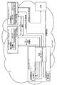
- FIG. 1 is a system configuration diagram illustrating the overall configuration of the communication control system according to the first embodiment.
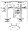
- FIG. 2 is a block diagram illustrating the configuration of the communication control system according to the first embodiment.
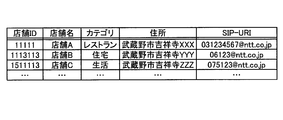
- FIG. 3 is a diagram illustrating an example of information stored in the out-of-home information DB.
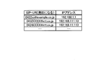
- FIG. 4 is a diagram illustrating an example of information stored in the home information DB.
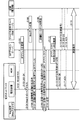
- FIG. 5 is a sequence diagram illustrating the flow of processing by the communication control system according to the first embodiment.
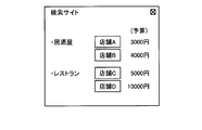
- FIG. 6A is a diagram illustrating a screen example of a Web site on which an advertisement with a store ID added is displayed.
- FIG. 6B is a diagram illustrating an example of a Web site screen displayed on the Web terminal as a call confirmation.
- FIG. 6A is a diagram illustrating a screen example of a Web site on which an advertisement with a store ID added is displayed.
- FIG. 6B is a diagram illustrating an example of a Web site screen displayed on the Web terminal as a
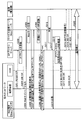
- FIG. 7 is a sequence diagram showing a flow of processing for directly transmitting out-of-home connection destination information from the service providing server to the SIP proxy server.
- FIG. 8 is a sequence diagram illustrating a flow of processing for notification using a certificate such as SAML when transmitting from a service providing server to a SIP proxy server via a Web terminal.
- FIG. 9 is a diagram illustrating an example of added SAML.
- FIG. 10 is a diagram illustrating an example of signature information described in SAML.
- FIG. 11 is a diagram illustrating an overall configuration of a communication control system according to the third embodiment.
- FIG. 12 is a sequence diagram illustrating the flow of processing in the communication control system according to the third embodiment.
- FIG. 13 is a diagram illustrating an example of storing a blog accessed by a Web terminal.
- FIG. 14 is a diagram illustrating an example of storing the number of times a blog accessed by a Web terminal has been PVd.
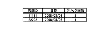
- FIG. 15 is a diagram illustrating an example in which stores clicked on a blog and dates and times are tabulated.
- FIG. 16 is a diagram illustrating an example in which the number of times a blog part is actually selected by the Web terminal is tabulated for each blog.
- FIG. 17 is a diagram illustrating an example in which the number of times actually selected for each store is tabulated.
- FIG. 18 is a diagram illustrating an example in which the stores actually selected and the number of times are totalized within a predetermined period for each blog.
- FIG. 19 is a diagram illustrating an example of storing a call destination and a call destination.
- FIG. 20 is a diagram illustrating an example in which the number of transmissions for each blog is tabulated.
- FIG. 21 is a diagram illustrating an example in which the number of transmissions for each store is tabulated.
- FIG. 22 is a diagram illustrating an example in which the number of calls made for each telephone device is tabulated.
- FIG. 23 is a diagram illustrating an example in which the number of transmissions within a predetermined period for each blog is tabulated.
- FIG. 24 is a diagram illustrating an example in which the number of actual connections for each blog is tabulated.
- FIG. 25 is a diagram illustrating an example in which the number of actual connections for each store is tabulated.
- FIG. 26 is a diagram illustrating an example in which the number of actual connections for each telephone device is tabulated.
- FIG. 27 is a diagram illustrating an example in which the number of stores actually connected and the number of times are counted for each blog within a predetermined period.
- a “communication control system” (an example of a“ communication control system ”described in the claims”) used in this embodiment is a home network composed of a Web terminal, a telephone device, and an HGW (Home Gateway), and a search.
- a service providing server that provides various websites such as a site, a SIP proxy server that performs communication control by SIP communication, and a store (store that stores information on the website provided to the service providing server and solicits customers Are connected to each other via a network.
- a “Web terminal (which is an example of a“ home device ”described in the claims)” is a device such as a personal computer that performs communication such as the Internet using a general Web browser.
- “Telephone device (an example of“ IP communication device ”described in the claims”) is a telephone or softphone that has a numeric keypad such as a VoIP telephone and performs a call connection by specifying a destination by a dial signal. Furthermore, it may be a TV equipped with a Web browser equipped with a remote control or the like.
- HGW (an example of“ data relay device ”described in the claims”) means “192.168.1.1” as the IP address and “0422xx” as the SIP-URI (Session Initiation Protocol-Uniform Resource Identifier).
- @ xxx.co.jp is a device that is communicably connected to a home network and an external network that are set to“ @ xxx.co.jp ”, and interconnects information appliances by performing address conversion and data transfer. Specifically, it is arranged between the Internet and a home network, and has a set-top box such as a home router, protocol conversion, firewall, firewall rule dynamic change function and broadcast reception function. That is, the Web terminal and the telephone device can access the Web site using the same IP address via the HGW.
- a set-top box such as a home router, protocol conversion, firewall, firewall rule dynamic change function and broadcast reception function. That is, the Web terminal and the telephone device can access the Web site using the same IP address via the HGW.
- each device (information home appliance) in the home network is connected using protocols such as DLNA (Digital Living Network Alliance) and UPnP (Universal Plug and Play) which are home appliance standardization technologies.
- various devices such as Hard Disk Recorder and Web browser TV are connected.
- these devices communicate with each other via the HGW when communicating with an external network.
- DLNA Digital Living Network Alliance
- UPnP Universal Plug and Play
- these devices communicate with each other via the HGW when communicating with an external network.
- the Web terminal performs Web communication with a service providing server
- the Web terminal performs NAT conversion in the HGW and communicates with the service providing server using the IP address “192.168.1.1” set in the HGW. Will be performed.
- IPv4 is described as an example, but IPv6 can be similarly processed.
- a notation using a prefix for example, 192.168.1.0/24) can also be used.
- the “service providing server” is a device that provides various websites for access received via a network. For example, Web sites such as a search site, a news site, and a music site are provided.
- the “SIP proxy server (which is an example of a“ call control server device ”recited in the claims)” is a device that connects a plurality of devices using a SIP (Session Initiation Protocol).
- “store an example of“ external device ”described in the claim”) ”provides advertisements for services provided by customers (for example, pubs, restaurants, car sales, etc.) to customers.
- customers are secured by posting on the server website.
- the “store” places an advertisement such as “store name, address, telephone number, service (all-you-can-drink 3000 yen)” on the website of the service providing server as a service provided to the customer. Then, the customer can access the website using a web terminal, browse various advertisements posted on the website, and determine a store that matches his / her requirements.
- FIG. 1 is a system configuration diagram illustrating the overall configuration of the communication control system according to the first embodiment.
- this communication control system is connected to a home network including a Web terminal, a telephone device, and an HGW, a service providing server, a SIP proxy server, and a store via a network.
- the communication control system outlines connecting a telephone device in a home network and a store installed outside the home network.
- the main feature is that a telephone call can be easily connected without using software.
- the home network is connected to a Web terminal, a telephone device, and an HGW that controls various communications with other networks.
- the SIP proxy server stores an identifier for uniquely identifying the Web terminal and in-home connection destination information indicating information for connecting to the telephone device in association with each other in the in-home information DB.
- the in-home information DB includes “IP address indicating an identifier for uniquely identifying a Web terminal and“ SIP-URI ”indicating information for connecting to a telephone device in the home network”. “192.168.1.1, 0422xx@example.co.jp” etc. Note that here, a case where an IP address that is an exact match in IPv4 is used as an identifier will be described.
- the present invention is not limited to this, and for example, a case where a forward match or a correlated IP address in IPv6 is used.
- Any user ID that can be identified, such as a user ID assigned in advance, can be used without being limited thereto.
- the service providing server stores a store ID that uniquely identifies the store (an example of “device ID” described in the claims) in association with device information related to the store in the outside information DB.
- the out-of-home information DB associates “SIP-URI” of the out-of-home device indicating the device information in association with “the store ID that uniquely identifies the store” as the device ID.
- the out-of-home information DB stores “11111, 031234567@ntt.co.jp” or the like as “Store ID, SIP-URI”.
- the store ID stored here is uniquely given in advance by the service providing server by an application from a store that desires to use the website.
- the service providing server when receiving an access request from the Web terminal, transmits the store ID stored in the outside information DB to the Web terminal (see (1) to (2) in FIG. 1). ). More specifically, in the above example, the Web terminal is activated by a user operation, and the URL of the service providing server is input to access the service providing server. Then, the service providing server responds to the Web terminal with a Web site on which an advertisement with the store ID “11111” stored in the outside information DB is displayed. Note that the Web site to which the service providing server responds has not only the above-described store ID “11111” but also a plurality of store IDs added thereto. In other words, this Web site may display a plurality of advertisements like a general search site, and the above-described device information may be added to each of the advertisements.
- the service providing server specifies and acquires device information corresponding to the selected store ID from the outside information DB, and via the Web terminal The acquired device information is notified to the SIP proxy server (see (3) to (5) in FIG. 1).
- the service providing server clicks on the click.
- the service providing server Since the IP address of the Web terminal (HGW) is added at the time of this redirection, the service providing server sets the SIP-URI “031234567@ntt.co.jp” and the IP address “192.168.1.1” of the Web terminal. The SIP proxy server is notified.
- the SIP proxy server specifies the home connection destination information of the Web terminal from the home information DB based on the identifier added by the Web terminal when the device information is notified ((6) in FIG. 1). reference). More specifically, in the above example, when the SIP-URI “031234567@ntt.co.jp” of the store is notified via the Web terminal by the service providing server, the SIP proxy server “the SIP-URI“ 031234567@ntt.co.jp ", based on the IP address" 192.168.1.1 "that is an identifier added by the Web terminal, the SIP-URI" 0422xx@example.co.jp "of the Web terminal Is identified from the home information DB.
- the SIP proxy server makes a call to the telephone device using the specified in-home connection destination information (see (7) in FIG. 1). More specifically, in the above example, the SIP proxy server makes a SIP call to the SIP-URI “0422xx@example.co.jp” (telephone device) specified based on the IP address “192.168.1.1”. After that, a response to the call (for example, on-hook or the like) is received from the call destination (telephone device).
- the SIP proxy server transmits the response to the store using the device information specified by the outside information DB (see (8) in FIG. 1). .
- the SIP proxy server connects the originating telephone device and the originating external device (see (9) in FIG. 1). Specifically, in the above-described example, when a response is received from the calling store, the SIP proxy server establishes a connection between the calling telephone device and the calling store.
- the communication control system calls the store where the advertisement is posted only by clicking an advertisement (external information) displayed on a website accessed using a general web browser.
- the main feature is that it is possible to make a call connection easily without using special software.
- FIG. 2 is a block diagram illustrating the configuration of the communication control system according to the first embodiment. Since the HGW, the Web terminal, the telephone device, and the store have the same configuration as that of a general device, a service providing server and a SIP proxy server having a characteristic function in the present invention will be described here.
- the service providing server 10 includes a communication control I / F unit 11, a storage unit 12, and a control unit 20.
- the communication control I / F unit 11 controls communication related to various information exchanged with other devices connected via a network.
- the communication control I / F unit 11 accepts web access from a web terminal in a home network via the HGW, transmits a website to the web terminal via the HGW, or SIP. SIP-URI is notified to the proxy server 30.
- the storage unit 12 stores network information necessary for various types of communication and data and programs necessary for various types of processing by the control unit 20, and has an out-of-home information DB 13 that is particularly closely related to the present invention.
- the out-of-home information DB 13 is “store ID uniquely identifying a store,“ store name ”indicating a store name,“ category ”to which the store belongs,“ address ”of the store,“ "11111, store A, restaurant, Musashino City Kichijoji XXX, 031234567@ntt.co.jp", etc. as "SIP-URI" ".
- the store ID stored here is uniquely given in advance by the service providing server by an application from a store that desires to use the website.
- the information including the various data and parameters described above can be arbitrarily changed.
- FIG. 3 is a diagram illustrating an example of information stored in the out-of-home information DB.
- the control unit 20 has a control program such as an OS (Operating System), a program that defines various processing procedures, and an internal memory for storing necessary data.
- the control unit 20 is closely related to the present invention. It has the access response part 21 and the outside information acquisition part 22, and performs various processes by these.
- the access response unit 21 When the access response unit 21 receives an access request from the Web terminal, the access response unit 21 transmits the store ID stored in the outside information DB 13 to the Web terminal. Specifically, the access response unit 21 displays an advertisement with the store ID “11111” stored in the out-of-home information DB 13 when the access by the web browser is accepted from the web terminal. Respond to the web terminal with the web site.
- the Web site to which the service providing server responds may include not only the store ID “11111” but also a plurality of store IDs. That is, this website displays a plurality of advertisements like a general search site, and the above-described device information is added to each advertisement.
- the outside information acquisition unit 22 acquires device information corresponding to the selected store ID from the outside information DB 13 when the transmitted store ID is selected by the home device, and the SIP proxy via the home device.
- the server 30 is notified.
- the outside information acquisition unit 22 clicks an advertisement with the store ID “11111” out of a plurality of advertisements displayed on the transmitted website by the web terminal.
- the out-of-home information acquisition unit 22 notifies the SIP proxy server 30 of the identified store as a SIP-URI “031234567@ntt.co.jp” by redirection via a Web terminal.
- the SIP proxy server 30 includes a communication control I / F unit 31, a storage unit 32, and a control unit 40.
- the communication control I / F unit 31 controls communication related to various information exchanged with other devices connected via a network.
- the communication control I / F unit 31 receives a SIP-URI or an IP address from the service providing server 10, or controls communication with a telephone device or store in a home network by SIP.
- the storage unit 32 stores network information necessary for various types of communication and data and programs necessary for various types of processing performed by the control unit 40, and has a home information DB 33 that is particularly closely related to the present invention.
- the home information DB 33 stores an identifier for uniquely identifying the home device and home connection destination information indicating information for connecting to the telephone device in association with each other.
- the in-home information DB 33 includes “an IP address indicating an identifier for uniquely identifying the Web terminal” and information for connecting to the telephone device of the in-home network. “192.168.1.1, 0422xx@example.co.jp” or the like is stored as “SIP-URI”.
- SIP-URI Internet Protocol-URI
- the control unit 40 has an internal memory for storing a control program such as an OS (Operating System), a program that defines various processing procedures, and necessary data, and is particularly closely related to the present invention.
- a control program such as an OS (Operating System)
- OS Operating System
- the home information specifying unit 41, the first transmission unit 42, the second transmission unit 43, and the connection unit 44 are provided, and various processes are executed by these.
- the in-home information specifying unit 41 uses the identifier of the Web terminal based on the identifier added by the Web terminal when the device information is notified.
- the home connection destination information is specified from the home information DB 33.
- the in-home information specifying unit 41 when the service providing server 10 notifies the SIP-URI “031234567@ntt.co.jp” of the store via the Web terminal, -When the URI “031234567@ntt.co.jp” is notified, the SIP-URI “0422xx@example.co.jp” corresponding to the IP address “192.168.1.1” which is an identifier added by the Web terminal It is specified from the information DB 33.
- the first transmission unit 42 transmits to the telephone device using the in-home connection destination information specified by the in-home information specifying unit 41. Specifically, in the above example, the first transmission unit 42 controls communication of SIP transmission to the SIP-URI “0422xx@example.co.jp” based on the IP address “192.168.1.1”. This is performed via the I / F unit 31. Thereafter, the first transmission unit 42 receives a response to the transmission such as on-hook from the transmission destination (telephone device) via the communication control I / F unit 31.
- the second transmission unit 43 When the second transmission unit 43 receives a response from the telephone device transmitted by the first transmission unit 42, the second transmission unit 43 transmits the response to the outside device using the device information specified by the outside information acquisition unit 22. . Specifically, in the above-described example, the second transmission unit 43 is identified and notified by the service providing server 10 when receiving a response from the telephone device transmitted by the first transmission unit 42.
- the SIP transmission to the SIP-URI “031234567@ntt.co.jp” of (store) is performed via the communication control I / F unit 31.
- the 2nd transmission part 43 receives the response with respect to the said transmissions, such as an on-hook, from the transmission destination (store) via the communication control I / F part 31, for example.
- the connecting unit 44 When the connection unit 44 receives a response from the transmitted outside device, the connecting unit 44 connects the transmitted telephone device and the transmitted outside device. Specifically, in the above example, when the connection unit 44 receives a response from the transmitted store, the connection unit 44 selects the telephone device transmitted by the first transmission unit 42 and the store transmitted by the second transmission unit 43. Connecting. Further, the connection unit 44 can connect the store and the telephone device of the home network by using a 3rd party call (RFC 3725) based on the acquired telephone number. Specifically, the connection unit 44 receives the telephone number of the store (for example, SIP-URI) and the telephone number of the telephone device of the home network (for example, SIP-URI) through the service providing server. To do.
- a 3rd party call RFC 3725
- connection unit 44 can recognize the service providing server 10, and the service providing server is connected to the telephone device of the home network to which the Web terminal that accesses the Web site and clicks the store is connected or the store.
- Ten telephone numbers (SIP-URI) can be transmitted as calling numbers.
- FIG. 5 is a sequence diagram illustrating the flow of processing by the communication control system according to the first embodiment.
- the telephone device in the home network uses the “REGISTER message in SIP communication” to the SIP proxy server 30 via the HGW at the timing when the power is turned on or the expiration date of the REGISTER. "Is transmitted (step S101).
- the SIP proxy server 30 Upon receiving this “REGISTER message”, stores the IP address added to the REGISTER message by the HGW in association with the SIP-URI of the telephone device in the in-home information DB 33, and A response of “200 OK message” is transmitted (step S102 and step S103).
- the SIP proxy server 30 stores the IP address of the Web terminal and the SIP-URI of the telephone device in association with each other when the SIP communication “REGISTER message” is received.
- the invention is not limited to this, and may be stored in advance by, for example, an administrator.
- the Web terminal accesses the Web site provided by the service providing server 10 (step S104).
- the service providing server 10 that has received the access transmits, as a response to the received access, a Web site showing an advertisement to which the store ID of the out-of-home information is given (Step S105 and Step S106).
- FIG. 6A is a diagram illustrating a screen example of a Web site on which an advertisement with a store ID added is displayed.
- the Web terminal accepts selection of an advertisement displayed on the received Web site by a user operation (Step S107). Subsequently, the service providing server 10 acquires device information corresponding to the selected advertisement (store ID) from the outside information DB 13 (step S108).
- FIG. 6B is a diagram illustrating an example of a Web site screen displayed on the Web terminal as a call confirmation.
- the service providing server 10 notifies the SIP proxy server 30 of the SIP-URI acquired in Step S108 via the Web terminal (Step S109 and Step S110). Subsequently, the SIP proxy server 30 transmits a message to be transmitted to the Web terminal (step S111).
- the service providing server 10 notifies the SIP proxy server 30 of the acquired SIP-URI “031234567@ntt.co.jp” of the store through the Web terminal.
- the SIP-URI “031234567@ntt.co.jp” of the store as the device information is redirected from the Web terminal and notified to the SIP proxy server 30, the IP address “192.168.1.1” of the Web terminal is set. It is added and notified by the HGW.
- the SIP proxy server 30 specifies the in-home connection destination information of the in-home device from the in-home information DB 33 based on the IP address added to the SIP-URI notified by the service providing server 10 (step S112). Specifically, in the above example, the SIP proxy server 30 has the IP address “192.168.1.1” added to the SIP-URI “031234567@ntt.co.jp” of the store notified by the service providing server 10. The SIP-URI “0422xx@example.co.jp” is identified from the in-home information DB 33 based on the above.
- the SIP proxy server 30 uses the SIP-URI notified by the service providing server 10 to (Step S113 to step S117).
- the SIP proxy server 30 receives a response from the originating store, the SIP proxy server 30 connects the originating telephone device and the originating store (step S118 and step S119).
- the SIP proxy server 30 transmits “INVITE” to the telephone device using the SIP-URI “0422xx@example.co.jp” of the identified telephone device.
- the SIP proxy server 30 uses the SIP-URI “031234567@ntt.co.jp” of the store notified by the service providing server 10 to the store.
- the SIP proxy server 30 establishes SIP communication between the telephone device and the store when “200 OK” is received from the transmitted store.
- both are made using the telephone number of the service providing server.
- the service providing server 10 and the SIP proxy server 30 can also acquire log information used for billing and the like. Specifically, after step S108, the service providing server 10 obtains a log related to the selected store ID, counts the selected store ID, and charges the store according to the selected number of times. Can be charged. In addition, the SIP proxy server 30 obtains a log relating to the store ID for which the transmission instruction has been issued after step S110, thereby counting the store ID for which the transmission instruction has been issued, and charging the store according to the number of times the transmission instruction has been issued. Can be charged. In addition, after step S112, the SIP proxy server 30 obtains a log relating to the actually transmitted store ID, thereby counting the transmitted store ID, and charging the store for billing according to the number of times transmitted. can do.
- the service providing server 10 acquires “selected“ date and time ”,“ SIP-URI ”of the selected store” as a log, and counts this “SIP-URI” by Billing according to the selected number of times can be charged to the store.
- the SIP proxy server 30 acquires “SIP-URI” of “instructed to send and received” and “SIP-URI” of the store instructed to send, as a log. Can be charged to the store according to the number of times the transmission is instructed.
- the SIP proxy server 30 acquires, as a log, “actually transmitted“ date and time ”and“ SIP-URI ”of the store that has actually transmitted”, and this actually transmitted “ By counting “SIP-URI”, the store can be charged for the number of calls made.
- the service providing server 10 logs “the date and time that was responded to by the user (selected by the user) and“ URL ”that indicates the responded Web site”. As a result, and counting the number of “URLs” that have been replied, it is possible to charge the store for billing according to the number of times the response has been made.
- the SIP proxy server 30 displays “the date and time when the connection was established”, “the store's SIP-URI” indicating the connection source, and “the SIP device URI of the telephone device” indicating the connection destination. "" As a log, and by counting the number of times this connection has been established, billing according to the number of connections can be charged to the store.
- the store ID for uniquely identifying the store is stored by associating and storing the IP address uniquely identifying the Web terminal and the SIP-URI indicating the information for connecting to the telephone device. And store device information in association with each other, and when an access request is received from the Web terminal, the Web site displaying the advertisement including the store ID is transmitted to the Web terminal, and the transmitted store ID is the Web terminal. Device information corresponding to the selected store ID is acquired, and the SIP-URI for connecting to the store is selected. Similarly, the transmitted store ID is selected by the Web terminal.
- the SIP-URI corresponding to the IP address of the Web terminal that has selected the store ID is specified, and the telephone device is issued using the specified SIP-URI.
- the generated SIP-URI is used to transmit to the store, and when a response is received from the transmitted store, the telephone device and the store Since the connection is established, the user can make a call to the store where the advertisement is posted by simply clicking an advertisement (external information) displayed on the website accessed by a general web browser. It is possible to make a call connection easily without using special software.
- the user can call the store indicated by the advertisement by clicking on the advertisement of the website accessed using the web terminal. As a result, the user inputs the telephone number. It is possible to prevent an outgoing call to an erroneous person that may occur when making a telephone call.
- the store can grasp from which Web site the user has accessed, and for the user, to the destination You don't have to know your phone number.
- the advertisement effect can be obtained with certainty.
- the SIP-URI of the store is transmitted from the service providing server to the SIP proxy server via the Web terminal.
- the present invention is not limited to this, and various methods are used. Can be sent.
- the SIP-URI of the store is transmitted from the service providing server to the SIP proxy server via the Web terminal by a method different from the first embodiment.
- SAML Security Assertion Markup Language
- FIG. 7 is a sequence diagram showing a flow of processing for directly transmitting apparatus information from the service providing server to the SIP proxy server.
- the service providing server and the SIP proxy server are reliable devices.
- the service providing server has an out-of-home information DB that stores SIP-URI and the like in the store
- the SIP proxy server has an in-home information DB that stores SIP-URI and the like of the home network. is doing.
- the SIP proxy server stores the IP address of the Web terminal and the SIP-URI of the telephone device in association with each other, and the service providing server responds to access from the Web terminal.
- the SIP-URI corresponding to the store ID selected from the Web terminal is acquired (steps S201 to S208).
- the service providing server acquires the IP address at the time of the access request of the Web terminal, adds it to the acquired SIP-URI, and passes it through the Web terminal when accessing from the Web terminal. Without being transmitted directly to the reliable SIP proxy server (step S209). Subsequent steps S210 to S218 are the same as steps S111 to S119 described in the first embodiment, and are therefore omitted here.
- the SIP-URI can be transmitted / received only between reliable devices.
- leakage and falsification of the SIP-URI can be prevented, and security can be strengthened. .
- FIG. 8 is a sequence diagram showing a flow of processing to notify using SAML when transmitting from the service providing server to the SIP proxy server via the Web terminal.
- the SIP proxy server stores the IP address of the Web terminal and the SIP-URI of the telephone device in association with each other, and the service providing server responds to access from the Web terminal.
- the SIP-URI corresponding to the store ID selected from the Web terminal is specified (steps S301 to S308).
- the service providing server adds SAML to the identified SIP-URI and transmits it to the SIP proxy server by redirection via the Web terminal (steps S309 and S310). Then, the SIP proxy server transmits again the SAML added to the received SIP-URI to the service providing server (step S311), and determines whether or not the SAML is valid information from the service providing server. Receive (step S312).
- the service providing server adds the SAML as shown in FIG. 9 to the specified SIP-URI and transmits it to the SIP proxy server by redirection through the Web terminal.
- SAML as shown in the figure, domain information of the service providing server, IP address of the caller, domain information of the SIP proxy server, a telephone number of the store including the signature shown in FIG.
- the SIP proxy server that has received such SAML transmits again the SAML added to the received SIP-URI to the service providing server.
- the service providing server determines whether or not the SIP-URI is notified by its own device by determining the domain information of the service providing server in the SAML, the IP address of the caller, the domain information of the SIP proxy server, and the like. . Then, the service providing server notifies the SIP proxy server of the determination result.
- step S314 executes the processing from step S314 to step S322 only when the service providing server authenticates that the SIP-URI is valid information (step S313).
- the processing from step S314 to step S322 is the same as the processing from step S111 to step 119 described in the first embodiment, and is therefore omitted here.
- FIG. 9 is a diagram illustrating an example of added SAML
- FIG. 10 is a diagram illustrating an example of signature information described in the SAML.
- the store information is applied to advertisements such as search sites.
- the present invention is not limited to this, and store information can be used as blog parts used in various blogs. It can also be applied.
- the third embodiment a case where the store information described in the first and second embodiments is applied to blog parts used in various blogs will be described.
- the overall configuration of the communication control system according to the third embodiment, the flow of processing, and the effects of the third embodiment will be described in order.
- FIG. 11 is a diagram illustrating an overall configuration of a communication control system according to the third embodiment.
- the communication control system provides a home network, a blog site that provides a blog to a Web terminal, and blog parts for soliciting customers to be posted on the blog.
- a service providing server and a SIP proxy server that connects the telephone device and the store are connected.
- the home network is connected with a Web terminal that performs various communications, a telephone device that makes a telephone connection with another telephone device, and an HGW that controls various communications with the other network.
- a case where one blog site is connected to the communication control system is illustrated, but as an actual system, a plurality of blog sites are connected.
- a case where the Web terminal accesses a blog provided by the illustrated blog site will be described.
- the SIP proxy server stores an identifier for uniquely identifying the in-home device and in-home connection destination information indicating information for connecting to the telephone device in the in-home information DB.
- the in-home information DB includes “IP address indicating an identifier for uniquely identifying a Web terminal and“ SIP-URI ”indicating information for connecting to a telephone device in the home network”. “192.168.1.1, 0422xx@example.co.jp” etc.
- IP address indicating an identifier for uniquely identifying a Web terminal
- SIP-URI indicating information for connecting to a telephone device in the home network.
- the present invention is not limited to this, and for example, it is not limited to this as long as a user ID assigned in advance can be identified. Can be used.
- the blog site associates the blog parts ID with the store ID and stores them in the blog parts DB.
- the blog part ID is an identifier for identifying a blog part displayed on a blog provided by its own device.
- the store ID is an identifier for identifying a store that provides the blog part as an advertisement.
- the blog parts DB of the blog site stores “01, 11111”, “02, 22222”, etc. as “blog parts ID, store ID”. In this example, two blog parts are displayed on the blog, but the number of blog parts is not limited to this.
- the service providing server stores user information providing the blog in the user information DB.
- the user information DB of the service providing server includes “aaaa, www” as “a blogger ID for identifying a user who operates a blog site” and “a blog URL” indicating a blog operated by the blogger. .ntt.co.jp / ⁇ aaaa "and” bbbb, www.ntt.co.jp/ ⁇ bbbbb "are stored.
- “name, address, telephone number, card number” or the like may be stored as information for specifying a blogger.
- the service providing server stores user information (store information) of blog parts advertised on each blog in the outside information DB.
- the out-of-home information DB of the service providing server includes “a store ID that identifies a store that uses a blog part, a“ SIP-URI ”that indicates the contact information of the store, the store “11111, 031234567@ntt.co.jp, www.ntt.co.jp/ ⁇ aaaa” and the like are stored as “blog URL” indicating the blog to which the blog part assigned with the ID is advertised.
- “manager name, address, telephone number” or the like may be stored as information for specifying a store.
- the service providing server when the service providing server receives the store ID from the blog site, the service providing server stores the device ID and an identifier for uniquely identifying the transmitted access to the blog site in association with each other in the blog access DB (see FIG. 11 (4)).
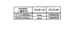
- the blog access DB of the service providing server generates an identifier (RANDID) that uniquely identifies access from the web terminal when the blog site provides the blog to the web terminal via the service providing server.
- the service providing server stores information on the blog parts advertised on the blog (store ID), the generated RANDID, and the URI in association with each other. In other words, the service providing server can identify the state of the blog site that is updated daily by which the Web terminal is accessed by RANDID.
- the service providing server acquires the SIP-URI corresponding to the selected blog part, and receives the SIP proxy via the Web terminal.
- the server is notified (see (5) to (7) in FIG. 11).
- the service providing server transmits the acquired corresponding SIP-URI (031234567@ntt.co.jp) to the SIP proxy server by redirection via the Web terminal.
- the SIP proxy server specifies the home connection destination information of the Web terminal from the home information DB based on the identifier added by the Web terminal when the SIP-URI is notified ((8) in FIG. 11). reference).
- the SIP proxy server Based on the IP address “192.168.1.1”, which is an identifier added by the Web terminal when “031234567@ntt.co.jp” is notified, the SIP-URI “0422xx@example.co.jp” of the Web terminal Is identified from the home information DB.
- the SIP proxy server makes a call to the telephone device using the specified in-home connection destination information (see (9) in FIG. 11). Specifically, in the above example, the SIP proxy server uses SIP for the SIP-URI “0422xx@example.co.jp” (telephone device) specified based on the IP address “192.168.1.1”. Make a call. Thereafter, the SIP proxy server receives a response to the call such as on-hook from the call destination (telephone device).
- the SIP proxy server transmits the response to the store using the device information specified by the outside information DB (see (10) in FIG. 11). .
- the SIP proxy server receives a response from the originating store, it connects the originating telephone device and the originating external device (see (11) in FIG. 11). Specifically, in the above-described example, when a response is received from the calling store, the SIP proxy server establishes a connection between the calling telephone device and the calling store.
- the communication control system can make a phone call to the store where the blog part is posted as an advertisement even when the blog part advertised on the blog site is clicked. It is possible to make a call connection easily without using any software.
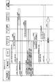
- FIG. 12 is a sequence diagram illustrating the flow of processing in the communication control system according to the third embodiment.
- the telephone device in the home network transmits a “REGISTER message” in SIP communication to the SIP proxy server via the HGW when the power is turned on (step S401).
- the SIP proxy server that has received this “REGISTER message” associates the IP address added to the “REGISTER message” by the HGW with the SIP-URI of the telephone device and stores it in the in-home information DB (step S402). Then, the SIP proxy server transmits a response “200 OK message” to the telephone device (step S403).
- the Web terminal accesses the blog provided by the blog site (step S404).
- the blog site that received the access transmits a store ID indicating a store advertised as a blog part to the service providing server by redirection via the Web terminal (steps S405 to S407).
- the service providing server when the service providing server receives the store ID from the blog site, the service providing server stores the device ID and an identifier for uniquely identifying the transmitted blog site in association with each other, and stores the blog received from the blog site in the Web terminal. Transmit (steps S408 and S409).
- the SIP-URI (031234567@ntt.co.jp) is acquired from the out-of-home information DB and redirected via the Web terminal to the SIP proxy server (steps S410 to S412).
- the same technique as that described in the second embodiment is used. be able to. Specifically, a method of transmitting directly from the service providing server to the SIP proxy server without going through the Web terminal, and a certificate such as SAML when notifying from the service providing server to the SIP proxy server through the Web terminal The technique used can be used. In addition, since the flow of processing when using each method is the same as that of the second embodiment, detailed description thereof is omitted here.
- the SIP proxy server transmits a message to the web terminal (step S413), and further, the in-home connection destination information “SIP-URI: corresponding to the IP address that is the identifier of the web terminal that has selected the store ID”. “0422xx@xxx.co.jp” is identified from the home information DB (step S414).
- the SIP proxy server uses the specified SIP-URI “0422xx@xxx.co.jp” to make a call to the telephone device (step S415).
- the SIP proxy server When the SIP proxy server receives a response from the telephone device that made the call (step S416), it sends the call to the store using the SIP-URI “03yyy@yyy.com” notified by the service providing server (step S416). S417).
- the SIP proxy server when receiving a response from the calling store (step S418), the SIP proxy server establishes a connection between the calling telephone device and the calling store, and counts the number of times the connection has been established (steps S419 to S418). Step S421).
- a log for charging a blogger or a store can be acquired.
- you can pay bloggers based on the total number of times (call connection, outgoing call, etc.), and affiliates on the web by phone A model can be formed.
- the service providing server counts the number of times a blog part (store ID) advertised on a blog is selected will be described with reference to FIGS. Specifically, when the service providing server receives the store ID from the blog site, the service providing server generates an identifier for uniquely identifying access to the blog in step S408 in FIG. 12, and associates the store with the generated identifier. Memorize ID and blog URI. The information stored here can be realized by acquiring various information in more detail from the blog received from the blog site when the information is stored in the blog access DB shown in FIG.
- the service providing server transmits “generated identifier“ RANDID ”,“ blogger ID indicating the blog site that transmitted the store ID (blog) ”, and store ID as illustrated in FIG. “11111e39564yu, aaaa, / 20080508” and the like are acquired and stored as “blog URI” for identifying the state of the blog.
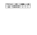
- the service providing server as shown in FIG.
- the service providing server that collects such information can pay the blogger a reward corresponding to the “PV number” by counting the “PV number” shown in FIG.
- FIG. 13 is a diagram illustrating an example of storing a blog accessed to the Web terminal
- FIG. 14 is a diagram illustrating an example of storing the number of times the blog accessed to the Web terminal is PVd.
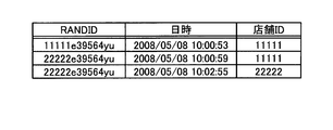
- the service providing server as shown in FIG. 15, “RANDID indicating the blog to which the selected blog part is advertised”, the selected “date and time”, and “ SIP-URI "" is acquired as a log. Then, the service providing server totals the “blogger ID” shown in FIG. 13 and the “date and time” and “store ID” shown in FIG. 15 corresponding to “RANDID” in FIG. By doing so, the service providing server, as shown in FIG. 16, “A blog site that identifies a blog site that advertises a blog part of a store selected by a Web terminal,” and a blog site to which the blogger ID is assigned.
- FIG. 15 is a diagram illustrating an example in which the store clicked on the blog and the date and time are tabulated.
- FIG. 16 is a diagram illustrating an example in which the number of times a blog part is actually selected on the Web terminal is tabulated for each blog.
- the service providing server counts the “store ID” in FIG. 15 for each “date and time” shown in FIG. By doing so, the service providing server, as shown in FIG. 17, “store ID indicating the clicked store”, “date and time” indicating the state of the blog site when the store is clicked, and the store ID For example, “11111, 2008/01/08, 2” can be counted as “click count” indicating the number of times (blog part) was clicked on the Web terminal. As a result, the service providing server can count the number of clicks for each store.
- FIG. 17 is a diagram illustrating an example in which the number of times actually selected for each store is tabulated.
- the service providing server totals the “store ID” in FIG. 15 for each “RANDID” corresponding to the “blogger ID” shown in FIG.
- the service providing server as shown in FIG. 18, “a“ blogger ID that identifies a blog site that advertises a blog part of a store selected by a Web terminal ”, a“ period ”that indicates a period of aggregation, Count “aaaa, 2008/05, 11111, 4” as “Store ID” indicating the clicked store and “Click count” indicating the number of times the store ID (blog part) has been clicked on the Web terminal. Can do.
- the service providing server can add up the stores and the number of times actually selected within a predetermined period for each blog.
- FIG. 18 is a diagram illustrating an example in which the stores actually selected and the number of times are counted for each blog within a predetermined period.
- the SIP proxy server counts the number of calls made to the store selected by the Web terminal and the number of calls made to the telephone device. Specifically, the SIP proxy server actually made a call for each blog, made a call for each store, made a call for each telephone device, and made a call for each blog within a predetermined period. You can count stores and times.
- the SIP proxy server performs “RANDID” generated to identify access to the blog, “Date” indicating the date and time when the RANDID is generated, service shown in FIG. “From” indicating the destination telephone number received from the providing server, and “TO” indicating the destination telephone number specified by the own device “11111e39564yu, 2008/01/08 10:00:53, 031234567 @ ntt .co.jp, 0422xx@example.co.jp "etc. are acquired and stored.
- FIG. 19 is a diagram illustrating an example of storing a transmission destination and a destination.
- the SIP proxy server that stores such information, for example, counts “From” in association with “RANDID” and “date and time” shown in FIG. 19, and displays “RANDID” in “Blogger ID” shown in FIG. To "”.
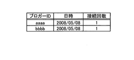
- the SIP proxy server as shown in FIG. 20, “a“ blogger ID ”that identifies a blog site on which a blog part of the store that sent the message is posted,“ date and time ”that indicates the date and time of transmission, and the number of times of transmission “Aaaa, 2008/01/08, 1” and the like can be tabulated as “number of times of transmission” indicating “.
- the SIP proxy server can count the number of transmissions for each blog.
- FIG. 20 is a diagram illustrating an example in which the number of transmissions for each blog is tabulated.
- the SIP proxy server counts “From” in association with “RANDID” and “date and time” shown in FIG. 19, converts the “RANDID” into “store ID” shown in FIG. .
- the SIP proxy server displays “store ID that identifies the store that made the transmission,“ date and time ”that indicates the date and time of transmission, and“ number of times of transmission ”that indicates the number of times of transmission. 11111, 2008/05/08, 2 "and so on.
- the SIP proxy server can count the number of transmissions for each store.
- FIG. 21 is a diagram illustrating an example in which the number of transmissions for each store is tabulated.
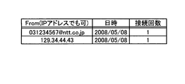
- the SIP proxy server performs aggregation in association with “From” and “Date” shown in FIG. By doing so, the SIP proxy server, as shown in FIG. 22, “From” indicating the telephone number of the telephone device of the calling home device, “Date” indicating the date and time of transmission, and “Number of times of transmission” “031234567@ntt.co.jp, May 08, 2008,” etc. can be counted as “number of outgoing calls”. As a result, the SIP proxy server can count the number of outgoing calls for each telephone device.
- FIG. 22 is a figure which shows the example which totaled the frequency
- the SIP proxy server identifies “Blogger ID” corresponding to “RANDID” shown in FIG. 19 from FIG. 13, and converts “RANDID” to “Blogger ID”. Further, the SIP proxy server identifies a store ID that matches the correspondence between “From” and “RANDID” shown in FIG. 19 from FIG. 15, and converts “From” in FIG. 19 into “store ID”. Then, the SIP proxy server totals “From” (store ID in FIG. 15) for each “date and time” in FIG. By doing so, the SIP proxy server, as shown in FIG.
- FIG. 23 is a diagram illustrating an example in which the number of transmissions within a predetermined period for each blog is tabulated.
- the SIP proxy server counts the number of times that the store and the telephone device are actually established will be described with reference to FIGS. 19 and 24 to 27. Specifically, the SIP proxy server actually connected for each blog, actually connected for each store, actually connected for each telephone device, and actually connected for each blog within a predetermined period. You can count stores and times.
- the SIP proxy server counts “From” in association with “RANDID” and “date and time” shown in FIG. 19, and converts the “RANDID” into “blogger ID” shown in FIG. .
- the SIP proxy server as shown in FIG. 24, “the blogger ID that identifies the blog site that advertised the blog part of the store where the call connection was actually established, the date and time when the connection was established, “Aaaa, 2008/01/08, 1” or the like can be counted as “date and time” and “number of connections” indicating the number of connection establishments.
- the SIP proxy server can count the number of times a call connection has been established for each blog.
- FIG. 24 is a diagram illustrating an example in which the number of times of actual connection for each blog is tabulated.
- the SIP proxy server counts “From” in association with “RANDID” and “date and time” shown in FIG. 19, and identifies and stores “Store ID” corresponding to “RANDID” from FIG. .
- the SIP proxy server as shown in FIG. 25, “the store ID that identifies the store where the call connection is actually established, the“ date and time ”that indicates the date and time when the connection is established, “11111, 2008/01/08, 1” or the like can be counted as the “number of connections” shown.
- the SIP proxy server can count the number of times that the call connection is established for each store.
- FIG. 25 is a diagram illustrating an example in which the number of times of actual connection for each store is tabulated.
- the SIP proxy server performs aggregation in association with “From” where “TO” shown in FIG. By doing so, the SIP proxy server, as shown in FIG. 26, “established“ From ”indicating the telephone number of the telephone device that actually established the call connection,“ date and time ”indicating the date and time when the connection was established, and established the connection. “031234567@ntt.co.jp, 2008/05/08, 1” can be counted as the “number of connections” indicating the number of times. As a result, the SIP proxy server can count the number of times of actual connection for each destination telephone number.
- FIG. 26 is a diagram illustrating an example in which the number of times of actual connection for each call destination telephone number is tabulated.
- the SIP proxy server identifies “Blogger ID” corresponding to “RANDID” shown in FIG. 19 from FIG. 13, and converts “RANDID” to “Blogger ID”. Further, the SIP proxy server identifies from FIG. 15 a store ID that matches the correspondence between “From” and “RANDID” shown in FIG. 19 where “TO” shown in FIG. 19 exists, and “From” in FIG. Is converted to “store ID”. Then, the SIP proxy server totals “From” (store ID in FIG. 15) for each “date and time” in FIG. By doing so, as shown in FIG. 27, the SIP proxy server “shows the telephone number of the telephone device that has actually established the call connection” and the blog that advertised the blog part of the store that has actually established the call connection.
- FIG. 27 is a diagram illustrating an example in which the number of stores actually connected and the number of times are counted for each blog within a predetermined period.
- RANDID as an identifier, it is possible to accurately grasp when and where a blog part is displayed, and whether each phase such as click, outgoing call, incoming call, etc. has been performed correctly.
- the blog site when an access request is received from a home device, the blog site transmits a blog to the home device by redirection through the service providing server, and the service providing server device A device ID that uniquely identifies a store and a SIP-URI indicating information for connecting to the store are stored in association with each other, and when the device ID provided to the blog is selected by the Web terminal, the selection is performed.
- the SIP-URI corresponding to the device ID obtained is acquired, and the acquired SIP-URI is notified to the SIP proxy server by redirection via the Web terminal.
- the SIP proxy server stores an identifier for uniquely identifying the Web terminal and an SIP-URI indicating information for connecting to the IP communication device in association with each other, and the SIP-URI of the store is serviced via the Web terminal.
- the SIP-URI of the telephone device is specified based on the IP address added by the Web terminal when the SIP-URI of the store is notified, and the SIP of the specified telephone device is specified.
- the call is sent to the store using the SIP-URI of the store and a response is sent from the sent store. If received, the connection between the telephone device and the store is established. For this reason, for example, in an external device (store) that provides blog parts to a blog site, it is possible to grasp which blog has been called by the user who has called the phone. It is possible to attract and solicit.
- the service providing server counts the number of times the blog is transmitted to the Web terminal, so that it is possible to acquire the blog browsing status and the like. For example, when a service system to which the present invention is applied is used, the usage fee of the system is changed for a blog site that provides a blog, or the blog layout (design) for soliciting customers depending on the blog viewing status It is possible to make use of it for changes to the solicitation method and so on.
- the service providing server since the service providing server counts the number of times the store ID is selected by the Web terminal, it is possible to acquire the blog parts access status and the like.
- a service system to which the present invention is applied when a service system to which the present invention is applied is used, it can be used for changing the layout (design) and solicitation method of blog parts for soliciting customers, and the access ranking of blog parts (stores). As a result, it is possible to use for soliciting customers and responding to customer needs.
- the SIP proxy server counts the number of calls made to the telephone device using the specified in-home connection destination information (SIP-URI).
- SIP-URI specified in-home connection destination information
- the SIP proxy server counts the number of times that the connection between the telephone device and the store is established when the response is received from the store from which the call is transmitted.
- the present invention is applied.
- the service system it is possible to collect not only the access status of blogs and blog parts (stores) but also whether or not they are actually used.
- detailed information that can be used for customer solicitation such as the usage ranking of blog parts (stores), can be aggregated.
- a SAML or a certificate can be used in the same manner as in the second embodiment.
- the service providing server notifies the generated external connection destination information (SIP-URI) to the SIP proxy server
- the service providing server adds the SAML or certificate to the generated SIP-URI and notifies the SIP proxy server.
- the SIP-URI is notified on the condition that the notified SIP-URI is authenticated as valid information based on the SAML or certificate notified from the service providing server via the Web terminal.
- the SIP-URI of the telephone device is identified from the home information DB from the IP address added by the Web terminal.
- Service form For example, in the first and second embodiments, description has been made by taking an advertisement of a website as an example. In the third embodiment, a blog has been described as an example. However, the present invention is not limited to this. Using a commonly used Web browser, the present invention can be applied to various services that use an external device from a home network.
- the present invention is not limited to this, and when the store ID is clicked on the Web,
- the store information can also be displayed on a TV equipped with a Web browser.
- the web browser-equipped television and the store can be connected using a VPN, and security can be kept high. That is, the IP communication device used in the present invention is not limited to the telephone device described in the embodiments.
- all or a part of the processes described as being automatically performed is manually performed.
- all or part of the processing described as being performed manually can be automatically performed by a known method.
- information including processing procedures, control procedures, specific names, various data and parameters shown in the above-mentioned documents and drawings can be arbitrarily changed unless otherwise specified.
- each component of each illustrated apparatus is functionally conceptual and does not necessarily need to be physically configured as illustrated.
- the specific form of distribution / integration of each device is not limited to that shown in the figure, and all or a part thereof may be functionally or physically distributed or arbitrarily distributed in arbitrary units according to various loads or usage conditions. It can be configured by integrating (for example, integrating the first transmission unit and the second transmission unit, or installing an IP address registration processing part by the SIP proxy server outside).
- all or any part of each processing function performed in each device may be realized by a CPU and a program analyzed and executed by the CPU, or may be realized as hardware by wired logic.
- the communication control method described in the present embodiment can be realized by executing a program prepared in advance on a computer such as a personal computer or a workstation.
- This program can be distributed via a network such as the Internet.
- the program can also be executed by being recorded on a computer-readable recording medium such as a hard disk, a flexible disk (FD), a CD-ROM, an MO, and a DVD and being read from the recording medium by the computer.
- a computer-readable recording medium such as a hard disk, a flexible disk (FD), a CD-ROM, an MO, and a DVD and being read from the recording medium by the computer.
- the communication control system, the communication control method, the call control server device, and the call control program according to the present invention are provided between a home device that performs various communications, a telephone device that is connected to another telephone device, and another network. It is useful for connecting a telephone device in a home network composed of a data relay device that controls various communications and an external device installed outside the home network, especially using special software. It is suitable for making a call connection easily.
- Service Providing Server 11 Communication Control I / F Unit 12 Storage Unit 13 Outside Information DB DESCRIPTION OF SYMBOLS 20 Control part 21 Access response part 22 Outside-home information acquisition part 30 SIP proxy server 31 Communication control I / F part 32 Storage part 33 In-home information DB 40 control unit 41 home information specifying unit 42 first transmission unit 43 second transmission unit 44 connection unit
Landscapes
- Engineering & Computer Science (AREA)
- Signal Processing (AREA)
- Computer Networks & Wireless Communication (AREA)
- Business, Economics & Management (AREA)
- Multimedia (AREA)
- General Business, Economics & Management (AREA)
- Finance (AREA)
- Strategic Management (AREA)
- Development Economics (AREA)
- Accounting & Taxation (AREA)
- Economics (AREA)
- Game Theory and Decision Science (AREA)
- General Engineering & Computer Science (AREA)
- Entrepreneurship & Innovation (AREA)
- Marketing (AREA)
- Physics & Mathematics (AREA)
- General Physics & Mathematics (AREA)
- Theoretical Computer Science (AREA)
- Telephonic Communication Services (AREA)
- Data Exchanges In Wide-Area Networks (AREA)
Abstract
Description
最初に、本実施例で用いる主要な用語を説明する。本実施例で用いる「通信制御システム(請求の範囲に記載の「通信制御システム」の一例である)」は、Web端末と電話装置とHGW(Home Gateway)とから構成される宅内ネットワークと、検索サイトなどの各種Webサイトを提供するサービス提供サーバと、SIP通信による通信制御を行うSIPプロキシサーバと、サービス提供サーバに提供されるWebサイトに店舗の情報を掲載して顧客を勧誘する店舗(店舗の電話装置)とが相互にネットワークにより接続される。
次に、図1を用いて、実施例1に係る通信制御システムの概要および特徴を説明する。図1は、実施例1に係る通信制御システムの全体構成を示すシステム構成図である。この通信制御システムは、上記したように、Web端末と電話装置とHGWとから構成される宅内ネットワークと、サービス提供サーバと、SIPプロキシサーバと、店舗と相互にネットワークにより接続される。
次に、図2を用いて、図1に示した通信制御システムの構成を説明する。図2は、実施例1に係る通信制御システムの構成を示すブロック図である。なお、HGWとWeb端末と電話装置と店舗とは、一般的な装置と同様の構成を有するので、ここでは、本発明において特徴的な機能を有するサービス提供サーバとSIPプロキシサーバとについて説明する。
図2に示すように、サービス提供サーバ10は、通信制御I/F部11と、記憶部12と、制御部20とを有する。通信制御I/F部11は、ネットワークを介して接続される他の装置との間でやり取りする各種情報に関する通信を制御する。具体的に例を挙げれば、通信制御I/F部11は、宅内ネットワークのWeb端末からHGWを介してWebアクセスを受け付けたり、Web端末に対してHGWを介してWebサイトを送信したり、SIPプロキシサーバ30に対してSIP-URIを通知したりする。
図2に示すように、SIPプロキシサーバ30は、通信制御I/F部31と、記憶部32と、制御部40とを有する。通信制御I/F部31は、ネットワークを介して接続される他の装置との間でやり取りする各種情報に関する通信を制御する。具体的に例を挙げれば、通信制御I/F部31は、サービス提供サーバ10からSIP-URIやIPアドレスを受け付けたり、宅内ネットワークの電話装置や店舗とSIPによる通信を制御したりする。
次に、図5を用いて、通信制御システムによる処理の流れを説明する。図5は、実施例1に係る通信制御システムによる処理の流れを示したシーケンス図である。
このように、実施例1によれば、Web端末を一意に識別するIPアドレスと電話装置と接続するための情報を示すSIP-URIとを対応付けて記憶し、店舗を一意に識別する店舗IDと店舗に関する装置情報とを対応付けて記憶し、Web端末からアクセス要求を受け付けた場合に、店舗IDを含む広告が表示されるWebサイトをWeb端末に送信し、送信された店舗IDがWeb端末により選択された場合に、当該選択された店舗IDに対応する装置情報を取得して、店舗と接続するためのSIP-URIを選択し、同様に、送信された店舗IDがWeb端末により選択された場合に、当該店舗IDを選択したWeb端末のIPアドレスに対応するSIP-URIを特定し、特定されたSIP-URIを用いて、電話装置に対して発信し、発信された電話装置から応答を受信した場合に、生成されたSIP-URIを用いて、店舗に対して発信し、発信された店舗から応答を受信した場合に、電話装置と店舗との接続を確立するので、ユーザが一般的なWebブラウザを用いてアクセスしたWebサイトに表示される広告(宅外情報)をクリックするだけで、当該広告を掲載した店舗に電話発信することができる結果、特殊なソフトウエアを用いることなく、容易に通話接続することが可能である。
まず、図7を用いて、サービス提供サーバからWeb端末を介することなく、SIPプロキシサーバに直接通知する場合について説明する。図7は、サービス提供サーバからSIPプロキシサーバに装置情報を直接送信する処理の流れを示すシーケンス図である。なお、この例では、サービス提供サーバとSIPプロキシサーバとは互いに信頼のおける装置であると認識している。
次に、図8を用いて、サービス提供サーバからSIPプロキシサーバへWeb端末を介して送信する際に、SAMLなどの証明書を用いて送信する場合について説明する。図8は、サービス提供サーバからSIPプロキシサーバへWeb端末を介して送信する際に、SAMLを用いて通知する処理の流れを示すシーケンス図である。
まず、図11を用いて、実施例3に係る通信制御システムの全体構成について説明する。図11は、実施例3に係る通信制御システムの全体構成を示す図である。
次に、図12を用いて、実施例3に係る通信制御システムにおける処理の流れについて説明する。図12は、実施例3に係る通信制御システムにおける処理の流れを示すシーケンス図である。
また、実施例3では、ブロガーや店舗に対して課金するためのログなどを取得することができる。つまり、どのブログを閲覧したユーザが電話してきたかを把握することができる結果、集計した回数(通話接続,発信など)に基づき、ブロガーに対して報酬を支払うことができ、電話によるWeb上のアフェリエイトモデルを形成できる。
まず、図13~図18を用いて、サービス提供サーバが、ブログに広告されるブログパーツ(店舗ID)が選択された回数を計数する場合について説明する。具体的には、サービス提供サーバは、ブログサイトから店舗IDを受信した場合に、図12のステップS408において、ブログへのアクセスを一意に識別する識別子を生成し、生成した識別子に対応付けて店舗IDやブログURIなどを記憶する。ここで記憶される情報は、図11で示したブログアクセスDBに情報を格納する際に、ブログサイトから受信したブログから各種情報をより詳細に取得することで実現できる。
次に、図19~図23を用いて、SIPプロキシサーバが、Web端末により選択された店舗に発信した回数や電話装置に発信した回数を計数する場合について説明する。具体的には、SIPプロキシサーバは、ブログごとに実際に発信した回数、店舗ごとに実際に発信した回数、電話装置ごとに実際に発信した回数、ブログごとに所定の期間内で実際に発信した店舗と回数を計数することができる。
次に、図19と図24~図27を用いてSIPプロキシサーバが、店舗と電話装置とを実際に接続確立した回数を計数する場合について説明する。具体的には、SIPプロキシサーバは、ブログごとに実際に接続した回数、店舗ごとに実際に接続した回数、電話装置ごとに実際に接続した回数、ブログごとに所定の期間内で実際に接続した店舗と回数を計数することができる。
このように、実施例3によれば、ブログサイトは、宅内装置からアクセス要求を受け付けた場合に、前記サービス提供サーバを介したリダイレクトで、ブログを前記宅内装置に送信し、サービス提供サーバ装置は、店舗を一意に識別する装置IDと当該店舗と接続するための情報を示すSIP-URIとを対応付けて記憶し、ブログに提供される装置IDがWeb端末により選択された場合に、当該選択された装置IDに対応するSIP-URIを取得して、Web端末を介したリダイレクトで、取得したSIP-URIをSIPプロキシサーバに通知する。そして、SIPプロキシサーバは、Web端末を一意に識別する識別子とIP通信機と接続するための情報を示すSIP-URIとを対応付けて記憶し、店舗のSIP-URIがWeb端末を介してサービス提供サーバから通知された場合に、当該店舗のSIP-URIが通知される際にWeb端末により付加されたIPアドレスに基づいて、電話装置のSIP-URIを特定し、特定された電話装置のSIP-URIを用いて、電話装置に対して発信するとともに、発信され電話装置から応答を受信した場合に、店舗のSIP-URIを用いて、店舗に対して発信し、発信された店舗から応答を受信した場合に、電話装置と店舗との接続を確立する。そのため、例えば、ブログサイトにブログパーツを提供する宅外装置(店舗)では、どのブログを閲覧したユーザが電話してきたかを把握することができる結果、顧客の囲い込みなど、顧客に対して効果的な誘致および勧誘を行うことが可能である。
例えば、実施例1と2では、Webサイトの広告を例にして説明し、実施例3では、ブログを例にして説明したが、本発明はこれに限定されるものではなく、一般的に利用されているWebブラウザを用いて、宅外装置を宅内ネットワークから利用する様々なサービスに適用することができる。
例えば、上記した実施例では、サービス提供サーバとSIPプロキシサーバとを別の鏡体で実現している例について説明したが、本発明はこれに限定されるものではなく、サービス提供サーバとSIPプロキシサーバとを同じ筺体で実現することもできる。
なお、本実施例で説明した通信制御方法は、あらかじめ用意されたプログラムをパーソナルコンピュータやワークステーションなどのコンピュータで実行することによって実現することができる。このプログラムは、インターネットなどのネットワークを介して配布することができる。また、このプログラムは、ハードディスク、フレキシブルディスク(FD)、CD-ROM、MO、DVDなどのコンピュータで読み取り可能な記録媒体に記録され、コンピュータによって記録媒体から読み出されることによって実行することもできる。
11 通信制御I/F部
12 記憶部
13 宅外情報DB
20 制御部
21 アクセス応答部
22 宅外情報取得部
30 SIPプロキシサーバ
31 通信制御I/F部
32 記憶部
33 宅内情報DB
40 制御部
41 宅内情報特定部
42 第一発信部
43 第二発信部
44 接続部
Claims (15)
- 各種通信を行う宅内装置とIP通信機とから構成される宅内ネットワークにおける前記IP通信機と、前記宅内ネットワークの外に設置されている宅外装置とを接続する通信制御システムであって、
前記宅内装置を一意に識別する識別子と前記IP通信機と接続するための情報を示す宅内接続先情報とを対応付けて記憶する宅内情報記憶手段と、
前記宅外装置を一意に識別する装置IDと当該宅外装置と接続するための情報を示す宅外接続先情報とを対応付けて記憶する宅外情報記憶手段と、
前記宅内装置からアクセス要求を受け付けた場合に、前記宅外情報記憶手段に記憶される装置IDを前記宅内装置に送信するアクセス応答手段と、
前記アクセス応答手段により送信された装置IDが前記宅内装置により選択されたことが通知された場合に、当該通知された装置IDに対応する宅外接続先情報を前記宅外情報記憶手段から取得する宅外情報取得手段と、
前記アクセス応答手段により送信された装置IDが前記宅内装置により選択されたことが通知された場合に、当該選択した宅内装置の識別子に対応付けて前記宅内情報記憶手段に記憶される宅内接続先情報を特定する宅内情報特定手段と、
前記宅内情報特定手段により特定された宅内接続先情報を用いて、前記IP通信機に対して発信する第一の発信手段と、
前記第一の発信手段により発信されたIP通信機から応答を受信した場合に、前記宅外情報取得手段により取得された宅外接続先情報を用いて、前記宅外装置に対して発信する第二の発信手段と、
前記第二の発信手段により発信された宅外装置から応答を受信した場合に、前記第一の発信手段により発信されたIP通信機と前記第二の発信手段により発信された宅外装置との接続を確立する接続確立手段と、
を備えたことを特徴とする通信制御システム。 - 各種通信を行う宅内装置とIP通信機と構成される宅内ネットワークと、前記宅内装置に対して各種サービスを提供するサービス提供サーバ装置と、前記宅内ネットワークの外に設置されている宅外装置と、前記IP通信機と宅外装置とを接続する呼制御サーバ装置とから構成される通信制御システムであって、
前記サービス提供サーバ装置は、
前記宅外装置を一意に識別する装置IDと当該宅外装置と接続するための情報を示す装宅外接続先情報とを対応付けて記憶する宅外情報記憶手段と、
前記宅内装置からアクセス要求を受け付けた場合に、前記宅外情報記憶手段に記憶される装置IDを前記宅内装置に送信するアクセス応答手段と、
前記アクセス応答手段により送信された装置IDが前記宅内装置により選択されたことが通知された場合に、当該通知された装置IDに対応する宅外接続先情報を前記宅外情報記憶手段から取得し、前記宅内装置を介したリダイレクトで、取得した宅外接続先情報を呼制御サーバ装置に通知する宅外情報取得手段と、を備え、
呼制御サーバ装置は、
前記宅内装置を一意に識別する識別子と前記IP通信機と接続するための情報を示す宅内接続先情報とを対応付けて記憶する宅内情報記憶手段と、
前記サービス提供サーバ装置の宅外情報取得手段により宅外接続先情報が宅内装置を介して通知された場合に、当該宅外接続先情報が通知される際に宅内装置により付加された宅内装置の識別子に基づいて、前記宅内接続先情報を前記宅内情報記憶手段から特定する宅内情報特定手段と、
前記宅内情報特定手段により特定された宅内接続先情報を用いて、前記IP通信機に対して発信する第一の発信手段と、
前記第一の発信手段により発信されたIP通信機から応答を受信した場合に、前記宅外情報取得手段により取得された宅外接続先情報を用いて、前記宅外装置に対して発信する第二の発信手段と、
前記第二の発信手段により発信された宅外装置から応答を受信した場合に、前記第一の発信手段により発信されたIP通信機と前記第二の発信手段により発信された宅外装置との接続を確立する接続確立手段と、
を備えたことを特徴とする通信制御システム。 - 前記サービス提供サーバ装置の宅外情報取得手段は、前記取得した宅外接続先情報を前記呼制御サーバ装置に通知するのに際して、当該宅外接続先情報に検証可能な形式を付加して通知し、
前記呼制御サーバ装置の宅内情報特定手段は、前記サービス提供サーバ装置から宅内装置を介して通知された検証可能な形式に基づいて、前記通知された宅外接続先情報が正当な情報であると認証されることを条件として、当該宅外接続先情報が通知される際に宅内装置により付加された宅内装置の識別子から、当該宅内装置の宅内接続先情報を前記宅内情報記憶手段から特定することを特徴とする請求項2に記載の通信制御システム。 - 前記サービス提供サーバ装置のアクセス応答手段は、前記宅内装置によるアクセス要求を受け付けた場合に、前記宅外接続先情報を生成して宅外情報記憶手段に格納するとともに、前記宅外情報記憶手段に記憶される宅外接続先情報を宅内装置に送信することを特徴とする請求項1~3のいずれか一つに記載の通信制御システム。
- 各種通信を行う宅内装置とIP通信機と構成される宅内ネットワークと、前記宅内装置に対してコンテンツを提供するWebサーバ装置と、前記コンテンツを顧客に対して勧誘するためのコンテンツ情報を宅内装置に提供するサービス提供サーバ装置と、前記Webサーバ装置に提供されるコンテンツにコンテンツ情報を掲載する宅外装置と、前記IP通信機と宅外装置とを接続する呼制御サーバ装置とから構成される通信制御システムであって、
前記Webサーバ装置は、
前記宅内装置からアクセス要求を受け付けた場合に、前記サービス提供サーバを介したリダイレクトで、前記コンテンツを前記宅内装置に送信するアクセス応答手段と、
前記サービス提供サーバ装置は、
前記宅外装置を一意に識別する装置IDと当該宅外装置と接続するための情報を示す装宅外接続先情報とを対応付けて記憶する宅外情報記憶手段と、
前記コンテンツによりWeb端末に提供される装置IDが前記宅内装置により選択された場合に、当該選択された装置IDに対応する宅外接続先情報を前記宅外情報記憶手段から取得して、前記宅内装置を介したリダイレクトで、前記取得した宅外接続先情報を呼制御サーバ装置に通知する宅外情報送信手段と、
前記呼制御サーバ装置は、
前記宅内装置を一意に識別する識別子と前記IP通信機と接続するための情報を示す宅内接続先情報とを対応付けて記憶する宅内情報記憶手段と、
前記宅外接続先情報が宅内装置を介して前記サービス提供サーバ装置から通知された場合に、当該宅外接続先情報が通知される際に宅内装置により付加された宅内装置の識別子に基づいて、前記宅内接続先情報を前記宅内情報記憶手段から特定する宅内情報特定手段と、
前記宅内情報特定手段により特定された宅内接続先情報を用いて、前記IP通信機に対して発信する第一の発信手段と、
前記第一の発信手段により発信されたIP通信機から応答を受信した場合に、前記サービス提供サーバ装置から通知された宅外接続先情報を用いて、前記宅外装置に対して発信する第二の発信手段と、
前記第二の発信手段により発信された宅外装置から応答を受信した場合に、前記第一の発信手段により発信されたIP通信機と前記第二の発信手段により発信された宅外装置との接続を確立する接続確立手段と、
を備えたことを特徴とする通信制御システム。 - 前記サービス提供サーバ装置の宅外情報送信手段は、前記取得した宅外接続先情報を前記呼制御サーバ装置に通知するのに際して、前記宅外接続先情報に検証可能な形式を付加して通知し、
前記呼制御サーバ装置の宅内情報特定手段は、前記サービス提供サーバ装置から宅内装置を介して通知された検証可能な形式に基づいて、前記通知された宅外接続先情報が正当な情報であると認証されることを条件として、当該宅外接続先情報が通知される際に宅内装置により付加された識別子から、前記宅内接続先情報を前記宅内情報記憶手段から特定することを特徴とする請求項5に記載の通信制御システム。 - 前記サービス提供サーバ装置は、前記Webサーバ装置のアクセス応答手段からコンテンツが自装置に送信された回数を計数する計数手段をさらに備えたことを特徴とする請求項5または6に記載の通信制御システム。
- 前記計数手段は、前記コンテンツに提供される装置IDが前記宅内装置により選択された場合に、当該選択された回数を計数することを特徴とする請求項7に記載の通信制御システム。
- 前記呼制御サーバ装置は、前記第一の発信手段により前記宅内情報特定手段により特定された宅内接続先情報を用いて、前記IP通信機に対して発信された回数を計数する発信回数計数手段をさらに備えたことを特徴とする請求項5~8のいずれか一つに記載の通信制御システム。
- 前記呼制御サーバ装置は、前記接続確立手段により前記第二の発信手段により発信された宅外装置から応答を受信した場合に、前記第一の発信手段により発信されたIP通信機と前記第二の発信手段により発信された宅外装置との接続が確立された回数を計数する接続回数計数手段をさらに備えたことを特徴とする請求項5~9のいずれか一つに記載の通信制御システム。
- 各種通信を行う宅内装置とIP通信機とから構成される宅内ネットワークにおける前記IP通信機と、前記宅内ネットワークの外に設置されている宅外装置とを接続する通信制御システムに適用する通信制御方法であって、
前記宅内装置からアクセス要求を受け付けた場合に、前記宅外装置を一意に識別する装置IDと当該宅外装置と接続するための情報を示す装宅外接続先情報とを対応付けて記憶する宅外情報記憶部に記憶される装置IDを前記宅内装置に送信するアクセス応答工程と、
前記アクセス応答手段により送信された装置IDが前記宅内装置により選択されたことが通知された場合に、当該通知された装置IDに対応する宅外接続先情報を前記宅外情報記憶手段から取得する宅外情報取得工程と、
前記アクセス応答手段により送信された装置IDが前記宅内装置により選択されたことが通知された場合に、当該選択した宅内装置の識別子に対応付けて前記宅内情報記憶手段に記憶される宅内接続先情報を特定する宅内情報特定工程と、
前記宅内情報特定工程により特定された宅内接続先情報を用いて、前記IP通信機に対して発信する第一の発信工程と、
前記第一の発信工程により発信されたIP通信機から応答を受信した場合に、前記宅外情報取得手段により取得された宅外接続先情報を用いて、前記宅外装置に対して発信する第二の発信工程と、
前記第二の発信工程により発信された宅外装置から応答を受信した場合に、前記第一の発信工程により発信されたIP通信機と前記第二の発信工程により発信された宅外装置との接続を確立する接続確立工程と、
を含んだことを特徴とする通信制御方法。 - 各種通信を行う宅内装置とIP通信機と構成される宅内ネットワークと、前記宅内装置に対して各種サービスを提供するサービス提供サーバ装置と、前記宅内ネットワークの外に設置されている宅外装置と、前記IP通信機と宅外装置とを接続する呼制御サーバ装置とから構成される通信制御システムにおける前記呼制御サーバ装置であって、
前記宅内装置を一意に識別する識別子と前記IP通信機と接続するための情報を示す宅内接続先情報とを対応付けて記憶する宅内情報記憶手段と、
前記サービス提供サーバ装置により宅外接続先情報が宅内装置を介して通知された場合に、当該宅外接続先情報が通知される際に宅内装置により付加された宅内装置の識別子に基づいて、前記宅内接続先情報を前記宅内情報記憶手段から特定する宅内情報特定手段と、
前記宅内情報特定手段により特定された宅内接続先情報を用いて、前記IP通信機に対して発信する第一の発信手段と、
前記第一の発信手段により発信されたIP通信機から応答を受信した場合に、前記宅外情報取得手段により取得された宅外接続先情報を用いて、前記宅外装置に対して発信する第二の発信手段と、
前記第二の発信手段により発信された宅外装置から応答を受信した場合に、前記第一の発信手段により発信されたIP通信機と前記第二の発信手段により発信された宅外装置との接続を確立する接続確立手段と、
を備えたことを特徴とする呼制御サーバ装置。 - 各種通信を行う宅内装置とIP通信機と構成される宅内ネットワークと、前記宅内装置に対してコンテンツを提供するWebサーバ装置と、前記コンテンツを顧客に対して勧誘するためのコンテンツ情報を宅内装置に提供するサービス提供サーバ装置と、前記Webサーバ装置に提供されるコンテンツにコンテンツ情報を掲載する宅外装置と、前記IP通信機と宅外装置とを接続する呼制御サーバ装置とから構成される通信制御システムにおける前記呼制御サーバ装置であって、
前記宅内装置を一意に識別する識別子と前記IP通信機と接続するための情報を示す宅内接続先情報とを対応付けて記憶する宅内情報記憶手段と、
前記宅外接続先情報が宅内装置を介して前記サービス提供サーバ装置から通知された場合に、当該宅外接続先情報が通知される際に宅内装置により付加された宅内装置の識別子に基づいて、前記宅内接続先情報を前記宅内情報記憶手段から特定する宅内情報特定手段と、
前記宅内情報特定手段により特定された宅内接続先情報を用いて、前記IP通信機に対して発信する第一の発信手段と、
前記第一の発信手段により発信されたIP通信機から応答を受信した場合に、前記サービス提供サーバ装置から通知された宅外接続先情報を用いて、前記宅外装置に対して発信する第二の発信手段と、
前記第二の発信手段により発信された宅外装置から応答を受信した場合に、前記第一の発信手段により発信されたIP通信機と前記第二の発信手段により発信された宅外装置との接続を確立する接続確立手段と、
を備えたことを特徴とする呼制御サーバ装置。 - 各種通信を行う宅内装置とIP通信機と構成される宅内ネットワークと、前記宅内装置に対して各種サービスを提供するサービス提供サーバ装置と、前記宅内ネットワークの外に設置されている宅外装置と、前記IP通信機と宅外装置とを接続する呼制御サーバ装置とから構成される通信制御システムにおける前記呼制御サーバ装置としてのコンピュータに実行する呼制御プログラムであって、
前記サービス提供サーバ装置により宅外接続先情報が宅内装置を介して通知された場合に、当該宅外接続先情報が通知される際に宅内装置により付加された宅内装置の識別子に基づいて、前記宅内装置を一意に識別する識別子と前記IP通信機と接続するための情報を示す宅内接続先情報とを対応付けて記憶する宅内情報記憶部から前記宅内接続先情報を特定する宅内情報特定手順と、
前記宅内情報特定手順により特定された宅内接続先情報を用いて、前記IP通信機に対して発信する第一の発信手順と、
前記第一の発信手順により発信されたIP通信機から応答を受信した場合に、前記宅外情報取得手順により取得された宅外接続先情報を用いて、前記宅外装置に対して発信する第二の発信手順と、
前記第二の発信手順により発信された宅外装置から応答を受信した場合に、前記第一の発信手順により発信されたIP通信機と前記第二の発信手順により発信された宅外装置との接続を確立する接続確立手順と、
をコンピュータに実行させることを特徴とする呼制御プログラム。 - 各種通信を行う宅内装置とIP通信機と構成される宅内ネットワークと、前記宅内装置に対してコンテンツを提供するWebサーバ装置と、前記コンテンツを顧客に対して勧誘するためのコンテンツ情報を宅内装置に提供するサービス提供サーバ装置と、前記Webサーバ装置に提供されるコンテンツにコンテンツ情報を掲載する宅外装置と、前記IP通信機と宅外装置とを接続する呼制御サーバ装置とから構成される通信制御システムにおける前記呼制御サーバ装置としてのコンピュータに実行する呼制御プログラムであって、
前記宅外接続先情報が宅内装置を介して前記サービス提供サーバ装置から通知された場合に、当該宅外接続先情報が通知される際に宅内装置により付加された宅内装置の識別子に基づいて、前記宅内装置を一意に識別する識別子と前記IP通信機と接続するための情報を示す宅内接続先情報とを対応付けて記憶する宅内情報記憶部から前記宅内接続先情報を特定する宅内情報特定手順と、
前記宅内情報特定手段により特定された宅内接続先情報を用いて、前記IP通信機に対して発信する第一の発信手順と、
前記第一の発信手段により発信されたIP通信機から応答を受信した場合に、前記サービス提供サーバ装置から通知された宅外接続先情報を用いて、前記宅外装置に対して発信する第二の発信手順と、
前記第二の発信手順により発信された宅外装置から応答を受信した場合に、前記第一の発信手順により発信されたIP通信機と前記第二の発信手順により発信された宅外装置との接続を確立する接続確立手順と、
をコンピュータに実行させることを特徴とする呼制御プログラム。
Priority Applications (3)
| Application Number | Priority Date | Filing Date | Title |
|---|---|---|---|
| EP20090766620 EP2290935B1 (en) | 2008-06-16 | 2009-06-15 | Communication control system, communication control method, call control server device, and call control program |
| US12/996,807 US8700783B2 (en) | 2008-06-16 | 2009-06-15 | Communication control system, communication control method, call control server device, and call control program |
| CN200980121471.5A CN102057658B (zh) | 2008-06-16 | 2009-06-15 | 通信控制系统、通信控制方法、呼叫控制服务器装置 |
Applications Claiming Priority (2)
| Application Number | Priority Date | Filing Date | Title |
|---|---|---|---|
| JP2008-157184 | 2008-06-16 | ||
| JP2008157184A JP4624447B2 (ja) | 2008-06-16 | 2008-06-16 | 通信制御システム、通信制御方法、呼制御サーバ装置および呼制御プログラム |
Publications (1)
| Publication Number | Publication Date |
|---|---|
| WO2009154172A1 true WO2009154172A1 (ja) | 2009-12-23 |
Family
ID=41434088
Family Applications (1)
| Application Number | Title | Priority Date | Filing Date |
|---|---|---|---|
| PCT/JP2009/060882 Ceased WO2009154172A1 (ja) | 2008-06-16 | 2009-06-15 | 通信制御システム、通信制御方法、呼制御サーバ装置および呼制御プログラム |
Country Status (6)
| Country | Link |
|---|---|
| US (1) | US8700783B2 (ja) |
| EP (1) | EP2290935B1 (ja) |
| JP (1) | JP4624447B2 (ja) |
| KR (1) | KR101209577B1 (ja) |
| CN (1) | CN102057658B (ja) |
| WO (1) | WO2009154172A1 (ja) |
Families Citing this family (13)
| Publication number | Priority date | Publication date | Assignee | Title |
|---|---|---|---|---|
| US8374172B2 (en) * | 2009-04-03 | 2013-02-12 | At&T Intellectual Property I, L.P. | Method and apparatus for managing communication sessions |
| CN102143172B (zh) * | 2011-03-21 | 2014-10-29 | 杭州华三通信技术有限公司 | 一种视频数据的传输方法和设备 |
| KR101923487B1 (ko) * | 2011-09-29 | 2018-11-30 | 삼성전자 주식회사 | 통신 연결 서비스 제공 방법 및 장치 |
| JP5887507B2 (ja) * | 2011-11-28 | 2016-03-16 | パナソニックIpマネジメント株式会社 | 通信機器間の接続確立方法、通信機器、及びサーバ装置 |
| JP6074165B2 (ja) * | 2012-06-01 | 2017-02-01 | キヤノン株式会社 | 情報処理装置、情報処理方法およびプログラム |
| JP6364824B2 (ja) * | 2014-03-06 | 2018-08-01 | 富士通株式会社 | 発呼制御方法、情報処理装置、発呼制御プログラム、発呼制御システム |
| US10075494B2 (en) | 2015-05-08 | 2018-09-11 | Avaya Inc. | Pushing graphical user interface widgets for communication devices |
| US20160328128A1 (en) * | 2015-05-08 | 2016-11-10 | Avaya Inc. | Pulling graphical user interface widgets for communication devices |
| US9667785B2 (en) * | 2015-05-26 | 2017-05-30 | Avaya Inc. | System and method for preserving call language settings for session initiation protocol diverted calls |
| US10021022B2 (en) * | 2015-06-30 | 2018-07-10 | Juniper Networks, Inc. | Public network address conservation |
| US20190386982A1 (en) * | 2016-08-12 | 2019-12-19 | Acrodea. Inc. | System and method for notification of occurrence of event |
| JP7381834B2 (ja) | 2019-03-15 | 2023-11-16 | アイコム株式会社 | 音声通信システムおよび呼制御サーバの冗長化方法 |
| US11456994B2 (en) * | 2019-03-18 | 2022-09-27 | Charter Communications Operating, Llc | Methods and apparatus for controlling and implementing firewalls |
Citations (7)
| Publication number | Priority date | Publication date | Assignee | Title |
|---|---|---|---|---|
| JPH10336349A (ja) | 1997-03-31 | 1998-12-18 | Nippon Telegr & Teleph Corp <Ntt> | 分散情報検索手段を用いた電話発信方法およびコンピュータ読み取り可能な記録媒体 |
| JP2001339518A (ja) * | 2000-05-30 | 2001-12-07 | Hidekazu Morita | 電話によるコンタクトシステム |
| JP2003022223A (ja) * | 2001-04-04 | 2003-01-24 | Alcatel | ボイスクッキーを使用するセッション開始プロトコルの経路指定 |
| JP2006108768A (ja) * | 2004-09-30 | 2006-04-20 | Oki Electric Ind Co Ltd | ユーザ端末の識別情報を隠蔽した通信接続方法及び通信システム |
| JP2006229964A (ja) * | 2005-02-17 | 2006-08-31 | Phil Hwan Yun | ユーザと事業体間のコール仲介サービス方法及びシステム |
| JP2007067544A (ja) * | 2005-08-29 | 2007-03-15 | Oki Electric Ind Co Ltd | 第三者呼制御機能を備えるWebサーバ |
| JP2008098786A (ja) * | 2006-10-06 | 2008-04-24 | Quantum Networks Inc | 第三者呼制御による二者間通話制御装置、その方法及び二者間通話制御プログラム |
Family Cites Families (6)
| Publication number | Priority date | Publication date | Assignee | Title |
|---|---|---|---|---|
| US9197599B1 (en) * | 1997-09-26 | 2015-11-24 | Verizon Patent And Licensing Inc. | Integrated business system for web based telecommunications management |
| US6826403B1 (en) * | 2000-09-12 | 2004-11-30 | Phonepages Of Sweden Ab | Method and system for identifying a user |
| JP4277621B2 (ja) * | 2003-08-20 | 2009-06-10 | 沖電気工業株式会社 | サービス提供システムおよびその方法ならびにサービス提供プログラムおよび記録媒体 |
| JP2005284743A (ja) | 2004-03-30 | 2005-10-13 | Sanyo Electric Co Ltd | バーチャル店舗システム |
| US20060050686A1 (en) * | 2004-09-08 | 2006-03-09 | Commoca, Inc. | Software platform for developing, delivering and managing data-voice applications operating on an internet protocol (IP) phone |
| WO2006126202A2 (en) * | 2005-05-26 | 2006-11-30 | Kayote Networks, Inc. | Detection of spit in voip calls |
-
2008
- 2008-06-16 JP JP2008157184A patent/JP4624447B2/ja not_active Expired - Fee Related
-
2009
- 2009-06-15 CN CN200980121471.5A patent/CN102057658B/zh not_active Expired - Fee Related
- 2009-06-15 US US12/996,807 patent/US8700783B2/en active Active
- 2009-06-15 KR KR1020107027087A patent/KR101209577B1/ko not_active Expired - Fee Related
- 2009-06-15 EP EP20090766620 patent/EP2290935B1/en not_active Not-in-force
- 2009-06-15 WO PCT/JP2009/060882 patent/WO2009154172A1/ja not_active Ceased
Patent Citations (7)
| Publication number | Priority date | Publication date | Assignee | Title |
|---|---|---|---|---|
| JPH10336349A (ja) | 1997-03-31 | 1998-12-18 | Nippon Telegr & Teleph Corp <Ntt> | 分散情報検索手段を用いた電話発信方法およびコンピュータ読み取り可能な記録媒体 |
| JP2001339518A (ja) * | 2000-05-30 | 2001-12-07 | Hidekazu Morita | 電話によるコンタクトシステム |
| JP2003022223A (ja) * | 2001-04-04 | 2003-01-24 | Alcatel | ボイスクッキーを使用するセッション開始プロトコルの経路指定 |
| JP2006108768A (ja) * | 2004-09-30 | 2006-04-20 | Oki Electric Ind Co Ltd | ユーザ端末の識別情報を隠蔽した通信接続方法及び通信システム |
| JP2006229964A (ja) * | 2005-02-17 | 2006-08-31 | Phil Hwan Yun | ユーザと事業体間のコール仲介サービス方法及びシステム |
| JP2007067544A (ja) * | 2005-08-29 | 2007-03-15 | Oki Electric Ind Co Ltd | 第三者呼制御機能を備えるWebサーバ |
| JP2008098786A (ja) * | 2006-10-06 | 2008-04-24 | Quantum Networks Inc | 第三者呼制御による二者間通話制御装置、その方法及び二者間通話制御プログラム |
Non-Patent Citations (1)
| Title |
|---|
| See also references of EP2290935A4 |
Also Published As
| Publication number | Publication date |
|---|---|
| CN102057658B (zh) | 2014-07-30 |
| CN102057658A (zh) | 2011-05-11 |
| JP2009303078A (ja) | 2009-12-24 |
| EP2290935B1 (en) | 2014-08-13 |
| JP4624447B2 (ja) | 2011-02-02 |
| EP2290935A4 (en) | 2013-01-16 |
| US8700783B2 (en) | 2014-04-15 |
| EP2290935A1 (en) | 2011-03-02 |
| US20110125910A1 (en) | 2011-05-26 |
| KR101209577B1 (ko) | 2012-12-07 |
| KR20100137588A (ko) | 2010-12-30 |
Similar Documents
| Publication | Publication Date | Title |
|---|---|---|
| JP4624447B2 (ja) | 通信制御システム、通信制御方法、呼制御サーバ装置および呼制御プログラム | |
| US20230057193A1 (en) | Multi-services application gateway and system employing the same | |
| US11183282B2 (en) | Multi-services application gateway and system employing the same | |
| US20220208319A1 (en) | Multi-services application gateway and system employing the same | |
| US20210218571A1 (en) | Multi-services application gateway and system employing the same | |
| US20180198692A1 (en) | Multi-services application gateway and system employing the same | |
| EP2722756B1 (en) | User terminal, operator server, remote support method and user terminal progam | |
| US9209984B2 (en) | Systems and methods to facilitate communications | |
| WO2004105333A1 (ja) | 安全な仮想プライベート・ネットワーク | |
| CN102377617A (zh) | 监视移动互联网活动的系统、方法和设备 | |
| US20120023247A1 (en) | Anonymous communication system, anonymous communication method, communication control apparatus, terminal apparatus and communication control program | |
| KR101024562B1 (ko) | 서비스 관리 장치 및 서비스 제공 시스템 | |
| JPWO2010044471A1 (ja) | サービス提供システムおよびサービス提供方法 | |
| JP4800332B2 (ja) | サービス提供システム、サービス提供方法およびサービス提供プログラム | |
| US8842683B2 (en) | Audio/video communication system | |
| JP5189551B2 (ja) | Webサービス制御システム及びWebサービス制御方法 | |
| JP5367477B2 (ja) | サービス提供システムおよびサービス提供方法 | |
| JP4345300B2 (ja) | 通信管理用サーバ及び通信管理用サーバ制御プログラム | |
| JP5687258B2 (ja) | リモートサポートサーバ、ユーザ端末、リモートサポートシステム、リモートサポート方法、及びリモートサポートシステム用プログラム | |
| JP4703597B2 (ja) | 呼制御システム、呼制御方法、呼接続要求処理装置、及びプログラム | |
| JP2011008712A (ja) | サービス提供システムおよびサービス提供方法 | |
| KR20180110576A (ko) | 전화 통화시 음성과 데이터를 결합한 시스템 및 그 방법 | |
| JP2014082640A (ja) | ユーザ端末、オペレータサーバ、オペレータシステム、リモートサポート方法、及びオペレータシステム用プログラム |
Legal Events
| Date | Code | Title | Description |
|---|---|---|---|
| WWE | Wipo information: entry into national phase |
Ref document number: 200980121471.5 Country of ref document: CN |
|
| 121 | Ep: the epo has been informed by wipo that ep was designated in this application |
Ref document number: 09766620 Country of ref document: EP Kind code of ref document: A1 |
|
| ENP | Entry into the national phase |
Ref document number: 20107027087 Country of ref document: KR Kind code of ref document: A |
|
| WWE | Wipo information: entry into national phase |
Ref document number: 12996807 Country of ref document: US Ref document number: 2009766620 Country of ref document: EP |
|
| NENP | Non-entry into the national phase |
Ref country code: DE |