WO2009154180A1 - 照明点灯装置、照明器具、及び照明システム - Google Patents
照明点灯装置、照明器具、及び照明システム Download PDFInfo
- Publication number
- WO2009154180A1 WO2009154180A1 PCT/JP2009/060896 JP2009060896W WO2009154180A1 WO 2009154180 A1 WO2009154180 A1 WO 2009154180A1 JP 2009060896 W JP2009060896 W JP 2009060896W WO 2009154180 A1 WO2009154180 A1 WO 2009154180A1
- Authority
- WO
- WIPO (PCT)
- Prior art keywords
- preheating
- lighting
- time
- signal
- external device
- Prior art date
- Legal status (The legal status is an assumption and is not a legal conclusion. Google has not performed a legal analysis and makes no representation as to the accuracy of the status listed.)
- Ceased
Links
Images









Classifications
-
- H—ELECTRICITY
- H05—ELECTRIC TECHNIQUES NOT OTHERWISE PROVIDED FOR
- H05B—ELECTRIC HEATING; ELECTRIC LIGHT SOURCES NOT OTHERWISE PROVIDED FOR; CIRCUIT ARRANGEMENTS FOR ELECTRIC LIGHT SOURCES, IN GENERAL
- H05B41/00—Circuit arrangements or apparatus for igniting or operating discharge lamps
- H05B41/14—Circuit arrangements
- H05B41/36—Controlling
-
- H—ELECTRICITY
- H05—ELECTRIC TECHNIQUES NOT OTHERWISE PROVIDED FOR
- H05B—ELECTRIC HEATING; ELECTRIC LIGHT SOURCES NOT OTHERWISE PROVIDED FOR; CIRCUIT ARRANGEMENTS FOR ELECTRIC LIGHT SOURCES, IN GENERAL
- H05B41/00—Circuit arrangements or apparatus for igniting or operating discharge lamps
- H05B41/14—Circuit arrangements
- H05B41/26—Circuit arrangements in which the lamp is fed by power derived from DC by means of a converter, e.g. by high-voltage DC
- H05B41/28—Circuit arrangements in which the lamp is fed by power derived from DC by means of a converter, e.g. by high-voltage DC using static converters
- H05B41/295—Circuit arrangements in which the lamp is fed by power derived from DC by means of a converter, e.g. by high-voltage DC using static converters with semiconductor devices and specially adapted for lamps with preheating electrodes, e.g. for fluorescent lamps
-
- H—ELECTRICITY
- H05—ELECTRIC TECHNIQUES NOT OTHERWISE PROVIDED FOR
- H05B—ELECTRIC HEATING; ELECTRIC LIGHT SOURCES NOT OTHERWISE PROVIDED FOR; CIRCUIT ARRANGEMENTS FOR ELECTRIC LIGHT SOURCES, IN GENERAL
- H05B41/00—Circuit arrangements or apparatus for igniting or operating discharge lamps
- H05B41/14—Circuit arrangements
- H05B41/36—Controlling
- H05B41/38—Controlling the intensity of light
-
- H—ELECTRICITY
- H05—ELECTRIC TECHNIQUES NOT OTHERWISE PROVIDED FOR
- H05B—ELECTRIC HEATING; ELECTRIC LIGHT SOURCES NOT OTHERWISE PROVIDED FOR; CIRCUIT ARRANGEMENTS FOR ELECTRIC LIGHT SOURCES, IN GENERAL
- H05B47/00—Circuit arrangements for operating light sources in general, i.e. where the type of light source is not relevant
- H05B47/10—Controlling the light source
- H05B47/105—Controlling the light source in response to determined parameters
- H05B47/115—Controlling the light source in response to determined parameters by determining the presence or movement of objects or living beings
-
- Y—GENERAL TAGGING OF NEW TECHNOLOGICAL DEVELOPMENTS; GENERAL TAGGING OF CROSS-SECTIONAL TECHNOLOGIES SPANNING OVER SEVERAL SECTIONS OF THE IPC; TECHNICAL SUBJECTS COVERED BY FORMER USPC CROSS-REFERENCE ART COLLECTIONS [XRACs] AND DIGESTS
- Y02—TECHNOLOGIES OR APPLICATIONS FOR MITIGATION OR ADAPTATION AGAINST CLIMATE CHANGE
- Y02B—CLIMATE CHANGE MITIGATION TECHNOLOGIES RELATED TO BUILDINGS, e.g. HOUSING, HOUSE APPLIANCES OR RELATED END-USER APPLICATIONS
- Y02B20/00—Energy efficient lighting technologies, e.g. halogen lamps or gas discharge lamps
- Y02B20/40—Control techniques providing energy savings, e.g. smart controller or presence detection
Definitions
- the present invention relates to an illumination lighting device, an illumination fixture, and an illumination system that connect an external device such as a human body detection sensor, an illuminance sensor, and a dimmer to control lighting and extinction of a light source and dimming.
- an external device such as a human body detection sensor, an illuminance sensor, and a dimmer to control lighting and extinction of a light source and dimming.
- FIG. 25 is a diagram showing a schematic configuration of such an illumination system.
- a signal indicating the presence or absence of a person detected by the human body detection sensor 31 is sent to the sensor control block 32.
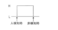
- the signal indicating the presence or absence of a person is a pulse signal of an H level when a person is detected and an L level when no person is detected, and the sensor control block 32 inputs these signals.
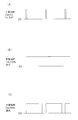
- a dimming signal that has been subjected to pulse width modulation (PWM) as shown in FIG. 27 is output to the illumination lighting device 33 such as an electronic ballast.
- PWM pulse width modulation
- a 5% duty PWM signal for fully lighting the discharge lamp 34 is output to the illumination lighting device 33.
- FIG. ) And (C) a PWM signal with a duty of 100% for turning off the discharge lamp 34 or a PWM signal with a duty of 85% for lighting at low illuminance is output to the illumination lighting device 33.
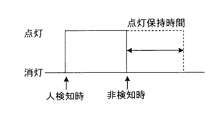
- the sensor control block 32 also sets the lighting holding time after detecting a person, and does not turn off the discharge lamp 34 immediately after the person is gone. For example, as shown in FIG. Control to maintain. This is because, for example, in a lighting system such as a staircase, if the light is turned off immediately after the person is no longer detected, it may be difficult to move up and down the staircase.
- an illumination system that detects the ambient brightness due to daylight using an illuminance sensor and automatically controls the lighting fixture to an appropriate amount of light according to the detected brightness.
- this illumination system when the outdoor is bright, it is lit at low illuminance, and when it is dark, it is lit at high illuminance, so that an illumination environment with constant brightness is always obtained (for example, Patent Documents 1 and 2). reference).
- FIG. 29 is a diagram showing a schematic configuration of an illumination system using an illuminance sensor.
- a brightness signal detected by the illuminance sensor 41 is sent to the sensor control block 42 as a DC signal of 5V when bright and 1V when dark.
- the sensor control block 42 outputs, for example, a PWM dimming signal as illustrated in FIG. 31 to the illumination lighting device 43 in accordance with the signal input from the illuminance sensor 41.
- the illuminance sensor 41 detects that the ambient brightness is dark, as shown in FIG. 31A, a 5% duty PWM signal for fully lighting the discharge lamp 34 is output to the illumination lighting device 43, which is bright. 31B, a PWM signal with a duty of 85% is output to the illumination lighting device 43 to adjust the light, and the light output of the discharge lamp 34 is reduced, as shown in FIG.
- the spatial illuminance can be controlled to be substantially constant regardless of day and night.
- the illuminance of the spatial illuminance to be controlled can be changed by arbitrarily adjusting the relationship between the output signal of the illuminance sensor 41 and the dimming signal of the sensor control block 42.
- a dimmer that outputs a PWM signal to an illumination lighting device in order to arbitrarily adjust the brightness of the illumination environment.
- FIG. 33 is a diagram showing a schematic configuration of an illumination system that controls the brightness of an illumination environment using a dimmer.
- the PWM signal output from the dimmer 51 is input to the illumination lighting device 53.
- the illumination lighting device 53 increases the light output of the discharge lamp 34 and turns on as shown in FIG. 34 (B).
- the duty ratio is large, the illumination lighting device 53 decreases the light output of the discharge lamp 34.
- FIG. 34C when the on-duty ratio is 100%, the illumination lighting device 53 turns off the discharge lamp 34. In this manner, a person can adjust the volume of the dimmer 51 and change the duty ratio of the PWM signal output from the dimmer 51 to obtain a desired illuminance.
- the signal form and illumination control such as lighting, dimming, and extinction are different.
- the control blocks are provided separately.
- the present invention has been made in view of the above circumstances, and when performing illumination control by connecting external devices such as a human body detection sensor, an illuminance sensor, and a dimmer, versatility is not incurred. It is an object to provide an illumination lighting device, a lighting fixture, and an illumination system that can be improved. Another object of the present invention is to provide an illumination lighting device capable of supplying a larger preheating current in a short preheating time. It is another object of the present invention to provide an illumination lighting device capable of reducing power consumption and saving energy during lamp lighting or standby preheating.
- the present invention provides, as an external device, any one of a human body detection sensor that detects the presence or absence of a person, an illuminance sensor that detects the illuminance of the space, and a dimmer that arbitrarily adjusts the illuminance of the space.
- an illumination lighting device that generates an output control signal for controlling the light output of a light source based on a signal output from the external device, and based on a signal output from the external device
- an illumination lighting device comprising: an external device determination unit that determines the type of the connected external device; and a signal processing unit that generates the output control signal based on a signal output from the external device.
- the present invention provides the illumination lighting device according to the second aspect, wherein the signal output from the external device includes an external device determination signal unique to each external device and a lighting operation of the light source.
- a lighting operation control signal peculiar to each of the external devices for controlling, and the external device determination unit determines the type of the connected external device from the external device determination signal, and the signal The processing unit is notified, and the signal processing unit includes a unit that generates the output control signal from the lighting operation control signal corresponding to the notified type of the external device.
- this invention is said illumination lighting device as said 3rd aspect, Comprising:
- the signal output from the said external device consists of the said lighting operation control signal,
- determination part is the said lighting operation control. From the signal, the type of the connected external device is determined and notified to the signal processing unit, and the signal processing unit corresponds to the notified type of the external device from the lighting operation control signal. Includes those that generate output control signals.
- This configuration there is no need to provide a special signal line for determining the connected external device, and the connected external device is determined using only the lighting operation control signal. Therefore, it is possible to provide an illumination lighting device that is versatile without causing an increase in cost.
- this invention is said illumination lighting device as 4th aspect, Comprising:
- the signal form of the said lighting operation control signal output from the said human body detection sensor is the said light source according to the presence or absence of the said person. It is a binary signal for turning on or off, and a signal form of the lighting operation control signal output from the illuminance sensor changes according to the illuminance of the space, and controls the output of the light source to control the space.
- the lighting mode control signal output from the dimmer controls the output of the light source by changing the duty ratio, so that the illuminance of the space is constant.
- the external device determination unit determines the type of the external device depending on which signal form the lighting operation control signal is in. Including the.
- the present invention provides, as a fifth aspect, the illumination lighting device according to any one of the above, wherein the light source is a discharge lamp, and the preheating current is supplied to the electrode of the discharge lamp.
- a preheating circuit having at least a first preheating current and a second preheating current, switchable to a plurality of stages, a timer unit for setting a preheating time for supplying the preheating current to the preheating circuit, and a preheating current output from the preheating circuit
- a preheating control unit that switches the supply amount of the battery, and the preheating control unit re-lights a second preheating current that is larger than the first preheating current at the time of lighting when re-lighting after the discharge lamp is turned off.
- It includes one that switches the preheating circuit to supply it as a preheating current.
- this invention is said illumination lighting device as said 6th aspect, Comprising:
- the said preheating control part preheats at the time of extinguishing 1st preheating current smaller than said 2nd preheating current at the time of discharge lamp extinction It includes one that switches the preheating circuit to supply it as an electric current. With this configuration, by continuing to supply a small preheating current after the light is turned off, it is possible to reduce power consumption and shorten the time until the light is turned on when the light is turned on again.
- this invention is said illumination lighting device as said 7th aspect, Comprising:
- the said timer part sets the preheating stop time which stops supply of the said preheating current
- the said preheating control part is the said discharge lamp. After the preheating stop time elapses when the light is turned off, the supply of the preheating current when the light is turned off from the preheating circuit is stopped. With this configuration, it is possible to suppress an increase in power consumption by stopping the supply of the preheating current after the preheating stop time has elapsed.
- this invention is said illumination lighting device as an 8th aspect, Comprising:
- the said timer part sets the 1st lighting preheating time and the 2nd lighting preheating time as said preheating time
- the preheating control unit supplies the first preheating current as the first lighting preheating current until the first lighting preheating time elapses when the power is turned on, and after the first lighting preheating time has elapsed.
- the second heating preheating current is switched to switch the preheating circuit to supply a second preheating current larger than the first preheating current.
- this invention is said illumination lighting device as 9th aspect, Comprising:
- the said preheating control part preheats during lighting a 1st preheating current smaller than a said 2nd preheating current after discharge lamp lighting. It includes one that switches the preheating circuit to supply it as an electric current. With this configuration, it is possible to reduce power consumption during lighting of the discharge lamp by supplying a small preheating current during lighting.
- the present invention is the illumination lighting device according to the tenth aspect, in which the timer unit sets a time for supplying the reheating preheating current at the time of relighting after the discharge lamp is turned off for 0.5 seconds. Including those set as follows. With this configuration, it is possible to shorten the time until the discharge lamp is lit again. For example, when the discharge lamp is installed in a place where people come and go, such as a corridor, the discharge lamp is turned on after a person passes by. Inconvenience can be prevented.
- this invention is said illumination lighting device as said 11th aspect, Comprising:
- the said timer part counts the frequency
- the present invention is the illumination lighting device according to a twelfth aspect, wherein the timer unit includes a time counter unit that counts the lighting time of the discharge lamp, It includes one that changes at least one of the supply time for supplying the second preheating current and the magnitude of the second preheating current.
- the timer unit includes a time counter unit that counts the lighting time of the discharge lamp, It includes one that changes at least one of the supply time for supplying the second preheating current and the magnitude of the second preheating current.
- the present invention provides, as a thirteenth aspect, a lighting fixture comprising any one of the above lighting lighting devices and the light source that is turned on when power is supplied from the lighting lighting device.
- a lighting fixture comprising any one of the above lighting lighting devices and the light source that is turned on when power is supplied from the lighting lighting device.
- this invention provides the lighting system which has said lighting fixture and the external apparatus connected to the said lighting fixture as a 14th aspect. With this configuration, it is possible to automatically determine the connected external device, perform appropriate lighting control corresponding to the external device, and provide a highly versatile lighting system.
- the illumination lighting device when connecting external devices, such as a human body detection sensor, an illumination sensor, and a light controller, and performing illumination control, the illumination lighting device which can improve versatility without incurring a cost increase , Lighting fixtures and lighting systems can be provided. Moreover, according to this invention, the illumination lighting device which can supply a larger preheating current in a short preheating time can be provided. Further, it is possible to provide an illumination lighting device capable of reducing power consumption and saving energy when the lamp is lit or during standby preheating.
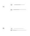
- explanatory drawing which shows the mode of each output of an output control signal and electronic ballast in case the connected external apparatus is a dimmer.
- explanatory drawing which shows the mode of each output of an output control signal and an electronic ballast in case the connected external apparatus is an illumination intensity sensor.
- Operation explanatory diagram showing a turn-off signal and a turn-on signal in the discharge lamp lighting device of the third embodiment The figure which shows the waveform of the preheating current If and the output voltage Vla in the discharge lamp lighting device of 3rd Embodiment.
- the figure which shows schematic structure of the discharge lamp lighting device which concerns on the 6th Embodiment of this invention The figure which shows the waveform of the preheating current If and the output voltage Vla in the discharge lamp lighting device of 6th Embodiment.
- the figure which shows the waveform of the preheating current If and the output voltage Vla at the time of re-lighting from the extinction of the discharge lamp lighting device which concerns on 7th Embodiment The figure which shows schematic structure of the discharge lamp lighting device which concerns on the 8th Embodiment of this invention.
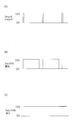
- A In the conventional lighting system, when a human is detected by the human body detection sensor, a diagram showing a signal output from the sensor control block to the lighting device.
- B In the conventional lighting system, the human body detection sensor
- C In the conventional lighting system, when a person is not detected by the human body detection sensor, the signal is output from the sensor control block to the illumination lighting device.
- A Diagram showing signals output from the illuminance sensor to the sensor control block when the surroundings are bright in the conventional lighting system.
- FIG. 1 is a diagram showing a schematic configuration of an illumination system according to the first embodiment of the present invention.
- the illumination system 1 of the present embodiment includes an illumination lighting device 11, an external device 12 connected to the illumination lighting device 11, and a discharge lamp 13 that is turned on when power is supplied from the illumination lighting device 11. It is the composition which has.
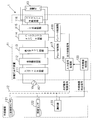
- the illumination lighting device 11 of the illumination system 1 in the present embodiment includes an input filter circuit 111, a full-wave rectifier circuit 112, a boost chopper circuit 113, a half-bridge inverter circuit 114, an LC resonance circuit 115, a filament preheating circuit 116, and a chopper controller 117.
- the input signal processing unit 119 and the external device determination unit 120 are added to a general electronic ballast composed of the inverter control unit 118.
- the input filter circuit 111 is connected to the commercial power supply AC and prevents high frequency noise from being superimposed on the power supply line.
- the full-wave rectifier circuit 112 performs full-wave rectification on the commercial power supply from which high-frequency noise has been removed, and the boost chopper circuit 113 chops the rectified DC voltage to provide a constant high voltage (chopper voltage Vdc) that serves as the inverter power supply. ).
- the half-bridge inverter circuit 114 is a half-bridge saddle type inverter circuit in which a series circuit composed of switching elements is connected between both ends of a smoothing capacitor, and the chopper voltage Vdc is switched when the switching elements are alternately turned on and off, and a high frequency Convert to the square wave voltage.
- the LC resonance circuit 115 generates a substantially sinusoidal voltage by a resonance action by inputting a rectangular wave voltage from the half-bridge inverter circuit 114.
- the generated substantially sinusoidal voltage is applied to both ends of the discharge lamp 13 to light the discharge lamp 13.
- the filament preheating circuit 118 preheats the filament of the discharge lamp 13 to ensure lighting, and does not impair the rated life of the discharge lamp 13.
- the chopper control unit 117 controls the switching operation of the switching elements included in the boost chopper circuit 113.
- the inverter control unit 118 controls the switching frequency included in the half-bridge inverter circuit 114, and substantially determines the light output of the discharge lamp 13.
- the switching frequency changes according to the output control signal input from the input signal processing unit 119.
- the switching frequency decreases, and the light output of the discharge lamp 13 increases due to the frequency characteristics of the LC resonance circuit 115 and the impedance of the discharge lamp 13. Further, when the output control signal decreases, the switching frequency increases and the light output of the discharge lamp 13 decreases.
- the input signal processing unit 119 inputs a lighting operation control signal sent from the external device 12, changes the signal processing form based on the type of the external device 12 determined by the external device determination unit 120, and determines the type of the external device 12 Is converted into a DC output control signal corresponding to.
- the external device determination unit 120 receives an external device determination signal sent from the external device 12, determines the type of the external device 12, and sends the determination result to the input signal processing unit 119.
- the external device 12 includes a human body detection sensor 121, an illuminance sensor 122, and a dimmer 123.
- the human body detection sensor 121 detects the presence / absence of a person using infrared rays emitted from the human body, and outputs an H level or L level lighting operation control signal to the input signal processing unit 119 of the lighting device 11.
- the illuminance sensor 122 detects ambient brightness due to daylight, and outputs a lighting operation control signal having a DC voltage of 0 to 5 V to the input signal processing unit 119 of the illumination lighting device 11 according to the detected brightness.
- the dimmer 123 outputs a PWM signal having a constant frequency to the input signal processing unit 119 of the lighting device 11 in order to arbitrarily control the brightness of the lighting environment.
- the human body detection sensor 121, the illuminance sensor 122, and the dimmer 123 each output a unique external device determination signal to the external device determination unit 120 of the illumination lighting device 11.
- an illumination lighting device configured by adding an input signal processing unit and an external device determination unit to a general electronic ballast. Since the connected external device is automatically determined and lighting control corresponding to the determined external device is performed, versatility can be improved. In addition, since it is not necessary to provide a sensor control block, the configuration is simplified and the cost can be reduced.
- FIG. 2 is a diagram showing a schematic configuration of an illumination system according to the second embodiment of the present invention.
- symbol is attached
- the illumination system 2 of the present embodiment includes an illumination lighting device 21, an external device 22 connected to the illumination lighting device 21, and a discharge lamp 13 that is turned on when power is supplied from the illumination lighting device 11. It is the composition which has.
- the illumination lighting device 21 of the illumination system 1 of the present embodiment has a configuration including an external device determination unit 220 instead of the external device determination unit 120 of the illumination lighting device 11 shown in the first embodiment.
- the external device 22 includes a human body detection sensor 221, an illuminance sensor 222, and a dimmer 223, and outputs a lighting operation control signal to the input signal processing unit 119 and the external device determination unit 220, respectively.
- the external device determination unit 220 receives the lighting operation control signal sent from the external device 22, determines the type of the connected external device 22, and sends the determination result to the input signal processing unit 119.
- FIG. 3 is a flowchart for explaining a method of discriminating the type of connected external device 22 in the external device discriminating unit 220.
- step S101 when the lighting system 2 is powered on, a lighting operation control signal is input from the connected external device 22 to the external device determination unit 220 of the lighting device 21 (step S102).
- the external device determination unit 220 checks whether or not the input signal is a PWM signal having a frequency of 1 kHz (step S103). If the input signal is a PWM signal having a frequency of 1 kHz, the connected external device is a dimmer. It is determined that it is H.223 (step S104).
- the input signal processing unit 119 performs signal processing corresponding to the dimmer 223 of the input lighting operation control signal, and outputs an output control signal corresponding to the duty ratio of the PWM signal to the inverter control unit 118 (step S105). ).
- FIG. 4 shows how the level of the output control signal changes and the output level of the electronic ballast supplied to the discharge lamp 13 changes according to the ON duty ratio of the PWM signal of the input lighting operation control signal.
- FIG. 4 As shown in the figure, as the on-duty ratio of the PWM signal increases, the level of the output control signal and the output level of the electronic ballast decrease.
- the input signal is a DC voltage in the range of 1 to 4V in step S106. It is checked whether or not.
- step S107 if the input signal is a DC voltage in the range of 1 to 4 V, it is determined that the connected external device is the illuminance sensor 222 (step S107).
- the input signal processing unit 119 performs signal processing corresponding to the illuminance sensor 222 of the input lighting operation control signal, and outputs an output control signal corresponding to the DC voltage level in the range of 1 to 4 V to the inverter control unit 118 (step) S108).
- FIG. 5 is a diagram showing a state in which the level of the output control signal changes according to the DC voltage level of the input lighting operation control signal, and the output level of the electronic ballast supplied to the discharge / discharge lamp 13 changes. It is. As shown in the figure, as the DC voltage level increases, the output control signal level and the output level of the electronic ballast decrease.
- the connected external device is the human body detection sensor 221 in step S109. (Step S109).
- the input signal processing unit 119 performs signal processing corresponding to the human body detection sensor 221 of the input lighting operation control signal. If the signal is 0V, the discharge lamp 13 is turned off. If the signal is 5V or more, the discharge lamp is discharged. An output control signal for lighting 13 is output to the inverter control unit 118. Further, the lighting holding time after detecting the presence of a person and turning on and detecting the absence of a person is set and output to the inverter control unit 118 (step S110).
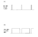
- FIG. 6A is a diagram showing a state in which the discharge lamp 13 is turned off or turned on according to the Low signal and High signal of the input lighting operation control signal. As shown in the figure, if the low signal is 0V, the level of the output control signal and the output level of the electronic ballast are set to 0, the discharge lamp 13 is turned off, and if the signal is 5V or higher, the output control signal And the electronic ballast is fully output and the discharge lamp 13 is turned on.
- FIG. 6B shows a state in which the discharge lamp 13 is turned on when a person is detected, and when the person is no longer detected, a lighting holding time is set in the input signal processing unit 119 and the lighting is continued. ing.
- the type of the external device to be connected is automatically set based only on the lighting operation control signal output from the external device. Therefore, appropriate lighting control corresponding to an external device can be performed, and versatility can be improved. Further, since there is no need to provide a sensor control block, the configuration is simplified and the cost can be reduced.
- FIG. 1 An example of a conventional lighting device is shown in FIG.
- a commercial power supply 301 is connected to the input of the lighting device 330 via a switch 302, and a lamp 338 which is a hot cathode fluorescent lamp is connected to the output.
- the lighting device 330 includes a filter circuit 331, a rectifier circuit 332, an inverter circuit 333, and a resonance circuit 334 in this order from the input side, and is connected to a lamp 338 serving as a load.
- the rectifier circuit 332 includes bridge-structured diodes D1 to D4 and a relatively large capacitor C2 such as an aluminum electrolytic capacitor, and full-wave rectifies the AC voltage of the commercial power supply 301. Smoothing to a substantially constant DC voltage.
- the inverter circuit 333 is connected to the output stage of the rectifier circuit 332 and has a configuration in which two switching elements such as MOSFETs are connected in series. By alternately switching the two switching elements Q1 and Q2 at a high frequency of about 50 kHz, a high-frequency rectangular wave voltage is generated at both ends of the switching element. Therefore, the DC voltage smoothed by the rectifier circuit 332 is changed to a high-frequency voltage. Can be converted.
- a choke coil L1, a resonance capacitor C3, and a DC cut capacitor C4 are connected in series with the switching element Q2 of the inverter circuit 333, and the rectangular wave voltage of the inverter circuit 333 is changed to a sine wave voltage. Converted and supplied to the lamp 338.
- the resonance capacitor C3 is connected to the choke coil L1 and the DC cut capacitor C4 via the respective electrodes of the lamp 338. When the lamp 338 is lit, the current flowing through the resonance circuit 334 is supplied to the electrode of the lamp 338. This is also used as a preheating current for heating.
- the equivalent impedance of the lamp 338 is extremely large compared to when the lamp 338 is lit, so that it is possible to easily obtain a high voltage necessary for starting the discharge of the lamp 338 at both ends of the resonant capacitor C4. Become.
- the inverter control circuit 335 controls the power supplied to the lamp 338 by changing the operating frequency of the inverter circuit 333 and using the fact that the impedance of the resonance circuit 334 changes according to the frequency.
- the inverter control circuit 335 is connected to a timer circuit 336 that measures the time from the start of the operation of the inverter circuit 333. Based on the measurement time of the timer circuit 336, the preheating time tp for heating the electrodes of the lamp 338 and the lamp 338 By controlling the timing of applying the high voltage Vs between the electrodes, the lamp 338 can be reliably turned on.
- the inverter control circuit 335 and the timer circuit 336 are available as ICs that integrate these functions, and can be easily configured by using, for example, an IC such as IR2156 manufactured by International Rectifier (IR).
- the inverter circuit 333 has switching elements Q1 and Q2 and performs a switching operation at a high frequency. Therefore, the inverter circuit 333 generates switching noise. This noise or the like is transmitted to other electronic devices or the like via the power supply line. The high frequency noise is cut by the filter circuit 331 so as not to cause a problem. By using such a lighting device, it is possible to improve the light emission efficiency of the discharge lamp and to save energy of the lighting fixture.
- an increasing number of lighting fixtures can be used to turn off the discharge lamp when there is no person using a human sensor.
- the preheating time tp for heating the electrode is provided for about 1.0 to 1.5 seconds, the time from when the sensor detects a person to when the lamp is lit is 1. A time delay of about 5 seconds may occur, causing the user to feel uncomfortable.
- preheating time tp is 0.5 second or less.
- the preheating current If when the preheating current If is supplied to heat the electrodes before applying a high voltage to the lamp 338 to start discharging, the preheating current If is supplied to the capacitor C3. To be supplied to both electrodes. Therefore, the voltage Vp is generated between both ends of the capacitor by the preheating current and the impedance of the capacitor C3, and this voltage is applied as it is between the electrodes of the lamp 338.
- This voltage Vp is given by the following equation according to the preheating current Ifp, the capacitor capacitance C3, and the operating frequency fp of the inverter circuit.
- the lamp 338 may start discharging.
- the lamp 338 is discharged before the electrode is sufficiently heated, and when discharge is started in this state, Big damage is done. Further, when the lamp 338 is repeatedly turned on and off, the electrode emitter is consumed and the life of the lamp 338 is shortened.
- the preheating current If when the preheating time tp is 0.5 seconds is in the optimum range of 0.68 A or more and 1.442 A or less.
- the electrical characteristics supplied from the lighting device 330 to the lamp 338 are as follows, and the voltage applied to the lamp at the time of preheating is equal to or higher than the voltage necessary for starting the lamp. Before it is heated, the lamp is turned on, which causes great damage to the electrodes.
- the conventional lighting device shown in FIG. 7 has many design constraints and is difficult to realize.
- a preheating circuit is used by using a preheating transformer T2. This can be realized by providing it separately from the resonance circuit.
- the preheating current is increased, the preheating current is increased even during lighting, and there is a problem that unnecessary power at the electrodes increases.
- Patent Document 3 proposes a discharge lamp lighting device that can supply a preheating current even after the sensor is extinguished to enable instant lighting.
- the discharge lamp lighting device disclosed in Patent Document 3 is driven by a DC power supply, an inverter circuit that converts the output of the DC power supply into high-frequency power, a resonance circuit connected to the output of the inverter circuit, and a resonance action of the resonance circuit.
- the first period Tb in which the level of the preheating current If is set high and the second period Ta in which the level of the preheating current is set low are alternately switched, and the first period Tb is the second period.
- a method is adopted in which a preheating current that does not light the discharge lamp is continuously supplied to the electrodes by setting it sufficiently shorter than Ta. As a result, instantaneous lighting is possible.
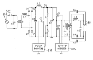
- FIG. 10 is a diagram showing a schematic configuration of a discharge lamp lighting device according to the third embodiment of the present invention.
- FIG. 11 is a characteristic diagram showing the frequency characteristics of the output voltage Vo of the load circuit 306 and the preheating current If by the preheating circuit 305 in the discharge lamp lighting device of the third embodiment.
- a commercial power supply 301 is connected to the input of the discharge lamp lighting device shown in FIG. 10 via a switch 302, and a lamp 308, which is a hot cathode fluorescent lamp, is connected to the output.
- This discharge lamp lighting device is configured from the input side in the order of a rectifier circuit 303, an inverter circuit 304, a preheating circuit 305, and a load circuit 306, and is connected to a lamp 308 serving as a load.
- the rectifier circuit 303 is connected to a DC power source and has at least one switching element Q3 connected to a DC power source and bridge-structured diodes D1 to D4 for full-wave rectification of the AC power source AC input from the commercial power source 301. And a chopper circuit that converts a DC voltage from a DC power source into a predetermined DC voltage, and a relatively large capacitor C2 such as an aluminum electrolytic capacitor.
- This rectifier circuit 303 full-wave rectifies the AC voltage of the commercial power supply 301 and smoothes it to a substantially constant DC voltage.
- the input AC power supply AC is a commercial AC power supply, and the voltage is, for example, 100V, 200V, or 240V.
- the diodes D1 to D4 rectify an AC voltage from the AC power supply AC into a pulsating voltage and output it.
- the chopper circuit is a step-up AC-DC converter, which boosts the power supply voltage full-wave rectified by the rectifier circuit 303 to a predetermined DC voltage and outputs it.
- the chopper circuit is configured such that the choke coil L2 and the diode D5 are inserted in series between one end of the output stage of the diode bridges D1 to D4 of the rectifier circuit 303 and the smoothing capacitor C2, and the choke coil L2 and the diode D5 are connected.
- a switching element Q3 such as a MOSFET is connected between the connection point and the other end of the output stage of the diode bridges D1 to D4.
- a choke coil L3 is inserted between the filter T1 and the diode bridges D1 to D4, and a capacitor C8 is inserted in parallel at the output stage of the diode bridges D1 to D4.
- the choke coil L3 and the capacitor C8 constitute a filter circuit.
- step-up chopper circuit is described here, other chopper circuits such as a step-down type and a step-up / step-down type may be used, and the operation and effects are not changed as long as the AC voltage of the commercial power supply 301 can be converted into a DC voltage. .
- the inverter circuit 304 is connected to the output stage of the rectifier circuit 303 and has a configuration in which two switching elements such as MOSFETs are connected in series. By switching the two switching elements Q1 and Q2 alternately at a high frequency of about 50 kHz, a high-frequency rectangular wave voltage is generated at both ends of the switching element, so that the DC voltage smoothed by the rectifier circuit 303 is changed to a high-frequency voltage. Can be converted.
- the inverter circuit As the inverter circuit, a so-called half-bridge type inverter circuit is employed in the present embodiment.
- the inverter circuit may be a full bridge type, a single stone type, or a push-pull type.
- the preheating circuit 305 includes a transformer T2, and one end of the primary winding n1 of the transformer T2 is connected to the output stage of the inverter circuit 304 via a DC cut capacitor C5. Further, windings n2 and n3 are provided on the secondary side of the transformer T2 so that the two electrodes of the lamp 308 can be heated separately, and are connected to the respective electrodes via capacitors C6 and C7. . Further, a switching element Q4 such as a capacitor C9 and a MOSFET is provided, and is connected in parallel between the other end of the primary side winding n1 of the transformer T2 and the output stage of the inverter circuit 304. Control to supply a predetermined preheating current is performed by turning ON / OFF the switching element Q4.
- each electrode of the lamp is preheated using a voltage generated on the secondary side by the transformer T2 as a power source.
- Capacitors C6 and C7 function as a reduced impedance of the preheating current If of each filament.
- the capacitor C9 holds most of the voltage of the rectangular wave, so that almost no voltage is generated on the secondary side of the transformer T2. Therefore, the current for preheating each electrode of the lamp can be suppressed.
- the supply amount of preheating current is controlled by switching element Q4. can do.
- the current when the switching element Q4 is OFF is referred to as a first preheating current Ifp1
- the current when the switching element Q4 is ON is referred to as a second preheating current Ifp2.
- the load circuit 306 includes a choke coil L1, a resonance capacitor C3, and a DC cut capacitor C4 connected in series with the switching element Q2 of the inverter circuit 304.
- the load circuit 306 converts the rectangular wave voltage of the inverter circuit 304 into a sine wave voltage and supplies it to the lamp 308.
- the control circuit 307 includes a chopper control circuit 371, an inverter control circuit (inverter control unit) 372, a preheating control circuit (preheating control unit) 373, a timer circuit (timer unit) 374, and a turn-off control unit 310.
- the chopper control circuit 371 controls switching of the switching element Q3, and detects the voltage across the capacitor C2 by dividing it with resistors R1 and R2. Feedback control is performed so that the conduction time of the switching element Q2 becomes longer when the voltage across the capacitor C2 is lower than a predetermined voltage, and conversely when the voltage across the capacitor C2 is low. As a result, the voltage of the capacitor C2 can be controlled to be constant even if the power supply voltage or the state of the load changes.
- the inverter control circuit 372 controls the power supplied to the lamp 308 by using the fact that the impedance of the load circuit 306 changes depending on the frequency by changing the operating frequency of the inverter circuit 304.
- the inverter control circuit 372 is connected to a timer circuit 374 that measures the time from the start of the operation of the inverter circuit 304. Based on the measurement time of the timer circuit 374, a preheating time for heating the electrodes of the lamp 308 and the lamp 308 By controlling the timing of applying the high voltage Vs between the electrodes, the lamp 308 can be reliably turned on.
- the preheating control circuit 373 controls ON / OFF of the switching element Q4 of the preheating circuit 305.
- the preheating circuit 373 measures the preheating time for heating the electrodes of the lamp 308 by the timer circuit 374, and based on this measurement time, the preheating circuit 305 By controlling the ON / OFF timing of the switching element Q4, the preheating current can be freely switched between the first preheating current and the second preheating current, and the supply of the preheating current flowing through the electrode can be controlled. .
- the turn-off control circuit 310 outputs a turn-off signal and a turn-on signal and transmits them to the timer circuit 374.
- the extinguishing control circuit 310 transmits an extinguishing signal to the external signal 309 such as a sensor when no one is present, and transmits a lighting signal to the timer circuit 374 when a person is detected.
- FIG. 12 is an operation explanatory diagram showing a turn-off signal and a turn-on signal in the discharge lamp lighting device of the third embodiment.
- the extinguishment control circuit 310 performs control to transmit 0V as the extinguishing signal from time t0 to t1, and to transmit 5V as the lighting signal from time t1.
- the extinguishing control circuit 310 uses the output of a sensor or the like for detecting a person as the external signal 309 to perform control such as extinguishing when there is no person. It may be one that controls a DC voltage or one that controls a digital signal.
- the discharge lamp lighting device of the present embodiment is configured as described above, so that the output voltage Vo and the preheating current If during the preheating time (the lamp 308 is not lit) are as shown in FIG. It becomes frequency characteristic.
- the frequency f0 is a natural vibration frequency of the load circuit 306.
- the inverter control circuit 372 can increase the output voltage Vo of the load circuit 306 when the operating frequency of the inverter circuit 304 is brought close to f0 by changing the operating frequency of the inverter circuit 304, and the output voltage when moving away from f0. Vo can be lowered.
- the second preheating current Ifp2 is supplied when the switching element Q4 is ON.
- the preheating current is held by the capacitor C9 connected in parallel to the switching element Q4, and the first preheating current Ifp1 smaller than the second preheating current Ifp2 is supplied.
- the inverter control circuit 372 confirms that the operation time of the inverter circuit 304 has passed the preheating time by the timer circuit 374, and then shifts the operation frequency from fp to fs near f0 to light the lamp.
- the electrode of the lamp 308 can be optimally heated during a predetermined preheating time, and the voltage Vp applied between the electrodes can be lowered to a level at which the lamp 308 does not start discharging.
- the high voltage Vs is applied between the electrodes of the lamp 308 after the preheating time has elapsed, and the lamp can be reliably turned on without damaging the electrodes of the lamp 308. Therefore, it is possible to avoid shortening the life of the lamp 308 even if the number of times the lamp 308 is turned on increases.
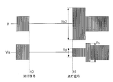
- FIG. 13 is a diagram showing waveforms of the preheating current If and the output voltage Vla of the load circuit 306 in the discharge lamp lighting device of the third embodiment, and shows operation waveforms at the time of re-lighting after turning off.
- the extinguishing control unit 310 transmits a extinguishing signal to the timer circuit 374 based on an external signal 309 such as a sensor, and when the extinguishing instruction is given, the inverter control circuit 372 receives the extinguishing signal via the timer circuit 374. Then, the inverter circuit 304 is stopped and the lamp 308 is turned off. At this time, the preheating current If and the output voltage Vla become zero.
- the inverter control circuit 372 receives the turn-on signal via the timer circuit 374.
- the operation frequency of the inverter circuit 304 is shifted to fp and operated, the switching element Q4 of the preheating circuit 305 is switched to ON by the preheating control circuit 373, and the second preheating current Ifp2 is supplied as the preheating current at the time of relighting.
- the electrode of the lamp 308 is preheated.
- the voltage Vp applied between the electrodes is a small voltage at which the lamp 308 does not start discharging. Thereafter, after the preheating time has elapsed, the operating frequency of the inverter circuit 304 is shifted from fp to fs, the high voltage Vs is applied between the electrodes of the lamp 308, and the lamp 308 is lit again.
- the preheating time for supplying the second preheating current Ifp2 at the time of re-lighting is 0.5 seconds or less.
- the preheating current may be set to three or more stages. The same applies to the following embodiments.
- FIG. 14 shows operation waveforms of the fourth embodiment of the present invention.
- FIG. 14 is a diagram showing the waveforms of the preheating current If and the output voltage Vla in the discharge lamp lighting device of the fourth embodiment, and shows the operation waveforms when the lamp is turned off.
- the inverter control circuit 372 shifts the operating frequency of the inverter circuit 304 to fp, In addition to turning off the light, the preheating control circuit 373 turns off the switching element Q4 of the preheating circuit 305, and supplies a smaller first preheating current Ifp1 as the preheating current when the light is turned off to preheat the electrodes of the lamp 308. In this way, when the light is turned off, the supply of the preheating current Ifp1 is continued, so that power consumption can be reduced and energy can be saved. In addition, when relighting, the time until lighting can be shortened. However, as described in the third embodiment, it is necessary to set the voltage Vp applied between the electrodes at this time to a level at which the lamp 308 does not start discharging.
- FIG. 15 is a diagram showing waveforms of the preheating current If and the output voltage Vla in the discharge lamp lighting device of the fifth embodiment, and shows operation waveforms when the lamp is turned off.
- the inverter control circuit 372 turns off the lamp 308 and the first preheating current Ifp1. Thus, the supply of preheating current is continued.
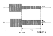
- the timer circuit 374 stores a predetermined time T3 (preheat stop time) which is a constant value, and compares the preheat stop time T3 with the measured preheat time to preheat.
- T3 preheat stop time
- the inverter control circuit 372 stops the inverter circuit 304 and stops the discharge lamp lighting device.
- the predetermined preheating stop time T3 is set to about 1 minute in order to suppress an increase in power consumption, for example.
- the switching element Q4 is turned on by the preheating control circuit 373 in the same manner as in the third embodiment, and the lamp 308 is turned on with the second preheating current Ifp2. Preheat and re-light the electrode.
- the increase in power consumption can be suppressed by stopping the supply of the preheating current Ifp1 after the preheating stop time has elapsed.
- FIG. 16 shows the configuration of the sixth embodiment of the present invention
- FIG. 17 shows the operation waveforms.
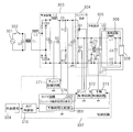
- FIG. 16 is a diagram showing a schematic configuration of a discharge lamp lighting device according to a sixth embodiment of the present invention
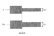
- FIG. 17 is a diagram showing waveforms of a preheating current If and an output voltage Vla in the discharge lamp lighting device of the sixth embodiment. The operation waveforms when the power is turned on are shown.
- a preheating time comparison unit 381 and an inverter operation time comparison unit 382 are provided in the timer circuit 374 in addition to the configuration of the third embodiment shown in FIG. Other configurations are the same as those in FIG.
- the timer circuit 374 stores a predetermined time T1 (first lighting preheating time) and T2 (second lighting preheating time), which are constant values, and compares the preheating time.
- the first lighting preheating time T1 and the second lighting preheating time T2 are compared with the measured preheating times by the unit 381.
- the preheating time comparison unit 381 compares the first lighting preheating time T1 with the measured preheating time, and the preheating control circuit 373 continues until the preheating time exceeds the first lighting preheating time T1.
- the switching element Q4 of the preheating circuit 305 is turned off, and the first preheating current Ifp1 is supplied to the electrode of the lamp 308 as the first lighting preheating current to preheat.
- the preheating control circuit 373 turns on the switching element Q4, switches to the second preheating current Ifp2 as the second lighting preheating current, and supplies it to the electrode of the lamp 308.
- the preheating time comparison unit 381 compares the second lighting preheating time T2 with the measured preheating time, and the preheating control circuit 373 keeps the second lighting preheating time T2 until the second lighting preheating time T2 is exceeded.
- a second preheating current Ifp2 is supplied as a current to preheat the lamp 308.
- the inverter operating time comparison unit 382 compares the first lighting preheating time T1 and the second lighting preheating time T2 with the measured inverter circuit operating time.
- the inverter control circuit 372 operates with the operating frequency of the inverter circuit 304 set to fp until the first lighting preheating time T1 and the second lighting preheating time T2 elapse according to the comparison of the inverter operating time comparison unit 382. .
- the operating frequency of the inverter circuit 304 is shifted to fs, and a high voltage Vs is applied between the electrodes of the lamp 308, and the lamp 308 is started.
- the electrode is preheated to some extent by supplying the first preheating current Ifp1 during the predetermined first lighting preheating time T1 only when the power is turned on.
- the first preheating current Ifp1 may be zero.
- the first lighting preheating time T1 for supplying the first preheating current Ifp1 and the second lighting preheating time T2 for supplying the second preheating current Ifp2 are set so as not to be uncomfortable for the user. There is a need to.
- the first and second lighting preheating times T1 and T2 are preferably set to about 2 seconds or less.
- FIGS. 18 is a diagram showing waveforms of the preheating current If and the output voltage Vla when the power supply is turned on in the discharge lamp lighting device of the seventh embodiment, and FIG. It is a figure which shows the waveform of the preheating current If and output voltage Vla.
- the inverter control circuit 372 sets the operating frequency of the inverter circuit 304 based on the time counted by the timer circuit 374 to fp ⁇ Switching from fs at start-up to fp at lighting.
- the preheating control circuit 373 turns off the switching element Q4 of the preheating circuit 305 and supplies the first preheating current Ifp1 as the preheating current during lighting.
- the preheating control circuit 373 turns off the switching element Q4 of the preheating circuit 305 as in the case of the lighting, so that the preheating current during lighting is obtained.
- a first preheating current Ifp1 is supplied.
- the seventh embodiment during lighting, by supplying the preheating current with the first preheating current Ifp1 smaller than the second preheating current Ifp2, it is possible to reduce the power consumption during lighting. .
- FIG. 20 The configuration of the eighth embodiment of the present invention is shown in FIG. 20, and the flowchart of the operation is shown in FIGS. 20 is a diagram showing a schematic configuration of a discharge lamp lighting device according to an eighth embodiment of the present invention
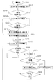
- FIG. 21 is a flowchart for explaining a first example of the operation of the discharge lamp lighting device of the eighth embodiment
- FIG. 22 is a flowchart for explaining a second example of the operation of the discharge lamp lighting device according to the eighth embodiment.
- the timer circuit 374 is provided with a number counter unit 383 and a nonvolatile memory 361, and the accumulated number of times stored in the nonvolatile memory 361 is calculated.
- a reset control unit 362 for resetting is provided.
- Other configurations are the same as those in FIG.
- the number counter unit 383 counts the number of operations of the turn-off signal from the external signal 309 such as a sensor or the second preheating current Ifp2.
- the nonvolatile memory 361 sequentially stores the counted number of turn-off signals or the number of operations of the second preheating current Ifp2.
- the control circuit 307 can freely change at least the second lighting preheating time T2 for supplying the second preheating current Ifp2 or the supply amount of the second preheating current Ifp2 according to the number of times. ing.
- the reset control unit 362 performs an operation of resetting the cumulative number stored in the nonvolatile memory 361 to the initial value (the cumulative number is zero) when the lamp 308 is replaced with a new one.
- Specific examples of the reset operation include a reset method by operating a reset button, a method of automatically detecting the end-of-life state of the lamp 308 and a method of resetting by a predetermined power ON / OFF operation. It is done.
- the nonvolatile memory 361 can be configured by a nonvolatile memory such as a general-purpose EEPROM or a flash memory built in a microprocessor.
- the first example shown in FIG. 21 is an example using only the number of operations of the second preheating current.
- the preheating control circuit 373 turns off the switching element Q4 of the preheating circuit 305 and supplies the first preheating current Ifp1 (step S312). Then, it is determined whether or not the first lighting preheating time T1 has elapsed (step S313), and when the time T1 has elapsed (step S313: Y), the preheating control circuit 373 turns on the switching element Q4 and performs the second preheating.
- the current Ifp2 is supplied (step S314).
- step S315) it is determined whether the second lighting preheating time T2 elapses (step S315), and when the time T2 elapses (step S315: Y), the number counter unit 383 determines the number of times the second preheating current Ifp2 is operated. Measurement is performed (step S316), and the number of operations is stored in the nonvolatile memory 361 (step S317).
- the timer circuit 374 can change the second preheating current time T2 in accordance with the number of operations of the second preheating current.
- the second preheating current time T2 is lengthened. As a result, the time for preheating the electrode becomes longer, so that the problem that the lamp has a short life can be avoided.
- the inverter control circuit 372 applies the high voltage Vs between the electrodes of the lamp 308, and turns on the lamp 308 (step S318).
- the operating frequency of the inverter circuit 304 is set to fp during the preheating time, and after the preheating time, the operating frequency of the inverter circuit 304 is shifted from fp to fs, and the lamp 308 is turned on.
- the preheating control circuit 373 turns off the switching element Q4 and supplies the first preheating current Ifp1 (step S319). Thereafter, the extinguishing control unit 310 determines whether the external signal is the lighting signal or the extinguishing signal (step S320). When the external signal is the extinguishing signal (step S320: N), the inverter control circuit 372 controls the inverter circuit 304. The lamp is turned off (step S321).
- step S322 it is determined whether the preheating stop time T3 elapses (step S322).
- step S322: Y the preheating control circuit 373 stops supplying the first preheating current Ifp1 (step S323).
- step S322: N the preheating control circuit 373 continues to supply the first preheating current Ifp1 (step S324).
- the extinguishing control unit 310 determines whether the external signal is a lighting signal or an extinguishing signal (step S325).
- step S325: Y If the external signal is a lighting signal (step S325: Y), the process returns to step S314 and the second preheating current Ifp2 is detected. Supply. On the other hand, when the external signal is a turn-off signal (step S325: N), the process returns to step S321 to turn off the lamp.
- the second example shown in FIG. 22 is a modification of the first example of FIG. 21, and uses the number of turn-off signals together with the number of operations of the second preheating current.
- the number counter unit 383 measures the number of times the turn-off signal is input (step S331), and stores this number in the nonvolatile memory 361 (step S332). ).
- the timer circuit 374 can change the second preheating current time T2 according to the number of turn-off signals.
- the second preheating current time T2 is lengthened. As a result, the time for preheating the electrode becomes longer, so that the problem that the lamp has a short life can be avoided.
- the second preheating time T2 it is possible to change the second preheating time T2 depending on the number of operations of the second preheating current and the number of turn-off signals, but as shown in FIG.
- the supply amount of the second preheating current Ifp2 can be freely changed as well.
- the number of operations of the second preheating current or the number of turn-off signals is stored in the nonvolatile memory 361, and the operation frequency fp of the inverter circuit 304 is gradually shifted to a higher frequency as the number increases. It is possible to increase the supply amount of the preheating current Ifp2. By setting in this way, it is possible to obtain an effect capable of preventing the lamp life from being shortened.
- FIG. 23 is a diagram showing a schematic configuration of a discharge lamp lighting device according to the ninth embodiment of the present invention
- FIG. 24 is a flowchart for explaining the operation of the discharge lamp lighting device of the ninth embodiment.
- the ninth embodiment is a modification of the eighth embodiment shown in FIG. 20, and a timer circuit 374 is provided with a time counter unit 384 instead of the number counter unit 383.
- Other configurations are the same as those in FIG.
- the time counter unit 384 counts the discharge lamp lighting time based on the output of the rectifier circuit 303.
- the lighting time starts counting when the time counter unit 384 of the timer circuit 374 receives the DC voltage from the rectifier circuit 303.
- the nonvolatile memory 361 sequentially stores the counted lighting time of the discharge lamp as the cumulative lighting time.
- the time counter unit 384 measures the lamp lighting time (step S341), and the lighting time is stored in the nonvolatile memory 361. (Step S342). At this time, for example, as shown in Table 5, the timer circuit 374 can change the second preheating current time T2 according to the lamp lighting time.
- the second preheating current time T2 is lengthened. As a result, the time for preheating the electrode becomes longer, so that the problem that the lamp has a short life can be avoided.
- the extinguishing control unit 310 determines whether the external signal is the lighting signal or the extinguishing signal (step S343).
- the time counter unit 384 measures the lamp lighting time.
- the process ends (step S344), and the nonvolatile memory 361 ends the storage of the cumulative lighting time (step S345).
- the inverter control circuit 372 controls the inverter circuit 304 to turn off the lamp.
- the supply amount of the second preheating current Ifp2 can be freely changed in the same manner by changing the operating frequency of the inverter circuit 304 according to the cumulative lighting time as in the eighth embodiment.
- the cumulative lighting time is stored in the nonvolatile memory 361, and as the time increases, the operation frequency fp of the inverter circuit 304 is gradually shifted to a higher frequency, thereby increasing the supply amount of the second preheating current Ifp2. Is possible. By setting in this way, it is possible to obtain an effect capable of preventing the lamp life from being shortened.
- At least the preheating time T2 for supplying the second preheating current Ifp2 or the supply amount of the second preheating current Ifp2 can be freely changed according to the cumulative lighting time of the lamp. It is possible to prevent the lamp life from being shortened.
- each component such as the chopper control circuit 371, the inverter control circuit 372, the preheating control circuit 373, the timer circuit 374, and the turn-off control unit 310 of the control circuit 307 uses a microcomputer.
- Each function of the above-described embodiment can be realized by executing a process corresponding to each operation by a processor and a program operating on the processor.
- the preheating current supplied to the electrode can be switched between two or more stages, and it is short when the lamp is turned on again after being turned off based on at least the sensor signal.
- a larger preheating current can be supplied in the preheating time. Further, when the lamp is turned on or during standby preheating, it is possible to reduce power consumption and save energy by supplying a smaller preheating current.
Landscapes
- Circuit Arrangement For Electric Light Sources In General (AREA)
Abstract
人体検知センサ、照度センサ及び調光器等の外部機器を接続して照明制御を行う場合に、コストの高騰を回避するとともに、汎用性を向上させる。 照明点灯装置11は、一般的な電子安定器に入力信号処理部119および外部機器判別部120を加えて構成される。照明点灯装置11に接続される外部機器12には、人体検知センサ121、照度センサ122及び調光器123が含まれ、それぞれに特有の点灯動作制御信号と外部機器判別信号を、それぞれ入力信号処理部119及び外部機器判別部120に出力する。外部機器判別部120は、外部機器判別信号に基づいて照明点灯装置11接続される外部機器の種類を判定し、入力信号処理部119は、判定した外部機器の種類に応じて点灯動作制御信号を処理して、出力制御信号をインバータ制御部118に送る。
Description
本発明は、人体検知センサや照度センサ、調光器等の外部機器を接続して、光源の点灯や消灯、調光を制御する照明点灯装置、照明器具、及び照明システムに関する。
従来、人体検知センサを用いて、人がいると検知された場合には高照度で点灯し、人がいないことが検知された時には低照度で点灯、若しくは消灯する照明システムが知られている(例えば、特許文献1参照)。
図25は、このような照明システムの概略構成を示す図である。同図において、人体検知センサ31によって検出した人の存否を示す信号は、センサ制御ブロック32に送出される。人の存否を示す信号は、例えば図26に示すように、人を検知した時はHレベル、人を検知しない時はLレベルのパルス信号であり、センサ制御ブロック32は、これらの信号を入力することによって、例えば、図27に示すようなパルス幅変調(PWM)された調光信号を電子安定器等の照明点灯装置33に出力する。
人を検知した時は、図27(A)に示すように、放電灯34をフル点灯させるデューティ5%のPWM信号を照明点灯装置33に出力し、人を検知しない時は、図27(B)、(C)に示すように、放電灯34を消灯させるデューティ100%のPWM信号、又は低照度で点灯させるデューティ85%のPWM信号を照明点灯装置33に出力する。
センサ制御ブロック32は、人を検知した後の点灯保持時間の設定も行い、人がいなくなった直後に放電灯34を消灯するのではなく、例えば、図28に示すように、数分間は点灯を維持するように制御する。これは、例えば階段等の照明システムにおいて、人を検知しなくなった直後に消灯すると、階段の昇降が困難になる場合があるからである。
また、照度センサを用いて昼光による周囲の明るさを検出し、検出した明るさに応じて照明器具を適切な光量に自動制御する照明システムがある。この照明システムでは、戸外が明るいときは低照度で点灯し、戸外が暗いときは高照度で点灯することで、常に一定の明るさの照明環境を得るものである(例えば、特許文献1、2参照)。
図29は、照度センサを用いる照明システムの概略構成を示す図である。同図において、照度センサ41によって検出された明るさ信号、例えば、図30(A)、(B)に示すように、明るい場合は5V、暗い場合は1Vの直流信号をセンサ制御ブロック42に送出する。センサ制御ブロック42は、照度センサ41から入力された信号に応じて、例えば、図31に示すようなPWM調光信号を照明点灯装置43に出力する。
照度センサ41で周囲の明るさが暗いと検出された場合は、図31(A)に示すように、放電灯34をフル点灯させるデューティ5%のPWM信号を照明点灯装置43に出力し、明るいと検出された場合は、図31(B)に示すように、デューティ85%のPWM信号を照明点灯装置43に出力しで調光し、放電灯34の光出力を低下させる。これにより、照度センサ41で検出される周囲の明るさによって、例えば図32に示すように、昼夜に拘わらず空間照度が常にほぼ一定となるように制御することができる。また、照度センサ41の出力信号と、センサ制御ブロック42の調光信号の関係を任意に調整することで、制御しようとする空間照度の照度を変更することが可能である。
更に、照明環境の明るさを任意に調整するために、PWM信号を照明点灯装置に出力する調光器の例がある。
図33は、調光器を用いて照明環境の明るさを制御する照明システムの概略構成を示す図である。同図において、調光器51から出力されるPWM信号は照明点灯装置53に入力される。例えば、このPWM信号のオンデューティ比が、図34(A)に示すように小さい場合には、照明点灯装置53は放電灯34の光出力を増加させ、図34(B)に示すようにオンデューティ比が大きい場合は、照明点灯装置53は放電灯34の光出力を減少させる。また、図34(C)に示すようにオンデューティ比が100%の場合、照明点灯装置53は放電灯34を消灯させる。このように、人が調光器51のボリュームを調整し、調光器51から出力されるPWM信号のデューティ比を変更することで、所望の照度を得ることができる。
以上説明したように、人体検知センサや照度センサ、調光器等の外部機器を用いる従来の照明システムにおいては、信号形態および点灯、調光、消灯といった照明制御が異なるため、それぞれに対応したセンサ制御ブロックを個別に設けるのが一般的であった。
しかしながら、外部機器ごとに個別にセンサ制御ブロックを設けることは、コストアップを招くと共に、汎用性に乏しいという問題をも惹起する。
本発明は、前記実情に鑑みてなされたもので、人体検知センサ、照度センサ及び調光器等の外部機器を接続して照明制御を行う場合に、コストアップを招くことがなく、汎用性を向上させることのできる照明点灯装置、照明器具、及び照明システムを提供することを目的とする。
また、本発明は、短い予熱時間でより大きな予熱電流を供給することが可能な照明点灯装置を提供することを目的とする。また、本発明は、ランプ点灯時や待機予熱時において消費電力を低減させ省エネルギーを図ることが可能な照明点灯装置を提供することを目的とする。
また、本発明は、短い予熱時間でより大きな予熱電流を供給することが可能な照明点灯装置を提供することを目的とする。また、本発明は、ランプ点灯時や待機予熱時において消費電力を低減させ省エネルギーを図ることが可能な照明点灯装置を提供することを目的とする。
本発明は、第1の態様として、外部機器として、人の存否を検知する人体検知センサと、空間の照度を検出する照度センサと、前記空間の照度を任意に調整する調光器のいずれかが接続され、前記外部機器から出力される信号に基づいて、光源の光出力を制御するための出力制御信号を生成する照明点灯装置であって、前記外部機器から出力される信号に基づいて、接続された前記外部機器の種類を判別する外部機器判別部と、前記外部機器から出力される信号に基づいて、前記出力制御信号を生成する信号処理部と、を具備した照明点灯装置を提供する。
この構成により、接続された外部機器を自動的に判別して、外部機器に対応する適切な点灯制御が可能となり、汎用性の高い照明点灯装置を提供することができる。また、外部機器ごと個別にセンサ制御ブロックを設ける必要がないので、構成が簡単になり、コストを抑えることができる。
この構成により、接続された外部機器を自動的に判別して、外部機器に対応する適切な点灯制御が可能となり、汎用性の高い照明点灯装置を提供することができる。また、外部機器ごと個別にセンサ制御ブロックを設ける必要がないので、構成が簡単になり、コストを抑えることができる。
また、本発明は、第2の態様として、上記の照明点灯装置であって、前記外部機器から出力される信号は、前記外部機器それぞれに特有の外部機器判別信号と、前記光源の点灯動作を制御するための、前記外部機器それぞれに特有の点灯動作制御信号と、からなり、前記外部機器判別部は、前記外部機器判別信号から、接続された前記外部機器の種類を判別して、前記信号処理部に通知し、前記信号処理部は、通知された前記外部機器の種類に対応して、前記点灯動作制御信号から前記出力制御信号を生成するものを含む。
この構成により、接続された外部機器を自動的に判別して、外部機器に対応する適切な点灯制御が可能となり、汎用性の高い照明点灯装置を提供することができる。
この構成により、接続された外部機器を自動的に判別して、外部機器に対応する適切な点灯制御が可能となり、汎用性の高い照明点灯装置を提供することができる。
また、本発明は、第3の態様として、上記の照明点灯装置であって、前記外部機器から出力される信号は、前記点灯動作制御信号からなり、前記外部機器判別部は、前記点灯動作制御信号から、接続された前記外部機器の種類を判別して、前記信号処理部に通知し、前記信号処理部は、通知された前記外部機器の種類に対応して、前記点灯動作制御信号から前記出力制御信号を生成するものを含む。
この構成により、接続された外部機器を判別するための信号線を特別に設ける必要がなく、点灯動作制御信号のみを用いて接続された外部機器の判別を行うので、既存の外部機器であっても対応することができ、コストアップを招くことがなく、汎用性に富む照明点灯装置を提供することが可能となる。
この構成により、接続された外部機器を判別するための信号線を特別に設ける必要がなく、点灯動作制御信号のみを用いて接続された外部機器の判別を行うので、既存の外部機器であっても対応することができ、コストアップを招くことがなく、汎用性に富む照明点灯装置を提供することが可能となる。
また、本発明は、第4の態様として、上記の照明点灯装置であって、前記人体検知センサから出力される前記点灯動作制御信号の信号形態は、前記人の存否に応じて、前記光源を点灯、或いは消灯するための2値信号であり、前記照度センサから出力される前記点灯動作制御信号の信号形態は、前記空間の照度に応じて変化し、前記光源の出力を制御して前記空間の照度を一定にするための直流電圧であり、前記調光器から出力される前記点灯動作制御信号の信号形態は、デューティ比を変化させることによって前記光源の出力を制御し、前記空間の照度を所望の値に制御するための周波数が一定のPWM信号であり、前記外部機器判別部は、前記点灯動作制御信号が前記いずれの信号形態であるかによって、前記外部機器の種類を判別するものを含む。
この構成により、接続された外部機器を自動的に判別して、外部機器に対応する適切な点灯制御が可能となり、汎用性の高い照明点灯装置を提供することができる。
この構成により、接続された外部機器を自動的に判別して、外部機器に対応する適切な点灯制御が可能となり、汎用性の高い照明点灯装置を提供することができる。
また、本発明は、第5の態様として、光源は放電灯である上記いずれかの照明点灯装置であって、前記放電灯の電極に予熱電流を供給するもので、この予熱電流の供給量を少なくとも第1の予熱電流と第2の予熱電流を持つ複数段階に切り替え可能な予熱回路と、前記予熱回路に予熱電流を供給する予熱時間を設定するタイマ部と、前記予熱回路から出力する予熱電流の供給量を切り替える予熱制御部と、を備えており、前記予熱制御部は、放電灯消灯後の再点灯時に、点灯時の第1の予熱電流よりも大きい第2の予熱電流を再点灯時予熱電流として供給するよう前記予熱回路を切り替えるものを含む。
この構成により、消灯後に放電灯を再点灯させる際には、短い予熱時間でより大きな予熱電流を供給することが可能になる。また、点灯時などにはより少ない予熱電流を供給することにより、消費電力を低減させて省エネルギーを図れる。よって、放電灯に最適な予熱電流を設定して点灯までの時間を短縮するとともに、消費電力を低減させることが可能になる。
この構成により、消灯後に放電灯を再点灯させる際には、短い予熱時間でより大きな予熱電流を供給することが可能になる。また、点灯時などにはより少ない予熱電流を供給することにより、消費電力を低減させて省エネルギーを図れる。よって、放電灯に最適な予熱電流を設定して点灯までの時間を短縮するとともに、消費電力を低減させることが可能になる。
また、本発明は、第6の態様として、上記の照明点灯装置であって、前記予熱制御部は、放電灯消灯時に、前記第2の予熱電流よりも小さい第1の予熱電流を消灯時予熱電流として供給するよう前記予熱回路を切り替えるものを含む。
この構成により、消灯後に小さい予熱電流の供給を継続させることで、消費電力を低減させるとともに、再点灯する場合に点灯までの時間を短くすることが可能になる。
この構成により、消灯後に小さい予熱電流の供給を継続させることで、消費電力を低減させるとともに、再点灯する場合に点灯までの時間を短くすることが可能になる。
また、本発明は、第7の態様として、上記の照明点灯装置であって、前記タイマ部は、前記予熱電流の供給を停止する予熱停止時間を設定し、前記予熱制御部は、前記放電灯消灯時に前記予熱停止時間が経過した後、前記予熱回路からの消灯時予熱電流の供給を停止するものを含む。
この構成により、予熱停止時間経過後に予熱電流の供給を停止することで、消費電力の増大を抑えることが可能になる。
この構成により、予熱停止時間経過後に予熱電流の供給を停止することで、消費電力の増大を抑えることが可能になる。
また、本発明は、第8の態様として、上記の照明点灯装置であって、前記タイマ部は、前記予熱時間として第1の点灯時予熱時間と第2の点灯時予熱時間とを設定し、前記予熱制御部は、電源投入時に前記第1の点灯時予熱時間が経過するまでは第1の点灯時予熱電流として第1の予熱電流を供給し、前記第1の点灯時予熱時間の経過後から前記第2の点灯時予熱時間が経過するまでは第2の点灯時予熱電流として前記第1の予熱電流よりも大きい第2の予熱電流を供給するよう前記予熱回路を切り替えるものを含む。
この構成により、電源投入時に予熱電流を段階的に大きくすることで、放電灯の寿命が短くなる問題を回避することができる。
この構成により、電源投入時に予熱電流を段階的に大きくすることで、放電灯の寿命が短くなる問題を回避することができる。
また、本発明は、第9の態様として、上記の照明点灯装置であって、前記予熱制御部は、放電灯点灯後に、前記第2の予熱電流よりも小さい第1の予熱電流を点灯中予熱電流として供給するよう前記予熱回路を切り替えるものを含む。
この構成により、点灯中に小さい予熱電流を供給することで、放電灯点灯中の消費電力を低減させることが可能になる。
この構成により、点灯中に小さい予熱電流を供給することで、放電灯点灯中の消費電力を低減させることが可能になる。
また、本発明は、第10の態様として、上記の照明点灯装置であって、前記タイマ部は、前記放電灯消灯後の再点灯時に前記再点灯時予熱電流を供給する時間を0.5秒以下に設定するものを含む。
この構成により、放電灯の再点灯までの時間を短くすることが可能であり、例えば放電灯を廊下などの人が往来する場所に設置した場合に、人が通り過ぎた後に放電灯が点灯するなどの不都合を防止できる。
この構成により、放電灯の再点灯までの時間を短くすることが可能であり、例えば放電灯を廊下などの人が往来する場所に設置した場合に、人が通り過ぎた後に放電灯が点灯するなどの不都合を防止できる。
また、本発明は、第11の態様として、上記の照明点灯装置であって、前記タイマ部は、前記第2の予熱電流を供給する動作回数または前記外部信号による消灯信号の回数をカウントする回数カウンタ部を有し、前記回数に応じて、前記第2の予熱電流を供給する供給時間と前記第2の予熱電流の大きさとの少なくとも一方を変化させるものを含む。
この構成により、例えば第2の予熱電流の供給回数や消灯信号の回数が増えた場合に、予熱時間を長くしたり予熱電流の大きさを大きくすることで、放電灯の電極を十分に加熱し、放電灯の寿命が短くなる問題を回避することができる。
この構成により、例えば第2の予熱電流の供給回数や消灯信号の回数が増えた場合に、予熱時間を長くしたり予熱電流の大きさを大きくすることで、放電灯の電極を十分に加熱し、放電灯の寿命が短くなる問題を回避することができる。
また、本発明は、第12の態様として、上記の照明点灯装置であって、前記タイマ部は、前記放電灯の点灯時間をカウントする時間カウンタ部を有し、前記点灯時間に応じて、前記第2の予熱電流を供給する供給時間と前記第2の予熱電流の大きさとの少なくとも一方を変化させるものを含む。
この構成により、例えば累積点灯時間が長くなった場合に、予熱時間を長くしたり予熱電流の大きさを大きくすることで、放電灯の電極を十分に加熱し、放電灯の寿命が短くなる問題を回避することができる。
この構成により、例えば累積点灯時間が長くなった場合に、予熱時間を長くしたり予熱電流の大きさを大きくすることで、放電灯の電極を十分に加熱し、放電灯の寿命が短くなる問題を回避することができる。
また、本発明は、第13の態様として、上記いずれかの照明点灯装置と、前記照明点灯装置から電力が供給されることによって点灯する前記光源と、を有してなる照明器具を提供する。
この構成により、接続された外部機器を自動的に判別して、外部機器に対応する適切な点灯制御が可能となり、汎用性の高い照明器具を提供することができる。
この構成により、接続された外部機器を自動的に判別して、外部機器に対応する適切な点灯制御が可能となり、汎用性の高い照明器具を提供することができる。
また、本発明は、第14の態様として、上記の照明器具と、前記照明器具に接続された外部機器と、を有してなる照明システムを提供する。
この構成により、接続された外部機器を自動的に判別して、外部機器に対応する適切な点灯制御が可能となり、汎用性の高い照明システムを提供することができる。
この構成により、接続された外部機器を自動的に判別して、外部機器に対応する適切な点灯制御が可能となり、汎用性の高い照明システムを提供することができる。
本発明によれば、人体検知センサ、照度センサ及び調光器等の外部機器を接続して照明制御を行う場合に、コストアップを招くことがなく、汎用性を向上させることのできる照明点灯装置、照明器具、及び照明システムを提供できる。
また、本発明によれば、短い予熱時間でより大きな予熱電流を供給することが可能な照明点灯装置を提供できる。また、ランプ点灯時や待機予熱時において消費電力を低減させ省エネルギーを図ることが可能な照明点灯装置を提供できる。
また、本発明によれば、短い予熱時間でより大きな予熱電流を供給することが可能な照明点灯装置を提供できる。また、ランプ点灯時や待機予熱時において消費電力を低減させ省エネルギーを図ることが可能な照明点灯装置を提供できる。
以下、本発明の実施形態に係る照明点灯装置、照明器具、及び照明システムについて、図面を用いて説明する。
(第1の実施形態)
図1は、本発明の第1の実施形態に係る照明システムの概略構成を示す図である。
図1は、本発明の第1の実施形態に係る照明システムの概略構成を示す図である。
図1において、本実施形態の照明システム1は、照明点灯装置11と、照明点灯装置11に接続される外部機器12と、照明点灯装置11から電力が供給されることによって点灯する放電灯13を有する構成である。
本実施形態における照明システム1の照明点灯装置11は、入力フィルタ回路111、全波整流回路112、昇圧チョッパ回路113、ハーフブリッジインバータ回路114、LC共振回路115、フィラメント予熱回路116、チョッパ制御部117、インバータ制御部118から構成される一般的な電子安定器に、入力信号処理部119、外部機器判別部120を加えて構成されている。
入力フィルタ回路111は、商用電源ACに接続され、高周波ノイズが電源ラインに重畳されるのを防いでいる。
全波整流回路112は、高周波ノイズが除去された商用電源を全波整流し、昇圧チョッパ回路113は、整流された直流電圧をチョッピングして、インバータ電源となる電圧一定の高電圧(チョッパ電圧Vdc)に昇圧する。
ハーフブリッジインバータ回路114は、スイッチング素子からなる直列回路を平滑コンデンサの両端間に接続したハーフブリッジ 型のインバータ回路であり、スイッチング素子が交互にオン・オフすることによってチョッパ電圧Vdcがスイッチングされ、高周波の矩形波電圧に変換する。
LC共振回路115は、ハーフブリッジインバータ回路114から矩形波電圧を入力することによる共振作用で略正弦波の電圧を生成する。生成した略正弦波の電圧は放電灯13の両端に印加され、放電灯13を点灯させる。
フィラメント予熱回路118は、放電灯13のフィラメントを予熱して点灯を確実にすると共に、放電灯13の定格寿命を損なわないようにする。
チョッパ制御部117は、昇圧チョッパ回路113に含まれるスイッチング素子のスイッチ動作を制御する。
インバータ制御部118は、ハーフブリッジインバータ回路114に含まれるスイッチング周波数を制御し、実質的に放電灯13の光出力を決定付けるものである。スイッチング周波数は、入力信号処理部119から入力される出力制御信号に応じて変化する。
即ち、出力制御信号が増加するとスイッチング周波数が低下し、LC共振回路115と放電灯13のインピーダンスとの周波数特性により、放電灯13の光出力が増加する。また、出力制御信号が低下するとスイッチング周波数が高くなり、放電灯13の光出力が低下する。
入力信号処理部119は、外部機器12から送られる点灯動作制御信号を入力し、外部機器判別部120によって判別された外部機器12の種類に基づいて信号処理形態を変更し、外部機器12の種類に対応したDCの出力制御信号に変換する。
外部機器判別部120は、外部機器12から送られる外部機器判別信号を入力して、外部機器12の種類を判別し、判別結果を入力信号処理部119に送る。
外部機器12には、人体検知センサ121と、照度センサ122と、調光器123が含まれる。
人体検知センサ121は、人体から発する赤外線によって人の存否を検知し、Hレベル、又はLレベルの点灯動作制御信号を照明点灯装置11の入力信号処理部119に出力する。
照度センサ122は、昼光による周囲の明るさを検出し、検出した明るさに応じて0~5VのDC電圧の点灯動作制御信号を照明点灯装置11の入力信号処理部119に出力する。
調光器123は、照明環境の明るさを任意に制御するために、周波数が一定のPWM信号を照明点灯装置11の入力信号処理部119に出力する。
また、人体検知センサ121、照度センサ122及び調光器123は、それぞれに特有の外部機器判別信号を照明点灯装置11の外部機器判別部120に出力する。
以上説明したように、このような本発明の第1の実施形態に係る照明システムによれば、一般的な電子安定器に入力信号処理部と外部機器判別部を加えて構成される照明点灯装置を備え、接続された外部機器を自動的に判別し、判別した外部機器に対応する点灯制御を行うので、汎用性を向上させることができる。また、センサ制御ブロックを設ける必要がないので、構成が簡単になり、コストを抑えることができる。
(第2の実施形態)
図2は、本発明の第2の実施形態に係る照明システムの概略構成を示す図である。なお、第1の実施形態における図1と同じ構成要素については、同一符号を付して説明を簡略に、若しくは省略する。
図2は、本発明の第2の実施形態に係る照明システムの概略構成を示す図である。なお、第1の実施形態における図1と同じ構成要素については、同一符号を付して説明を簡略に、若しくは省略する。
図2において、本実施形態の照明システム2は、照明点灯装置21と、照明点灯装置21に接続される外部機器22と、照明点灯装置11から電力が供給されることによって点灯する放電灯13を有する構成である。
本実施形態の照明システム1の照明点灯装置21は、第1の実施形態において示した照明点灯装置11の外部機器判別部120に代えて、外部機器判別部220を有する構成である。
外部機器22には、人体検知センサ221と、照度センサ222と、調光器223が含まれ、それぞれ点灯動作制御信号を入力信号処理部119と外部機器判別部220に出力する。
外部機器判別部220は、外部機器22から送られる点灯動作制御信号を入力し、接続された外部機器22の種類を判別して、判別結果を入力信号処理部119に送る。
ここで、外部機器判別部220における外部機器22の種類判別方法と、入力信号処理部119における外部機器22に応じた信号処理の方法について説明する。図3は、外部機器判別部220において、接続された外部機器22の種類を判別する方法を説明するためのフローチャートである。
まず、ステップS101において、照明システム2の電源を投入すると、接続された外部機器22から点灯動作制御信号が照明点灯装置21の外部機器判別部220に入力される(ステップS102)。
外部機器判別部220は、入力された信号が周波数1kHzのPWM信号であるか否かをチェックし(ステップS103)、周波数1kHzのPWM信号であった場合は、接続された外部機器は調光器223であると判定する(ステップS104)。
次いで、入力信号処理部119は、入力した点灯動作制御信号の調光器223に対応する信号処理を行い、PWM信号のデューティ比に応じた出力制御信号をインバータ制御部118に出力する(ステップS105)。
図4は、入力した点灯動作制御信号のPWM信号のオンデューティ比に応じて、出力制御信号のレベルが変化し、かつ、放電灯13に供給される電子安定器の出力レベルが変化する様子を示す図である。同図に示すように、PWM信号のオンデューティ比が増加するのに伴って、出力制御信号のレベル並びに電子安定器の出力レベルが減少する。
フローチャートに戻り、ステップS103におけるチェックの結果、外部機器判別部220に入力された信号が周波数1kHzのPWM信号でなかった場合は、ステップS106において、入力された信号が1~4Vの範囲のDC電圧であるか否かをチェックする。
チェックの結果、入力された信号が1~4Vの範囲のDC電圧であった場合は、接続された外部機器は照度センサ222であると判定する(ステップS107)。
入力信号処理部119は、入力した点灯動作制御信号の照度センサ222に対応する信号処理を行い、1~4Vの範囲のDC電圧レベルに応じた出力制御信号をインバータ制御部118に出力する(ステップS108)。
図5は、入力した点灯動作制御信号のDC電圧レベルに応じて、出力制御信号のレベルが変化し、かつ、出放電灯13に供給される電子安定器の出力レベルが変化する様子を示す図である。同図に示すように、DC電圧レベルが高くなるにつれて、出力制御信号レベル並びに電子安定器の出力レベルが減少する。
フローチャートに戻り、ステップS106におけるチェックの結果、外部機器判別部220に入力された信号が1~4Vの範囲のDC電圧でなかった場合は、ステップS109において、接続された外部機器は人体検知センサ221であると判定する(ステップS109)。
入力信号処理部119は、入力した点灯動作制御信号の人体検知センサ221に対応する信号処理を行い、0VのLow信号であれば放電灯13を消灯し、5V以上のHigh信号であれば放電灯13を点灯する出力制御信号をインバータ制御部118に出力する。また、人の存在を検知して点灯し、かつ、人がいなくなったことを検知した後の点灯保持時間を設定してインバータ制御部118に出力する(ステップS110)。
図6(A)は、入力した点灯動作制御信号のLow信号およびHigh信号に応じて、放電灯13を消灯、又は点灯する様子を示す図である。同図に示すように、0VのLow信号であれば、出力制御信号のレベル並びに電子安定器の出力レベルを0にして放電灯13を消灯し、5V以上のHigh信号であれば、出力制御信号および電子安定器をフル出力して放電灯13を点灯する。
また、図6(B)は、人を検知した際に放電灯13を点灯し、人を検知しなくなった時に、入力信号処理部119において点灯保持時間を設定して点灯を継続する様子を示している。
以上説明したように、このような本発明の第2の実施形態に係る照明システムによれば、外部機器から出力される点灯動作制御信号のみに基づいて、接続される外部機器の種類を自動的に判別するので、外部機器に対応する適切な点灯制御が可能となり、汎用性を向上させることができる。またセンサ制御ブロックを設ける必要がないので、構成が簡単になり、コストを抑えることができる。
以降の実施形態において、光源のランプに放電灯を用いた場合の点灯装置の構成例を示す。
従来より、放電灯を高周波で点灯させることによって発光効率を改善し、省エネルギーを図ることができる点灯装置が提案されている。従来の点灯装置の一例を図7に示す。この点灯装置330の入力には商用電源301がスイッチ302を介して接続され、出力には熱陰極蛍光ランプであるランプ338が接続される。この点灯装置330は、入力側からフィルタ回路331、整流回路332、インバータ回路333、及び共振回路334の順に構成され、負荷となるランプ338に接続される。
点灯装置330において、まず、整流回路332は、ブリッジ構成のダイオードD1~D4と、例えばアルミ電解コンデンサ等の比較的大容量のコンデンサC2とで構成され、商用電源301の交流電圧を全波整流し、略一定の直流電圧に平滑する。インバータ回路333は、整流回路332の出力段に接続され、MOSFET等のスイッチング素子を2個直列に接続した構成となっている。この2つのスイッチング素子Q1、Q2を50kHz程度の高周波で交互にスイッチングすることにより、スイッチング素子の両端には高周波の矩形波電圧が発生するため、整流回路332により平滑された直流電圧を高周波電圧に変換することができる。
共振回路334は、インバータ回路333のスイッチング素子Q2と並列にチョークコイルL1、共振コンデンサC3、及び直流カット用コンデンサC4が直列に接続されており、インバータ回路333の矩形波電圧を正弦波状の電圧に変換してランプ338に供給する。また、共振コンデンサC3はランプ338のそれぞれの電極を介してチョークコイルL1と直流カット用コンデンサC4に接続されており、ランプ338を点灯させる際には、共振回路334に流れる電流をランプ338の電極を加熱する予熱電流と兼用させている。ランプ338が放電を開始する前の状態では、ランプ338の等価インピーダンスが点灯時に比べて極めて大きいため、共振コンデンサC4の両端にランプ338の放電開始に必要な高電圧を容易に得ることが可能となる。
インバータ制御回路335は、インバータ回路333の動作周波数を変化させることにより、共振回路334のインピーダンスが周波数によって変化することを利用して、ランプ338への供給電力を制御している。このインバータ制御回路335にはインバータ回路333の動作開始からの時間を計測するタイマ回路336が接続されており、タイマ回路336の計測時間に基づいてランプ338の電極を加熱する予熱時間tpとランプ338の電極間に高電圧Vsを印加するタイミングを制御することにより、ランプ338を確実に点灯させることができる。インバータ制御回路335とタイマ回路336は、これらの機能を集積化したICが発売されており、例えば、インターナショナル レクティファイアー(IR)社製のIR2156等のICを使用することにより、容易に構成できる。
インバータ回路333は、スイッチング素子Q1、Q2を有し、かつ、高周波でスイッチング動作をしているため、スイッチングノイズを発生しているが、このノイズ等が電源ラインを介して他の電子機器等に不具合を与えないように、フィルタ回路331により高周波ノイズをカットしている。このような点灯装置を用いることにより、放電灯の発光効率を改善して照明器具の大幅な省エネルギーを図ることができる。
近年、更なる省エネルギーを目的として、例えば、人感センサを用いて人がいない時には放電灯を消灯させる事ができる照明器具が増えてきている。しかし、この種の放電灯点灯装置では、電極を加熱する予熱時間tpを1.0~1.5秒程度設けているために、センサが人を検知してからランプが点灯するまでに1.5秒程度の時間遅れが生じ、使用者に違和感を感じさせることがある。
特に、廊下などの人が往来する場所にこれらの照明器具を設置した場合、人が通り過ぎた後にランプが点灯することが起こり得る。このため、この種の照明器具では時間遅れを極力短くすることが望ましく、このため予熱時間tpは0.5秒以下であることが好ましい。
しかし、図7に示す従来例の点灯装置では、ランプ338に高電圧を印加して放電を開始させる前に電極を加熱するために予熱電流Ifを供給する際に、この予熱電流IfがコンデンサC3を介して両方の電極に供給されることになる。よって、この予熱電流とコンデンサC3のインピーダンスによってコンデンサの両端間に電圧Vpが発生し、この電圧がランプ338の電極間にそのまま印加されることになる。この電圧Vpは、予熱電流Ifp、コンデンサ容量C3、及びインバータ回路の動作周波数fpによって、次式のように与えられる。

つまり、予熱電流Ifpが大きくなるほどコンデンサC3に発生する電圧Vpも高くなり、条件によってはこの電圧Vpによってランプ338が放電を開始することがある。予熱時間tp中にこのような高い電圧がランプ338に印加されると、電極が充分に加熱される前にランプ338が放電してしまい、このような状態で放電が開始されると電極には大きなダメージが加えられる。さらに、ランプ338の点灯と消灯が繰り返された場合には電極のエミッタが消耗し、ランプ338の寿命が短くなる。
このことを、図7の放電灯点灯装置の例を用いてさらに詳しく説明する。例えば、FHF32(直管形高周波点灯専用形32W)を予熱時間tp=0.5秒で点灯させる場合、JIS C7617-2に記載されているデータシートによると、FHF32ランプの定格点灯時の電気特性、及び高周波点灯安定器設計基準は表1(FHF32電気特性)、表2(FHF32高周波点灯安定器設計基準)に示す通りである(抜粋)。

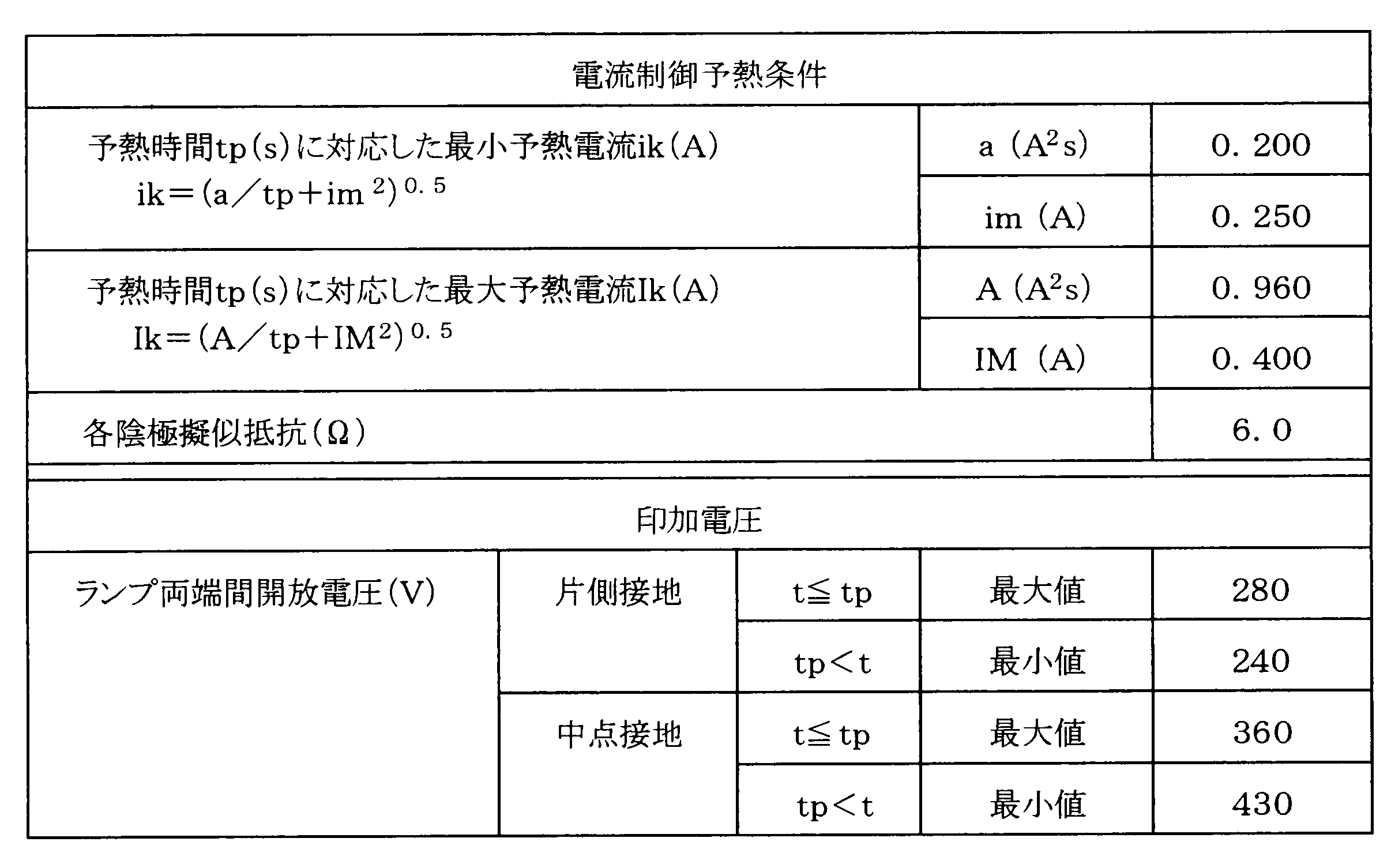
このデータシートより、予熱時間tpを0.5秒とした場合の予熱電流Ifは0.68A以上、1.442A以下が最適な範囲となる。これに対し、図7の回路構成でこの予熱電流を確保しようとする場合の設計例を下記に示す。
共振回路 チョークコイルL1:1.25mH
コンデンサC3:4.7nF
チョッパー回路 出力電圧:400V
インバータ回路 動作周波数 予熱時:77kHz
点灯時:53kHz
共振回路 チョークコイルL1:1.25mH
コンデンサC3:4.7nF
チョッパー回路 出力電圧:400V
インバータ回路 動作周波数 予熱時:77kHz
点灯時:53kHz
以上の条件によれば、点灯装置330よりランプ338に供給される各電気特性は以下の通りとなり、予熱時にランプに印加される電圧がランプの始動に必要な電圧以上となるため、電極が充分に加熱される前にランプが点灯し、電極に大きなダメージが加わる。
予熱電流Ifp:1.09A
予熱時印加電圧Vp:480V
点灯時ランプ電流:0.425A
予熱電流Ifp:1.09A
予熱時印加電圧Vp:480V
点灯時ランプ電流:0.425A
上述したように、予熱時間tpを短くしてランプの電極にダメージを与えずにランプを点灯させるには、ランプに印加される電圧を抑えつつ、電極には充分な予熱電流を流すことが必要である。しかしながら、図7に示した従来例の点灯装置では、設計の制約条件が多く、実現が困難である。
予熱時間を短くするとともにランプに印加される電圧を抑えつつ電極には充分な予熱電流を流せるようにする課題に対しては、図8に示すように、予熱トランスT2を用いて、予熱回路を共振回路と別に設けることにより実現可能である。しかし、この図8に示す回路において、予熱電流を増やすと点灯時においても予熱電流が大きくなり、電極での不要な電力が増大するという課題がある。
このような課題に対して、日本国特開2001-93694号公報(特許文献3)では、センサによる消灯後においても予熱電流を供給しておき、瞬時点灯を可能とした放電灯点灯装置が提案されている。この特許文献3の放電灯点灯装置は、直流電源と、該直流電源の出力を高周波電力に変換するインバータ回路と、インバータ回路の出力に接続される共振回路と、共振回路の共振作用により駆動される放電灯と、インバータ回路の出力を可変とするインバータ制御回路と、外部からの調光信号を入力して放電灯の調光制御と消灯/点灯制御を行う調光制御回路とを備え、放電灯の消灯時には、図9のように、放電灯の電極に少なくとも2つのレベルの予熱電流を所定の周期で切り替えて供給する。
この場合、予熱電流Ifのレベルが高く設定される第1の期間Tbと、予熱電流のレベルが低く設定される第2の期間Taとが交互に切り替わり、第1の期間Tbは第2の期間Taに比べて十分に短く設定されることで、放電灯が点灯しない程度の予熱電流を電極に供給し続ける方法を採っている。これにより瞬時点灯が可能となる。
しかしながら、上記特許文献3に記載の従来例では、瞬時点灯は可能になるものの、待機予熱状態において定常的に電極に電流が流れ、電極で電力が消費されているため、待機予熱状態が長くなると、消費電力が増大するという課題がある。
そこで、上記課題に鑑み、短い予熱時間でより大きな予熱電流を供給可能とする放電灯点灯装置の構成例、及び、ランプ点灯時や待機予熱時において消費電力を低減させ省エネルギーを図ることを可能とする放電灯点灯装置の構成例について、以降の実施形態において例示する。
(第3の実施形態)
本発明の第3の実施形態の具体的構成について図10に示す構成図と図11に示す特性図を用いて詳細に説明する。図10は本発明の第3の実施形態に係る放電灯点灯装置の概略構成を示す図である。図11は第3の実施形態の放電灯点灯装置における負荷回路306の出力電圧Voと、予熱回路305による予熱電流Ifの周波数特性を示した特性図である。
本発明の第3の実施形態の具体的構成について図10に示す構成図と図11に示す特性図を用いて詳細に説明する。図10は本発明の第3の実施形態に係る放電灯点灯装置の概略構成を示す図である。図11は第3の実施形態の放電灯点灯装置における負荷回路306の出力電圧Voと、予熱回路305による予熱電流Ifの周波数特性を示した特性図である。
図10に示す放電灯点灯装置の入力には商用電源301がスイッチ302を介して接続され、出力には熱陰極蛍光ランプであるランプ308が接続される。この放電灯点灯装置は、入力側から整流回路303、インバータ回路304、予熱回路305、及び負荷回路306の順に構成され、負荷となるランプ308に接続される。
放電灯点灯装置において、まず、整流回路303は、商用電源301から入力される交流電源ACを全波整流するブリッジ構成のダイオードD1~D4と、直流電源に接続されるとともに少なくとも一つのスイッチング素子Q3を有し、直流電源からの直流電圧を所定の直流電圧に変換するチョッパ回路と、例えばアルミ電解コンデンサ等の比較的大容量のコンデンサC2とを含んで構成される。この整流回路303は、商用電源301の交流電圧を全波整流し、略一定の直流電圧に平滑する。入力の交流電源ACは、商用の交流電源であり、電圧は、例えば、100V、200Vまたは240Vである。
以下、整流回路303の各部の構成を詳述する。ダイオードD1~D4は、交流電源ACからの交流電圧を脈流電圧に整流し出力するものである。また、チョッパ回路は、昇圧式のAC-DCコンバータであり、整流回路303によって全波整流された電源電圧を所定の直流電圧に昇圧して出力する。チョッパ回路の構成は、チョークコイルL2とダイオードD5が直列に整流回路303のダイオードブリッジD1~D4の出力段の一端と平滑用コンデンサC2との間に挿入されており、チョークコイルL2とダイオードD5の接続点とダイオードブリッジD1~D4出力段のもう一端の間には、MOSFET等のスイッチング素子Q3が接続されている。
スイッチング素子Q3を導通させると、ダイオードブリッジD1~D4の出力段からチョークコイルL2とスイッチング素子Q3を介して電流が流れることにより、チョークコイルL2にはエネルギーが蓄えられる。次に、スイッチング素子Q3を遮断すると、チョークコイルL2に蓄えられたエネルギーはダイオードD5を介してコンデンサC2へと供給される。このようにスイッチング素子Q3の導通と遮断を繰り返すことにより、コンデンサC2への電流供給と遮断を繰り返し、このスイッチングを高周波で行うことによりコンデンサC2の両端にはほぼ直流の電圧を得ることができる。
また、フィルタT1とダイオードブリッジD1~D4の間にはチョークコイルL3が挿入されており、ダイオードブリッジD1~D4の出力段にはコンデンサC8が並列に挿入されている。このチョークコイルL3とコンデンサC8によってフィルタ回路が構成されており、チョッパ回路のスイッチングによって発生する高周波電流をコンデンサC8を介してバイパスさせることにより、高周波電流が商用電源301側に流れることがないようにしている。
ここでは昇圧式のチョッパ回路について説明しているが、降圧式や昇降圧式といった他のチョッパ回路でもよく、商用電源301の交流電圧を直流電圧に変換できる構成であれば、その作用効果は変わらない。
次に、インバータ回路304について詳述する。インバータ回路304は、整流回路303の出力段に接続され、MOSFET等のスイッチング素子を2個直列に接続した構成となっている。この2つのスイッチング素子Q1、Q2を50kHz程度の高周波で交互にスイッチングすることにより、スイッチング素子の両端には高周波の矩形波電圧が発生するため、整流回路303により平滑された直流電圧を高周波電圧に変換することができる。
インバータ回路として、本実施形態では、いわゆるハーフブリッジ型のインバータ回路を採用している。もちろんインバータ回路は、その他フルブリッジ型、1石型、あるいはプッシュプル型であってもよい。
次に、予熱回路305について詳述する。予熱回路305は、トランスT2を有して構成され、トランスT2の1次側巻線n1の一端は直流カット用のコンデンサC5を介してインバータ回路304の出力段に接続されている。また、トランスT2の2次側にはランプ308の2つの電極をそれぞれ別個に加熱できるように巻線n2、n3が設けられており、それぞれの電極にコンデンサC6、C7を介して接続されている。また、コンデンサC9及びMOSFET等のスイッチング素子Q4が設けられ、トランスT2の1次側巻線n1の他端とインバータ回路304の出力段との間に並列に接続されている。このスイッチング素子Q4のON/OFFにより、所定の予熱電流を供給する制御を行っている。
スイッチング素子Q4がONの時には、トランスT2によって二次側に発生する電圧を電源としてランプの各電極を予熱するものである。コンデンサC6、C7は、各フィラメントの予熱電流Ifの減流インピーダンスとして機能する。スイッチング素子Q4がOFFの時には、矩形波の殆どの電圧をコンデンサC9が保持するため、トランスT2の二次側には殆ど電圧が発生しない。そのため、ランプの各電極を予熱する電流を抑えることができる。
このような予熱回路305を構成することで、(スイッチング素子Q4がON時の電流供給量)>(スイッチング素子Q4がOFF時の電流供給量)となり、スイッチング素子Q4により予熱電流の供給量を制御することができる。以降では、スイッチング素子Q4がOFF時の電流を第1の予熱電流Ifp1、スイッチング素子Q4がON時の電流を第2の予熱電流Ifp2とする。
負荷回路306は、インバータ回路304のスイッチング素子Q2と並列にチョークコイルL1、共振コンデンサC3、及び直流カット用コンデンサC4が直列に接続されて構成される。この負荷回路306は、インバータ回路304の矩形波電圧を正弦波状の電圧に変換してランプ308に供給する。
以下、本実施形態の要部となっている、制御回路307について詳述する。制御回路307は、チョッパ制御回路371、インバータ制御回路(インバータ制御部)372、予熱制御回路(予熱制御部)373、タイマ回路(タイマ部)374、消灯制御部310を有して構成される。
チョッパ制御回路371は、スイッチング素子Q3のスイッチングを制御するもので、コンデンサC2の両端電圧を抵抗R1とR2で分圧して検出している。コンデンサC2の両端電圧が所定の電圧よりも低い場合にはスイッチング素子Q2の導通時間が長くなるように、逆にコンデンサC2の両端電圧が低い場合には導通時間が短くなるようにフィードバック制御する。これにより、電源電圧や負荷の状態が変化してもコンデンサC2の電圧を一定に制御することができる。
インバータ制御回路372は、インバータ回路304の動作周波数を変化させることにより、負荷回路306のインピーダンスが周波数によって変化することを利用して、ランプ308への供給電力を制御する。このインバータ制御回路372には、インバータ回路304の動作開始からの時間を計測するタイマ回路374が接続されており、タイマ回路374の計測時間に基づいてランプ308の電極を加熱する予熱時間とランプ308の電極間に高電圧Vsを印加するタイミングを制御することにより、ランプ308を確実に点灯させることができる。
予熱制御回路373は、予熱回路305のスイッチング素子Q4のON/OFFを制御するもので、タイマ回路374でランプ308の電極を加熱する予熱時間を計測し、この計測時間に基づいて予熱回路305のスイッチング素子Q4のON/OFFのタイミングを制御することにより、第1の予熱電流、第2の予熱電流の2段階に予熱電流を自由に切り替え、電極に流れる予熱電流の供給を制御することができる。
消灯制御回路310は、消灯信号及び点灯信号を出力し、タイマ回路374に送信するものである。消灯制御回路310は、センサ等の外部信号309に対して、人がいない時には消灯信号を送信し、人を検知した場合は点灯信号をタイマ回路374に送信する。
図12は第3の実施形態の放電灯点灯装置における消灯信号と点灯信号を示す動作説明図である。消灯制御回路310は、例えば、図12に示すように消灯信号として時間t0~t1には0Vを送信し、点灯信号として時間t1~には5Vを送信する制御を行う。ここで、消灯制御回路310は、外部信号309として人を検出するセンサ等の出力を用いて、人がいない時には消灯する等の制御を行うものとしているが、PWM信号のデューティ制御を行うものや、DC電圧を制御するもの、デジタル信号を制御するものであっても構わない。
本実施形態の放電灯点灯装置は、上記のような回路構成とすることにより、予熱時間中(ランプ308が点灯していない状態)の出力電圧Voと予熱電流Ifは、図11に示すような周波数特性となる。ここで、周波数のf0は負荷回路306の固有振動周波数であり、図10の回路構成の場合には次式で示すことができる。

インバータ制御回路372は、インバータ回路304の動作周波数を変化させることで、インバータ回路304の動作周波数をこのf0に近付けると負荷回路306の出力電圧Voを高くすることができ、f0から遠ざけると出力電圧Voを低くすることができる。
本実施形態では、予熱回路305のスイッチング素子Q4をON/OFFすることにより、スイッチング素子Q4がONの時には、第2の予熱電流Ifp2が供給される。また、スイッチング素子Q4がOFFの時には、スイッチング素子Q4に並列に接続されたコンデンサC9により予熱電流が保持され、第2の予熱電流Ifp2よりも小さい第1の予熱電流Ifp1が供給される。
ここで、負荷回路306の固有振動周波数f0とインバータ回路304の動作周波数との関係は、予熱電流供給時は、図11に示すように動作周波数をf0よりも高いfpに設定する。そして、インバータ制御回路372は、タイマ回路374によってインバータ回路304の動作時間が予熱時間を経過したことを確認した後、動作周波数をfpからf0の近傍のfsに移行させランプを点灯させる。このように設定することにより、所定の予熱時間中はランプ308の電極を最適に加熱し、かつそのときの電極間に印加される電圧Vpをランプ308が放電を開始しないレベルに下げることができ、予熱時間経過後にランプ308の電極間に高電圧Vsを印加し、ランプ308の電極にダメージを与えずに、かつ確実にランプを点灯させることができる。したがって、ランプ308の点灯回数が増えてもランプ308の寿命が短くなることを回避することができる。
以上のように、放電灯点灯回路を構成することで図13に示すような動作波形に制御することができる。図13は第3の実施形態の放電灯点灯装置における負荷回路306の予熱電流Ifと出力電圧Vlaの波形を示す図であり、消灯後の再点灯時の動作波形を示したものである。まず、時間t0にセンサ等の外部信号309に基づき消灯制御部310が消灯信号をタイマ回路374に送信し、消灯が指示された場合、インバータ制御回路372はタイマ回路374を介して消灯信号を受け、インバータ回路304を停止させランプ308を消灯させる。この際、予熱電流Ifと出力電圧Vlaは0になる。
そして、時間t1でセンサ等の外部信号309に基づき消灯制御部310が点灯信号を送信し、消灯後の再点灯が指示された場合、インバータ制御回路372はタイマ回路374を介して点灯信号を受け、ますインバータ回路304の動作周波数をfpに移行して動作させ、予熱制御回路373により予熱回路305のスイッチング素子Q4をONに切り替えて、再点灯時予熱電流として第2の予熱電流Ifp2を供給してランプ308の電極を予熱する。この予熱時間中は、電極間に印加される電圧Vpはランプ308が放電を開始しない小さい電圧となっている。その後、予熱時間経過後にインバータ回路304の動作周波数をfpからfsに移行し、ランプ308の電極間に高電圧Vsを印加し、ランプ308を再点灯させる。ここで、再点灯時に第2の予熱電流Ifp2を供給する予熱時間は、0.5秒以下とする。
前記課題でも述べたように、センサ等の外部信号309から消灯信号を受けた後の再点灯には、できるだけ瞬時点灯が好ましい。図11及び図13に示したように、第2の予熱電流Ifp2は第1の予熱電流Ifp1よりも大きい予熱電流となっているため、再点灯時には第2の予熱電流Ifp2のみで点灯させるように設定することで、再点灯時での瞬時点灯が可能となる。
なお、本実施形態では、予熱電流を2段階に切り替える場合についてのみ説明しているが、予熱電流を3以上の複数段階に設定してもよい。以降の実施形態においても同様である。
(第4の実施形態)
以降の実施形態では、基本的な回路構成は図10に示したものと同様であるため、詳細な回路説明は省略する。
以降の実施形態では、基本的な回路構成は図10に示したものと同様であるため、詳細な回路説明は省略する。
本発明の第4の実施形態の動作波形を図14に示す。図14は第4の実施形態の放電灯点灯装置における予熱電流Ifと出力電圧Vlaの波形を示す図であり、消灯時の動作波形を示したものである。
図14に示すように、タイマ回路374がセンサ等の外部信号309から消灯信号を受け、消灯が指示された場合、インバータ制御回路372はインバータ回路304の動作周波数をfpに移行し、ランプ308を消灯させるとともに、予熱制御回路373により予熱回路305のスイッチング素子Q4をOFFさせ、消灯時予熱電流としてより少ない第1の予熱電流Ifp1を供給してランプ308の電極を予熱する。このように消灯時は、予熱電流Ifp1の供給を継続させることで、消費電力を低減させて省エネルギーを図ることができる。また、再点灯する場合に点灯までの時間を短くすることができる。ただし、第3の実施形態でも述べたように、この時の電極間に印加される電圧Vpは、ランプ308が放電を開始しないレベルに小さく設定する必要がある。
(第5の実施形態)
本発明の第5の実施形態の動作波形を図15に示す。図15は第5の実施形態の放電灯点灯装置における予熱電流Ifと出力電圧Vlaの波形を示す図であり、消灯時の動作波形を示したものである。第4の実施形態と同様、タイマ回路374がセンサ等の外部信号309から消灯信号を受け、消灯が指示された場合、インバータ制御回路372は、ランプ308を消灯させるとともに、第1の予熱電流Ifp1により予熱電流の供給を継続させる。
本発明の第5の実施形態の動作波形を図15に示す。図15は第5の実施形態の放電灯点灯装置における予熱電流Ifと出力電圧Vlaの波形を示す図であり、消灯時の動作波形を示したものである。第4の実施形態と同様、タイマ回路374がセンサ等の外部信号309から消灯信号を受け、消灯が指示された場合、インバータ制御回路372は、ランプ308を消灯させるとともに、第1の予熱電流Ifp1により予熱電流の供給を継続させる。
そして、第5の実施形態では、タイマ回路374には一定値である所定の時間T3(予熱停止時間)が記憶されており、この予熱停止時間T3と計測された予熱時間とを比較し、予熱時間が予熱停止時間T3を越えると、インバータ制御回路372はインバータ回路304を停止させ、放電灯点灯装置を停止させる。所定の予熱停止時間T3は、例えば消費電力の増大を抑えるためには、約1分程度に設定する。ただし、予熱停止時間T3を越える前に、再点灯が指示された場合は、第3の実施形態と同様に予熱制御回路373によりスイッチング素子Q4をONさせ、第2の予熱電流Ifp2でランプ308の電極を予熱して再点灯させる。このように予熱停止時間経過後に予熱電流Ifp1の供給を停止することで、消費電力の増大を抑えることができる。
(第6の実施形態)
本発明の第6の実施形態の構成を図16に、動作波形を図17に示す。図16は本発明の第6の実施形態に係る放電灯点灯装置の概略構成を示す図、図17は第6の実施形態の放電灯点灯装置における予熱電流Ifと出力電圧Vlaの波形を示す図であり、電源ON時の動作波形を示したものである。
本発明の第6の実施形態の構成を図16に、動作波形を図17に示す。図16は本発明の第6の実施形態に係る放電灯点灯装置の概略構成を示す図、図17は第6の実施形態の放電灯点灯装置における予熱電流Ifと出力電圧Vlaの波形を示す図であり、電源ON時の動作波形を示したものである。
第6の実施形態は、図10に示した第3の実施形態の構成に加えて、タイマ回路374に予熱時間比較部381、インバータ動作時間比較部382を設けている。その他の構成は図10と同様である。
タイマ回路374には、図17に示すように、一定値である所定の時間T1(第1の点灯時予熱時間)及びT2(第2の点灯時予熱時間)が記憶されており、予熱時間比較部381によりこれらの第1の点灯時予熱時間T1及び第2の点灯時予熱時間T2と計測された予熱時間とを比較する。電源投入時は、予熱時間比較部381により第1の点灯時予熱時間T1と計測された予熱時間とを比較し、予熱時間が第1の点灯時予熱時間T1を越えるまで、予熱制御回路373は予熱回路305のスイッチング素子Q4をOFFさせ、第1の点灯時予熱電流として第1の予熱電流Ifp1をランプ308の電極に供給して予熱する。予熱時間が第1の点灯時予熱時間T1を越えると、予熱制御回路373はスイッチング素子Q4をONさせ、第2の点灯時予熱電流として第2の予熱電流Ifp2に切り替えてランプ308の電極に供給する。そして、予熱時間比較部381により第2の点灯時予熱時間T2と計測された予熱時間とを比較し、第2の点灯時予熱時間T2を越えるまで、予熱制御回路373は第2の点灯時予熱電流として第2の予熱電流Ifp2を供給し、ランプ308を予熱する。
また、インバータ動作時間比較部382により、第1の点灯時予熱時間T1及び第2の点灯時予熱時間T2と計測されたインバータ回路の動作時間とを比較する。インバータ制御回路372は、インバータ動作時間比較部382の比較により第1の点灯時予熱時間T1及び第2の点灯時予熱時間T2が経過するまでは、インバータ回路304の動作周波数をfpにして動作させる。そして、第1の点灯時予熱時間T1及び第2の点灯時予熱時間T2の終了後は、インバータ回路304の動作周波数をfsに移行し、ランプ308の電極間に高電圧Vsを印加し、ランプ308を始動させる。
このように、第6の実施形態によれば、電源投入時にのみ所定の第1の点灯時予熱時間T1の期間は第1の予熱電流Ifp1を供給して、電極をある程度予熱するようにし、その後第2の点灯時予熱時間T2の期間は第2の予熱電流Ifp2を供給し、電源投入時に予熱電流を段階的に大きくすることで、ランプが短寿命になるという問題を回避することができる。ここで、第1の予熱電流Ifp1は0であっても構わない。また、第1の予熱電流Ifp1を供給する第1の点灯時予熱時間T1及び第2の予熱電流Ifp2を供給する第2の点灯時予熱時間T2は、使用者にとって不快なものとならない程度に設定する必要がある。例えば、電源投入時の場合には第1及び第2の点灯時予熱時間T1、T2を合わせて約2秒以下に設定することが望ましい。
(第7の実施形態)
本発明の第7の実施形態の動作波形を図18及び図19に示す。図18は第7の実施形態の放電灯点灯装置における電源ON時の予熱電流Ifと出力電圧Vlaの波形を示す図、図19は第7の実施形態の放電灯点灯装置における消灯から再点灯時の予熱電流Ifと出力電圧Vlaの波形を示す図である。
本発明の第7の実施形態の動作波形を図18及び図19に示す。図18は第7の実施形態の放電灯点灯装置における電源ON時の予熱電流Ifと出力電圧Vlaの波形を示す図、図19は第7の実施形態の放電灯点灯装置における消灯から再点灯時の予熱電流Ifと出力電圧Vlaの波形を示す図である。
図18のように、電源投入直後から予熱→始動→点灯と移行する場合、インバータ制御回路372は、タイマ回路374にて計時された時間に基づき、インバータ回路304の動作周波数を、予熱時fp→始動時fs→点灯時fpとなるように切り替える。そして、点灯時のインバータ動作周波数fpの時には、予熱制御回路373は予熱回路305のスイッチング素子Q4をOFFさせ、点灯中予熱電流として第1の予熱電流Ifp1を供給する。
また、図19のように、消灯信号の後に点灯信号を受けて再点灯する場合、上記点灯時と同様に、予熱制御回路373は予熱回路305のスイッチング素子Q4をOFFさせ、点灯中予熱電流として第1の予熱電流Ifp1を供給する。
このように第7の実施形態では、点灯中において、第2の予熱電流Ifp2よりも小さい第1の予熱電流Ifp1にて予熱電流を供給することで、点灯中の消費電力も低減させることができる。
(第8の実施形態)
本発明の第8の実施形態の構成を図20に、動作のフローチャートを図21及び図22に示す。図20は本発明の第8の実施形態に係る放電灯点灯装置の概略構成を示す図、図21は第8の実施形態の放電灯点灯装置の動作の第1例を説明するためのフローチャート、図22は第8の実施形態の放電灯点灯装置の動作の第2例を説明するためのフローチャートである。
本発明の第8の実施形態の構成を図20に、動作のフローチャートを図21及び図22に示す。図20は本発明の第8の実施形態に係る放電灯点灯装置の概略構成を示す図、図21は第8の実施形態の放電灯点灯装置の動作の第1例を説明するためのフローチャート、図22は第8の実施形態の放電灯点灯装置の動作の第2例を説明するためのフローチャートである。
第8の実施形態は、図10に示した第3の実施形態の構成に加えて、タイマ回路374に回数カウンタ部383、不揮発性メモリ361を設け、不揮発性メモリ361に記憶された累積回数をリセットするリセット制御部362を設けている。その他の構成は図10と同様である。
回数カウンタ部383は、センサ等の外部信号309からの消灯信号、もしくは第2の予熱電流Ifp2の動作回数をカウントする。不揮発性メモリ361は、このカウントした消灯信号の回数、もしくは第2の予熱電流Ifp2の動作回数を逐次記憶する。制御回路307は、この回数に応じて、少なくとも第2の予熱電流Ifp2を供給する第2の点灯時予熱時間T2、もしくは第2の予熱電流Ifp2の供給量を自由に変化させることが可能になっている。
リセット制御部362は、ランプ308を新品に交換した場合などに、不揮発性メモリ361に記憶された累積回数を初期値(累積回数が零の状態)にリセットする動作を行う。リセット動作として、具体的には、リセットボタンの操作によるリセット方法や、ランプ308の寿命末期状態を検出して自動的にリセットする方法、電源の既定のオン・オフ操作によってリセットする方法などが挙げられる。通常、不揮発性メモリ361としては、汎用のEEPROMやマイクロプロセッサに内蔵されたフラッシュメモリ等の不揮発性メモリにより構成することができる。
次に、図21及び図22を参照して第8の実施形態の動作を詳細に説明する。まず、図21に示す第1例は、第2の予熱電流の動作回数のみを用いる例である。この第1例では、電源ONしたときに(ステップS311)、予熱制御回路373が予熱回路305のスイッチング素子Q4をOFFし、第1の予熱電流Ifp1を供給する(ステップS312)。そして、第1の点灯時予熱時間T1が経過するかを判定し(ステップS313)、時間T1が経過すると(ステップS313:Y)、予熱制御回路373がスイッチング素子Q4をONし、第2の予熱電流Ifp2を供給する(ステップS314)。その後、第2の点灯時予熱時間T2が経過するかを判定し(ステップS315)、時間T2が経過すると(ステップS315:Y)、回数カウンタ部383が第2の予熱電流Ifp2が動作した回数を計測し(ステップS316)、この動作回数を不揮発性メモリ361に記憶する(ステップS317)。このとき、タイマ回路374は、例えば表3に示すように、第2の予熱電流の動作回数に応じて第2の予熱電流時間T2を変化させることができる。

このように回数カウンタ部383でカウントし不揮発性メモリ361に記憶した第2の予熱電流の動作回数が増えるにつれて、第2の予熱電流時間T2の時間を長くする。これにより、電極を予熱する時間が長くなるため、ランプが短寿命になるという問題を回避することができる。
そして、インバータ制御回路372は、ランプ308の電極間に高電圧Vsを印加し、ランプ308を点灯させる(ステップS318)。このとき、予熱時間中はインバータ回路304の動作周波数をfpとし、予熱時間経過後はインバータ回路304の動作周波数をfpからfsに移行し、ランプ308を点灯させる。
ランプ点灯時は、予熱制御回路373がスイッチング素子Q4をOFFし、第1の予熱電流Ifp1を供給する(ステップS319)。その後、消灯制御部310において外部信号が点灯信号か消灯信号かを判断し(ステップS320)、外部信号が消灯信号の場合(ステップS320:N)、インバータ制御回路372がインバータ回路304を制御してランプを消灯する(ステップS321)。
そして、予熱停止時間T3が経過するかを判定し(ステップS322)、時間T3が経過すると(ステップS322:Y)、予熱制御回路373が第1の予熱電流Ifp1の供給を停止する(ステップS323)。一方、時間T3が経過していない場合(ステップS322:N)、予熱制御回路373が第1の予熱電流Ifp1の供給を継続する(ステップS324)。その後、消灯制御部310において外部信号が点灯信号か消灯信号かを判断し(ステップS325)、外部信号が点灯信号の場合(ステップS325:Y)、ステップS314に戻って第2の予熱電流Ifp2の供給を行う。一方、外部信号が消灯信号の場合(ステップS325:N)、ステップS321に戻りランプを消灯する。
また、図22に示す第2例は、図21の第1例の変形例であり、第2の予熱電流の動作回数とともに消灯信号の回数を用いる例である。ここでは図21と異なる部分についてのみ説明する。この第2例では、ステップS320で外部信号が消灯信号の場合、回数カウンタ部383は消灯信号が入力された回数を計測し(ステップS331)、この回数を不揮発性メモリ361に記憶する(ステップS332)。このとき、タイマ回路374は、例えば表4に示すように、消灯信号の回数に応じて第2の予熱電流時間T2を変化させることができる。
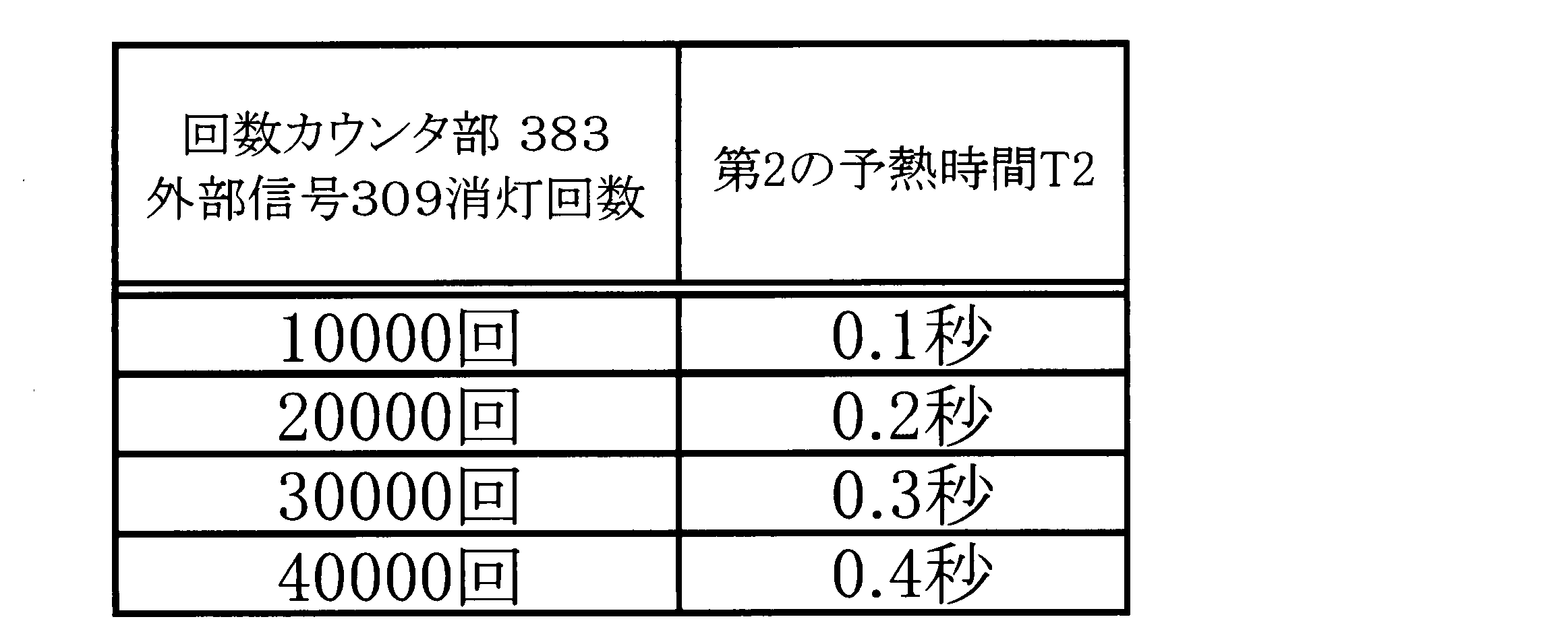
このように回数カウンタ部383でカウントし不揮発性メモリ361に記憶した消灯信号の回数が増えるにつれて、第2の予熱電流時間T2の時間を長くする。これにより、電極を予熱する時間が長くなるため、ランプが短寿命になるという問題を回避することができる。
上記のように、本実施形態では、第2の予熱電流の動作回数や消灯信号の回数によって第2の予熱時間T2を変化させることが可能であるが、さらに、図11に示したように、インバータ回路304の動作周波数を変化させることで、第2の予熱電流Ifp2の供給量も同様に自由に変化させることができる。例えば、第2の予熱電流の動作回数もしくは消灯信号の回数を不揮発性メモリ361で記憶し、この回数が多くなるにつれて、インバータ回路304の動作周波数fpを徐々に高い周波数に移行することで、第2の予熱電流Ifp2の供給量も大きくすることが可能である。このように設定することで、同様にランプの寿命が短くなることを防止できる効果を得ることができる。
(第9の実施形態)
本発明の第9の実施形態の構成を図23に、動作のフローチャートを図24に示す。図23は本発明の第9の実施形態に係る放電灯点灯装置の概略構成を示す図、図24は第9の実施形態の放電灯点灯装置の動作を説明するためのフローチャートである。
本発明の第9の実施形態の構成を図23に、動作のフローチャートを図24に示す。図23は本発明の第9の実施形態に係る放電灯点灯装置の概略構成を示す図、図24は第9の実施形態の放電灯点灯装置の動作を説明するためのフローチャートである。
第9の実施形態は、図20に示した第8の実施形態の変形例であり、タイマ回路374において、回数カウンタ部383の代わりに時間カウンタ部384を設けたものである。その他の構成は図20と同様である。
時間カウンタ部384は、整流回路303の出力に基づき、放電灯の点灯時間をカウントする。ここで、点灯時間は、タイマ回路374の時間カウンタ部384が整流回路303からの直流電圧を受けることでカウントを開始する。なお、センサ等の外部信号309による点灯信号、消灯信号に基づく点灯時間をカウントしてもよい。不揮発性メモリ361は、このカウントした放電灯の点灯時間を累積点灯時間として逐次記憶する。
次に、図24を参照して第9の実施形態の動作を詳細に説明する。ここでは、図21及び図22に示した第8の実施形態と異なる部分についてのみ説明する。
ステップS318でランプを点灯させ、ステップS319で第1の予熱電流Ifp1を供給した状態で、時間カウンタ部384がランプの点灯時間を計測し(ステップS341)、この点灯時間を不揮発性メモリ361に記憶する(ステップS342)。このとき、タイマ回路374は、例えば表5に示すように、ランプの点灯時間に応じて第2の予熱電流時間T2を変化させることができる。
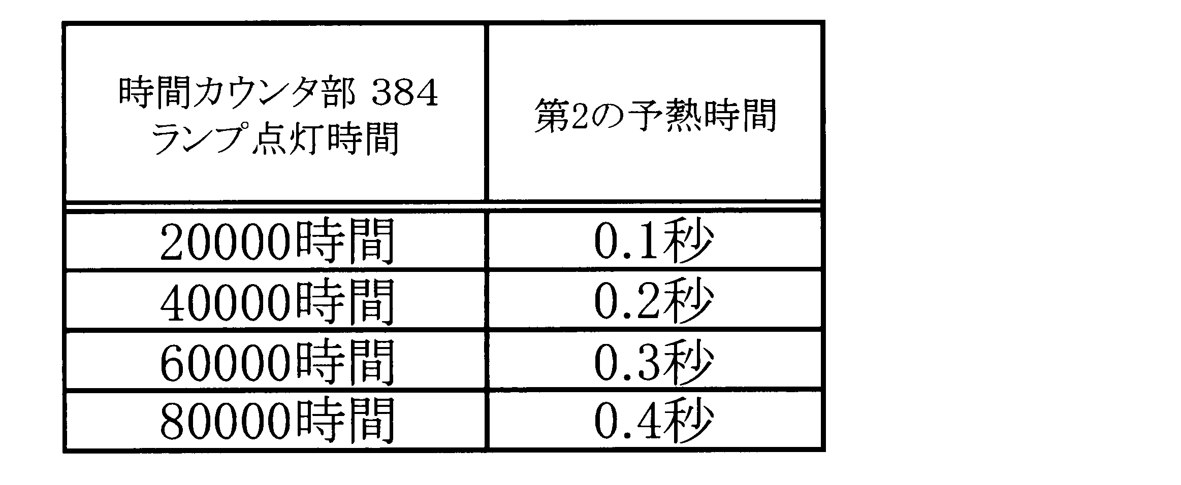
このように時間カウンタ部384でカウントし不揮発性メモリ361に記憶した累積点灯時間が長くなるにつれて、第2の予熱電流時間T2の時間を長くする。これにより、電極を予熱する時間が長くなるため、ランプが短寿命になるという問題を回避することができる。
その後、消灯制御部310において外部信号が点灯信号か消灯信号かを判断し(ステップS343)、外部信号が消灯信号の場合(ステップS343:N)、時間カウンタ部384はランプの点灯時間の計測を終了し(ステップS344)、不揮発性メモリ361は累積点灯時間の記憶を終了する(ステップS345)。そして、ステップS321でインバータ制御回路372がインバータ回路304を制御してランプを消灯する。
さらに、累積点灯時間によって、第8の実施形態と同様に、インバータ回路304の動作周波数を変化させることで、第2の予熱電流Ifp2の供給量も同様に自由に変化させることができる。例えば、累積点灯時間を不揮発性メモリ361で記憶し、この時間が多くなるにつれて、インバータ回路304の動作周波数fpを徐々に高い周波数に移行することで、第2の予熱電流Ifp2の供給量も大きくすることが可能である。このように設定することで、同様にランプの寿命が短くなることを防止できる効果を得ることができる。
このように第9の実施形態では、ランプの累積点灯時間に応じて、少なくとも第2の予熱電流Ifp2を供給する予熱時間T2、もしくは第2の予熱電流Ifp2の供給量を自由に変化させることができ、ランプ寿命の短縮を防止することができる。
上記第3~第9の実施形態において、制御回路307のチョッパ制御回路371、インバータ制御回路372、予熱制御回路373、タイマ回路374、消灯制御部310等の各構成要素は、マイクロコンピュータを用いて容易に構成することができ、プロセッサとこのプロセッサ上で動作するプログラムによって、各動作に対応する処理を実行することで、上記実施形態の各機能を実現することが可能である。
以上のように、本実施形態の放電灯点灯装置では、電極に供給する予熱電流を2段階以上に切り替え可能であり、少なくともセンサ信号に基づき消灯させた後にランプを再点灯させる際には、短い予熱時間で、より大きな予熱電流を供給させることができる。また、ランプ点灯時や待機予熱時には、より少ない予熱電流を供給することにより、消費電力を低減させて省エネルギーを図ることが可能となる。
なお、本発明は上記の実施形態において示されたものに限定されるものではなく、明細書の記載、並びに周知の技術に基づいて、当業者が変更、応用することも本発明の予定するところであり、保護を求める範囲に含まれる。
本出願は、2008年6月20日出願の日本特許出願(特願2008-161900)、2008年8月26日出願の日本特許出願(特願2008-216290)に基づくものであり、その内容はここに参照として取り込まれる。
1、2 照明システム
11、21 照明点灯装置
12、22 外部機器
13 放電灯
119、219 入力信号処理部
120、220 外部機器判別部
121、221 人体検知センサ
122、222 照度センサ
123、223 調光器
301 商用電源
302 スイッチ
303 整流回路
304 インバータ回路
305 予熱回路
306 負荷回路
307 制御回路
308 ランプ
309 外部信号
310 消灯制御部
361 不揮発性メモリ
362 リセット制御部
371 チョッパ制御回路
372 インバータ制御回路
373 予熱制御回路
374 タイマ回路
381 予熱時間比較部
382 インバータ動作時間比較部
383 回数カウンタ部
384 時間カウンタ部
11、21 照明点灯装置
12、22 外部機器
13 放電灯
119、219 入力信号処理部
120、220 外部機器判別部
121、221 人体検知センサ
122、222 照度センサ
123、223 調光器
301 商用電源
302 スイッチ
303 整流回路
304 インバータ回路
305 予熱回路
306 負荷回路
307 制御回路
308 ランプ
309 外部信号
310 消灯制御部
361 不揮発性メモリ
362 リセット制御部
371 チョッパ制御回路
372 インバータ制御回路
373 予熱制御回路
374 タイマ回路
381 予熱時間比較部
382 インバータ動作時間比較部
383 回数カウンタ部
384 時間カウンタ部
Claims (14)
- 外部機器として、人の存否を検知する人体検知センサと、空間の照度を検出する照度センサと、前記空間の照度を任意に調整する調光器のいずれかが接続され、前記外部機器から出力される信号に基づいて、光源の光出力を制御するための出力制御信号を生成する照明点灯装置であって、
前記外部機器から出力される信号に基づいて、接続された前記外部機器の種類を判別する外部機器判別部と、
前記外部機器から出力される信号に基づいて、前記出力制御信号を生成する信号処理部と、を具備した照明点灯装置。 - 請求項1に記載の照明点灯装置であって、
前記外部機器から出力される信号は、
前記外部機器それぞれに特有の外部機器判別信号と、
前記光源の点灯動作を制御するための、前記外部機器それぞれに特有の点灯動作制御信号と、からなり、
前記外部機器判別部は、
前記外部機器判別信号から、接続された前記外部機器の種類を判別して、前記信号処理部に通知し、
前記信号処理部は、
通知された前記外部機器の種類に対応して、前記点灯動作制御信号から前記出力制御信号を生成する照明点灯装置。 - 請求項1に記載の照明点灯装置であって、
前記外部機器から出力される信号は、
前記点灯動作制御信号からなり、
前記外部機器判別部は、
前記点灯動作制御信号から、接続された前記外部機器の種類を判別して、前記信号処理部に通知し、
前記信号処理部は、
通知された前記外部機器の種類に対応して、前記点灯動作制御信号から前記出力制御信号を生成する照明点灯装置。 - 請求項3に記載の照明点灯装置であって、
前記人体検知センサから出力される前記点灯動作制御信号の信号形態は、
前記人の存否に応じて、前記光源を点灯、或いは消灯するための2値信号であり、
前記照度センサから出力される前記点灯動作制御信号の信号形態は、
前記空間の照度に応じて変化し、前記光源の出力を制御して前記空間の照度を一定にするための直流電圧であり、
前記調光器から出力される前記点灯動作制御信号の信号形態は、
デューティ比を変化させることによって前記光源の出力を制御し、前記空間の照度を所望の値に制御するための周波数が一定のPWM信号であり、
前記外部機器判別部は、
前記点灯動作制御信号が前記いずれの信号形態であるかによって、前記外部機器の種類を判別する照明点灯装置。 - 光源は放電灯である請求項1から4のいずれかに記載の照明点灯装置であって、
前記放電灯の電極に予熱電流を供給するもので、この予熱電流の供給量を少なくとも第1の予熱電流と第2の予熱電流を持つ複数段階に切り替え可能な予熱回路と、
前記予熱回路に予熱電流を供給する予熱時間を設定するタイマ部と、
前記予熱回路から出力する予熱電流の供給量を切り替える予熱制御部と、を備えており、
前記予熱制御部は、放電灯消灯後の再点灯時に、点灯時の第1の予熱電流よりも大きい第2の予熱電流を再点灯時予熱電流として供給するよう前記予熱回路を切り替える照明点灯装置。 - 請求項5に記載の照明点灯装置であって、
前記予熱制御部は、放電灯消灯時に、前記第2の予熱電流よりも小さい第1の予熱電流を消灯時予熱電流として供給するよう前記予熱回路を切り替える照明点灯装置。 - 請求項6に記載の照明点灯装置であって、
前記タイマ部は、前記予熱電流の供給を停止する予熱停止時間を設定し、
前記予熱制御部は、前記放電灯消灯時に前記予熱停止時間が経過した後、前記予熱回路からの消灯時予熱電流の供給を停止する照明点灯装置。 - 請求項5に記載の照明点灯装置であって、
前記タイマ部は、前記予熱時間として第1の点灯時予熱時間と第2の点灯時予熱時間とを設定し、
前記予熱制御部は、電源投入時に前記第1の点灯時予熱時間が経過するまでは第1の点灯時予熱電流として第1の予熱電流を供給し、前記第1の点灯時予熱時間の経過後から前記第2の点灯時予熱時間が経過するまでは第2の点灯時予熱電流として前記第1の予熱電流よりも大きい第2の予熱電流を供給するよう前記予熱回路を切り替える照明点灯装置。 - 請求項5に記載の照明点灯装置であって、
前記予熱制御部は、放電灯点灯後に、前記第2の予熱電流よりも小さい第1の予熱電流を点灯中予熱電流として供給するよう前記予熱回路を切り替える照明点灯装置。 - 請求項5に記載の照明点灯装置であって、
前記タイマ部は、前記放電灯消灯後の再点灯時に前記再点灯時予熱電流を供給する時間を0.5秒以下に設定する照明点灯装置。 - 請求項5から10のいずれかに記載の照明点灯装置であって、
前記タイマ部は、前記第2の予熱電流を供給する動作回数または前記外部信号による消灯信号の回数をカウントする回数カウンタ部を有し、
前記回数に応じて、前記第2の予熱電流を供給する供給時間と前記第2の予熱電流の大きさとの少なくとも一方を変化させる照明点灯装置。 - 請求項5から10のいずれかに記載の照明点灯装置であって、
前記タイマ部は、前記放電灯の点灯時間をカウントする時間カウンタ部を有し、
前記点灯時間に応じて、前記第2の予熱電流を供給する供給時間と前記第2の予熱電流の大きさとの少なくとも一方を変化させる照明点灯装置。 - 請求項1乃至12のいずれかに記載の照明点灯装置と、
前記照明点灯装置から電力が供給されることによって点灯する前記光源と、
を有してなる照明器具。 - 請求項13に記載の前記照明器具と、
前記照明器具に接続された外部機器と、
を有してなる照明システム。
Priority Applications (3)
| Application Number | Priority Date | Filing Date | Title |
|---|---|---|---|
| US12/999,737 US8648544B2 (en) | 2008-06-20 | 2009-06-15 | Illumination lighting apparatus, illumination apparatus, and illumination system |
| EP09766628.3A EP2296448B1 (en) | 2008-06-20 | 2009-06-15 | Illumination lighting device, illuminating device, and illuminating system |
| CN200980123205.6A CN102067733B (zh) | 2008-06-20 | 2009-06-15 | 照明点灯设备、照明设备和照明系统 |
Applications Claiming Priority (4)
| Application Number | Priority Date | Filing Date | Title |
|---|---|---|---|
| JP2008161900A JP5152982B2 (ja) | 2008-06-20 | 2008-06-20 | 放電灯点灯装置 |
| JP2008-161900 | 2008-06-20 | ||
| JP2008216290A JP5376867B2 (ja) | 2008-08-26 | 2008-08-26 | 照明点灯装置、照明器具、及び照明システム |
| JP2008-216290 | 2008-08-26 |
Publications (1)
| Publication Number | Publication Date |
|---|---|
| WO2009154180A1 true WO2009154180A1 (ja) | 2009-12-23 |
Family
ID=41434096
Family Applications (1)
| Application Number | Title | Priority Date | Filing Date |
|---|---|---|---|
| PCT/JP2009/060896 Ceased WO2009154180A1 (ja) | 2008-06-20 | 2009-06-15 | 照明点灯装置、照明器具、及び照明システム |
Country Status (4)
| Country | Link |
|---|---|
| US (1) | US8648544B2 (ja) |
| EP (1) | EP2296448B1 (ja) |
| CN (1) | CN102067733B (ja) |
| WO (1) | WO2009154180A1 (ja) |
Families Citing this family (14)
| Publication number | Priority date | Publication date | Assignee | Title |
|---|---|---|---|---|
| US8593078B1 (en) * | 2011-01-11 | 2013-11-26 | Universal Lighting Technologies, Inc. | Universal dimming ballast platform |
| JP2014516462A (ja) * | 2011-04-22 | 2014-07-10 | コーニンクレッカ フィリップス エヌ ヴェ | 瞬時起動バラストシステム |
| JP5776891B2 (ja) * | 2011-07-01 | 2015-09-09 | 東芝ライテック株式会社 | 照明装置 |
| TW201345317A (zh) * | 2012-04-17 | 2013-11-01 | Lextar Electronics Corp | 照明系統 |
| ES2781873T3 (es) | 2012-08-28 | 2020-09-08 | Delos Living Llc | Sistemas y métodos para mejorar el bienestar asociado con ambientes habitables |
| JP6176567B2 (ja) * | 2013-07-09 | 2017-08-09 | パナソニックIpマネジメント株式会社 | 点灯装置 |
| US9743496B2 (en) | 2013-11-14 | 2017-08-22 | Lutron Electronics Co., Inc. | Turn-on procedure for a load control system |
| EP3111411A4 (en) | 2014-02-28 | 2017-08-09 | Delos Living, LLC | Systems, methods and articles for enhancing wellness associated with habitable environments |
| EP3504942A4 (en) | 2016-08-24 | 2020-07-15 | Delos Living LLC | SYSTEMS, METHODS, AND ARTICLES FOR INCREASING WELL-BEING ASSOCIATED WITH HABITABLE ENVIRONMENTS |
| WO2019046580A1 (en) | 2017-08-30 | 2019-03-07 | Delos Living Llc | SYSTEMS, METHODS AND ARTICLES FOR EVALUATING AND / OR IMPROVING HEALTH AND WELL-BEING |
| EP3850458A4 (en) | 2018-09-14 | 2022-06-08 | Delos Living, LLC | AIR CLEANING SYSTEMS AND PROCEDURES |
| US11844163B2 (en) | 2019-02-26 | 2023-12-12 | Delos Living Llc | Method and apparatus for lighting in an office environment |
| WO2020198183A1 (en) | 2019-03-25 | 2020-10-01 | Delos Living Llc | Systems and methods for acoustic monitoring |
| CN113126487B (zh) * | 2019-12-31 | 2023-04-18 | 钟国诚 | 用于控制可变物理参数的控制装置及方法 |
Citations (10)
| Publication number | Priority date | Publication date | Assignee | Title |
|---|---|---|---|---|
| JPH0676967A (ja) * | 1992-08-26 | 1994-03-18 | Matsushita Electric Works Ltd | 放電灯点灯装置 |
| JPH06163161A (ja) * | 1992-11-18 | 1994-06-10 | Nagano Japan Radio Co | 熱陰極形蛍光管の点灯装置 |
| JPH0963772A (ja) | 1995-08-28 | 1997-03-07 | Matsushita Electric Works Ltd | 照明システム |
| JPH11185973A (ja) | 1997-12-22 | 1999-07-09 | Matsushita Electric Works Ltd | 照明装置 |
| JP2001093694A (ja) | 1999-09-27 | 2001-04-06 | Matsushita Electric Works Ltd | 放電灯点灯装置 |
| JP2001291597A (ja) * | 2000-04-06 | 2001-10-19 | Yuuden:Kk | 電源分離照明制御システム |
| JP2002289378A (ja) * | 2001-03-27 | 2002-10-04 | Matsushita Electric Works Ltd | 照明制御装置 |
| JP2004031046A (ja) * | 2002-06-25 | 2004-01-29 | Arumo Technos Kk | 高周波点灯装置 |
| JP2008161900A (ja) | 2006-12-27 | 2008-07-17 | Jfe Steel Kk | 中径シームレス鋼管の製造方法 |
| JP2008216290A (ja) | 2007-02-28 | 2008-09-18 | Sanyo Chem Ind Ltd | 感光性樹脂組成物 |
Family Cites Families (17)
| Publication number | Priority date | Publication date | Assignee | Title |
|---|---|---|---|---|
| US5357170A (en) | 1993-02-12 | 1994-10-18 | Lutron Electronics Co., Inc. | Lighting control system with priority override |
| JP3262428B2 (ja) | 1993-10-26 | 2002-03-04 | キヤノン株式会社 | 蛍光灯駆動装置 |
| JP3861315B2 (ja) | 1996-04-15 | 2006-12-20 | 松下電工株式会社 | 調光用放電灯点灯装置 |
| JP2000357593A (ja) | 1999-06-15 | 2000-12-26 | Matsushita Electric Works Ltd | 放電灯点灯装置 |
| US6697757B2 (en) | 2001-09-19 | 2004-02-24 | Leviton Manufacturing Co., Ltd. | Local network based multiple sensor device with electrical load control means and with temperature sensor and heat detector that is exposed to ambient air by diffusion |
| JP4460202B2 (ja) * | 2001-12-28 | 2010-05-12 | パナソニック電工株式会社 | 放電灯点灯装置 |
| JP4059079B2 (ja) * | 2002-12-27 | 2008-03-12 | 市光工業株式会社 | 車両用デジタル照明装置、車両用デジタル表示装置、情報表示方法 |
| EP1740022A4 (en) | 2004-04-23 | 2012-11-07 | Panasonic Corp | DISCHARGE LAMP OPERATING DEVICE, LIGHTING DEVICE AND LIGHTING SYSTEM |
| CN1767711B (zh) * | 2004-10-28 | 2010-10-27 | 东芝照明技术株式会社 | 放电灯点灯装置及照明器具 |
| US7436123B2 (en) * | 2004-12-03 | 2008-10-14 | Matsushita Electric Works, Ltd. | Discharge lamp ballast device and lighting appliance |
| JP2007035553A (ja) | 2005-07-29 | 2007-02-08 | Matsushita Electric Works Ltd | 照明装置 |
| JP2007066629A (ja) | 2005-08-30 | 2007-03-15 | Toshiba Lighting & Technology Corp | 放電灯点灯装置および照明装置 |
| GB2444527B (en) | 2006-12-05 | 2008-11-26 | Cp Electronics Ltd | Lighting controller |
| EP2129192A4 (en) | 2007-02-19 | 2012-05-30 | Panasonic Corp | DISCHARGE LAMP OPERATING DEVICE, LIGHTING DEVICE AND LIQUID CRYSTAL DISPLAY DEVICE |
| EP2160079A4 (en) | 2007-06-20 | 2014-03-19 | Panasonic Corp | Discharge lamp operating device, illumination device, and liquid crystal display device |
| JP4661874B2 (ja) | 2008-01-10 | 2011-03-30 | パナソニック電工株式会社 | 放電灯点灯装置及び照明器具 |
| JP2013008460A (ja) * | 2011-06-22 | 2013-01-10 | Panasonic Corp | 照明装置 |
-
2009
- 2009-06-15 WO PCT/JP2009/060896 patent/WO2009154180A1/ja not_active Ceased
- 2009-06-15 EP EP09766628.3A patent/EP2296448B1/en not_active Not-in-force
- 2009-06-15 US US12/999,737 patent/US8648544B2/en not_active Expired - Fee Related
- 2009-06-15 CN CN200980123205.6A patent/CN102067733B/zh not_active Expired - Fee Related
Patent Citations (10)
| Publication number | Priority date | Publication date | Assignee | Title |
|---|---|---|---|---|
| JPH0676967A (ja) * | 1992-08-26 | 1994-03-18 | Matsushita Electric Works Ltd | 放電灯点灯装置 |
| JPH06163161A (ja) * | 1992-11-18 | 1994-06-10 | Nagano Japan Radio Co | 熱陰極形蛍光管の点灯装置 |
| JPH0963772A (ja) | 1995-08-28 | 1997-03-07 | Matsushita Electric Works Ltd | 照明システム |
| JPH11185973A (ja) | 1997-12-22 | 1999-07-09 | Matsushita Electric Works Ltd | 照明装置 |
| JP2001093694A (ja) | 1999-09-27 | 2001-04-06 | Matsushita Electric Works Ltd | 放電灯点灯装置 |
| JP2001291597A (ja) * | 2000-04-06 | 2001-10-19 | Yuuden:Kk | 電源分離照明制御システム |
| JP2002289378A (ja) * | 2001-03-27 | 2002-10-04 | Matsushita Electric Works Ltd | 照明制御装置 |
| JP2004031046A (ja) * | 2002-06-25 | 2004-01-29 | Arumo Technos Kk | 高周波点灯装置 |
| JP2008161900A (ja) | 2006-12-27 | 2008-07-17 | Jfe Steel Kk | 中径シームレス鋼管の製造方法 |
| JP2008216290A (ja) | 2007-02-28 | 2008-09-18 | Sanyo Chem Ind Ltd | 感光性樹脂組成物 |
Non-Patent Citations (1)
| Title |
|---|
| See also references of EP2296448A4 |
Also Published As
| Publication number | Publication date |
|---|---|
| EP2296448A1 (en) | 2011-03-16 |
| EP2296448A4 (en) | 2012-01-25 |
| US20110095698A1 (en) | 2011-04-28 |
| US8648544B2 (en) | 2014-02-11 |
| CN102067733B (zh) | 2014-06-11 |
| CN102067733A (zh) | 2011-05-18 |
| EP2296448B1 (en) | 2016-05-11 |
Similar Documents
| Publication | Publication Date | Title |
|---|---|---|
| CN102067733B (zh) | 照明点灯设备、照明设备和照明系统 | |
| US8344628B2 (en) | Dimming electronic ballast with lamp end of life detection | |
| EP2528418A2 (en) | Dimming signal generation device and illumination control system using same | |
| JP2002231471A (ja) | Led点灯装置及び照明装置 | |
| JP3795863B2 (ja) | 単一段pfc+安定器制御回路/汎用電力コンバータ | |
| CN109792819B (zh) | 一种用于在多灯灯具照明系统中实现分步调光的改装发光二极管led灯管 | |
| JP2011034847A (ja) | 電源装置及び照明器具 | |
| CN101652012A (zh) | 高压放电灯点亮装置和照明器具 | |
| JP5834235B2 (ja) | 固体光源点灯装置およびそれを用いた照明器具と照明システム | |
| WO2015161379A1 (en) | Dimmable led light | |
| JP5152982B2 (ja) | 放電灯点灯装置 | |
| Cheng et al. | A digitally wireless dimmable lighting system for two-area fluorescent lamps | |
| JP2009289664A (ja) | 放電灯点灯装置および照明器具 | |
| JP5376867B2 (ja) | 照明点灯装置、照明器具、及び照明システム | |
| JP5163892B2 (ja) | 放電灯点灯装置 | |
| TWM373607U (en) | Light source device with adjustable light intensity function | |
| JP4810994B2 (ja) | 放電灯点灯装置及び照明器具 | |
| JP4687208B2 (ja) | 照明装置および照明器具 | |
| JP2011049016A (ja) | 照明装置 | |
| JP4948496B2 (ja) | 放電灯点灯装置及び照明装置 | |
| JP2013239387A (ja) | 点灯装置、照明器具および点灯システム | |
| JP2004022221A (ja) | 放電灯点灯装置 | |
| JP2007035553A (ja) | 照明装置 | |
| JP2006019244A (ja) | 蛍光ランプ点灯装置 | |
| JP4378610B2 (ja) | 放電灯点灯システム |
Legal Events
| Date | Code | Title | Description |
|---|---|---|---|
| WWE | Wipo information: entry into national phase |
Ref document number: 200980123205.6 Country of ref document: CN |
|
| 121 | Ep: the epo has been informed by wipo that ep was designated in this application |
Ref document number: 09766628 Country of ref document: EP Kind code of ref document: A1 |
|
| WWE | Wipo information: entry into national phase |
Ref document number: 12999737 Country of ref document: US Ref document number: 2009766628 Country of ref document: EP |
|
| NENP | Non-entry into the national phase |
Ref country code: DE |