WO2009157272A1 - 巻線装置 - Google Patents
巻線装置 Download PDFInfo
- Publication number
- WO2009157272A1 WO2009157272A1 PCT/JP2009/059948 JP2009059948W WO2009157272A1 WO 2009157272 A1 WO2009157272 A1 WO 2009157272A1 JP 2009059948 W JP2009059948 W JP 2009059948W WO 2009157272 A1 WO2009157272 A1 WO 2009157272A1
- Authority
- WO
- WIPO (PCT)
- Prior art keywords
- bobbin
- winding
- coil
- amount
- wire
- Prior art date
- Legal status (The legal status is an assumption and is not a legal conclusion. Google has not performed a legal analysis and makes no representation as to the accuracy of the status listed.)
- Ceased
Links
Images






Classifications
-
- H—ELECTRICITY
- H02—GENERATION; CONVERSION OR DISTRIBUTION OF ELECTRIC POWER
- H02K—DYNAMO-ELECTRIC MACHINES
- H02K15/00—Processes or apparatus specially adapted for manufacturing, assembling, maintaining or repairing of dynamo-electric machines
- H02K15/08—Forming windings by laying conductors into or around core parts
- H02K15/095—Forming windings by laying conductors into or around core parts by laying conductors around salient poles
-
- B—PERFORMING OPERATIONS; TRANSPORTING
- B65—CONVEYING; PACKING; STORING; HANDLING THIN OR FILAMENTARY MATERIAL
- B65H—HANDLING THIN OR FILAMENTARY MATERIAL, e.g. SHEETS, WEBS, CABLES
- B65H59/00—Adjusting or controlling tension in filamentary material, e.g. for preventing snarling; Applications of tension indicators
- B65H59/10—Adjusting or controlling tension in filamentary material, e.g. for preventing snarling; Applications of tension indicators by devices acting on running material and not associated with supply or take-up devices
- B65H59/12—Stationary elements arranged to deflect material from straight path
-
- B—PERFORMING OPERATIONS; TRANSPORTING
- B65—CONVEYING; PACKING; STORING; HANDLING THIN OR FILAMENTARY MATERIAL
- B65H—HANDLING THIN OR FILAMENTARY MATERIAL, e.g. SHEETS, WEBS, CABLES
- B65H59/00—Adjusting or controlling tension in filamentary material, e.g. for preventing snarling; Applications of tension indicators
- B65H59/38—Adjusting or controlling tension in filamentary material, e.g. for preventing snarling; Applications of tension indicators by regulating speed of driving mechanism of unwinding, paying-out, forwarding, winding, or depositing devices, e.g. automatically in response to variations in tension
- B65H59/384—Adjusting or controlling tension in filamentary material, e.g. for preventing snarling; Applications of tension indicators by regulating speed of driving mechanism of unwinding, paying-out, forwarding, winding, or depositing devices, e.g. automatically in response to variations in tension using electronic means
-
- H—ELECTRICITY
- H01—ELECTRIC ELEMENTS
- H01F—MAGNETS; INDUCTANCES; TRANSFORMERS; SELECTION OF MATERIALS FOR THEIR MAGNETIC PROPERTIES
- H01F41/00—Apparatus or processes specially adapted for manufacturing or assembling magnets, inductances or transformers; Apparatus or processes specially adapted for manufacturing materials characterised by their magnetic properties
- H01F41/02—Apparatus or processes specially adapted for manufacturing or assembling magnets, inductances or transformers; Apparatus or processes specially adapted for manufacturing materials characterised by their magnetic properties for manufacturing cores, coils, or magnets
- H01F41/04—Apparatus or processes specially adapted for manufacturing or assembling magnets, inductances or transformers; Apparatus or processes specially adapted for manufacturing materials characterised by their magnetic properties for manufacturing cores, coils, or magnets for manufacturing coils
- H01F41/06—Coil winding
- H01F41/064—Winding non-flat conductive wires, e.g. rods, cables or cords
-
- H—ELECTRICITY
- H02—GENERATION; CONVERSION OR DISTRIBUTION OF ELECTRIC POWER
- H02K—DYNAMO-ELECTRIC MACHINES
- H02K15/00—Processes or apparatus specially adapted for manufacturing, assembling, maintaining or repairing of dynamo-electric machines
- H02K15/04—Processes or apparatus specially adapted for manufacturing, assembling, maintaining or repairing of dynamo-electric machines of windings prior to their mounting into the machines
- H02K15/043—Processes or apparatus specially adapted for manufacturing, assembling, maintaining or repairing of dynamo-electric machines of windings prior to their mounting into the machines winding flat conductive wires or sheets
- H02K15/0431—Concentrated windings
-
- H—ELECTRICITY
- H02—GENERATION; CONVERSION OR DISTRIBUTION OF ELECTRIC POWER
- H02K—DYNAMO-ELECTRIC MACHINES
- H02K3/00—Details of windings
- H02K3/46—Fastening of windings on the stator or rotor structure
- H02K3/52—Fastening salient pole windings or connections thereto
- H02K3/521—Fastening salient pole windings or connections thereto applicable to stators only
- H02K3/522—Fastening salient pole windings or connections thereto applicable to stators only for generally annular cores with salient poles
Definitions
- the present invention relates to a winding device that generates a coil by winding a wire rod supplied from a supply bobbin while applying tension to a winding frame.
- a stator configured by annularly assembling a substantially T-shaped core having an arc-shaped yoke portion and a pole portion extending radially inward from the yoke portion is employed.
- This type of stator clamps the yoke portion of the core to rotate the spindle shaft, and guides the wire supplied from the supply bobbin with the nozzle in the axial direction of the pole portion (winding frame) (spindle axis direction). It is produced by generating a coil of a multi-layer winding on the pole part by reciprocally moving.
- a winding device that generates a coil generally includes a supply bobbin that supplies a wire, a coil generation unit that generates a coil by winding the wire around a winding frame (core), and the supply bobbin and the coil generation unit. And a tension mechanism that is disposed between the tension member and relieves tension fluctuation caused by winding the wire around the winding frame.
- this tension mechanism a mechanism that absorbs tension fluctuations using a spring or damper, or a mechanism that winds a wire around the brake roller and adjusts the brake force of the brake roller according to the tension estimated from the wire length, etc. has been.
- the tension adjustment range is uniquely determined by the spring constant, so that the suppression force against the tension fluctuation is low.
- the brake roller mechanism takes a long time for resetting and maintenance when it is going to replace the supply bobbin because the wire is passed around the roller a plurality of times or intersecting.
- Japanese Patent Application Laid-Open No. 11-222357 discloses a winding device provided with a spool (wire material source) that feeds a wire, a spindle that holds a winding frame around which the wire is wound, and a spindle motor that rotationally drives the spindle.
- the detecting means for detecting the supply amount of the wire to the winding frame, and the supply amount of the wire to the winding frame detected by the detecting means and the wire feed amount from the wire source coincide with each other.
- a winding device provided with a control means for controlling the feeding speed of the wire from the wire source.
- the tension fluctuation can be buffered by controlling the feeding amount of the wire with the feeding motor arranged on the spool, and the tension mechanism can be simplified. Even without using a tension mechanism such as a brake roller mechanism, fluctuations in tension can be accurately controlled.
- the maintenance time (setup time) for replacing the supply bobbin can be shortened by using a large-capacity supply bobbin capable of winding a large amount of wire. Can be considered.
- the present invention has been made in consideration of such problems, and uses a large-sized, large-capacity, large-diameter supply bobbin to generate a coil by winding wires at high speed while aligning them with a winding frame. It is an object of the present invention to provide a winding device that can highly accurately suppress tension fluctuations that occur at the time.
- the winding device generates a coil by winding a bobbin rotating mechanism that rotates a supply bobbin that supplies a wire, and aligning the wire supplied from the supply bobbin with a winding frame via a nozzle.
- the control device sets a coil rotation speed at a constant speed; and the coil
- a bobbin rotation speed target value calculation unit that calculates a bobbin rotation speed target value based on the rotation speed, the coil diameter, and the supply bobbin diameter, and the coil as the coil from the actual rotation speed and the coil diameter of the coil.
- the winding amount calculation unit that calculates the winding amount of the wire to be wound, and the wire that is fed out from the supply bobbin from the actual rotation speed of the supply bobbin and the supply bobbin diameter And a bobbin rotational speed target value based on a calculated feed amount and a delivery delay time of the supply bobbin calculated from the calculated feed amount.
- Timing setting means for setting a timing for starting rotation of the rotation mechanism.
- the rotation of the supply bobbin relative to the rotation of the coil is determined as the winding amount.
- the coil rotational speed is fixed at about 1000 [rpm]
- the bobbin rotational speed is in the range of about 1/10 to 1/20 (coil rotational speed >> bobbin rotational speed). According to this invention, it is possible to produce a coil in a short time while suppressing tension fluctuation with high accuracy.
- the control device calculates the bobbin rotation speed target value of each layer according to the number of layers of the coil wound around the winding frame, and sets the timing of the bobbin rotation start or rotation speed switching of each layer. To do.
- the actual bobbin is made corresponding to the fact that the outer diameter of the coil is increased in accordance with the winding layer (the number of coil layers) and the winding amount per one rotation of the coil is increased. Since the control is performed so as to increase the rotational speed, it is possible to suppress the tension fluctuation with higher accuracy.
- a tension mechanism around the wire rod feeding path between the supply bobbin and the winding frame, around which the wire rod is wound to buffer the tension fluctuation that occurs when the wire rod is wound around the winding frame.
- the difference between the winding amount of the wire rod by the coil (coil winding amount) and the feeding amount of the wire rod from the bobbin (bobbin feeding amount) is small, so the displacement amount of the pulley of the tension mechanism is small, and the tension mechanism is small. It can be simplified. As a result, it is not necessary to employ a large and complicated mechanism such as using a brake roller mechanism for suppressing tension fluctuation, and for example, only a tension mechanism using a linear tensioner with a simple configuration can be used.
- the control device when a tension mechanism using a linear tensioner is provided, the control device eliminates the total feeding amount error that is a deviation between the coil winding amount and the bobbin feeding amount at the next winding.
- a bobbin rotational speed target value correction unit that calculates the next bobbin rotational speed target value based on the positional deviation amount and the total amount of wire drawn during the current winding is further provided, thereby eliminating the cumulative winding deviation of one coil. can do.
- a large, large-capacity, large-diameter supply bobbin is used to accurately generate tension fluctuations that occur when a coil is generated by winding a wire rod at a high speed while aligning the wire rod with the winding frame. Can be suppressed.
- the production time can be shortened.
- FIG. 6A is an explanatory diagram of the relationship between the bobbin rotation speed target value and the bobbin actual rotation speed with respect to the bobbin rotation start timing of the comparative example.
- FIG. 6B is an explanatory diagram of the relationship between the bobbin rotation speed target value and the bobbin actual rotation speed with respect to the bobbin rotation start timing according to this embodiment.
- FIG. 6A is an explanatory diagram of the relationship between the bobbin rotation speed target value and the bobbin actual rotation speed with respect to the bobbin rotation start timing according to this embodiment.
- FIG. 7A is an explanatory diagram of a difference between a coil winding amount and a bobbin feeding amount according to a comparative example.
- FIG. 7B is an explanatory diagram of the difference between the coil winding amount and the bobbin feed amount according to this embodiment. It is explanatory drawing of the positional offset amount of a tension mechanism. It is explanatory drawing which showed that the difference of the coil total winding amount and the bobbin total feeding amount disappeared.
- a winding device 10 As shown in FIG. 1, a winding device 10 according to this embodiment has a wire 12 (conductive wire) wound thereon, a supply bobbin 14 for supplying (feeding out) the wire 12, and a wire 12 supplied thereto.
- a coil generator 20 that winds around the frame 30 to generate the coil 18; a tension mechanism 22 that is provided between the supply bobbin 14 and the coil generator 20 to relieve tension fluctuations caused by winding of the wire 12;
- a control device 23 that performs overall control of the device 10.
- the wire 12 is a copper wire having an enamel film or a polyurethane film, for example.
- the coil 18 includes a laminated steel plate (core) 24 in which a plurality of substantially T-shaped steel plates punched by pressing are integrated and insulators 26 and 28 that insulate the laminated steel plate 24. And the wire 12 wound around the laminated steel plate 24 via the insulators 26 and 28, and metal terminals 33 and 34.
- the insulators 26 and 28 are made of, for example, PPS (polyphenylene sulfide), and have winding frames (coil winding portions) 30 (30A and 30b) around which the wire 12 is wound.
- the insulators 26 and 28 are partially overlapped and joined, and the laminated steel plate 24 and the wire 12 are electrically insulated.
- the winding start end 12 a of the wire 12 is crimped and cut to the terminal 33 and fixed to the terminal 33, and the winding end 12 b of the wire 12 is crimped and cut to the terminal 34 and fixed to the terminal 34. Is done.
- the coil generator 20 includes a clamp jig 40 that rotatably holds the laminated steel plate 24 with the insulators 26 and 28 mounted thereon, a spindle 42 that rotates the clamp jig 40, and the supply direction of the wire 12. And an orthogonal axis robot 46 that adjusts the position of the nozzle 44 in the vertical direction (arrow A direction) to align the wires 12 in multiple layers.
- the spindle 42 is supported by a motor (spindle motor) 48 (coil rotating mechanism) and rotates at a constant speed under the rotating action of the spindle motor 48.
- the orthogonal axis robot 46 can be operated at high speed by a linear motor.
- a tension measuring unit 49 that measures the tension of the wire 12 is provided, and the tension measured in real time is supplied to the control device 23.
- the supply bobbin 14 is pivotally supported in an openable box 50 and supplies the wire 12 via a plurality of indoor pulleys 52.
- the supply bobbin 14 is supported by the shaft of the bobbin motor 15 (bobbin rotation mechanism) and can adjust the rotation speed under the control of the control device 23.
- the tension mechanism 22 includes pulleys 56, 62, 64, 68, tension rollers 70, and a linear roller provided on the back surface of the base plate 60. It comprises a linear motor 76 as a tensioner.
- the tension roller 70 is connected to the linear motor 76 through a slit 80 provided in the base plate 60 in the horizontal direction, and is rotatably supported by the linear motor 76.
- the linear motor 76 moves the tension roller 70 in the horizontal direction (arrow B direction).
- the wire 12 drawn out from the box 50 is wound around the tension roller 70 through pulleys 56, 62, 64 and 68, and then drawn out to the coil generator 20 through the tension measuring unit 49 and the nozzle 44.
- the tension with respect to the wire 12 is adjusted by moving the tension roller 70 in the horizontal direction (arrow B direction) via the linear motor 76 by the control device 23.
- control device 23 drives the linear motor 76 to move the tension roller 70 along the slit 80 to the standby position (origin) at the left end (on the tension measuring unit 49 side) in the horizontal direction (arrow B direction).
- the wire rod 12 is pulled out from the supply bobbin 14, and the wire rod 12 is wound around the pulley 56 of the base plate 60 through the indoor pulleys 52, 52, 52 through the illustrated path.
- the wire 12 is wound around the tension roller 70 from the pulley 56 through the pulleys 62, 64, and 68 through the illustrated path.
- the wire 12 is further drawn from the tension roller 70 to the coil generator 20 via the tension measuring unit 49 and stopped on the winding frame 30.
- Such drawing of the wire 12 may be automatically performed by a predetermined automatic machine or may be manually performed.
- the tension roller 70 is moved to a substantially intermediate position of the slit 80 by the linear motor 76. As a result, the tension roller 70 moves from the standby position to the working side, and the wire 12 is tensioned. Since the tension roller 70 is disposed at a substantially intermediate position of the slit 80, the tension adjustment margin for the wire 12 can be increased.
- the wire 12 is wound from the supply bobbin 14 to the laminated steel plate 24 (winding frame 30) with a predetermined tension.
- control device 23 that executes this winding process will be described below.
- the control device 23 is configured by a computer, a DSP, and the like, and operates as a function realization unit (function realization means) that realizes various functions when the CPU executes programs stored in a memory such as a ROM based on various inputs. To do.
- the control device 23 includes a calculation unit 100, a coil rotation speed control unit 102 that receives a coil (winding frame or core) rotation command from the calculation unit 100, and a calculation unit 100. It functions as a bobbin rotation speed control unit 104 that receives a bobbin rotation command (rotation speed and timing) and a tension control unit 106 that receives a timing command (origin and layer switching) from the calculation unit 100.
- the coil rotation speed control unit 102 receives a coil rotation command from the calculation unit 100 and rotates the spindle motor 48 at a coil rotation speed target value Nctar (in this embodiment, for example, a constant value of 1000 [rpm]), thereby rotating the reel 30. Is rotated to generate the coil 18.
- Nctar in this embodiment, for example, a constant value of 1000 [rpm]
- the spindle motor 48 is provided with an encoder 108, and the actual coil rotation speed Nce detected by the encoder 108 is supplied to the coil rotation speed control section 102, so that the coil rotation speed control section 102 performs the actual coil rotation of the spindle motor 48. Feedback control is performed so that the number Nce becomes the coil rotation speed target value Nctar.
- the actual coil rotation speed Nce is also supplied to the calculation unit 100. Actually, the actual coil rotation speed Nce is calculated by counting the pulses from the encoder 108 by the coil rotation speed control unit 102 and the calculation unit 100.
- the bobbin rotation speed control unit 104 receives a bobbin rotation command (rotation speed and timing) from the calculation unit 100, and more specifically, the bobbin rotation speed target value Nbtar that is different for each layer of the coil 18 and its switching.
- the bobbin motor 15 is rotated in response to the timing from the calculation unit 100.
- the bobbin motor 15 is provided with an encoder 110, and the bobbin rotation speed control unit 104 supplies the bobbin rotation speed control unit 104 to the bobbin rotation speed control unit 104 so that the bobbin rotation speed control unit 104 detects the actual bobbin rotation speed of the bobbin motor 15. Feedback control is performed so that Nbe becomes the bobbin rotational speed target value Nbtar.
- the bobbin actual rotation speed Nbe is also supplied to the calculation unit 100. Also in this case, the bobbin actual rotation speed Nbe is actually calculated by counting the pulses from the encoder 110 by the bobbin rotation speed control unit 104 and the calculation unit 100.
- the bobbin outer diameter ⁇ D (see FIG. 1) of the supply bobbin 14 decreases as the wire rod 12 is fed out from the supply bobbin 14, but the bobbin outer diameter ⁇ D is a proximity sensor 112 disposed in the vicinity of the supply bobbin 14. Is detected (measured) and supplied to the arithmetic unit 100.
- the bobbin ⁇ D can be regarded as being constant during the generation of one coil 18 (wire multi-layer aligned coil).
- the tension control unit 106 is supplied with a tension (tension) detection value Tf [N] measured by the tension measurement unit 49, and the tension control unit 106 performs layer switching (of the coil 18) from the calculation unit 100.
- the tension roller 70 is moved by driving the linear motor 76 so that the tension detection value Tf becomes the tension target value Tftar which is an appropriate value (predetermined value) regardless of the layer switching. Then, the tension is feedback controlled.
- control device 23 configured and operated as described above will be basically described with reference to the flowchart of FIG.
- step S1 when the arithmetic unit 100 of the control device 23 receives a winding start command from a host device or an input device (not shown), in step S2, the arithmetic unit 100 includes the coil rotational speed control unit 102 and the bobbin rotational speed control unit 104. , And a command to make an initial setting to the tension control unit 106.
- the coil rotation speed control unit 102 sets the coil rotation speed target value Nctar in its own setting memory, and the tension control unit 106 sets the tension target value Tftar in its own setting memory.
- the initial value of the bobbin rotational speed target value Nbtar (the bobbin rotational speed target value Nbtar for the first layer of the coil 18) is set from the calculation unit 100 to the setting memory of the bobbin rotational speed control unit 104.
- FIG. 6A shows the relationship between the passage of time and the bobbin rotation speed Nb [rpm] according to the comparative example.
- one scale interval is 1 [s].
- the bobbin actual rotational speed Nbe increases while being delayed by the S-curve due to the inertia of the supply bobbin 14, and at the time tc1
- the bobbin rotational speed target value Nbtar matches the bobbin actual rotational speed Nbe.
- the command value of the coil rotation speed target value Nctar is simultaneously output to the spindle motor 48 at the time Tc1, but since the inertia of the spindle 42 is small, the coil actual rotation speed Nce is substantially equal to the coil rotation speed target value from the time Tc1. It matches Nctar (see the upper side in FIG. 6A).
- the period from time Tc1 to time Tc2 is a time during which the first layer (lowermost layer) winding of the coil 18 is wound around the winding frame 30.
- the second-layer bobbin rotational speed target value Nbtar of the coil 18 at the time Tc2 (as shown in FIG. 6A, the second-layer bobbin rotational speed target value Nbtar
- the bobbin actual rotation speed Nbe is delayed by the S-curve due to the inertia of the supply bobbin 14.
- the bobbin rotational speed target value Nbtar and the bobbin actual rotational speed Nbe coincide at the time point tc2.
- the feed amount Lr [m] from the supply bobbin 14 is also referred to as delay time ⁇ delay time of bobbin shaft (rotation) relative to coil shaft (rotation) or simply bobbin shaft delay time. ⁇ It becomes the same value when ⁇ td has elapsed.
- the difference in the inertia and the difference in the outer diameters ⁇ d and ⁇ D in the coil 18 and the supply bobbin 14 are used. Because of the large, excessive load is applied to the tension mechanism. That is, the tension mechanism requires a brake roller or the like (not shown) and becomes large and complicated.
- the above processing is the processing of the comparative example and the explanation of its inconvenience.
- the inventor of this application determines that the delay time ⁇ td related to the difference ⁇ L between the feeding amount Lr of the supply bobbin 14 and the winding amount Lw of the coil 18 shown in FIG. 7A is a stepped command shown in FIG. This is considered to correspond to the integral value of the hatched portion formed by the bobbin rotational speed target value Nbtar and the bobbin actual rotational speed Nbe that is an S-shaped curve.
- the rotation start time Tc1 ′ of the first layer of the bobbin motor 15 before the rotation start time Tc1 of the spindle motor 48 (note that it is the same time as FIG. 6A) is the first layer bobbin rotation speed target shown in FIG. 6A.
- a time point tc1 at which the value Nbtar and the first-layer actual rotational speed Nbe coincide it can be determined by the following equation (1).
- Tc1 ′ Tc1 ⁇ td ⁇ Tc1 ⁇ (tc1 ⁇ Tc1) / 2 (1)
- command time Tc2 ′ of the second-layer bobbin rotation speed target value Nbtar can be determined by the following equation (2).
- Tc2 ′ Tc2 ⁇ td ⁇ the delay time of the second layer ⁇ Tc2 ⁇ td ⁇ (tc2 ⁇ Tc2) / 2 (2)
- the command time Tcn ′ of the bobbin rotational speed target value Nbtar for the second and subsequent layers can be determined by the following equation (3).
- Tcn ′ Tcn ⁇ td ⁇ n Cumulative value of delay time up to the layer ⁇ Tcn ⁇ td ⁇ (tcn ⁇ Tcn) / 2 (3)
- n n ⁇ 2.
- the time Tc1 ′ prior to the rotation start time Tc1 of the spindle motor 48 depends on the delay time ⁇ td, and this delay time ⁇ td depends on the bobbin rotational speed Nb and the inertia of the supply bobbin 14, and therefore the bobbin rotational speed in advance.
- the difference ⁇ L (see FIG. 7A) between the winding amount Lw and the feeding amount Lr can be eliminated by performing the winding / feeding control of the above-described new method. Even when the winding / feeding control is performed, a total feeding amount error ⁇ Lt [m] that is a difference between the feeding amount Lw and the winding amount Lr after the control end time Tc7 ′ in FIG. 7B occurs.
- a method for reducing the total feed amount error ⁇ Lt to zero will be described.
- This positional deviation amount x is generated in order to apply a tension to the wire 12 with an appropriate value by the tension mechanism 22, and in general, it is extremely difficult to make it zero.
- the bobbin rotational speed target value Nbtar that can be changed (changed) is set to the next time in order to set the total feed amount error ⁇ Lt [m] to zero while allowing the positional deviation amount x. Correct when winding.
- the coil rotation speed Nc of the spindle motor 48 is constant and is not corrected.
- the feed amount correction coefficient K ′ at the next winding is calculated from the current feed amount correction coefficient K by the following equation (5).
- K ' Kx ( ⁇ Lt-L) / L ... (5)
- K ′ the feed amount correction coefficient at the next winding
- K the feed amount correction coefficient at the current winding
- ⁇ Lt the total feed amount error at the current winding
- L the reference total feed amount
- next bobbin rotational speed target value Nbtar ′ can be corrected with respect to the current bobbin rotational speed target value Nbtar by the following equation (6).
- the reference total payout length L can be calculated by the following equation (7).
- This winding time tend is the winding time of one coil 18 (the time from time Tc1 ′ to time Tc7 ′ shown in FIG. 6B), and the number of times ⁇ is calculated is tend / ⁇ t.
- ⁇ is the circumference
- D is the bobbin outer diameter
- Nbe is the bobbin actual rotational speed.
- step S3 rotation of the supply bobbin 14 is started by starting rotation of the bobbin motor 15 with the initial value of the bobbin rotation speed target value Nbtar set in step S2 (also referred to as bobbin shaft rotation start).
- step S4 the calculation unit 100 determines the number of bobbin rotations for the second and subsequent layers for winding the nth layer (n is 2 to 6) of the coil 18.
- Time measurement for determining the target value Nbtar command output time Tcn ′ ⁇ the above expression (3) ⁇ is started by the timer (timer unit for determining the output time of the bobbin rotation speed target value Nbtar command for the second and subsequent layers) 101 To do.
- step S5 the bobbin rotational speed command value Nbcom is obtained by so-called S-curve acceleration / deceleration control for absorbing the bobbin rotational speed target value Nbtar and the bobbin shaft inertia. Is calculated and rotation control is started.
- the bobbin rotational speed command value Nbcom becomes substantially equal to the bobbin actual rotational speed Nbe.
- step 6 the spindle motor 48 is made to wait for the start of rotation (coil shaft rotation start is also referred to as standby or coil axis rotation standby).
- step S7 rotation of the spindle motor 48 is started at the time Tc1 (see FIG. 6B) when the bobbin delay time ⁇ td by the timer 101 has elapsed (also referred to as coil axis rotation start), and one layer of the coil 18 is placed on the winding frame 30. The winding of the eye wire 12 is started.
- step S8 it is determined whether or not the time measurement by the timer 101 until the output time Tcn ′ of the command of the bobbin rotation speed target value Nbtar for the second and subsequent layers has been completed.
- the arithmetic unit 100 counts up the winding number counter 103 (counting unit) from the actual coil rotation speed Nce (actually a pulse) output from the encoder 108.
- step S10 it is determined whether or not the number of winding layers has increased from the count value (count value) of the winding number counter 103.
- the increase in the number of winding layers is stored in advance in the coil rotation speed control unit 102 and the calculation unit 100.
- the number of windings of the coil shaft is the first layer up to y1, the second layer is up to y2,.
- the calculation unit 100 determines the number of times by referring to the table (map) with the nth layer.
- step S11 it is determined whether or not the count value of the winding number counter 103 has reached the end value for one coil 18 minutes, that is, one work.
- step S 12 a command for the relevant bobbin rotation speed target value Nbtar for the second and subsequent layers is output, and the bobbin motor 15 is rotated through the bobbin rotation speed control unit 104.
- step S9 the winding number counter 103 is further counted up.
- step S13 the number n of layers is added by one layer (n ⁇ n + 1)
- step S14 the bobbin rotational speed command value Nbcom is calculated by so-called S-curve acceleration / deceleration control for absorbing the bobbin rotational speed target value Nbtar and the bobbin shaft inertia in the second and subsequent layers in the same manner as in step S5. In this case, rotation control for the second and subsequent layers is started.
- the control is repeated in this manner, and when the count value of the winding counter 103 reaches the end value for one work in step S11, the bobbin diameter ⁇ D is measured by the proximity sensor 112 in step S15, and the table is referred to.
- the rotation start time Tcn ′ of the first-layer bobbin motor 15 for the next generation of the new coil 18 is calculated and stored in the memory, and is read out in step S3 when the next winding start command is received in step S1.
- step S16 a feed amount correction coefficient K ′ for the next winding is calculated from the current feed amount correction coefficient K by the above equation (5), and the calculated feed amount correction coefficient K ′ is used next time.
- the bobbin rotational speed target value Nbtar ′ of the current bobbin rotational speed target value Nbtar is calculated by correcting the bobbin rotational speed target value Nbtar according to the above equation (6), and in the next step S2, the setting memory of the bobbin rotational speed control unit 104 Set to.
- the tension mechanism 22 starts to operate in response to a start command from the calculation unit 100 in step S21, and the tension value measured by the tension measuring unit 49 is measured.
- the tension roller 70 is subjected to PID feedback control through the linear motor 76 so that Tf becomes an appropriate value (tension target value Tftar).
- the operation of the tension mechanism 22 is such that when the winding of one coil 18 is completed (when step S11 is established), a stop command is sent from the calculation unit 100 to the tension control unit 106, and the tension control unit 106 In S22, the operation of the linear motor 76 that controls the tension mechanism 22 is stopped.
- the winding device 10 includes the bobbin motor 15 as a bobbin rotating mechanism that rotates the supply bobbin 14 that supplies the wire 12, and the nozzle 44 for the wire 12 supplied from the supply bobbin 14. And a spindle motor 48 as a coil rotation mechanism that generates a coil 18 by being wound while being aligned with the winding frame 30, and a control device 23 that controls the rotation speeds Nb and Nc of the bobbin motor 15 and the spindle motor 48.
- the control device 23 is based on the coil rotation speed control section 102 as a coil rotation speed setting section for setting the coil rotation speed target value Nctar at a constant speed, the coil rotation speed target value Nctar, the coil diameter ⁇ d, and the supply bobbin diameter ⁇ D.
- the calculation unit 100 as a bobbin rotation speed target value calculation unit for calculating the bobbin rotation speed target value Nbtar and the wire 12 wound around the winding frame 30 as the coil 18 from the coil actual rotation speed Nce and the coil diameter ⁇ D of the coil 18.
- a calculation unit 100 as a winding amount calculation unit for calculating a winding amount Lw, and a feed amount of the wire 12 fed from the supply bobbin 14 from a bobbin actual rotation speed Nbe and a supply bobbin diameter ⁇ D from a bobbin motor 15 that rotates the supply bobbin 14. From the calculation unit 100 as a feed amount calculation unit that calculates Lr, the calculated winding amount Lw, and the calculated feed amount Lr Based on the delivery delay time ⁇ td of the supply bobbin 14 to be delivered, the timing (Tc1 ′, Tc2 ′... Tc6 ′ shown in FIG. 6B) for starting the rotation of the bobbin motor 15 at the bobbin rotation speed target value Nbtar. And a calculation unit 100 as timing setting means for setting the bobbin motor 15 through the bobbin rotation speed control unit 104.
- the coil rotational speed is fixed at about 1000 [rpm]
- the bobbin rotational speed is in the range of about 1/10 to 1/20 (coil rotational speed >> bobbin rotational speed). According to the present invention, it is possible to produce (mass production) the coil 18 in which the wire 12 is arranged in multiple layers in a short time while suppressing the fluctuation of tension with high accuracy.
- the control device 23 calculates the bobbin rotation speed target value Nbtar of each layer according to the number of layers of the coil 18 wound around the winding frame 30, and sets the timing of the bobbin rotation start or rotation speed switching of each layer. .
- the outer diameter ⁇ d of the coil 18 is increased in accordance with the winding layer (the number of layers of the coil 18), and the winding amount per rotation of the coil 18 is increased.
- the actual bobbin rotation speed Nbe is controlled to be increased, it is possible to suppress the variation in tension with higher accuracy.
- a tension mechanism 22 is provided in which a wire 12 is wound around a wire feeding path between the supply bobbin 14 and the winding frame 30 so that the wire 12 that cushions the tension variation that occurs when winding the wire 12 around the winding frame 30 is wound.
- the difference between the winding amount (coil winding amount) Lw of the wire 12 by the coil 18 and the feeding amount (bobbin feeding amount) Lr of the wire 12 from the supply bobbin 14 is reduced.
- the displacement amount x of the tension roller 70 becomes smaller, and the tension mechanism 22 can be made smaller and simplified.
- it is not necessary to employ a large and complicated mechanism such as using a brake roller mechanism for suppressing tension fluctuation.
- a linear tensioner with a simple configuration, in this embodiment, only the tension mechanism 22 by the linear motor 76 is used. Can be used.
- the calculation unit 100 of the control device 23 causes the positional deviation amount of the linear motor 76 so as to eliminate the total feed amount error ⁇ Lt that is a deviation between the coil winding amount Lw and the bobbin feed amount Lr at the next winding.
- a bobbin rotational speed target value correction unit for calculating the next bobbin rotational speed target value Nbtar ′ based on x and the reference total feeding length L that is the total feeding amount of the wire at the current winding time, one coil It is possible to eliminate the total feed amount error ⁇ Lt, which is a cumulative winding deviation.
- the winding device according to the present invention is not limited to the above-described embodiment, but can of course adopt various configurations without departing from the gist of the present invention.
Landscapes
- Engineering & Computer Science (AREA)
- Power Engineering (AREA)
- Manufacturing & Machinery (AREA)
- Coil Winding Methods And Apparatuses (AREA)
- Manufacture Of Motors, Generators (AREA)
- Winding, Rewinding, Material Storage Devices (AREA)
Abstract
大型で大容量・大径の供給ボビン(14)を用いて、線材(12)を巻枠(30)に整列させながら高速で巻回してコイル(18)を生成する際に生じるテンション変動を高精度に抑制する巻線装置(10)を提供する。巻枠(30)側で巻き取られる線材(12)の巻取量と、供給ボビン(14)から繰り出される線材(12)の繰出量との差に基づき、コイル(18)の回転に対する供給ボビン(14)の回転(回転数と、タイミング)を、巻取量と繰出量とが時々刻々一致するように制御することで、コイル(18)と供給ボビン(14)とのイナーシャ・径に大きな差があっても、テンション変動を高精度に抑制することができる。
Description
この発明は、供給ボビンから供給される線材にテンションをかけながら巻枠に巻回してコイルを生成する巻線装置に関する。
例えば、DCブラシレスモータにおいては、円弧状のヨーク部と、前記ヨーク部から径方向内側に延びるポール部とを有する略T字形状のコアを環状に組み付けて構成されるステータが採用されている。
この種のステータは、前記コアの前記ヨーク部をクランプしてスピンドル軸を回転させ、供給ボビンから供給される線材をノズルで案内しながら前記ポール部(巻枠)の軸方向(スピンドル軸方向)に往復動作させることで前記ポール部へ多層巻線のコイルを生成することで作製される。
コイルを生成する巻線装置は、一般には、線材を供給する供給ボビンと、巻枠(コア)に線材を巻回してコイルを生成するコイル生成部と、前記供給ボビンと前記コイル生成部との間に配設され前記線材の前記巻枠への巻回により生じるテンション変動を緩和するテンション機構とを備えている。
巻枠に線材を巻回する際に、テンションが高すぎると線材が伸びてしまい、低すぎると弛みが生じてしまうため、テンションを適値に維持することは重要である。
このテンション機構としては、バネやダンパを利用してテンション変動を吸収する機構、あるいはブレーキローラに線材を巻かけ線材長から推定したテンションに応じて前記ブレーキローラのブレーキ力を調整する機構等が採用されている。
しかし、バネやダンパを利用したテンション機構では、バネ定数によってテンション調整範囲が一意に決定されてしまうためテンション変動に対する抑制力が低い。一方、ブレーキローラ機構は、ローラに線材を複数回又は交差させて掛け渡しているため、供給ボビンを交換しようとする際の再設定、メンテナンスに時間がかかる。
特開平11-222357号公報には、線材を繰り出すスプール(線材源)と、この線材が巻回される巻枠を保持するスピンドルと、このスピンドルを回転駆動するスピンドルモータとを備えた巻線装置において、前記巻枠への前記線材の供給量を検出する検出手段と、この検出手段により検出された前記巻枠への前記線材の供給量と前記線材源からの線材繰り出し量が一致するように前記線材源からの線材の繰り出し速度を制御する制御手段とを備えた巻線装置が開示されている。
この特開平11-222357号公報に開示された技術では、前記スプールに配した繰り出しモータで、線材の繰り出し量を制御することでテンション変動を緩衝し、テンション機構が簡素化できる。ブレーキローラ機構のようなテンション機構を用いなくても精度よくテンション変動を抑制できる。
上記のように、生産性を向上させるため、巻枠への線材の巻回の際に発生するテンション変動を抑制し、かつ巻枠へ線材を高速に巻回する技術開発が進められている。
ところで、コイル生成の生産性を向上させるために、大量の線材を巻いておくことの可能な大容量の供給ボビンを利用することで、供給ボビン交換のメンテナンス時間(段取時間)を短縮する改善が考えられる。
しかしながら、大容量の供給ボビンを用いる場合には、巻枠(コア、ボビン及び巻き型コイル等)と供給ボビンとでイナーシャ及び径の差が増大することを原因としてテンション変動が増加する。
この発明は、このような課題を考慮してなされたものであって、大型で大容量・大径の供給ボビンを用いて、線材を巻枠に整列させながら高速で巻回してコイルを生成する際に生じるテンション変動を高精度に抑制することを可能とする巻線装置を提供することを目的とする。
この発明に係る巻線装置は、線材を供給する供給ボビンを回転させるボビン回転機構と、前記供給ボビンから供給される前記線材をノズルを介して巻枠に整列させながら巻回してコイルを生成するコイル回転機構と、前記ボビン回転機構及び前記コイル回転機構の回転数を制御する制御装置と、を備え、前記制御装置は、一定速度のコイル回転数を設定するコイル回転数設定部と、前記コイル回転数、前記コイル径、及び前記供給ボビン径に基づいてボビン回転数目標値を算出するボビン回転数目標値算出部と、前記コイルの実回転数及び前記コイル径から前記コイルとして前記巻枠に巻き取られる前記線材の巻取量を算出する巻取量算出部と、前記供給ボビンの実回転数及び前記供給ボビン径から前記供給ボビンから繰り出される前記線材の繰出量を算出する繰出量算出部と、算出された前記巻取量及び算出された前記繰出量から算出される前記供給ボビンの繰出遅れ時間に基づいて、前記ボビン回転数目標値で前記ボビン回転機構を回転開始させるタイミングを設定するタイミング設定手段と、を備えることを特徴とする。
この発明によれば、巻枠側で巻き取られる線材の巻取量と、供給ボビンから繰り出される前記線材の繰出量との差に基づき、コイルの回転に対する供給ボビンの回転を、巻取量と繰出量とが時々刻々一致するように制御することにより、コイルと供給ボビンとのイナーシャ・径に大きな差があっても、テンション変動を高精度に抑制することができる。
例えば、コイル回転数は、1000[rpm]程度一定とされ、ボビン回転数は、その1/10~1/20程度の範囲とされる(コイル回転数>>ボビン回転数)。この発明によれば、テンション変動を高精度に抑制しながら短時間でコイルを生産することができる。
この場合、前記制御装置は、前記巻枠に巻き付けられる前記コイルの層数に応じて、各層の前記ボビン回転数目標値を算出し、前記各層の前記ボビン回転開始又は回転数切り替えのタイミングを設定する。このようにすれば、整列巻コイルにおいて、巻層(コイルの層数)に応じてコイルの外径が大きくなってコイルの1回転当たりの巻取量が増加することに対応させて、実ボビン回転数が大きくなるように制御したので、さらに高精度にテンション変動を抑制することができる。
また、前記供給ボビンと前記巻枠との間の線材繰出経路に前記線材を前記巻枠に巻き付ける際に発生するテンション変動を緩衝する前記線材が巻き掛けられるテンション機構を設けることが好ましい。コイルによる線材の巻取量(コイル巻取量)とボビンからの線材の繰出量(ボビン繰出量)との差が少なくなるため、テンション機構のプーリの変位量が小さくなり、テンション機構を小型・簡素化することができる。その結果、テンション変動抑制のためのブレーキローラ機構を使用する等の大掛かりで複雑な機構を採用する必要がなく、例えば、構成の簡素なリニアテンショナによるテンション機構のみを用いることができる。
この場合、リニアテンショナによるテンション機構を設けた場合、前記制御装置は、次回の巻線時のコイル巻取量とボビン繰出量との偏差である総繰出量誤差がなくなるように、前記リニアテンショナの位置ずれ量と今回巻線時の線材の総繰出量に基づいて、次回のボビン回転数目標値を算出するボビン回転数目標値補正部をさらに備えることで、1コイルの累積巻線ずれをなくすることができる。
この発明に係る巻線装置によれば、大型で大容量・大径の供給ボビンを用いて、線材を巻枠に整列させながら高速で巻回してコイルを生成する際に生じるテンション変動を高精度に抑制することができる。
また、線材を巻き取るコイル側の回転数を一定回転数としているので生産時間を短縮することができる。
さらに、供給ボビンから巻枠までの線材の引き回し機構が簡素化されるので、メンテナンス性が向上する。
以下、この発明に係る巻線装置について実施形態を挙げ、添付の図1~図8を参照しながら説明する。
図1に示すように、この実施形態に係る巻線装置10は、線材12(導線)が巻回されており該線材12を供給する(繰り出す)供給ボビン14と、供給された線材12を巻枠30に巻回してコイル18を生成するコイル生成部20と、供給ボビン14とコイル生成部20との間に設けられ線材12の巻回により生じるテンション変動を緩和するテンション機構22と、巻線装置10の全体的な制御を行う制御装置23とを有する。線材12は、例えばエナメル被膜やポリウレタン被膜を有する銅線である。
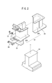
図2及び図3に示すように、コイル18は、プレスにより打ち抜いた略T字状の鋼板を複数枚かしめて一体化した積層鋼板(コア)24と、積層鋼板24を絶縁するインシュレータ26、28と、インシュレータ26、28を介して積層鋼板24に巻回される線材12と、金属製のターミナル33、34とを有する。インシュレータ26、28は、例えば、PPS(ポリフェニレンサルファイド)で形成されており、線材12が巻回される巻枠(コイル巻回部)30(30A、30b)を有する。インシュレータ26、28は、それぞれ一部が重なり合って結合され、積層鋼板24と線材12とが電気的に絶縁される。
線材12の巻始め端部12aは、ターミナル33にカシメ及びカットされてこのターミナル33に固定されるとともに、線材12の巻終わり端部12bは、ターミナル34にカシメ及びカットされてこのターミナル34に固定される。
図1に戻り、コイル生成部20は、インシュレータ26、28を装着した積層鋼板24を回転自在に保持するクランプ治具40と、該クランプ治具40を回転させるスピンドル42と、線材12の供給向きを安定させるノズル44と、該ノズル44の上下方向(矢印A方向)の位置を調整して線材12を多層に整列させる直交軸型ロボット46とを有する。スピンドル42はモータ(スピンドルモータ)48(コイル回転機構)に軸支されスピンドルモータ48の回転作用下に一定速度で回転する。直交軸型ロボット46はリニアモータによる高速動作が可能である。
コイル生成部20とテンション機構22との間には、線材12のテンションを計測するテンション計測部49が設けられており、リアルタイムで計測をしたテンションを制御装置23に供給する。
供給ボビン14は、開閉式のボックス50内に軸支されて設けられており、複数の室内プーリ52を介して線材12の供給を行う。供給ボビン14は、ボビンモータ15(ボビン回転機構)の軸に軸支され制御装置23の制御下に回転速度を調整可能である。
テンション機構22は、ボックス50の上部に配置されたベース板60上に各軸が平行に設けられたプーリ56、62、64、68とテンションローラ70と、ベース板60の裏面に設けられたリニアテンショナとしてのリニアモータ76とから構成される。
テンションローラ70は、ベース板60に水平方向に設けられたスリット80を介してリニアモータ76に接続されており、リニアモータ76に回転自在に軸支されている。リニアモータ76は、テンションローラ70を水平方向(矢印B方向)に移動する。
ボックス50から繰り出された線材12は、プーリ56、62、64、68を経てテンションローラ70に巻き掛けられた後、テンション計測部49、ノズル44を通じてコイル生成部20まで引き出される。
制御装置23によりリニアモータ76を介してテンションローラ70を水平方向(矢印B方向)に移動させることで、線材12に対するテンションが調整される。
次に、このように構成される巻線装置10において、線材12を掛け回す手順について説明する。
先ず、制御装置23はリニアモータ76を駆動してテンションローラ70をスリット80に沿って水平方向(矢印B方向)左端(テンション計測部49側)の待機位置(原点)まで移動しておく。
次に、線材12を供給ボビン14から引き出し、室内プーリ52、52、52を介してベース板60のプーリ56に対して図示の経路で線材12を巻き掛ける。
さらに、プーリ56からプーリ62、64、68を介してテンションローラ70に対して図示の経路で線材12を巻き掛ける。
線材12は、テンションローラ70からさらにテンション計測部49を介してコイル生成部20まで引き出して巻枠30に止める。このような線材12の引き回しは所定の自動機により自動的に行ってもよく、人手によって行ってもよい。
次に、リニアモータ76によりテンションローラ70をスリット80の略中間位置にまで移動させる。これによりテンションローラ70は、待機位置から作用側に移り線材12にテンションが掛けられる。テンションローラ70は、スリット80の略中間位置に配置されることから、線材12に対するテンションの調整代を大きくすることができる。
以上のようにして、線材12が供給ボビン14から積層鋼板24(巻枠30)まで所定のテンションを持った状態で掛け回される。
次に、巻線工程を開始する。つまり、ボビンモータ15が回転開始されると、供給ボビン14から線材12が繰り出される一方、コイル生成部20のスピンドル42をスピンドルモータ48により回転させ線材12を巻き取って巻枠30(図2も参照)に巻回し、コイル18を生成する。このとき、テンション機構22では、線材12のテンションが適値となるように、テンション計測部49で計測されたテンションが適値のテンションとなるように、制御装置23の作用下にリアルタイムにリニアモータ76をフィードバック制御(PID制御)する。
この巻線工程を実行する制御装置23の構成と作用を以下に説明する。
最初に、制御装置23の構成と基本的な作用について説明する。制御装置23は、コンピュータ及びDSP等により構成され、CPUが各種入力に基づきROM等のメモリに記憶されているプログラムを実行することで各種の機能を実現する機能実現部(機能実現手段)として動作する。
図4に示すように、この実施形態において、制御装置23は、演算部100と、この演算部100よりコイル(巻枠又はコア)回転指令を受けるコイル回転数制御部102と、演算部100よりボビン回転指令(回転数とタイミング)を受けるボビン回転数制御部104と、演算部100よりタイミング指令(原点、層切替)を受けるテンション制御部106として機能する。
コイル回転数制御部102は、演算部100からコイル回転指令を受けてコイル回転数目標値Nctar(この実施形態では、例えば1000[rpm]一定値)でスピンドルモータ48を回転させることで巻枠30を回転させコイル18を生成する。
スピンドルモータ48にはエンコーダ108が設けられ、エンコーダ108により検出されたコイル実回転数Nceが、コイル回転数制御部102に供給されることでコイル回転数制御部102はスピンドルモータ48のコイル実回転数Nceがコイル回転数目標値Nctarとなるようにフィードバック制御する。コイル実回転数Nceは、演算部100にも供給される。なお、実際上、コイル実回転数Nceは、エンコーダ108からのパルスをコイル回転数制御部102及び演算部100でカウントすることで算出される。
その一方、ボビン回転数制御部104は、演算部100からボビン回転指令(回転数とタイミング)を受けて、より具体的には、コイル18の層毎に異なるボビン回転数目標値Nbtarとその切替タイミングを演算部100より受けてボビンモータ15を回転させる。
ボビンモータ15には、エンコーダ110が設けられ、エンコーダ110により検出されたボビン実回転数Nbeが、ボビン回転数制御部104に供給されることでボビン回転数制御部104はボビンモータ15のボビン実回転数Nbeがボビン回転数目標値Nbtarとなるようにフィードバック制御する。ボビン実回転数Nbeは、演算部100にも供給される。この場合にも、実際上、ボビン実回転数Nbeは、エンコーダ110からのパルスをボビン回転数制御部104及び演算部100でカウントすることで算出される。
供給ボビン14のボビン外径φD(図1参照)は、供給ボビン14から線材12が繰り出されることで減少するが、このボビン外径φDは、供給ボビン14の近傍に配設された近接センサ112により検出(測定)され演算部100に供給される。
ボビン外径φDは、コイル18の外径φdに比較して、きわめて大きいので、1個のコイル18(線材多層整列コイル)の生成中には、ボビンφDは、φD=一定とみなせる。
図4において、テンション制御部106には、テンション計測部49により計測されるテンション(張力)検出値Tf[N]が供給され、テンション制御部106は、演算部100からの層切替(コイル18の巻層の切替)タイミング指令に応じて、このテンション検出値Tfが層切替に係わらず適値(所定値)であるテンション目標値Tftarとなるようにリニアモータ76を駆動してテンションローラ70を移動し、テンションをフィードバック制御する。
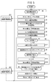
次に、基本的には、以上のように構成されかつ作用する制御装置23の詳しい作用について図5のフローチャートを参照しながら説明する。
ステップS1において制御装置23の演算部100は、図示しない上位装置あるいは入力装置から巻線開始指令を受けると、ステップS2において、演算部100は、コイル回転数制御部102、ボビン回転数制御部104、及びテンション制御部106に初期設定を行うよう指令を送る。
このステップS2における初期設定では、コイル回転数制御部102は、コイル回転数目標値Nctarを自身の設定メモリに設定するとともに、テンション制御部106は、テンション目標値Tftarを自身の設定メモリに設定する。ボビン回転数目標値Nbtarの初期値(コイル18の1層目のボビン回転数目標値Nbtar)は、演算部100からボビン回転数制御部104の設定メモリに設定される。
この場合、コイル18の1層目のボビン回転数目標値Nbtarは、演算部100において、コイル回転数目標値Nctarと、予め記憶している巻枠30の外周長(長方形)の円の直径換算値である外径φd(1層目)と近接センサ112により測定したボビン外径φDの比から算出される(Nbtar=Nctar×φd/φD)。
ここで、ステップS3以降の処理を説明する前に、この実施形態に係る処理の意義を理解し易くするため、比較例の処理による不都合について説明しながら、図5のフローチャートによる処理の要点(特徴)を説明する。
図6Aは、比較例に係る時間の経過とボビン回転数Nb[rpm]との関係を示している。時間軸は1目盛間隔が1[s]である。
時点Tc1でボビン回転数目標値Nbtarの指令値をボビンモータ15に出力すると、供給ボビン14のイナーシャのために、ボビン実回転数NbeはS字曲線で遅延しながら回転数が上昇し、時点tc1でボビン回転数目標値Nbtarとボビン実回転数Nbeが一致する。
一方、コイル回転数目標値Nctarの指令値は時点Tc1で同時にスピンドルモータ48に出力されるが、スピンドル42のイナーシャが小さいので、略その時点Tc1からコイル実回転数Nceが、コイル回転数目標値Nctarと一致する(図6A中、上側参照)。
時点Tc1から時点Tc2までの間は、コイル18の1層目(最下層)の巻線が巻枠30に巻回されている時間である。
同様に、時点Tc2でコイル18の2層目ボビン回転数目標値Nbtar(図6Aに示すように、2層目ボビン回転数目標値Nbtarは、コイル18の外径φdが大きくなって一定時間当たりの巻取量が増加する分に対応して増加させている。)を出力すると、この場合にも供給ボビン14のイナーシャのために、ボビン実回転数NbeはS字曲線で遅延して回転数が上昇し、時点tc2でボビン回転数目標値Nbtarとボビン実回転数Nbeが一致する。
以下、1つのコイル18の最外層の6層目の巻き終了時点Tc7まで同様に推移する。
この場合、図7Aに示す比較例に係る供給ボビン14からの線材12の繰出量Lrと、巻枠30への巻取量Lwの関係に示すように、コイル18の巻取量Lw[m]に対し供給ボビン14からの繰りだし量Lr[m]は、遅延時間{コイル軸(の回転)に対するボビン軸(の回転)の遅延時間又は、単にボビン軸遅延時間ともいう。}Δtdの経過時点で同一値となる。
しかしながら、この図6A、図7Aに示す比較例に係る巻線方案でスピンドルモータ48とボビンモータ15を回転制御するためには、コイル18と供給ボビン14ではイナーシャの差及び外径φd、φDの差が大きいためテンション機構に過大な負荷がかかる。すなわち、テンション機構が、図示しないブレーキローラ等が必要なものとなって大掛かりなものとなりかつ複雑になる。
以上の処理が比較例の処理とその不都合の説明である。
この出願の発明者は、比較例の処理において、図7Aに示す供給ボビン14の繰出量Lrとコイル18の巻取量Lwの差分ΔLに係わる遅延時間Δtdは、図6Aに示す階段状の指令であるボビン回転数目標値NbtarとS字曲線となるボビン実回転数Nbeとで形成されるハッチング部分の積分値に相当すると考えた。
そこで、この実施形態では、図6Bに示すように、スピンドルモータ48の回転開始時点Tc1に先立つ時点Tc1´で1層目ボビン回転数目標値Nbtarの指令をボビン回転数制御部104からボビンモータ13に送るようにした。
スピンドルモータ48の回転開始時点Tc1(図6Aと同一時点であることに留意する。)に先立つボビンモータ15の1層目の回転開始時点Tc1´は、図6Aに示した1層目ボビン回転数目標値Nbtarと1層目実回転数Nbeが一致する時点tc1を考慮し、次の(1)式により決定することができる。
Tc1´=Tc1-Δtd≒Tc1-(tc1-Tc1)/2 …(1)
同様に、2層目のボビン回転数目標値Nbtarの指令時点Tc2´は、次の(2)式により決定できることが分かる。
Tc2´=Tc2-Δtd-2層目の遅延時間分
≒Tc2-Δtd-(tc2-Tc2)/2 …(2)
≒Tc2-Δtd-(tc2-Tc2)/2 …(2)
一般的に、2層目以降n層目のボビン回転数目標値Nbtarの指令時点Tcn´は、次の(3)式により決定できることが分かる。
Tcn´=Tcn-Δtd-n層目までの遅延時間分の累積値
≒Tcn-Δtd-Σ(tcn-Tcn)/2 …(3)
≒Tcn-Δtd-Σ(tcn-Tcn)/2 …(3)
なお(3)式において、nは、n≧2である。
このように、次回の巻線工程においては、コイル18の各層において、ボビン遅延時間Δtdの概ね1/2の時間{1層目はΔtd/2、2層目以降は、このΔtd/2に内層(前に巻回した層)と外層(今から巻回しようとする層)の回転数差に基づく供給ボビン14のイナーシャを原因とする遅延時間を更に考慮した上記(3)式による計算される時間。}だけボビンモータ15の回転開始時点を早めるように制御することにより、図7Bに示すように、スピンドルモータ48のコイル18の1層目の巻回開始時点Tc1からコイル18の6層目の巻回開始時点Tc6´までの各巻回開始時点Tc1、Tc2´~Tc6´におけるコイル18の巻取量Lwと供給ボビン14の繰出量Lrを時々刻々略一致させることができる。
このため、この実施形態では、テンション機構を図1に示したリニアモータ76とテンションローラ70を利用した、ブレーキローラ等を使用しない簡素な構成のテンション機構22を採用することができる。
なお、スピンドルモータ48の回転開始時点Tc1に先立つ時点Tc1´は、遅延時間Δtdに依存し、この遅延時間Δtdは、ボビン回転数Nbと供給ボビン14のイナーシャに依存することから、予めボビン回転数Nbとボビン外径φDとを変数とし遅延時間Δtdを関数{Δtd=f(Nb,φD)]とした時点Tc1´の表(テーブル、マップ)を作成し、演算部100のメモリ(ROM)に記憶させておくようにする。
図7Bに示したように、上述した新方案の巻取・繰出制御を行うことにより巻取量Lwと繰出量Lrとの差分ΔL(図7A参照)を解消することができるが、この新方案の巻取・繰出制御を行っても、図7Bの制御終了時点Tc7´以降の繰出量Lwと巻取量Lrとの間に差分である総繰出量誤差ΔLt[m]が発生する。次に、この総繰出量誤差ΔLtをゼロにする方案について説明する。
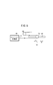
総繰出量誤差ΔLt[m]は、図8に示すように、テンションローラ70の矢印B方向の基準位置X0からの位置ずれ量xの2倍になることが分かる。
ΔLt=2×x …(4)
この位置ずれ量xは、テンション機構22で線材12にテンションを適値にかけるために発生するものであり、一般にゼロ値とすることはコスト的にきわめて難しい。
そこで、この位置ずれ量xを許容しながらも、総繰出量誤差ΔLt[m]をゼロ値とするために、可変することが(変更することが)可能なボビン回転数目標値Nbtarを次回の巻回時に補正する。なお、スピンドルモータ48のコイル回転数Ncは一定であるので補正しない。
この場合、次回の巻線時の繰出量補正係数K´を今回の繰出量補正係数Kから次の(5)式により算出する。
K´=K×(ΔLt-L)/L …(5)
ここで、K´:次回の巻線時の繰出量補正係数
K:今回の巻線時の繰出量補正係数
ΔLt:今回の巻線時の総繰出量誤差
L:基準総繰出量
K:今回の巻線時の繰出量補正係数
ΔLt:今回の巻線時の総繰出量誤差
L:基準総繰出量
この繰出量補正係数K´を利用して、次回のボビン回転数目標値Nbtar´を今回のボビン回転数目標値Nbtarに対して、次の(6)式により補正することができる。
Nbtar´=Nbtar×K´
=Nbtar×K×(ΔLt-L)/L …(6)
=Nbtar×K×(ΔLt-L)/L …(6)
ここで、基準総繰出長Lは、次の(7)式により算出することができる。
L=ΣπD×Nbe×Δt …(7)
ただし、Σの範囲は、巻線開始時点t=0から制御処理時間Δt毎に繰出長を計算する巻線時間tendまでの範囲である。この巻線時間tendは、1つのコイル18の巻線時間(図6Bに示す時点Tc1´から時点Tc7´までの時間)であり、Σの計算回数は、tend/Δtとなる。
(7)式において、πは円周率、Dはボビン外径、Nbeはボビン実回転数である。Δtは制御処理時間であり、ラダープログラムを使用するシーケンサに模して説明すると、いわゆるラダー実行間隔に対応する。例えば、Δt=0.004[s]に選択される。
このように次回のボビン回転数目標値Nbtar´を補正することで、図9に示すように、コイル18の巻取量Lw(実線)と供給ボビン14の繰出量Lr(点線)との総繰出量誤差ΔLtを略ゼロ値にすることができる。
以上の説明が、比較例の処理の不具合に対比させて説明したこの実施形態に係る図4に示す、これから説明しようとするフローチャートによる処理の要点の説明である。
そこで、ステップS3において、ステップS2で設定されたボビン回転数目標値Nbtarの初期値によりボビンモータ15の回転を開始させることで供給ボビン14の回転を開始させる(ボビン軸回転開始ともいう。)。
次に、ステップS3の処理(ボビン軸回転開始時点)と同時にステップS4において、演算部100は、コイル18のn(nは2~6)層目を巻くための2層目以降のボビン回転数目標値Nbtarの指令の出力時点Tcn´{上記(3)式}を決定するための計時を、タイマ(2層目以降のボビン回転数目標値Nbtar指令の出力時点決定用計時部)101により開始する。
また、ステップS3の処理(ボビン軸回転開始時点)と同時に、ステップS5において、ボビン回転数目標値Nbtarとボビン軸イナーシャの吸収のための、いわゆるS字曲線加減速制御によりボビン回転数指令値Nbcomを算出し回転制御を開始する。なお、このボビン回転数指令値Nbcomにより制御することで、図6Bに示すように、ボビン回転数指令値Nbcomがボビン実回転数Nbeに略等しくなる。
また、ステップS3の処理と同時に、ステップ6において、スピンドルモータ48の回転開始を待機させる(コイル軸の回転開始を待機又はコイル軸回転待機ともいう。)。このコイル軸回転開始待機時間は、ボビン遅延時間Δtd=Tc1´-Tc1に等しい(図6A、図7A参照)。
次いで、ステップS7において、タイマ101によるボビン遅延時間Δtdの経過時点Tc1(図6B参照)でスピンドルモータ48の回転を開始させ(コイル軸回転開始ともいう。)、巻枠30にコイル18の1層目の線材12の巻回を開始させる。
次に、ステップS8において、2層目以降のボビン回転数目標値Nbtarの指令の出力時点Tcn´までのタイマ101による計時が終了したかどうかが判定され、計時が終了していない場合には、ステップS8において、演算部100は、エンコーダ108の出力のコイル実回転数Nce(実際にはパルス)から巻回数カウンタ103(計数部)をカウントアップする。
次いで、ステップS10において、巻回数カウンタ103の計数値(カウント値)から巻層数が増加したかどうかを判定する。この巻層数の増加は、予めコイル回転数制御部102及び演算部100に記憶されている、コイル軸の巻回回数がy1回まで1層目、y2回までが2層目、…、yn回までがn層目とのテーブル(マップ)を参照して演算部100が判断する。
次いで、ステップS11において、巻回数カウンタ103の計数値が1個のコイル18分、すなわち1ワーク分終了値になったかどうかが判断される。
1ワーク終了値になっていないとき、ステップS8にもどり、タイマ101による計時が、2層目以降のボビン回転数目標値Nbtarの指令の出力時点Tcn´{上記(3)式}に達したとき、ステップS12において、該当する2層目以降のボビン回転数目標値Nbtarの指令を出力し、ボビン回転数制御部104を通じてボビンモータ15を回転させる。
ステップS9において、さらに、巻回数カウンタ103がカウントアップされ、ステップS10において、巻層数が増加したと判定されたとき、ステップS13において、層数nが1層分加算され(n←n+1)、ステップS14において、ステップS5と同様に、2層目以降のボビン回転数目標値Nbtarとボビン軸イナーシャの吸収のための、いわゆるS字曲線加減速制御によりボビン回転数指令値Nbcomを算出し回転制御、この場合2層目以降の回転制御を開始する。
このようにして制御を繰り返し、ステップS11において、巻回数カウンタ103の計数値が1ワーク分終了値になったときに、ステップS15において、近接センサ112によりボビン径φDが計測され、テーブルを参照して次回の新たなコイル18生成のための1層目のボビンモータ15の回転開始時点Tcn´が算出されてメモリに保存され、次回のステップS1の巻線開始指令の受領時にステップS3で読み出される。
また、ステップS16において、今回の繰出量補正係数Kから次回の巻線時の繰出量補正係数K´を上記(5)式により算出し、算出した繰出量補正係数K´を利用して、次回のボビン回転数目標値Nbtar´を今回のボビン回転数目標値Nbtarに対して、上記(6)式により補正して算出しておき、次のステップS2において、ボビン回転数制御部104の設定メモリに設定する。
なお、ステップS3においてボビン軸(ボビンモータ15と供給ボビン14)が回転開始したとき、ステップS21において演算部100からの開始指令によりテンション機構22が作動を開始し、テンション計測部49で計測したテンション値Tfが適値(テンション目標値Tftar)となるように、リニアモータ76を通じてテンションローラ70をPIDフィードバック制御する。このテンション機構22の作動は、1つのコイル18の巻回が終了したとき(ステップS11成立時)に演算部100からテンション制御部106に対して停止指令が送出され、テンション制御部106は、ステップS22においてテンション機構22を司るリニアモータ76の作動を停止させる。
以上説明したように上述した実施形態に係る巻線装置10は、線材12を供給する供給ボビン14を回転させるボビン回転機構としてのボビンモータ15と、供給ボビン14から供給される線材12をノズル44を介して巻枠30に整列させながら巻回してコイル18を生成するコイル回転機構としてのスピンドルモータ48と、ボビンモータ15及びスピンドルモータ48の回転数Nb、Ncを制御する制御装置23と、を備える。
制御装置23は、一定速度のコイル回転数目標値Nctarを設定するコイル回転数設定部としてのコイル回転数制御部102と、コイル回転数目標値Nctar、コイル径φd、及び供給ボビン径φDに基づいてボビン回転数目標値Nbtarを算出するボビン回転数目標値算出部としての演算部100と、コイル18のコイル実回転数Nce及びコイル径φDからコイル18として巻枠30に巻き取られる線材12の巻取量Lwを算出する巻取量算出部としての演算部100と、供給ボビン14を回転するボビンモータ15からボビン実回転数Nbe及び供給ボビン径φDから供給ボビン14から繰り出される線材12の繰出量Lrを算出する繰出量算出部としての演算部100と、算出された巻取量Lw及び算出された繰出量Lrから算出される供給ボビン14の繰出遅れ時間Δtdに基づいて、ボビン回転数目標値Nbtarでボビンモータ15を回転開始させるタイミング(図6Bに示した、回転開始時点Tc1´、Tc2´・・・Tc6´)をボビン回転数制御部104を通じてボビンモータ15に設定するタイミング設定手段としての演算部100と、を備える。
すなわち、巻枠30側で巻き取られる線材12の巻取量Lwと、供給ボビン14から繰り出される線材12の繰出量Lrとの差に基づき、コイル18の回転に対する供給ボビン14の回転(回転数と、回転数変更のタイミング)を、コイル18の線材12の巻取量Lwと供給ボビン14の線材12の繰出量Lrとが時々刻々一致するように制御しているので、コイル18と供給ボビン14とのイナーシャ・径に大きな差があっても、テンション変動を高精度に抑制することができる。
例えば、コイル回転数は、1000[rpm]程度一定とされ、ボビン回転数は、その1/10~1/20程度の範囲とされる(コイル回転数>>ボビン回転数)。この発明によれば、テンション変動を高精度に抑制しながら短時間で線材12が多層に整列されたコイル18を生産(量産)することができる。
この場合、制御装置23は、巻枠30に巻き付けられるコイル18の層数に応じて、各層のボビン回転数目標値Nbtarを算出し、前記各層のボビン回転開始又は回転数切り替えのタイミングを設定する。このようにすれば、コイル18のような整列巻コイルにおいて、巻層(コイル18の層数)に応じてコイル18の外径φdが大きくなってコイル18の1回転当たりの巻取量が増加することに対応させて、実ボビン回転数Nbeが大きくなるように制御したので、さらに高精度にテンション変動を抑制することができる。
また、供給ボビン14と巻枠30との間の線材繰出経路に線材12を巻枠30に巻き付ける際に発生するテンション変動を緩衝する線材12が巻き掛けられるテンション機構22を設けているが、この実施形態では、コイル18による線材12の巻取量(コイル巻取量)Lwと供給ボビン14からの線材12の繰出量(ボビン繰出量)Lrとの差が少なくなるため、テンション機構22のプーリであるテンションローラ70の変位量xが小さくなり、テンション機構22を小型・簡素化することができる。その結果、テンション変動抑制のためのブレーキローラ機構を使用する等の大掛かりで複雑な機構を採用する必要がなく、例えば、構成の簡素なリニアテンショナ、この実施形態ではリニアモータ76によるテンション機構22のみを用いることができる。
この場合、制御装置23の演算部100は、次回の巻線時のコイル巻取量Lwとボビン繰出量Lrとの偏差である総繰出量誤差ΔLtがなくなるように、リニアモータ76の位置ずれ量xと今回巻線時の線材の総繰出量である基準総繰出長Lに基づいて、次回のボビン回転数目標値Nbtar´を算出するボビン回転数目標値補正部をさらに備えることで、1コイルの累積巻線ずれである総繰出量誤差ΔLtをなくすることができる。
この発明に係る巻線装置は、上述の実施の形態に限らず、この発明の要旨を逸脱することなく、種々の構成を採り得ることはもちろんである。
Claims (6)
- 線材(12)を供給する供給ボビン(14)を回転させるボビン回転機構(15)と、
前記供給ボビン(14)から供給される前記線材(12)をノズル(44)を介して巻枠(30)に整列させながら巻回してコイル(18)を生成するコイル回転機構(48)と、
前記ボビン回転機構(15)及び前記コイル回転機構(48)の回転数を制御する制御装置(23)と、を備え、
前記制御装置(23)は、
一定速度のコイル回転数を設定するコイル回転数設定部(102)と、
前記コイル回転数、前記コイル径、及び前記供給ボビン径に基づいてボビン回転数目標値を算出するボビン回転数目標値算出部(100)と、
前記コイルの実回転数及び前記コイル径から前記コイルとして前記巻枠に巻き取られる前記線材の巻取量を算出する巻取量算出部(100)と、
前記供給ボビンの実回転数及び前記供給ボビン径から前記供給ボビンから繰り出される前記線材の繰出量を算出する繰出量算出部(100)と、
算出された前記巻取量及び算出された前記繰出量から算出される前記供給ボビンの繰出遅れ時間に基づいて、前記ボビン回転数目標値で前記ボビン回転機構(15)を回転開始させるタイミングを設定するタイミング設定手段(100)と、
を備えることを特徴とする巻線装置(10)。 - 請求項1記載の巻線装置(10)において、
前記制御装置(23)は、
前記巻枠(30)に巻き付けられる前記コイル(18)の層数に応じて、各層の前記ボビン回転数目標値を算出し、前記各層の前記ボビン回転開始又は回転数切り替えのタイミングを設定することを特徴とする巻線装置(10)。 - 請求項1に記載の巻線装置(10)において、
前記供給ボビン(14)と前記巻枠(30)との間の線材繰出経路に前記線材(12)を前記巻枠(30)に巻き付ける際に発生するテンション変動を緩衝する前記線材(12)が巻き掛けられるテンション機構(22)を設ける
ことを特徴とする巻線装置(10)。 - 請求項3記載の巻線装置(10)において、
前記テンション機構(22)をリニアテンショナとし、
前記制御装置(23)は、次回の巻線時のコイル巻取量とボビン繰出量との偏差である総繰出量誤差がなくなるように、前記リニアテンショナの位置ずれ量と今回巻線時の線材の総繰出量に基づいて、次回のボビン回転数目標値を算出するボビン回転数目標値補正部(100)をさらに備える
ことを特徴とする巻線装置(10)。 - 請求項2に記載の巻線装置(10)において、
前記供給ボビン(14)と前記巻枠(30)との間の線材繰出経路に前記線材(12)を前記巻枠(30)に巻き付ける際に発生するテンション変動を緩衝する前記線材(12)が巻き掛けられるテンション機構(22)を設ける
ことを特徴とする巻線装置(10)。 - 請求項5記載の巻線装置(10)において、
前記テンション機構(22)をリニアテンショナとし、
前記制御装置(23)は、次回の巻線時のコイル巻取量とボビン繰出量との偏差である総繰出量誤差がなくなるように、前記リニアテンショナの位置ずれ量と今回巻線時の線材の総繰出量に基づいて、次回のボビン回転数目標値を算出するボビン回転数目標値補正部(100)をさらに備える
ことを特徴とする巻線装置(10)。
Priority Applications (3)
| Application Number | Priority Date | Filing Date | Title |
|---|---|---|---|
| US13/000,335 US8844858B2 (en) | 2008-06-27 | 2009-06-01 | Wire winding device |
| EP09769982.1A EP2306473B1 (en) | 2008-06-27 | 2009-06-01 | Wire winding device |
| CN2009801238584A CN102067255B (zh) | 2008-06-27 | 2009-06-01 | 卷线装置 |
Applications Claiming Priority (2)
| Application Number | Priority Date | Filing Date | Title |
|---|---|---|---|
| JP2008168503A JP4827892B2 (ja) | 2008-06-27 | 2008-06-27 | 巻線装置 |
| JP2008-168503 | 2008-06-27 |
Publications (1)
| Publication Number | Publication Date |
|---|---|
| WO2009157272A1 true WO2009157272A1 (ja) | 2009-12-30 |
Family
ID=41444342
Family Applications (1)
| Application Number | Title | Priority Date | Filing Date |
|---|---|---|---|
| PCT/JP2009/059948 Ceased WO2009157272A1 (ja) | 2008-06-27 | 2009-06-01 | 巻線装置 |
Country Status (5)
| Country | Link |
|---|---|
| US (1) | US8844858B2 (ja) |
| EP (1) | EP2306473B1 (ja) |
| JP (1) | JP4827892B2 (ja) |
| CN (1) | CN102067255B (ja) |
| WO (1) | WO2009157272A1 (ja) |
Cited By (3)
| Publication number | Priority date | Publication date | Assignee | Title |
|---|---|---|---|---|
| ITPI20100075A1 (it) * | 2010-06-21 | 2011-12-22 | Atop Spa | Apparecchiature e metodi per avvolgere supporti per bobine e poli singoli di nuclei per macchine dinamo elettriche applicando tensioni predeterminate sul filo |
| WO2011160806A1 (en) * | 2010-06-21 | 2011-12-29 | Atop S.P.A. | Apparatus and method for winding supports for coils and single poles of cores for dynamoelectric machines |
| CN107481854A (zh) * | 2017-09-22 | 2017-12-15 | 广东电网有限责任公司电力科学研究院 | 一种高温超导双饼线圈绕线机 |
Families Citing this family (31)
| Publication number | Priority date | Publication date | Assignee | Title |
|---|---|---|---|---|
| ITPI20080023A1 (it) | 2008-03-19 | 2009-09-20 | Atop Spa | Apparecchiature e metodi per avvolgere supporti per bobine e poli singoli di nuclei per macchine dinamo elettriche |
| CN102285557A (zh) * | 2011-07-06 | 2011-12-21 | 陈建文 | 一种线绳的张力放线装置 |
| CN102910486B (zh) * | 2011-08-03 | 2015-01-07 | 台达电子企业管理(上海)有限公司 | 绕线器及缠绕电线于绕线器的方法 |
| CN102324815A (zh) * | 2011-09-20 | 2012-01-18 | 无锡锡山安达防爆电气设备有限公司 | 数控变频绕线机 |
| ITMI20112414A1 (it) * | 2011-12-28 | 2013-06-29 | Btsr Int Spa | Sistema e metodo perfezionati per alimentare a tensione costante fili metallici |
| JP5930536B2 (ja) * | 2012-07-03 | 2016-06-08 | 日特エンジニアリング株式会社 | 巻線装置及び巻線方法 |
| ITMI20122185A1 (it) * | 2012-12-20 | 2014-06-21 | Btsr Int Spa | Metodo e dispositivo per alimentare a tensione ed a quantita' costante un filo metallico ad una macchina operatrice |
| DE102014108208A1 (de) * | 2014-06-11 | 2015-12-17 | Friedrich-Alexander-Universität Erlangen-Nürnberg | Drahtführelement, Drahtwickelmaschine mit einem solchen, Verfahren zum Einbringen von Draht und Verfahren zum Zuführen von Draht |
| KR101627344B1 (ko) | 2014-09-30 | 2016-06-07 | 부경대학교 산학협력단 | 장력제어형 bldc모터 코일 와인딩장치 |
| CN104485788B (zh) * | 2014-12-09 | 2017-05-17 | 遵义天义利威机电有限责任公司 | 一种定子线圈绕制用自动上丝装置 |
| JP6110451B1 (ja) * | 2015-09-30 | 2017-04-05 | ファナック株式会社 | 機械学習装置およびコイル製造装置 |
| CN105742053A (zh) * | 2016-04-26 | 2016-07-06 | 江苏雷特电机股份有限公司 | 一种电磁线绕线装置 |
| JP6900008B2 (ja) * | 2016-08-01 | 2021-07-07 | 株式会社大垣化工 | 糸巻取機 |
| JP6824014B2 (ja) * | 2016-12-01 | 2021-02-03 | 三菱電機株式会社 | 巻線装置 |
| ES2980482T3 (es) | 2016-12-12 | 2024-10-01 | Siemens Ag | Procedimiento para bobinar un producto a enrollar y máquina de bobinar |
| US11068840B2 (en) * | 2017-03-10 | 2021-07-20 | Scott A. Stensland | Device to calculate and display remaining length of a coiled product |
| CN106960724A (zh) * | 2017-03-31 | 2017-07-18 | 深圳市红昌机电设备有限公司 | 立式绕线机的脚控制方法及系统 |
| JP6347569B1 (ja) * | 2018-02-23 | 2018-06-27 | E−Tec株式会社 | 巻線装置 |
| CN108638391A (zh) * | 2018-06-04 | 2018-10-12 | 潍坊市精达塑料机械有限公司 | 一种钢丝塑胶管绕丝装置 |
| JP7083705B2 (ja) * | 2018-06-25 | 2022-06-13 | Nittoku株式会社 | 巻線装置及びそれを用いた巻線方法 |
| CN109205392A (zh) * | 2018-09-28 | 2019-01-15 | 安溪达亚齐机械设计有限公司 | 刺铆卷绕机 |
| EP3958448B1 (en) * | 2019-04-16 | 2024-05-08 | Rainbow Robotics | Stator coil winding device |
| JP7222829B2 (ja) * | 2019-06-24 | 2023-02-15 | 株式会社デンソー | 巻線装置 |
| WO2021106674A1 (ja) * | 2019-11-25 | 2021-06-03 | パナソニックIpマネジメント株式会社 | モータ巻線用ボビン |
| JP7336825B2 (ja) * | 2020-01-15 | 2023-09-01 | Nittoku株式会社 | 巻線装置及び巻線方法 |
| CN112850363B (zh) * | 2021-01-22 | 2022-02-22 | 北京航空航天大学 | 一种用于纤维束张力调控的变杆长刚柔耦合机构 |
| CN113589742B (zh) * | 2021-08-16 | 2024-03-29 | 贵州梓恒科技服务有限公司 | 一种绕线机数控系统 |
| CN115700896B (zh) * | 2022-11-14 | 2023-08-04 | 惠州市骅鹰电子科技有限公司 | 一种数千股线绞合的包膜线线圈的绕制设备及使用方法 |
| DE102023210338A1 (de) * | 2023-10-19 | 2025-04-24 | Vitesco Technologies GmbH | Verfahren für einen Wicklungsprozess, Wicklungsmaschine und Wicklungskörper |
| CN117476364B (zh) * | 2023-12-22 | 2024-03-12 | 日特机械工程(苏州)有限公司 | 一种绕线机控制方法及系统 |
| KR102841411B1 (ko) * | 2024-04-30 | 2025-08-01 | (주)카스윈 | 차량용 모터의 고정자 코일 와인딩 장치 |
Citations (3)
| Publication number | Priority date | Publication date | Assignee | Title |
|---|---|---|---|---|
| JPS5493451A (en) * | 1978-01-05 | 1979-07-24 | Tokyo Shibaura Electric Co | Material tension control device for winding unwinding device |
| JPH04292379A (ja) * | 1991-03-19 | 1992-10-16 | Mitsubishi Electric Corp | 張力制御装置 |
| JP2004104022A (ja) * | 2002-09-12 | 2004-04-02 | Nittoku Eng Co Ltd | 巻線機におけるテンション装置とテンション付与方法 |
Family Cites Families (8)
| Publication number | Priority date | Publication date | Assignee | Title |
|---|---|---|---|---|
| FR1226830A (fr) * | 1958-06-13 | 1960-08-16 | Poletti & Osta | Dispositif pour le réglage de la tension d'un ruban ou analogue enroulé sur un tambour ou se déroulant à partir de celui-ci |
| US4141515A (en) * | 1977-08-02 | 1979-02-27 | Corning Glass Works | Automated layer separator delivery system for optical waveguide winding |
| GB2043715B (en) * | 1979-03-08 | 1983-01-26 | Roose V I | Winding machine |
| JPS56126534A (en) * | 1980-03-07 | 1981-10-03 | Mitsubishi Electric Corp | Wire cut spark machining device |
| DE8704638U1 (de) * | 1987-03-28 | 1987-08-20 | Deißenberger, Hans, 7240 Horb | Umwickeleinrichtung |
| JPH11222357A (ja) | 1997-12-05 | 1999-08-17 | Nittoku Eng Co Ltd | 巻線装置および巻線方法 |
| JP3613994B2 (ja) * | 1998-02-12 | 2005-01-26 | トヨタ自動車株式会社 | 平角線コイル製造装置および平角線コイル製造方法 |
| DE10201118A1 (de) * | 2002-01-15 | 2003-07-24 | Neumag Gmbh & Co Kg | Verfahren zum Aufwickeln eines Fadens |
-
2008
- 2008-06-27 JP JP2008168503A patent/JP4827892B2/ja not_active Expired - Fee Related
-
2009
- 2009-06-01 WO PCT/JP2009/059948 patent/WO2009157272A1/ja not_active Ceased
- 2009-06-01 CN CN2009801238584A patent/CN102067255B/zh not_active Expired - Fee Related
- 2009-06-01 EP EP09769982.1A patent/EP2306473B1/en not_active Not-in-force
- 2009-06-01 US US13/000,335 patent/US8844858B2/en not_active Expired - Fee Related
Patent Citations (3)
| Publication number | Priority date | Publication date | Assignee | Title |
|---|---|---|---|---|
| JPS5493451A (en) * | 1978-01-05 | 1979-07-24 | Tokyo Shibaura Electric Co | Material tension control device for winding unwinding device |
| JPH04292379A (ja) * | 1991-03-19 | 1992-10-16 | Mitsubishi Electric Corp | 張力制御装置 |
| JP2004104022A (ja) * | 2002-09-12 | 2004-04-02 | Nittoku Eng Co Ltd | 巻線機におけるテンション装置とテンション付与方法 |
Non-Patent Citations (1)
| Title |
|---|
| See also references of EP2306473A4 * |
Cited By (4)
| Publication number | Priority date | Publication date | Assignee | Title |
|---|---|---|---|---|
| ITPI20100075A1 (it) * | 2010-06-21 | 2011-12-22 | Atop Spa | Apparecchiature e metodi per avvolgere supporti per bobine e poli singoli di nuclei per macchine dinamo elettriche applicando tensioni predeterminate sul filo |
| WO2011160806A1 (en) * | 2010-06-21 | 2011-12-29 | Atop S.P.A. | Apparatus and method for winding supports for coils and single poles of cores for dynamoelectric machines |
| CN107481854A (zh) * | 2017-09-22 | 2017-12-15 | 广东电网有限责任公司电力科学研究院 | 一种高温超导双饼线圈绕线机 |
| CN107481854B (zh) * | 2017-09-22 | 2024-02-13 | 广东电网有限责任公司电力科学研究院 | 一种高温超导双饼线圈绕线机 |
Also Published As
| Publication number | Publication date |
|---|---|
| US20110114781A1 (en) | 2011-05-19 |
| JP2010010429A (ja) | 2010-01-14 |
| JP4827892B2 (ja) | 2011-11-30 |
| CN102067255A (zh) | 2011-05-18 |
| EP2306473A1 (en) | 2011-04-06 |
| CN102067255B (zh) | 2013-01-02 |
| EP2306473A4 (en) | 2011-12-28 |
| US8844858B2 (en) | 2014-09-30 |
| EP2306473B1 (en) | 2013-10-30 |
Similar Documents
| Publication | Publication Date | Title |
|---|---|---|
| JP4827892B2 (ja) | 巻線装置 | |
| TWI383942B (zh) | Winding device, tension device and winding method | |
| US9033271B2 (en) | Wire winding apparatus and wire winding method | |
| CN104030090B (zh) | 操作生产交叉卷绕筒子的纺织机的工位的方法及关联工位 | |
| JP2002043157A (ja) | 線材の巻線方法及び装置 | |
| EP0553898A2 (en) | Wire tensioner | |
| TW202128546A (zh) | 繞線裝置及繞線方法 | |
| JP2013252948A (ja) | 繊維機械 | |
| JP5385013B2 (ja) | テンション装置 | |
| JP2013028438A (ja) | テンション装置、自動巻線機、テンション制御方法、及び巻線の製造方法 | |
| JP4414779B2 (ja) | 線材の巻取方法 | |
| JP5079389B2 (ja) | 鉄心製造装置 | |
| JP7222829B2 (ja) | 巻線装置 | |
| JP7336825B2 (ja) | 巻線装置及び巻線方法 | |
| JP2006193334A (ja) | 綾巻きボビンを製造する繊維機械の作業部位を運転する方法及び装置 | |
| JPH0859081A (ja) | 細線用巻線機 | |
| JP7525380B2 (ja) | 巻線装置 | |
| JPH08227823A (ja) | コイル巻線装置 | |
| JP2685335B2 (ja) | 巻線装置 | |
| CN118414772A (zh) | 绕线装置、以及旋转电机的制造方法 | |
| JP4733469B2 (ja) | 巻線装置、及び巻線方法 | |
| CN104229550A (zh) | 筒子架旋转角位置的调节方法、纺织机及步进马达的应用 | |
| JPS58183568A (ja) | 自動整列巻線機 | |
| JPS63127983A (ja) | 整列巻線機における巻乱れの検知方法 | |
| KR20130134403A (ko) | 카메라를 이용한 권선기 |
Legal Events
| Date | Code | Title | Description |
|---|---|---|---|
| WWE | Wipo information: entry into national phase |
Ref document number: 200980123858.4 Country of ref document: CN |
|
| 121 | Ep: the epo has been informed by wipo that ep was designated in this application |
Ref document number: 09769982 Country of ref document: EP Kind code of ref document: A1 |
|
| WWE | Wipo information: entry into national phase |
Ref document number: 13000335 Country of ref document: US |
|
| WWE | Wipo information: entry into national phase |
Ref document number: 2009769982 Country of ref document: EP |
|
| NENP | Non-entry into the national phase |
Ref country code: DE |