WO2010001614A1 - 動画像符号化方法、動画像復号方法、動画像符号化装置、動画像復号装置、プログラム、及び集積回路 - Google Patents
動画像符号化方法、動画像復号方法、動画像符号化装置、動画像復号装置、プログラム、及び集積回路 Download PDFInfo
- Publication number
- WO2010001614A1 WO2010001614A1 PCT/JP2009/003086 JP2009003086W WO2010001614A1 WO 2010001614 A1 WO2010001614 A1 WO 2010001614A1 JP 2009003086 W JP2009003086 W JP 2009003086W WO 2010001614 A1 WO2010001614 A1 WO 2010001614A1
- Authority
- WO
- WIPO (PCT)
- Prior art keywords
- signal
- prediction
- filter information
- filter
- encoded
- Prior art date
- Legal status (The legal status is an assumption and is not a legal conclusion. Google has not performed a legal analysis and makes no representation as to the accuracy of the status listed.)
- Ceased
Links
Images


Classifications
-
- H—ELECTRICITY
- H04—ELECTRIC COMMUNICATION TECHNIQUE
- H04N—PICTORIAL COMMUNICATION, e.g. TELEVISION
- H04N19/00—Methods or arrangements for coding, decoding, compressing or decompressing digital video signals
- H04N19/85—Methods or arrangements for coding, decoding, compressing or decompressing digital video signals using pre-processing or post-processing specially adapted for video compression
- H04N19/86—Methods or arrangements for coding, decoding, compressing or decompressing digital video signals using pre-processing or post-processing specially adapted for video compression involving reduction of coding artifacts, e.g. of blockiness
-
- H—ELECTRICITY
- H04—ELECTRIC COMMUNICATION TECHNIQUE
- H04N—PICTORIAL COMMUNICATION, e.g. TELEVISION
- H04N19/00—Methods or arrangements for coding, decoding, compressing or decompressing digital video signals
- H04N19/10—Methods or arrangements for coding, decoding, compressing or decompressing digital video signals using adaptive coding
- H04N19/102—Methods or arrangements for coding, decoding, compressing or decompressing digital video signals using adaptive coding characterised by the element, parameter or selection affected or controlled by the adaptive coding
- H04N19/117—Filters, e.g. for pre-processing or post-processing
-
- H—ELECTRICITY
- H04—ELECTRIC COMMUNICATION TECHNIQUE
- H04N—PICTORIAL COMMUNICATION, e.g. TELEVISION
- H04N19/00—Methods or arrangements for coding, decoding, compressing or decompressing digital video signals
- H04N19/10—Methods or arrangements for coding, decoding, compressing or decompressing digital video signals using adaptive coding
- H04N19/134—Methods or arrangements for coding, decoding, compressing or decompressing digital video signals using adaptive coding characterised by the element, parameter or criterion affecting or controlling the adaptive coding
- H04N19/157—Assigned coding mode, i.e. the coding mode being predefined or preselected to be further used for selection of another element or parameter
- H04N19/159—Prediction type, e.g. intra-frame, inter-frame or bidirectional frame prediction
-
- H—ELECTRICITY
- H04—ELECTRIC COMMUNICATION TECHNIQUE
- H04N—PICTORIAL COMMUNICATION, e.g. TELEVISION
- H04N19/00—Methods or arrangements for coding, decoding, compressing or decompressing digital video signals
- H04N19/10—Methods or arrangements for coding, decoding, compressing or decompressing digital video signals using adaptive coding
- H04N19/169—Methods or arrangements for coding, decoding, compressing or decompressing digital video signals using adaptive coding characterised by the coding unit, i.e. the structural portion or semantic portion of the video signal being the object or the subject of the adaptive coding
- H04N19/17—Methods or arrangements for coding, decoding, compressing or decompressing digital video signals using adaptive coding characterised by the coding unit, i.e. the structural portion or semantic portion of the video signal being the object or the subject of the adaptive coding the unit being an image region, e.g. an object
- H04N19/176—Methods or arrangements for coding, decoding, compressing or decompressing digital video signals using adaptive coding characterised by the coding unit, i.e. the structural portion or semantic portion of the video signal being the object or the subject of the adaptive coding the unit being an image region, e.g. an object the region being a block, e.g. a macroblock
-
- H—ELECTRICITY
- H04—ELECTRIC COMMUNICATION TECHNIQUE
- H04N—PICTORIAL COMMUNICATION, e.g. TELEVISION
- H04N19/00—Methods or arrangements for coding, decoding, compressing or decompressing digital video signals
- H04N19/10—Methods or arrangements for coding, decoding, compressing or decompressing digital video signals using adaptive coding
- H04N19/189—Methods or arrangements for coding, decoding, compressing or decompressing digital video signals using adaptive coding characterised by the adaptation method, adaptation tool or adaptation type used for the adaptive coding
- H04N19/192—Methods or arrangements for coding, decoding, compressing or decompressing digital video signals using adaptive coding characterised by the adaptation method, adaptation tool or adaptation type used for the adaptive coding the adaptation method, adaptation tool or adaptation type being iterative or recursive
-
- H—ELECTRICITY
- H04—ELECTRIC COMMUNICATION TECHNIQUE
- H04N—PICTORIAL COMMUNICATION, e.g. TELEVISION
- H04N19/00—Methods or arrangements for coding, decoding, compressing or decompressing digital video signals
- H04N19/60—Methods or arrangements for coding, decoding, compressing or decompressing digital video signals using transform coding
- H04N19/61—Methods or arrangements for coding, decoding, compressing or decompressing digital video signals using transform coding in combination with predictive coding
-
- H—ELECTRICITY
- H04—ELECTRIC COMMUNICATION TECHNIQUE
- H04N—PICTORIAL COMMUNICATION, e.g. TELEVISION
- H04N19/00—Methods or arrangements for coding, decoding, compressing or decompressing digital video signals
- H04N19/80—Details of filtering operations specially adapted for video compression, e.g. for pixel interpolation
- H04N19/82—Details of filtering operations specially adapted for video compression, e.g. for pixel interpolation involving filtering within a prediction loop
-
- H—ELECTRICITY
- H04—ELECTRIC COMMUNICATION TECHNIQUE
- H04N—PICTORIAL COMMUNICATION, e.g. TELEVISION
- H04N19/00—Methods or arrangements for coding, decoding, compressing or decompressing digital video signals
- H04N19/85—Methods or arrangements for coding, decoding, compressing or decompressing digital video signals using pre-processing or post-processing specially adapted for video compression
Definitions
- the present invention relates to a moving image coding filter, and more particularly to a filter applied to a signal reconstructed from a prediction signal and a quantized prediction error signal in differential pulse code modulation.
- H.264 ITU-T As an example of the video coding standard, H.264 ITU-T standard called 26x and ISO / IEC standard called MPEG-x.
- MPEG-x The latest video coding standard is H.264. H.264 / MPEG-4AVC.
- the latest video coding standard is a differential pulse code modulation (DPCM) technique that transmits only the difference between a block of an input video sequence and a prediction result based on a coded block (partially decoded image).
- DPCM differential pulse code modulation
- One of prediction methods that can be used for such a moving image coding standard is motion compensation prediction.
- this prediction method at least one motion vector is specified for each block of moving image data in order to describe the displacement of the image caused by the motion of the object and / or camera. Based on the identified motion vector, the image content of a block can be predicted at least to some extent from the image content of the encoded block.
- the difference between the predicted image content and the actual input image content is called a prediction error and is encoded together with the motion vector instead of the actual input image content. In this way, it is possible to greatly reduce the amount of encoded information for most “natural” video sequences.
- FIG. 1 is an exemplary block diagram showing a conventional moving picture encoding apparatus according to the H.264 / AVC standard.
- the moving image encoding apparatus is obtained based on the encoding target block of the moving image (input signal) and the encoded block (“partially decoded image”) stored in the memory 140,
- a subtractor 110 is provided for obtaining a difference from the prediction signal of the encoding target block. Therefore, the memory 140 operates as a delay unit that enables comparison between a target signal value and a predicted signal generated from a previous signal value.
- the transform / quantization unit 120 transforms the obtained prediction error from the spatial domain to the frequency domain, and quantizes the acquired coefficient.
- the entropy encoding unit 190 entropy encodes the quantized coefficient.
- the partial decoded image is provided by a decoding unit incorporated in the video encoding device.
- the decoding unit executes the encoding steps in the reverse order.
- the inverse quantization / inverse transform unit 130 inverse quantizes the quantized coefficient and applies the inverse transform to the inverse quantized coefficient.
- the adder 135 the decoding error is added to the prediction signal to generate a partially decoded image.
- Quantization noise is superimposed on the reconstructed video signal by quantization. Due to the coding on a block basis, the superimposed noise often has a blocking characteristic and may be annoying.
- a deblocking filter 137 is applied to each reconstructed macroblock.
- the deblocking filter 137 is applied to a reconstructed signal obtained by adding a prediction signal and a quantized prediction error signal.
- the deblock signal is a decoded signal and is generally displayed.
- H The deblocking filter 137 in H.264 / AVC can be partially employed. When the degree of blocking noise is high, a strong low-pass filter is employed. On the other hand, when the level of blocking noise is low, a weak low-pass filter is employed. The strength of the low-pass filter is determined by the prediction signal and the quantized prediction error signal.
- the deblocking filter 137 has the following two merits.
- the block edges are smoothed, resulting in an improved subjective image quality of the decoded image.
- the filtered macroblock is used for motion compensated prediction of the subsequent image, the prediction error is reduced by filtering, and as a result, the coding efficiency is improved.
- the intra prediction macroblock is a special case in such a situation. These are filtered before being displayed, but in-screen prediction is performed using the reconstructed macroblock before filtering.
- a linear deblocking filter using four coefficients is given as an example of deblocking for a vertical block boundary.
- This filter is applied to the input samples p 2 , p 1 , p 0 , q 0 , q 1 and q 2 .
- p 0 and q 0 are two pixels adjacent to each other at the block boundary
- p 1 and q 1 are pixels adjacent to p 0 and q 0 .
- the prediction type employed in the video encoding apparatus is determined by whether the macroblock is encoded in the “inter-screen” mode or the “in-screen” mode.
- H. In the H.264 / AVC video coding standard, a prediction method based on a macroblock that has been encoded in the same image is used to predict a subsequent macroblock in the “in-screen” mode.
- motion compensation prediction is adopted between the same position blocks of a plurality of consecutive frames.
- I type image Only the intra-coded image (I type image) can be decoded without referring to the decoded image.
- An I-type image provides an encoded video sequence with error tolerance.
- these I-type images are provided as entry points to the bit stream that is the encoded data to enable random access, ie to access the I-type images in the encoded video sequence.
- the Switching between the intra-screen mode that is a process performed by the intra-frame frame prediction unit 150 and the inter-screen mode that is a process performed by the motion compensation prediction unit 160 is controlled by an intra-screen / inter-screen switch 180.
- a macro block is predicted from the same position block of the preceding frame by adopting motion compensation prediction. This prediction is performed by the motion prediction unit 170, and the target input signal and the partially decoded image are received. By motion prediction, a two-dimensional motion vector is obtained and represents the displacement between the same position block of the target block and the decoded frame. Based on the predicted motion, the motion compensated prediction unit 160 provides a prediction signal.
- the motion vector may be obtained with a decimal pixel resolution such as a 1/2 pixel resolution or a 1/4 pixel resolution.
- a decimal pixel resolution motion vector may point to a position in the decoded frame where there is no available pixel value, that is, a decimal pixel position. Therefore, in order to perform motion compensation, spatial interpolation of pixel values is necessary. This is achieved by the interpolation filter 162.
- the interpolation filter 162 To obtain the pixel value at the decimal pixel position, In accordance with the H.264 / AVC standard, a 6-tap Wiener interpolation filter with fixed filter coefficients and a bilinear filter are applied.
- the difference between the target input signal and the prediction signal is transformed and quantized by the transform / quantization unit 120 to obtain a quantized coefficient.
- an orthogonal transform such as a two-dimensional discrete cosine transform (DCT) or an integer version thereof is employed.
- the quantization step is controlled by a quantization table that specifies the accuracy and the number of bits used to encode each quantization coefficient with that accuracy.
- the low frequency component is more important to image quality than the high frequency component, so more bits are consumed to encode the low frequency component than the number of bits spent to encode the high frequency component.
- the two-dimensional array of quantized coefficients must be converted to a one-dimensional sequence for passing to the entropy encoder. This conversion is done by scanning the array in a predetermined order.
- the one-dimensional quantized coefficient sequence acquired in this way is compression-encoded by the entropy encoding unit 190 using a variable length code (VLC).
- VLC variable length code
- a so-called post filter may be applied on the moving image decoding apparatus side.
- the post filter information for the post filter can be transmitted by using the additional extension information (SEI) message.
- SEI additional extension information
- the post filter information may be the filter coefficients themselves, or may be cross-correlation information that can be used to obtain these filter coefficients.
- the post filter information is determined on the moving image coding apparatus side by the post filter design unit 138 and compared with the partial decoded signal and the original image input signal.
- the output of the post filter design unit 138 is also supplied to the entropy encoding unit 190 in order to be encoded and inserted into the encoded signal.
- FIG. 2 is a schematic block diagram illustrating the configuration of the corresponding video decoding device.
- the entropy decoding unit 191 performs entropy decoding on the coefficients and the motion data. This step also includes reverse scanning for converting the decoded coefficient sequence into two-dimensional array data necessary for reverse conversion.
- the decoded block of quantized coefficients is then provided to the inverse quantization / inverse transform unit 121, and the decoded motion data is transmitted to the motion compensation prediction unit 160.
- the motion compensation prediction unit 160 Depending on the actual value of the motion vector, it may be necessary to interpolate pixel values in order to perform motion compensation prediction. This interpolation is achieved by the interpolation filter 162.
- the inverse transformation result is a quantization prediction error in the spatial domain, and is added by the adder 135.
- the addition result is added to the prediction signal generated from the motion compensation prediction unit 160.
- the reconstructed image may be passed through the deblocking filter 137, and the obtained decoded signal is stored in the memory 140 to be applied to the intra-frame prediction unit 150 and the motion compensation prediction unit 160.
- the entropy decoding unit 191 also searches for a post filter specified by the encoder.
- the post filter 139 employs this information to set the post filter applied to the decoded signal for the purpose of further improving the image quality.
- the conventional post filter is an example of an adaptive filter, that is, a filter adapted to the characteristics of a moving image signal to be encoded.
- adaptive filters are based on Wiener filters, ie linear optimal time discrete filters.
- Wiener filter is generally applied to remove additional noise.
- a quantization error can be regarded as noise superimposed on an original moving picture input signal.
- the filter coefficient is obtained based on the autocorrelation of the damaged signal (decoded video signal) and the cross-correlation between the damaged signal and the desired signal (original moving image input signal). It can be done. More specifically, when R represents the M ⁇ M autocorrelation matrix of the corrupted signal and p represents the M ⁇ 1 cross-correlation vector between the corrupted signal and the desired signal, the filter length of the Wiener filter is M, The M ⁇ 1 vector of the optimal Wiener filter coefficient w is expressed using Equation 1 below.
- R ⁇ 1 is the reciprocal of the autocorrelation matrix R.
- an adaptive filter is applied in a prediction loop.
- an adaptive filter can be applied directly to the reconstructed signal, an adaptive filter can be applied to the output of the deblocking filter, To apply an adaptive filter.
- the purpose of conventional video filters is to increase subjective image quality by minimizing mean square prediction error and / or mean square reconstruction error, or deblocking the image, or both.
- this filtering format is effective only when the prediction signal and the quantized prediction error signal have the same statistical characteristics.
- the filter design is disadvantageous because the different statistical characteristics cannot be handled.
- the quantization noise is superimposed only on the prediction error during the quantization step, but not on the prediction signal itself at a certain time.
- the predicted signal may contain quantization noise at different times and thus may have different statistical characteristics.
- the edge of the block in motion compensation prediction may be different from the edge of the block in prediction error coding, and the blocking characteristic is different in the prediction signal compared to the quantized prediction error signal.
- An object of the present invention is to provide a moving picture coding method and a corresponding apparatus that improve coding efficiency.
- the moving image encoding method encodes a signal to be encoded constituting a moving image. Specifically, based on another encoding target signal encoded before the encoding target signal, a prediction signal generating step for generating a prediction signal predicting the encoding target signal, and the encoding target A quantization step for quantizing a prediction error obtained by subtracting the prediction signal from a signal to generate a quantization coefficient; and an inverse quantization step for dequantizing the quantization coefficient to generate a quantization prediction error signal;
- the first filter information is generated based on the statistical characteristic of only the prediction signal among the prediction signal and the quantized prediction error signal, and the first filter information is generated based on the statistical characteristic of only the quantized prediction error signal.
- Filter information generating step for generating the filter information of the second, the quantization coefficient generated in the quantization step, and the first generated in the filter information generating step.
- an entropy coding step of generating a coded signal and a second filter information to the entropy coding.
- noise superimposed on each of the prediction signal and the quantized prediction error signal can be individually removed. As a result, encoding efficiency can be improved.
- the filtered prediction signal obtained by filtering the prediction signal based on the first filter information and the quantized prediction error signal based on the second filter information are obtained.
- the first and second filter information are set such that the difference between the reconstructed signal obtained by adding the filtered quantized prediction error signal obtained by filtering and the encoding target signal is minimized. It may be generated. Thereby, the subjective image quality of the decoded image can be improved.
- the prediction signal generation step generates a filtered prediction signal by filtering the prediction signal based on the first filter information, and generates the quantized prediction error signal based on the second filter information. Filtering to generate a filtered quantized prediction error signal by filtering, adding the filtered predicted signal and the filtered quantized prediction error signal to generate a reconstructed signal, and based on the reconstructed signal.
- the first and second filter information may be applied to the loop filter.
- a deblocking process for reducing block distortion of the reconstructed signal is performed.
- an interpolation filtering process performed prior to motion compensation prediction is performed.
- third filter information is generated based on statistical characteristics of the reconstructed signal obtained by adding the prediction signal and the quantized prediction error signal.
- the encoded prediction signal may be entropy encoded with the quantized prediction error signal and the first, second, and third filter information to generate the encoded signal.
- third filter information used for a conventional post filter may also be generated.
- the moving picture decoding method generates a decoded signal by decoding a coded signal constituting a moving picture. Specifically, an entropy decoding step for entropy decoding the encoded signal to obtain quantized coefficients and first and second filter information, and a quantized prediction error signal by dequantizing the quantized coefficients.
- a dequantization step for generating a prediction signal a prediction signal generation step for generating a prediction signal for predicting the decoded signal based on another encoded signal decoded before the encoded signal, and the first filter Filtering the predicted signal based on information to generate a filtered predicted signal, and filtering the quantized prediction error signal based on the second filter information to generate a filtered quantized prediction error signal Filtering step for adding the filtered prediction signal and the filtered quantized prediction error signal to generate the decoded signal. Including the flop.
- noise superimposed on each of the prediction signal and the quantized prediction error signal can be individually removed, so that subjective image quality can be improved.
- the prediction signal generation step generates a filtered prediction signal by filtering the prediction signal based on the first filter information, and generates the quantized prediction error signal based on the second filter information. Filtering to generate a filtered quantized prediction error signal by filtering, adding the filtered predicted signal and the filtered quantized prediction error signal to generate a reconstructed signal, and based on the reconstructed signal.
- the first and second filter information can be applied not only to the post filter but also to the loop filter.
- the moving picture encoding apparatus encodes the encoding target signal constituting the moving picture. Specifically, based on another encoding target signal encoded before the encoding target signal, a prediction signal generation unit that generates a prediction signal that predicts the encoding target signal, and the encoding target A quantization unit that quantizes a prediction error obtained by subtracting the prediction signal from a signal to generate a quantization coefficient; and an inverse quantization unit that dequantizes the quantization coefficient to generate a quantization prediction error signal; The first filter information is generated based on the statistical characteristic of only the prediction signal among the prediction signal and the quantized prediction error signal, and the first filter information is generated based on the statistical characteristic of only the quantized prediction error signal. Entropy-encoding the filter information generation unit that generates the filter information of 2, the quantization coefficient generated by the quantization unit, and the first and second filter information generated by the filter information generation unit And a entropy encoder for generating an encoded signal.
- the moving picture decoding apparatus generates a decoded signal by decoding a coded signal constituting a moving picture.
- an entropy decoding unit that entropy decodes the encoded signal to obtain quantization coefficients and first and second filter information, and a quantization prediction error signal obtained by dequantizing the quantization coefficients.
- a prediction signal generation unit that generates a prediction signal obtained by predicting the decoded signal based on another encoded signal decoded before the encoded signal, and the first filter Filtering the predicted signal based on information to generate a filtered predicted signal, and filtering the quantized prediction error signal based on the second filter information to generate a filtered quantized prediction error signal
- a filtering unit that adds the filtered prediction signal and the filtered quantized prediction error signal to generate the decoded signal.
- a program causes a computer to encode a signal to be encoded that constitutes a moving image. Specifically, based on another encoding target signal encoded before the encoding target signal, a prediction signal generating step for generating a prediction signal predicting the encoding target signal, and the encoding target A quantization step for quantizing a prediction error obtained by subtracting the prediction signal from a signal to generate a quantization coefficient; and an inverse quantization step for dequantizing the quantization coefficient to generate a quantization prediction error signal; The first filter information is generated based on the statistical characteristic of only the prediction signal among the prediction signal and the quantized prediction error signal, and the first filter information is generated based on the statistical characteristic of only the quantized prediction error signal.
- Filter information generating step for generating the filter information of the second, the quantization coefficient generated in the quantization step, and the first generated in the filter information generating step.
- an entropy coding step of generating a coded signal and a second filter information to the entropy coding.
- a program causes a computer to generate a decoded signal by decoding an encoded signal that forms a moving image. Specifically, an entropy decoding step for entropy decoding the encoded signal to obtain quantized coefficients and first and second filter information, and a quantized prediction error signal by dequantizing the quantized coefficients.
- a dequantization step for generating a prediction signal a prediction signal generation step for generating a prediction signal for predicting the decoded signal based on another encoded signal decoded before the encoded signal, and the first filter Filtering the predicted signal based on information to generate a filtered predicted signal, and filtering the quantized prediction error signal based on the second filter information to generate a filtered quantized prediction error signal Filtering step for adding the filtered prediction signal and the filtered quantized prediction error signal to generate the decoded signal. Including the flop.
- An integrated circuit encodes a signal to be encoded that constitutes a moving image. Specifically, based on another encoding target signal encoded before the encoding target signal, a prediction signal generation unit that generates a prediction signal that predicts the encoding target signal, and the encoding target A quantization unit that quantizes a prediction error obtained by subtracting the prediction signal from a signal to generate a quantization coefficient; and an inverse quantization unit that dequantizes the quantization coefficient to generate a quantization prediction error signal; The first filter information is generated based on the statistical characteristic of only the prediction signal among the prediction signal and the quantized prediction error signal, and the first filter information is generated based on the statistical characteristic of only the quantized prediction error signal. Entropy-encoding the filter information generation unit that generates the filter information of 2, the quantization coefficient generated by the quantization unit, and the first and second filter information generated by the filter information generation unit And a entropy encoder for generating an encoded signal.
- An integrated circuit generates a decoded signal by decoding an encoded signal that constitutes a moving image.
- an entropy decoding unit that entropy decodes the encoded signal to obtain quantization coefficients and first and second filter information, and a quantization prediction error signal obtained by dequantizing the quantization coefficients.
- a prediction signal generation unit that generates a prediction signal obtained by predicting the decoded signal based on another encoded signal decoded before the encoded signal, and the first filter Filtering the predicted signal based on information to generate a filtered predicted signal, and filtering the quantized prediction error signal based on the second filter information to generate a filtered quantized prediction error signal
- a filtering unit that adds the filtered prediction signal and the filtered quantized prediction error signal to generate the decoded signal.
- the present invention can be realized not only as a moving picture encoding method (apparatus) and a moving picture decoding method (apparatus), but also as an integrated circuit that realizes these functions, or causes a computer to execute such functions. It can also be realized as a program. Needless to say, such a program can be distributed via a recording medium such as a CD-ROM and a transmission medium such as the Internet.
- the method specific to the present invention operates on the prediction signal and the quantized prediction error signal instead of the conventional adaptive filter that operates on the reconstructed signal, and individually adapts to the statistical characteristics of each input signal. These two filters are used.
- a video signal encoding method is provided.
- the method is based on differential pulse code modulation and comprises the following steps. That is, a step of obtaining a prediction signal and an error signal from an encoding target moving image signal, a step of obtaining first filter information indicating a first filter adapted to the statistical characteristics of the prediction signal, and a statistical analysis of the error signal Acquiring the second filter information indicating the second filter adapted to the characteristics, and encoding the first filter information and the second filter information.
- a video signal decoding method is provided.
- the method is based on differential pulse code modulation and comprises the following steps.
- the second filter information there are a step of setting the first filter and the second filter, respectively, and a step of filtering the prediction signal and the error signal using the first filter and the second filter, respectively.
- the reconstructed signal is obtained by adding the filtered prediction signal and the filtered error signal.
- a video signal encoding apparatus acquires a first pulse information indicating a differential pulse code modulation unit that obtains a prediction signal and an error signal from an encoding target moving image signal, and a first filter that is adapted to a statistical characteristic of the prediction signal, and generates an error It comprises a filter design unit that acquires second filter information indicating a second filter adapted to the statistical characteristics of the signal, and an encoder that encodes the first filter information and the second filter information.
- a video signal decoding apparatus is provided.
- the apparatus is based on differential pulse code modulation and includes the following components. That is, a prediction signal and an error signal are acquired, a reconstruction unit that obtains a reconstruction signal from the acquired prediction signal and error signal, a decoder that decodes the first filter information and the second filter information, and the prediction signal The first filter set according to the first filter information for filtering the error signal and the second filter set according to the second filter information for filtering the error signal.
- the reconstruction unit obtains a reconstructed signal by adding the filtered predicted signal and the filtered error signal.
- the first filter information and the second filter information are: (a) a video signal to be encoded; and (b) a prediction signal filtered by the first filter; It is obtained by minimizing the measured value indicating the difference between the reconstructed signal, which is the sum of the error signal filtered by the filter.
- the first filter information is obtained by analyzing a statistical characteristic of each of the prediction signal and the video signal to be encoded
- the second filter information is an error signal and It is obtained by analyzing the statistical characteristics of each encoding target moving image signal.
- the present invention is applied to post-filtering using the post-filter of the present invention operating on the prediction signal, the error signal, and the decoded signal. For this purpose, a prediction filter and an error signal are added, a predetermined filter is applied to the addition result, and a third filter adapted to the statistical characteristics of the signal obtained in the step of applying the predetermined filter is shown.
- the third filter information is acquired, and this third filter information is also encoded.
- the predetermined filter is preferably a deblocking filter.
- the prediction signal and the error signal are added, a predetermined filter is applied to the addition result, the third filter information is decoded, and according to the third filter information A third filter is set, and the third filter is applied to the output signal of the predetermined filter.
- the reconstructed signal is obtained by adding the filtered predicted signal, the filtered error signal, and the output signal of the third filter.
- the present invention is applied to post-filtering using the post-filter of the present invention operating on the prediction signal, the error signal, and the output signal of the conventional post-filter.
- the prediction signal and the error signal are added, a predetermined filter is applied to the result of this addition step, and post-filter information based on the statistical characteristics of the signal obtained in the step of applying the predetermined filter
- the post filter is set according to the post filter information, the post filter is applied to the signal obtained in the step of applying the predetermined filter, and the statistical of the signal obtained in the step of applying the post filter is obtained.
- the third filter information indicating the third filter adapted to the characteristics is acquired, and the third filter information and the post filter information are encoded.
- the prediction signal and the error signal are added, a predetermined filter is applied to the addition result, the post filter information and the third filter information are decoded, and the post A post filter and a third filter are respectively set according to the filter information and the third filter information, the post filter is applied to the output signal of the predetermined filter, and the third filter is applied to the output signal of the post filter.
- the reconstructed signal is obtained by adding the filtered predicted signal, the filtered error signal, and the output signal of the third filter.
- the present invention is applied as a loop filter.
- the filtered prediction signal and the filtered error signal are added, and the addition result is delayed.
- the prediction signal is acquired from the delay result.
- the present invention is applied to adaptive interpolation filtering for decimal precision motion compensated prediction.
- the predicted signal is delayed
- the first filter is applied to the delayed predicted signal
- the error signal is delayed
- the second filter is applied to the delayed error signal
- the filtered delayed predicted signal and the filtered delayed error signal And a prediction signal is obtained from the addition result.
- the first filter information is composed of filter coefficients of the first filter
- the second filter information is composed of filter coefficients of the second filter
- the third filter information is composed of filter coefficients of the third filter. This can reduce the computation load on the decoder. This is because the decoder can easily set these filters without further calculations.
- the first filter information specifies the statistical characteristics of the prediction signal
- the second filter information specifies the statistical characteristics of the error signal.
- the first filter and the second filter are preferably Wiener filters. Wiener filters are well studied as an example of an optimal linear filter that is easily determined based on the statistical characteristics of the input signal and the desired output signal.
- the prediction signal and the quantized prediction error signal are individually considered in the filter process.
- prediction errors and / or reconstruction errors can be reduced, and as a result, coding efficiency can be improved.
- FIG. 1 is a block diagram showing a conventional moving picture coding apparatus.
- FIG. 2 is a block diagram showing a conventional video decoding device.
- FIG. 3A is a block diagram showing a video encoding apparatus according to the first embodiment of the present invention.
- FIG. 3B is a flowchart showing an operation of the moving picture encoding apparatus shown in FIG. 3A.
- FIG. 4A is a block diagram showing a video decoding device according to the first embodiment of the present invention.
- FIG. 4B is a flowchart showing the operation of the video decoding device shown in FIG. 4A.
- FIG. 5 is a block diagram showing a moving picture coding apparatus according to the second embodiment of the present invention.
- FIG. 6 is a block diagram showing a moving picture decoding apparatus according to the second embodiment of the present invention.
- FIG. 7 is a block diagram showing a moving picture coding apparatus according to the third embodiment of the present invention.
- FIG. 8 is a block diagram showing a moving picture decoding apparatus according to the third embodiment of the present invention.
- FIG. 9 is a block diagram showing a moving picture coding apparatus according to the fourth embodiment of the present invention.
- FIG. 10 is a block diagram showing a moving picture decoding apparatus according to the fourth embodiment of the present invention.
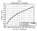
- FIG. 11A is a diagram illustrating an example of a rate distortion curve of an MPEG test sequence.
- FIG. 11B is a diagram showing another example of the rate distortion curve of the MPEG test sequence.
- the H.264 / AVC standard includes two types of filter methods (with the possibility of sending hints for post-filtering to a video decoding device according to a specific post-filtering method (SEI message as a hint for post-filtering) ( Specify interpolation filter and deblocking filter.
- SEI message as a hint for post-filtering
- Specify interpolation filter and deblocking filter The embodiments of the present invention described below show how to improve each of the above three methods by applying the present invention.
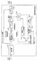
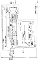
- FIG. 3A is a block diagram showing the video encoding device 100 according to the first embodiment of the present invention.
- FIG. 3B is a flowchart showing the operation of the moving picture coding apparatus 100 of FIG. 3A.
- the block diagram of FIG. 3A is similar to the conventional video encoding apparatus shown in FIG. 1, and like elements are given like reference numerals. Detailed description of similar elements is omitted.
- the moving image encoding apparatus 100 encodes a signal to be encoded constituting a moving image and outputs an encoded signal.
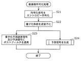
- the subtractor 110 subtracts the prediction signal from the encoding target signal to generate a prediction error signal (S11).
- the transform / quantization unit 120 quantizes the prediction error to generate a quantized coefficient (S12).
- the inverse quantization / inverse transform unit 130 inversely quantizes the quantization coefficient to generate a quantized prediction error signal (S13).
- the post filter design unit 138 ′ generates first filter information based on the encoding target signal and the prediction signal, and generates second filter information based on the encoding target signal and the quantized prediction error signal (S14). Then, post filter information including the first and second filter information is output.
- the entropy encoding unit 190 generates an encoded signal by entropy encoding the quantization coefficient, post filter information, and motion data described later (S15).
- the prediction signal generation unit 200 generates a prediction signal obtained by predicting the encoding target signal based on another encoding target signal encoded before the encoding target signal (input signal) (S16).
- the prediction signal generation unit 200 includes an adder 135, a deblocking filter 137, a memory 140, an in-screen frame prediction unit 150, a motion compensation prediction unit 160, an interpolation filter 162, a motion prediction unit 170, and an in-screen / inter-screen switch. 180.
- the prediction signal generation unit 200 forms a loop starting from the subtracter 110. Therefore, the filters (deblocking filter 137, interpolation filter 162, etc.) included in the prediction signal generation unit 200 are also called loop filters.
- the adder 135 adds the quantized prediction error signal and the prediction signal to generate a reconstructed signal.
- the deblocking filter 137 removes block distortion from the reconstructed signal and generates a decoded signal.
- the memory 140 functions as a delay device that temporarily stores the decoded signal.
- the intra-frame prediction unit 150 performs intra-screen prediction on the decoded signal to generate a prediction signal.
- the interpolation filter 162 spatially interpolates the pixel value of the decoded signal prior to motion compensation prediction.
- the motion prediction unit 170 performs motion prediction based on the decoded signal and the next encoding target signal, and generates motion data.
- the motion compensation prediction unit 160 performs motion compensation prediction based on the decoded signal and the motion data, and generates a prediction signal.
- the intra-screen / inter-screen switch 180 selects either the “in-screen” mode or the “inter-screen” mode as the prediction mode.
- the prediction signal output from the in-screen / inter-screen switch 180 is a signal obtained by predicting the next encoding target signal.
- the moving picture coding apparatus 100 is different from the conventional moving picture coding apparatus in the configuration of the post filter design unit 138 ′.
- the new post filter design unit 138 'receives the prediction signal and the quantized prediction error signal in addition to the encoding target signal.
- the new post filter design unit 138 ′ obtains optimum filter information for filtering the prediction signal and the quantized prediction error signal, the prediction signal and the quantized prediction error signal are different from each other.
- Statistical characteristics may be taken into account.
- the new post-filter design unit 138 ′ uses the cross-correlation between the quantized prediction error signal and the input signal to determine optimum filter information for each of the prediction signal and the quantized prediction error signal. Similar to the function, the autocorrelation function of each of the prediction signal and the quantized prediction error signal and the cross-correlation function of the prediction signal and the quantized prediction error signal may be calculated. That is, the new post filter design unit 138 ′ applies the Wiener method to determine the difference between the encoding target signal and the output of the new post filter 139 ′, that is, the filter information that minimizes the mean square error. May be. The determination result is supplied as post-filter information to the entropy encoding unit 190 and inserted into the encoded signal.
- the post-filter information includes a filter coefficient set for each of these two filters, an autocorrelation matrix coefficient and a cross-correlation vector, and other information for enabling the moving picture decoding apparatus 101 to set an appropriate filter.
- the autocorrelation function of the prediction signal and the quantized prediction error signal is calculated on the moving image decoding apparatus 101 side so that the cross-correlation function between these signals and the input signal only needs to be transmitted. Also good.
- the output of the new post filter 139 ′ may be expressed by the following equation 2.
- w 1, ⁇ , w M is, M prediction samples p 1, ⁇ ⁇ ⁇ ⁇ , a M filter coefficients of the first filter 139-1 applied to p M, w M + 1, ...., w M + N is, N prediction samples e 1 of the quantized prediction signal, ..., a N filter coefficients of the second filter 139-2 applied to e M.
- the filter coefficient that minimizes the mean square error between the desired signal s and the post-filter signal s ′ can be obtained by the following Equation 3 by applying the Wiener Hopf equation.
- the filter coefficients w 1 ,... W M + N are the autocorrelation of the prediction signal, the autocorrelation of the quantized prediction error signal, the cross correlation between the prediction signal and the quantized prediction error signal, and the prediction signal. And the desired signal, and the cross-correlation between the quantized prediction error signal and the desired signal.
- Equation 3 is a block diagonal determinant, and first and second filters 139-1 described later,
- the number of pieces of filter information 139-2 is obtained only by the autocorrelation of the prediction signal (quantized prediction error signal) and the cross-correlation between the prediction signal (quantized prediction error signal) and the desired signal.
- Equation 3 it is possible to derive a filter coefficient that minimizes noise according to two statistically different signals p and e.
- the maximum noise reduction performance can be obtained by reflecting the correlation and deriving the filter coefficient while maintaining the equation 3.
- the present invention is not limited to the filter coefficient calculation method described above. Numerical optimization may alternatively be performed to determine a filter coefficient that minimizes a predetermined measurement that indicates the difference between the filtered signal and the desired signal.
- the predetermined measurement value may be composed of, for example, a sum of absolute differences of weighted pixels.
- the weight of the pixel near the block boundary is made heavier than the pixel located at the center of the block.
- the new post filter design unit 138 ′ may receive the decoded signal, ie, the output of the deblocking filter 137, as an input (see the dotted line in FIG. 3A). In this way, the new post filter design unit 138 ′ may obtain filter information for a third filter 139-3, which will be described later, according to the statistical characteristics of the decoded signal and the input signal. This filter information is transmitted to the moving picture decoding apparatus 101 together with the filter information for the decoded signal and the quantized prediction error signal. Therefore, the moving picture decoding apparatus 101 may set the third filter 139-3 that operates directly on the decoded signal, as will be described in detail later with reference to FIG. 4A.
- the output of the novel post filter 139 ′ may be expressed as Equation 4 below, similar to Equation 2.
- w M + N + 1, ⁇ , w M + N + L is, L sample d 1 of the decoded signal, ⁇ ⁇ ⁇ , L filter of the third filter 139-3 that is applied to d L It is a coefficient.
- the filter coefficient that minimizes the mean square error between the desired signal s and the filtered signal s ′ can be obtained by the following equation (5).
- E [x i y i ] represents a sub-matrix composed of cross-correlation terms between x and y.
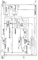
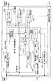
- FIG. 4A is a block diagram showing the video decoding device 101 according to the first embodiment of the present invention.
- FIG. 4B is a flowchart showing the operation of the moving picture decoding apparatus 101 in FIG. 4A.
- the block diagram of FIG. 4A is similar to the conventional video decoding device shown in FIG. 2, and like elements are given like reference numerals. Detailed description of similar elements is omitted.
- the moving picture decoding apparatus 101 decodes the encoded signal encoded by the moving picture encoding apparatus 100 shown in FIG. 3A to generate a decoded signal.
- the functional blocks common to the moving picture coding apparatus 100 shown in FIG. 3A are denoted by the same reference numerals, and detailed description thereof is omitted.
- the entropy decoding unit 191 performs entropy decoding on the encoded signal (input signal) output from the moving image encoding apparatus 100, and acquires quantization coefficients, post filter information, and motion data (S21).
- the inverse quantization / inverse transform unit 121 inversely quantizes the quantization coefficient to generate a quantized prediction error signal (S22).
- the post filter 139 ′ applies filter processing to each of the prediction signal and the quantized prediction error signal based on the post filter information (S23). Specifically, the prediction signal is filtered based on the first filter information to generate a filtered prediction signal, and the quantized prediction error signal is calculated based on the second filter information.
- a second filter 139-2 that generates a filtered quantized prediction error signal by filtering, and an adder 139-0 that adds the filtered predicted signal and the filtered quantized prediction error signal to generate a decoded signal With.
- the prediction signal generation unit 200 ′ generates a prediction signal obtained by predicting the decoded signal to be decoded next based on the decoded signal (S24).
- the prediction signal generation unit 200 ′ includes an adder 135, a deblocking filter 137, a memory 140, an in-screen frame prediction unit 150, a motion compensation prediction unit 160, an interpolation filter 162, and an in-screen / inter-screen switch 180.
- the difference from the prediction signal generation unit 200 shown in FIG. 3A is that the motion prediction unit 170 is omitted and motion data is acquired from the entropy decoding unit 191.
- the moving picture decoding apparatus 101 differs from the conventional moving picture decoding apparatus in the configuration of the post filter 139.
- the new processing filter 139 ′ is composed of at least two independent filters shown below.
- the first is a first filter 139-1 that filters a prediction signal that is an output from the intra-frame prediction unit 150 or the motion compensation prediction unit 160, and the second is an inverse quantization / inverse conversion unit 121.
- 2 is a second filter 139-2 for filtering the quantized prediction error signal that is an output from the first filter 139-2.
- the outputs of these filters are combined by an adder 139-0 and provided as the final output signal of the moving picture decoding apparatus 101.
- the new post filter 139 ′ receives post filter information derived from the input signal by the entropy decoding unit 191.
- the post-filter information includes at least two filters: a first filter 139-1 for the prediction signal and a second filter 139-1 for the quantized prediction error signal. Adopted to set and.
- the new post filter 139 ′ may include a third filter 139-3 that operates on the decoded signal output by the deblocking filter 137.
- the filter information given by the entropy decoding unit 191, that is, the decoded signal and the input signal specified on the video encoding device 100 side may be set according to the statistical characteristics of
- the post filter information includes filter coefficient sets of each filter, related autocorrelation matrix coefficients, cross-correlation vectors, and the moving picture decoding apparatus 101 as appropriate. You may comprise from the other information for enabling it to set a filter.
- post-filtering of decoded video information operates on at least two of the prediction signal, the quantized prediction error signal, and optionally the output of the deblocking filter. This is done using an independent optimization filter.
- the outputs of the first and second filters 193-1 and 193-2 are added.
- the third filter 193-3 is further provided, the addition result of the outputs of the first and second filters 193-1 and 193-3 and the output of the third filter 193-3 are averaged. You may make it do.
- each filter may be adapted to the statistical characteristics of the operating signal. As a result, the reconstruction error can be reduced more efficiently than when a single filter that operates only on the reconstructed signal is used.
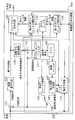
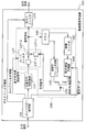
- FIG. 5 is a block diagram showing a video encoding apparatus 100 according to the second embodiment of the present invention.
- the block diagram of FIG. 5 is similar to the moving picture coding apparatus shown in FIG. 3A, and like reference numerals are given to like elements. Detailed description of similar elements is omitted.
- the moving picture coding apparatus 100 is different from the conventional moving picture coding apparatus in that it includes a post filter 139 and an additional second post filter design unit 138 ′. Moreover, it differs from the moving image encoding apparatus 100 shown by FIG. 3A by the point provided with the 1st post filter design part 138 and the post filter 139. Further, the second post filter design unit 138 ′ generates the third filter information based on the statistical characteristics of the output signal of the post filter 139 in addition to the functions of the post filter design unit 138 ′ shown in FIG. 3A. To do.
- the first post filter design unit 138 in FIG. 5 applies the first post filter 139 applied to the decoded signal output by the deblocking filter 137 of the video decoding device 101. Determine the optimal filter information.
- the post filter 139 is also a part of the moving picture coding apparatus 100 according to the second embodiment.
- the output of the post filter 139 is supplied to an additional second post filter design unit 138 ′ that receives the prediction signal, the quantized prediction error signal, and the input signal as inputs. Based on the statistical characteristics of the input signal, the additional second post-filter design unit 138 ′ operates on the prediction signal, the quantized prediction error signal, and the output signal of the post-filter 139, respectively. Identify filter information for the filtered filter. Therefore, the specified filter information is supplied to the entropy encoding unit 190 and inserted into the encoded signal.
- the additional second post filter design unit 138 ′ determines optimal filter information for each of the prediction signal, the quantized prediction error signal, and the output signal from the post filter 139. Therefore, the autocorrelation functions of the prediction signal, the quantized prediction error signal, and the output signal from the post filter 139 may be calculated in the same manner as the cross-correlation function between these signals and the input signal.
- the determination result is supplied to the entropy encoding unit 190 as additional post filter information, and is inserted into the encoded signal.
- the post filter information includes a filter coefficient set for each of these three filters, an autocorrelation matrix coefficient, a cross correlation vector, and other information for enabling the moving picture decoding apparatus 101 to set an appropriate filter. May be.
- the autocorrelation functions of the prediction signal, the quantized prediction error signal, and the output signal from the post filter 139 are calculated so that the cross-correlation function between these signals and the input signal only needs to be transmitted. It may be calculated on the moving image decoding apparatus 101 side.
- FIG. 6 is a block diagram showing a moving picture decoding apparatus 101 according to the second embodiment of the present invention.
- the block diagram of FIG. 6 is similar to the moving picture decoding apparatus 101 shown in FIG. 4A, and the same reference numerals are given to the same elements. Detailed description of similar elements is omitted.
- the moving picture decoding apparatus 101 receives an additional second signal that receives a prediction signal, a quantized prediction error signal, and an output signal from the first post filter 139 as inputs. It differs from the conventional video decoding device in that it includes a post filter 139 ′. Moreover, it is different from the moving picture decoding apparatus 101 shown in FIG. 4A in that the first post filter 139 is provided.
- the additional second post filter 139 ′ is composed of the following three independent filters.
- the first is a first filter 139-1 that filters a prediction signal that is an output from the intra-frame prediction unit 150 or the motion compensation prediction unit 160
- the second is an inverse quantization / inverse conversion unit 121.
- the third filter 139-2 that filters the quantized prediction error signal that is an output from the first post filter 139-2
- the third filter 139 that filters the post filter signal that is the output from the first post filter 139. -3.
- the addition result of the outputs of the first and second filters 139-1 and 139-2 and the output of the third filter 139-3 are averaged and provided as the final output signal of the decoding apparatus 101.
- the post filter information includes a filter coefficient set of each filter, an associated autocorrelation matrix coefficient, a cross-correlation vector, and an appropriate filter set by the decoding apparatus. It may be composed of other information for making it possible.
- post-filtering of decoded video information operates on the prediction signal, the quantized prediction error signal, and the output of the (conventional) post-filter individually or simultaneously optimally
- This is done using a simplified filter.
- the outputs of these separate filters are added.
- Each filter may be adapted to the statistical characteristics of the operating signal. In this way, reconstruction errors can be reduced more efficiently than using a single filter that operates only on the reconstructed signal.
- the encoded signal generated by the video encoding device 100 of the present embodiment is compatible with a conventional video decoding device that may simply ignore additional post filter information.
- the video decoding apparatus 101 that has recognized the additional post filtering may employ information for setting an additional post filter in order to further improve the image quality.
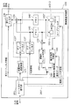
- FIG. 7 is a block diagram showing a video encoding apparatus 100 according to the third embodiment of the present invention.
- the block diagram of FIG. 7 is similar to the moving picture encoding apparatus 100 shown in FIG. 3A, and the same reference numerals are given to the same elements. Detailed description of similar elements is omitted.
- the moving picture coding apparatus 100 includes a new loop filter design unit 138 ′′ corresponding to a new loop filter 137 ′ instead of the adder 135 and the deblocking filter 137. It is different from the conventional video encoding device and the video encoding device 100 shown in FIG. However, the post filter design unit 138 ′ shown in FIG. 3A and the loop filter design unit 138 ′′ shown in FIG. 7 use the generated filter information in the post filter 139 ′ or the loop filter 137 ′. Although it differs, the filter information generation process itself is common.
- the new loop filter design unit 138 ′′ receives an input signal, a prediction signal, and a quantized prediction error signal as inputs. Similar to the new post filter design unit 138 ′ of the first embodiment, the new loop filter design unit 138 ′′ analyzes the statistical characteristics of the input signal and uses the new loop filter information as a new loop filter. 137 ′ and the entropy encoding unit 190.
- the new loop filter 137 ′ includes a first filter 137-1 that operates on the prediction signal, a second filter 137-2 that operates on the quantized prediction error signal, and for adding these filter signals. And an adder 137-0.
- the first filter 137-1 and the second filter 137-2 are set according to the new loop filter information received from the new loop filter design unit 138 ′′, as described in the above embodiment. .
- the mean square error between the first filter 137-1 and the second filter 137-2 between the signal to be encoded and the reconstructed signal that is the output of the new loop filter 137 ′ is also possible to optimize so that the difference measurement value such as the above is minimized.
- the new loop filter 137 operates as an appropriate loop filter (both filters operate on all pixels in a block) or a deblocking filter (especially for pixels near the block boundary). Whether both filters operate intensively) depends on how the first and second filters 137-1 and 137-2 are set. Particularly in the former case, the moving picture coding apparatus 100 may additionally include a conventional deblocking filter (not shown).
- the deblocking filter receives an input from the new loop filter 137 ′ and outputs the output to the storage unit 140 and the post filter design unit 138.
- FIG. 8 is a block diagram showing a moving picture decoding apparatus 101 according to the third embodiment of the present invention.
- the block diagram of FIG. 8 is similar to the moving picture decoding apparatus 101 shown in FIG. 4A, and the same reference numerals are given to the same elements. Detailed description of similar elements is omitted.
- the moving picture decoding apparatus 101 is provided with a conventional moving picture decoding apparatus and FIG. 4A in that it includes an adder 135 and a novel loop filter 137 ′ replacing the conventional deblocking filter 137. It differs from the moving picture decoding apparatus 101 shown.
- the configuration of the new loop filter 137 ′ is the same as the configuration of the corresponding moving image encoding device 100 shown in FIG. More specifically, the novel loop filter 137 ′ includes a first filter 137-1 that operates on the prediction signal, a second filter 137-2 that operates on the quantized prediction error signal, and those filtered An adder 137-0 for adding signals is included.
- the first filter 137-1 and the second filter 137-2 are set according to the new loop filter information received from the entropy decoding unit 191 as described in the above embodiment.
- the new loop filter 137 ′ of the moving picture decoding apparatus 101 may be followed by a conventional deblocking filter (not shown).
- an adaptive loop filter 137 ' is provided that consists of two simultaneously or individually optimized filters that operate on each of the prediction signal and the quantized prediction error signal.
- the loop filter 137 ′ may take into account different statistical characteristics of these signals.
- the reconstruction error can be reduced more efficiently than when a single filter that operates only on the reconstructed signal is used.
- the coding efficiency is improved by reducing the reconstruction error.
- FIG. 9 is a block diagram showing a video encoding apparatus 100 according to the fourth embodiment of the present invention.
- the block diagram of FIG. 9 is similar to the moving picture coding apparatus 100 shown in FIG. 3A, and like reference numerals are given to like elements. Detailed description of similar elements is omitted.
- the present invention is applied to adaptive interpolation filtering for motion compensation prediction.
- the video encoding apparatus 100 according to the present embodiment is different from the conventional video encoding apparatus and the video encoding apparatus 100 shown in FIG. 3A in the following points. That is, a new loop filter and design unit 162 ′ are provided in place of the interpolation filter 162, and two deblocking filters 137, 137 are used to separately deblock the prediction signal and the quantized prediction error signal.
- the storage unit 140 and 140 ′ are also provided for storing the prediction signal and the quantized prediction error signal separately.
- the memory 140 ′ for storing the quantized prediction error is larger than the memory 140 for storing the predicted signal. It may have a high bit depth. In order to reduce the bit depth, it may be beneficial to reduce the dynamic range of the quantized prediction error signal. This is also possible if additional quantization is performed on the quantized prediction signal.
- the new loop filter and design unit 162 ′ of FIG. 9 operates on the first filter 162-1 that operates on the prediction signal delayed by the storage unit 140 and the quantization error signal delayed by the storage unit 140 ′.
- the second filter 162-2 operates, and an adder 162-0 for adding these two filter signals.
- the first and second filters 162-1 and 162-2 are optimized so as to minimize the measurement distance between the output of the adder 162-0 and the desired signal.
- the desired signal is an input signal at a different time.
- the result of the optimization process is supplied to the entropy encoding unit 190 as new interpolation filter information and inserted as an output signal.
- FIG. 10 is a block diagram showing a moving picture decoding apparatus 101 according to the fourth embodiment of the present invention.
- the block diagram of FIG. 10 is similar to the moving picture decoding apparatus 101 shown in FIG. 4A, and the same reference numerals are given to the same elements. Detailed description of similar elements is omitted.
- the video decoding device 101 according to the fourth embodiment of the present invention is different from the conventional video decoding device and the video decoding device 101 shown in FIG. 4A in the following points. That is, a new loop filter 162 ′′ is provided in place of the interpolation filter 162, and two deblocking filters 137, 137 ′′ are used to separately deblock the prediction signal and the quantized prediction error signal. Is different in that two storage units 140 and 140 ′ are provided to store the prediction signal and the quantized prediction error signal separately.
- the video decoding device 101 including the novel loop filter 162 ′′ includes the first filter 162-1 that operates on the prediction signal, And a second filter 162-2 that operates on the quantized prediction error signal, and an adder 162-0 for adding these filtered signals.
- the first and second filters 162-1 and 162-2 are set according to the new interpolation filter information received from the entropy decoding unit 191 as described in the above embodiment.
- an adaptive interpolation filter for performing motion compensation prediction with decimal pixel accuracy is provided.
- the loop filter 162 ′′ of the present invention is composed of two filters, which are optimized simultaneously or individually, each operating on a (delayed) prediction signal and a (delayed) quantized prediction signal. In this way, the loop filter 162 '' may take into account different statistical characteristics of these signals. As a result, the prediction error can be reduced more efficiently than when the conventional adaptive interpolation filter 162 that operates only on the (delayed) decoded signal is used. Therefore, encoding efficiency can be improved similarly.
- Y-PSNR which is a luminance component with respect to the bit rate of two types of MPEG test sequences, is represented by a point on the graph.
- the method of the present invention uses a non-separable two-dimensional Wiener post filter having a coefficient of 5 ⁇ 5. H.264 / AVC. Intra-screen coding is applied for comparison. An increase in Y-PSNR up to 0.3 dB can be observed in the present invention.
- the moving image filter of the present invention includes filters that operate on the prediction signal and the quantized prediction error signal, respectively.
- each signal pair selected from the set of the prediction signal, the error signal, and the reconstructed signal (a sum of the prediction signal and the error signal) is linearly independent. Therefore, the present invention may be applied to any one of the combination of the reconstructed signal and the quantized prediction error signal and the combination of the reconstructed signal and the predicted signal.
- the present invention is not limited by whether the filter is fixed or adaptive. Any of the filters in the filtering method of the present invention may include a fixed filter or an adaptive filter.
- filter information such as coefficients is encoded and transmitted as auxiliary information to a video decoding device.
- H. In the H.264 / AVC encoding method, filter information such as coefficients is inserted into a slice header, a picture parameter set, or a sequence parameter set and transmitted.
- the post filter information may be transmitted to the video decoding device as supplementary extension information (SEI).
- SEI supplementary extension information
- the present invention can be applied to any of conventional encoding methods based on differential pulse code modulation including a method for encoding moving images and non-moving images, that is, audio data.
- H.C. The present invention may be applied to a H.264 / AVC spatial scalable video coding method.
- H. In this method in H.264 / AVC, a low spatial resolution reconstructed image composed of a prediction signal and a quantized prediction error signal is up-sampled and interpolated by a filter to obtain a high spatial resolution image.
- a prediction signal and a quantized prediction error signal can be considered separately by using different filter coefficients for each signal.
- the present invention can also be applied to high frequency modeling. In that case, the present invention makes it possible to utilize the statistical characteristics of the prediction signal and the quantized prediction error signal for the purpose of filtering and adjusting higher-order statistical characteristics.
- the present invention is not limited to the Wiener filter.
- the present invention may be applied to other adaptive filters such as a nonlinear adaptive filter based on Volterra series expansion, a filter that optimizes a measurement value other than a mean square error between a corrupted signal and a desired signal, and the like. .
- the other two individually optimized filters are loop filters according to the third embodiment. It may be adopted.
- Other embodiments can be combined in a similar manner.
- the present invention relates to an optimum filter in moving picture coding based on differential pulse code modulation.
- the method according to the present invention is not a single filter that operates on the reconstructed signal that is the result of adding the prediction signal and the error signal, but two filters that operate independently on the prediction signal and the quantized prediction error signal. Is to provide.
- the prediction error and / or the reconstruction error can be reduced, and as a result, the coding efficiency can be improved.
- Each of the above devices is specifically a computer system including a microprocessor, ROM, RAM, a hard disk unit, a display unit, a keyboard, a mouse, and the like.
- a computer program is stored in the RAM or hard disk unit.
- Each device achieves its functions by the microprocessor operating according to the computer program.
- the computer program is configured by combining a plurality of instruction codes indicating instructions for the computer in order to achieve a predetermined function.
- the system LSI is an ultra-multifunctional LSI manufactured by integrating a plurality of component parts on one chip, and specifically, a computer system including a microprocessor, a ROM, a RAM, and the like. is there. A computer program is stored in the RAM. The system LSI achieves its functions by the microprocessor operating according to the computer program.
- each of the above devices may be constituted by an IC card or a single module that can be attached to and detached from each device.
- the IC card or the module is a computer system including a microprocessor, a ROM, a RAM, and the like.
- the IC card or the module may include the super multifunctional LSI described above.
- the IC card or the module achieves its function by the microprocessor operating according to the computer program. This IC card or this module may have tamper resistance.
- the present invention may be the method described above. Further, the present invention may be a computer program that realizes these methods by a computer, or may be a digital signal composed of the computer program.
- the present invention also provides a computer-readable recording medium such as a flexible disk, hard disk, CD-ROM, MO, DVD, DVD-ROM, DVD-RAM, BD (Blu-ray Disc). ), Recorded in a semiconductor memory or the like.
- the digital signal may be recorded on these recording media.
- the computer program or the digital signal may be transmitted via an electric communication line, a wireless or wired communication line, a network represented by the Internet, a data broadcast, or the like.
- the present invention may be a computer system including a microprocessor and a memory, the memory storing the computer program, and the microprocessor operating according to the computer program.
- the program or the digital signal is recorded on the recording medium and transferred, or the program or the digital signal is transferred via the network or the like, and executed by another independent computer system. It is good.
- the present invention is advantageously used for a moving picture encoding method (apparatus) and a moving picture decoding method (apparatus).
Landscapes
- Engineering & Computer Science (AREA)
- Multimedia (AREA)
- Signal Processing (AREA)
- Compression Or Coding Systems Of Tv Signals (AREA)
Abstract
Description
(a)独立した動画像フレームのそれぞれに対して、ブロックレベルでそのデータの圧縮をおこなうために、各動画像フレームを2次元の画素ブロックに分割するステージ
(b)各ブロックに対して時空間予測方法を適用し、空間ドメインにおける予測誤差を周波数ドメインに変換することによって、時空間動画像情報を無相関化して係数を取得するステージ
(c)得られた係数を量子化することによって、総データ量を削減するステージ
(d)量子化係数と予測パラメータとを、エントロピー符号化アルゴリズムを用いて符号化することによって、残りのデータを圧縮するステージ
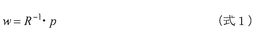
図3Aは、本発明の第1の実施形態に係る動画像符号化装置100を示すブロック図である。図3Bは、図3Aの動画像符号化装置100の動作を示すフローチャートである。図3Aのブロック図は、図1に示される従来の動画像符号化装置に類似しており、同様の要素には同様の参照符号が付されている。類似要素については、詳細な説明を省略する。

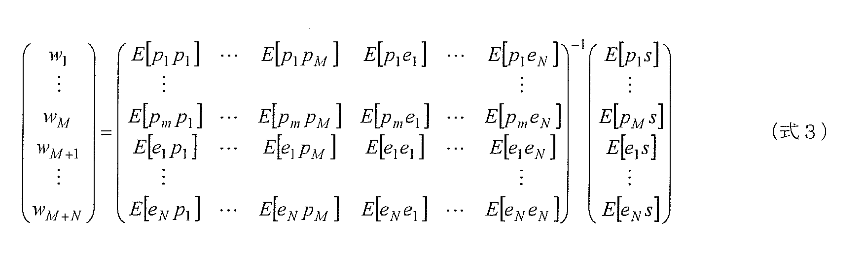


図5は、本発明の第2の実施形態に係る動画像符号化装置100を示すブロック図である。図5のブロック図は、図3Aに示される動画像符号化装置に類似しており、同様の要素には同様の参照符号が付されている。類似要素については、詳細な説明を省略する。
図7は、本発明の第3の実施形態に係る動画像符号化装置100を示すブロック図である。図7のブロック図は、図3Aに示される動画像符号化装置100に類似しており、同様の要素には同様の参照符号が付されている。類似要素については、詳細な説明を省略する。
図9は、本発明の第4の実施形態に係る動画像符号化装置100を示すブロック図である。図9のブロック図は、図3Aに示される動画像符号化装置100に類似しており、同様の要素には同様の参照符号が付されている。類似要素については、詳細な説明を省略する。
なお、本発明を上記各実施の形態1~4に基づいて説明してきたが、本発明は、上記の各実施の形態1~4に限定されないのはもちろんである。以下のような場合も本発明に含まれる。
101 動画像復号装置
110 減算器
120 変換・量子化部
121,130 逆量子化・逆変換部
135,135´,137-0,139-0,162-0 加算器
137,137´´ デブロッキングフィルタ
137´,162´´ ループフィルタ
137-1,137-2,139-1,139-2,139-3,162-1,162-2 フィルタ
138,138´ ポストフィルタ設計部
138´´ ループフィルタ設計部
139,139´ ポストフィルタ
140,140´ メモリ
150 画面内フレーム予測部
160 動き補償予測部
162 補間フィルタ
162´ ループフィルタおよび設計部
170 動き予測部
180 画面内/画面間スイッチ
190 エントロピー符号化部
191 エントロピー復号部
200,200´ 予測信号生成部
Claims (14)
- 動画像を構成する符号化対象信号を符号化する動画像符号化方法であって、
前記符号化対象信号より前に符号化された他の符号化対象信号に基づいて、前記符号化対象信号を予測した予測信号を生成する予測信号生成ステップと、
前記符号化対象信号から前記予測信号を減算して得られる予測誤差を量子化して量子化係数を生成する量子化ステップと、
前記量子化係数を逆量子化して量子化予測誤差信号を生成する逆量子化ステップと、
前記予測信号及び前記量子化予測誤差信号のうち、前記予測信号のみの統計的特性に基づいて第1のフィルタ情報を生成すると共に、前記量子化予測誤差信号のみの統計的特性に基づいて第2のフィルタ情報を生成するフィルタ情報生成ステップと、
前記量子化ステップにおいて生成される前記量子化係数と、前記フィルタ情報生成ステップにおいて生成される前記第1及び第2のフィルタ情報とをエントロピー符号化して符号化信号を生成するエントロピー符号化ステップとを含む
動画像符号化方法。 - 前記フィルタ情報生成ステップでは、前記第1のフィルタ情報に基づいて前記予測信号をフィルタ処理して得られるフィルタリング済み予測信号、及び前記第2のフィルタ情報に基づいて前記量子化予測誤差信号をフィルタ処理して得られるフィルタリング済み量子化予測誤差信号を加算して得られる再構築信号と、前記符号化対象信号との差分が最小化されるように、前記第1及び第2のフィルタ情報を生成する
請求項1に記載の動画像符号化方法。 - 前記予測信号生成ステップは、
前記第1のフィルタ情報に基づいて前記予測信号をフィルタ処理してフィルタリング済み予測信号を生成し、前記第2のフィルタ情報に基づいて前記量子化予測誤差信号をフィルタ処理してフィルタリング済み量子化予測誤差信号を生成し、前記フィルタリング済み予測信号及び前記フィルタリング済み量子化予測誤差信号を加算して再構築信号を生成するフィルタリングステップと、
前記再構築信号に基づいて、前記符号化対象信号より後に符号化される他の符号化対象信号を予測した第2の予測信号を生成する予測信号生成ステップとを含む
請求項1に記載の動画像符号化方法。 - 前記フィルタリングステップでは、前記再構築信号のブロック歪みを減少させるデブロック処理をする
請求項3に記載の動画像符号化方法。 - 前記フィルタリングステップでは、動き補償予測に先立って行われる補間フィルタリング処理をする
請求項3に記載の動画像符号化方法。 - 前記フィルタ情報生成ステップでは、前記予測信号と前記量子化予測誤差信号とを加算して得られる再構築信号の統計的特性に基づいて第3のフィルタ情報を生成し、
前記エントロピー符号化ステップでは、前記量子化予測誤差信号と、前記第1、第2、及び第3のフィルタ情報とをエントロピー符号化して前記符号化信号を生成する
請求項1に記載の動画像符号化方法。 - 動画像を構成する符号化信号を復号して復号信号を生成する動画像復号方法であって、
前記符号化信号をエントロピー復号して量子化係数と、第1及び第2のフィルタ情報とを取得するエントロピー復号ステップと、
前記量子化係数を逆量子化して量子化予測誤差信号を生成する逆量子化ステップと、
前記符号化信号より前に復号された他の符号化信号に基づいて、前記復号信号を予測した予測信号を生成する予測信号生成ステップと、
前記第1のフィルタ情報に基づいて前記予測信号をフィルタ処理してフィルタリング済み予測信号を生成し、前記第2のフィルタ情報に基づいて前記量子化予測誤差信号をフィルタ処理してフィルタリング済み量子化予測誤差信号を生成し、前記フィルタリング済み予測信号及び前記フィルタリング済み量子化予測誤差信号を加算して前記復号信号を生成するフィルタリングステップを含む
動画像復号方法。 - 前記予測信号生成ステップは、
前記第1のフィルタ情報に基づいて前記予測信号をフィルタ処理してフィルタリング済み予測信号を生成し、前記第2のフィルタ情報に基づいて前記量子化予測誤差信号をフィルタ処理してフィルタリング済み量子化予測誤差信号を生成し、前記フィルタリング済み予測信号及び前記フィルタリング済み量子化予測誤差信号を加算して再構築信号を生成するフィルタリングステップと、
前記再構築信号に基づいて、前記符号化信号より後に復号される他の復号信号を予測した第2の予測信号を生成する予測信号生成ステップとを含む
請求項7に記載の動画像復号方法。 - 動画像を構成する符号化対象信号を符号化する動画像符号化装置であって、
前記符号化対象信号より前に符号化された他の符号化対象信号に基づいて、前記符号化対象信号を予測した予測信号を生成する予測信号生成部と、
前記符号化対象信号から前記予測信号を減算して得られる予測誤差を量子化して量子化係数を生成する量子化部と、
前記量子化係数を逆量子化して量子化予測誤差信号を生成する逆量子化部と、
前記予測信号及び前記量子化予測誤差信号のうち、前記予測信号のみの統計的特性に基づいて第1のフィルタ情報を生成すると共に、前記量子化予測誤差信号のみの統計的特性に基づいて第2のフィルタ情報を生成するフィルタ情報生成部と、
前記量子化部で生成される前記量子化係数と、前記フィルタ情報生成部で生成される前記第1及び第2のフィルタ情報とをエントロピー符号化して符号化信号を生成するエントロピー符号化部とを備える
動画像符号化装置。 - 動画像を構成する符号化信号を復号して復号信号を生成する動画像復号装置であって、
前記符号化信号をエントロピー復号して量子化係数と、第1及び第2のフィルタ情報とを取得するエントロピー復号部と、
前記量子化係数を逆量子化して量子化予測誤差信号を生成する逆量子化部と、
前記符号化信号より前に復号された他の符号化信号に基づいて、前記復号信号を予測した予測信号を生成する予測信号生成部と、
前記第1のフィルタ情報に基づいて前記予測信号をフィルタ処理してフィルタリング済み予測信号を生成し、前記第2のフィルタ情報に基づいて前記量子化予測誤差信号をフィルタ処理してフィルタリング済み量子化予測誤差信号を生成し、前記フィルタリング済み予測信号及び前記フィルタリング済み量子化予測誤差信号を加算して前記復号信号を生成するフィルタリング部とを備える
動画像復号装置。 - コンピュータに、動画像を構成する符号化対象信号を符号化させるプログラムであって、
前記符号化対象信号より前に符号化された他の符号化対象信号に基づいて、前記符号化対象信号を予測した予測信号を生成する予測信号生成ステップと、
前記符号化対象信号から前記予測信号を減算して得られる予測誤差を量子化して量子化係数を生成する量子化ステップと、
前記量子化係数を逆量子化して量子化予測誤差信号を生成する逆量子化ステップと、
前記予測信号及び前記量子化予測誤差信号のうち、前記予測信号のみの統計的特性に基づいて第1のフィルタ情報を生成すると共に、前記量子化予測誤差信号のみの統計的特性に基づいて第2のフィルタ情報を生成するフィルタ情報生成ステップと、
前記量子化ステップにおいて生成される前記量子化係数と、前記フィルタ情報生成ステップにおいて生成される前記第1及び第2のフィルタ情報とをエントロピー符号化して符号化信号を生成するエントロピー符号化ステップとを含む
プログラム。 - コンピュータに、動画像を構成する符号化信号を復号して復号信号を生成させるプログラムであって、
前記符号化信号をエントロピー復号して量子化係数と、第1及び第2のフィルタ情報とを取得するエントロピー復号ステップと、
前記量子化係数を逆量子化して量子化予測誤差信号を生成する逆量子化ステップと、
前記符号化信号より前に復号された他の符号化信号に基づいて、前記復号信号を予測した予測信号を生成する予測信号生成ステップと、
前記第1のフィルタ情報に基づいて前記予測信号をフィルタ処理してフィルタリング済み予測信号を生成し、前記第2のフィルタ情報に基づいて前記量子化予測誤差信号をフィルタ処理してフィルタリング済み量子化予測誤差信号を生成し、前記フィルタリング済み予測信号及び前記フィルタリング済み量子化予測誤差信号を加算して前記復号信号を生成するフィルタリングステップを含む
プログラム。 - 動画像を構成する符号化対象信号を符号化する集積回路であって、
前記符号化対象信号より前に符号化された他の符号化対象信号に基づいて、前記符号化対象信号を予測した予測信号を生成する予測信号生成部と、
前記符号化対象信号から前記予測信号を減算して得られる予測誤差を量子化して量子化係数を生成する量子化部と、
前記量子化係数を逆量子化して量子化予測誤差信号を生成する逆量子化部と、
前記予測信号及び前記量子化予測誤差信号のうち、前記予測信号のみの統計的特性に基づいて第1のフィルタ情報を生成すると共に、前記量子化予測誤差信号のみの統計的特性に基づいて第2のフィルタ情報を生成するフィルタ情報生成部と、
前記量子化部で生成される前記量子化係数と、前記フィルタ情報生成部で生成される前記第1及び第2のフィルタ情報とをエントロピー符号化して符号化信号を生成するエントロピー符号化部とを備える
集積回路。 - 動画像を構成する符号化信号を復号して復号信号を生成する集積回路であって、
前記符号化信号をエントロピー復号して量子化係数と、第1及び第2のフィルタ情報とを取得するエントロピー復号部と、
前記量子化係数を逆量子化して量子化予測誤差信号を生成する逆量子化部と、
前記符号化信号より前に復号された他の符号化信号に基づいて、前記復号信号を予測した予測信号を生成する予測信号生成部と、
前記第1のフィルタ情報に基づいて前記予測信号をフィルタ処理してフィルタリング済み予測信号を生成し、前記第2のフィルタ情報に基づいて前記量子化予測誤差信号をフィルタ処理してフィルタリング済み量子化予測誤差信号を生成し、前記フィルタリング済み予測信号及び前記フィルタリング済み量子化予測誤差信号を加算して前記復号信号を生成するフィルタリング部とを備える
集積回路。
Priority Applications (5)
| Application Number | Priority Date | Filing Date | Title |
|---|---|---|---|
| EP09773192A EP2323407A4 (en) | 2008-07-03 | 2009-07-02 | VIDEO IMAGE CODING METHOD, VIDEO IMAGE DECODING METHOD, VIDEO IMAGE CODING DEVICE, VIDEO IMAGE DECODING DEVICE, PROGRAM AND INTEGRATED CIRCUIT |
| CN200980100297A CN101796847A (zh) | 2008-07-03 | 2009-07-02 | 运动图像编码方法、运动图像解码方法、运动图像编码装置、运动图像解码装置、程序以及集成电路 |
| US12/675,563 US20100254450A1 (en) | 2008-07-03 | 2009-07-02 | Video coding method, video decoding method, video coding apparatus, video decoding apparatus, and corresponding program and integrated circuit |
| BRPI0904619-4A BRPI0904619A2 (pt) | 2008-07-03 | 2009-07-02 | Método de codificação de vídeo, método de decodificação de vídeo, aparelho de codificação de vídeo, aparelho de decodificação de vídeo e programa e circuito integrado correspondentes |
| JP2010504332A JPWO2010001614A1 (ja) | 2008-07-03 | 2009-07-02 | 動画像符号化方法、動画像復号方法、動画像符号化装置、動画像復号装置、プログラム、及び集積回路 |
Applications Claiming Priority (2)
| Application Number | Priority Date | Filing Date | Title |
|---|---|---|---|
| EP08012036.3 | 2008-07-03 | ||
| EP08012036A EP2141927A1 (en) | 2008-07-03 | 2008-07-03 | Filters for video coding |
Publications (1)
| Publication Number | Publication Date |
|---|---|
| WO2010001614A1 true WO2010001614A1 (ja) | 2010-01-07 |
Family
ID=39927590
Family Applications (1)
| Application Number | Title | Priority Date | Filing Date |
|---|---|---|---|
| PCT/JP2009/003086 Ceased WO2010001614A1 (ja) | 2008-07-03 | 2009-07-02 | 動画像符号化方法、動画像復号方法、動画像符号化装置、動画像復号装置、プログラム、及び集積回路 |
Country Status (9)
| Country | Link |
|---|---|
| US (1) | US20100254450A1 (ja) |
| EP (2) | EP2141927A1 (ja) |
| JP (1) | JPWO2010001614A1 (ja) |
| KR (1) | KR20110039511A (ja) |
| CN (1) | CN101796847A (ja) |
| BR (1) | BRPI0904619A2 (ja) |
| RU (1) | RU2010107598A (ja) |
| TW (1) | TW201008290A (ja) |
| WO (1) | WO2010001614A1 (ja) |
Cited By (10)
| Publication number | Priority date | Publication date | Assignee | Title |
|---|---|---|---|---|
| WO2012008506A1 (ja) * | 2010-07-15 | 2012-01-19 | シャープ株式会社 | 画像フィルタ装置、復号装置、動画像復号装置、符号化装置、動画像符号化装置、および、データ構造 |
| WO2012063878A1 (ja) * | 2010-11-10 | 2012-05-18 | ソニー株式会社 | 画像処理装置と画像処理方法 |
| JP2012186573A (ja) * | 2011-03-04 | 2012-09-27 | Kddi Corp | 動画像符号化装置、動画像符号化方法、およびプログラム |
| WO2013001720A1 (ja) * | 2011-06-30 | 2013-01-03 | 三菱電機株式会社 | 画像符号化装置、画像復号装置、画像符号化方法及び画像復号方法 |
| JP2013529875A (ja) * | 2010-06-25 | 2013-07-22 | クゥアルコム・インコーポレイテッド | 圧縮ビットストリームへの交換補間フィルタ係数の組み込み |
| JP2013539287A (ja) * | 2010-09-01 | 2013-10-17 | クゥアルコム・インコーポレイテッド | 和修正ラプラシアンフィルタ索引付けと4分木区分との組合せに基づくマルチ入力適応フィルタ |
| JP2013229768A (ja) * | 2012-04-25 | 2013-11-07 | Nippon Telegr & Teleph Corp <Ntt> | 映像符号化方法及び装置 |
| JP2014506065A (ja) * | 2011-01-05 | 2014-03-06 | クゥアルコム・インコーポレイテッド | 1次元スイッチ式フィルタと1次元適応フィルタとの組合せを使用したビデオフィルタリング |
| TWI603612B (zh) * | 2010-09-30 | 2017-10-21 | 三菱電機股份有限公司 | 畫像編碼裝置、畫像解碼裝置、畫像編碼方法、畫像解碼方法及資料結構 |
| US9819966B2 (en) | 2010-09-01 | 2017-11-14 | Qualcomm Incorporated | Filter description signaling for multi-filter adaptive filtering |
Families Citing this family (25)
| Publication number | Priority date | Publication date | Assignee | Title |
|---|---|---|---|---|
| EP1944974A1 (en) * | 2007-01-09 | 2008-07-16 | Matsushita Electric Industrial Co., Ltd. | Position dependent post-filter hints |
| EP2192786A1 (en) * | 2008-11-27 | 2010-06-02 | Panasonic Corporation | Frequency domain filters for video coding |
| EP2375745A1 (en) | 2010-04-12 | 2011-10-12 | Panasonic Corporation | Efficient storing of picture representation using adaptive non-uniform quantizer |
| EP2375747B1 (en) | 2010-04-12 | 2019-03-13 | Sun Patent Trust | Filter positioning and selection |
| DK3457689T3 (da) * | 2010-05-25 | 2020-10-12 | Lg Electronics Inc | Ny planar forudsigelsestilstand |
| WO2012013327A1 (en) | 2010-07-26 | 2012-02-02 | Panasonic Corporation | Quantized prediction error signal for three-input-wiener-filter |
| JP5066232B2 (ja) * | 2010-07-28 | 2012-11-07 | 株式会社東芝 | 情報処理装置および画像処理方法 |
| WO2012025215A1 (en) | 2010-08-23 | 2012-03-01 | Panasonic Corporation | Adaptive golomb codes to code filter coefficients |
| RU2562432C2 (ru) | 2010-11-26 | 2015-09-10 | Нек Корпорейшн | Устройство видеокодирования, устройство видеодекодирования, способ видеокодирования, способ видеодекодирования и программа |
| KR20120068743A (ko) | 2010-12-17 | 2012-06-27 | 한국전자통신연구원 | 인터 예측 방법 및 그 장치 |
| JP6056122B2 (ja) * | 2011-01-24 | 2017-01-11 | ソニー株式会社 | 画像符号化装置と画像復号装置およびその方法とプログラム |
| JP5552093B2 (ja) * | 2011-06-13 | 2014-07-16 | 日本電信電話株式会社 | 動画像符号化装置、動画像符号化方法及び動画像符号化プログラム |
| KR101442127B1 (ko) * | 2011-06-21 | 2014-09-25 | 인텔렉추얼디스커버리 주식회사 | 쿼드트리 구조 기반의 적응적 양자화 파라미터 부호화 및 복호화 방법 및 장치 |
| US20130163660A1 (en) * | 2011-07-01 | 2013-06-27 | Vidyo Inc. | Loop Filter Techniques for Cross-Layer prediction |
| TWI577191B (zh) * | 2011-11-03 | 2017-04-01 | 太陽專利信託 | 以脈衝碼調變模式編碼之區塊的濾波技術 |
| WO2013074365A1 (en) * | 2011-11-18 | 2013-05-23 | Dolby Laboratories Licensing Corporation | Subjective based post-filter optimization |
| WO2014010584A1 (ja) * | 2012-07-09 | 2014-01-16 | 日本電信電話株式会社 | 画像符号化方法、画像復号方法、画像符号化装置、画像復号装置、画像符号化プログラム、画像復号プログラム及び記録媒体 |
| GB2506593B (en) * | 2012-09-28 | 2017-03-22 | Canon Kk | Methods for encoding image data, methods for decoding image data and methods for post-filtering reconstructed image data and corresponding devices |
| EP3349450B1 (en) * | 2015-09-08 | 2021-08-25 | LG Electronics Inc. | Method for image decoding and apparatus therefor |
| EP3220643A1 (en) | 2016-03-14 | 2017-09-20 | Thomson Licensing | Method and device for encoding at least one image unit, and method and device for decoding a stream representative of at least one image unit |
| CN113196777B (zh) * | 2018-12-17 | 2024-04-19 | 北京字节跳动网络技术有限公司 | 用于运动补偿的参考像素填充 |
| US10985951B2 (en) | 2019-03-15 | 2021-04-20 | The Research Foundation for the State University | Integrating Volterra series model and deep neural networks to equalize nonlinear power amplifiers |
| WO2020213945A1 (ko) | 2019-04-16 | 2020-10-22 | 엘지전자 주식회사 | 인트라 예측 기반 영상 코딩에서의 변환 |
| CN120752913A (zh) * | 2023-03-01 | 2025-10-03 | 高通股份有限公司 | 视频译码中用于自适应环路滤波器的输入数据的预处理 |
| US20240297989A1 (en) * | 2023-03-01 | 2024-09-05 | Qualcomm Incorporated | Preprocessing of input data for adaptive loop filter in video coding |
Citations (6)
| Publication number | Priority date | Publication date | Assignee | Title |
|---|---|---|---|---|
| JPH08251418A (ja) * | 1995-03-10 | 1996-09-27 | Kawasaki Steel Corp | ブロック歪低減装置および低減方法 |
| JPH1070717A (ja) * | 1996-06-19 | 1998-03-10 | Matsushita Electric Ind Co Ltd | 画像符号化装置及び画像復号化装置 |
| JPH10150663A (ja) * | 1996-08-13 | 1998-06-02 | Sony Electron Inc | ブロッキング効果の最小化方法及び最小化装置 |
| JP2006211152A (ja) * | 2005-01-26 | 2006-08-10 | Hokkaido Univ | 画像符号化装置、画像復号装置、画像符号化方法、画像復号方法、画像符号化用プログラム、画像復号用プログラム |
| EP1841230A1 (en) | 2006-03-27 | 2007-10-03 | Matsushita Electric Industrial Co., Ltd. | Adaptive wiener filter for video coding |
| WO2007111292A1 (ja) * | 2006-03-27 | 2007-10-04 | Matsushita Electric Industrial Co., Ltd. | 画像符号化装置および画像復号化装置 |
Family Cites Families (5)
| Publication number | Priority date | Publication date | Assignee | Title |
|---|---|---|---|---|
| JP3165296B2 (ja) * | 1992-12-25 | 2001-05-14 | 三菱電機株式会社 | フレーム間符号化処理方式及びフレーム間符号化処理方法及び符号化制御方式 |
| US7227901B2 (en) * | 2002-11-21 | 2007-06-05 | Ub Video Inc. | Low-complexity deblocking filter |
| EP1617672A1 (en) * | 2004-07-13 | 2006-01-18 | Matsushita Electric Industrial Co., Ltd. | Motion estimator/compensator including a 16-bit 1/8 pel interpolation filter |
| WO2008039857A2 (en) * | 2006-09-26 | 2008-04-03 | Dilithium Networks Pty Ltd. | Method and apparatus for compressed video bitstream conversion with reduced-algorithmic-delay |
| US9014280B2 (en) * | 2006-10-13 | 2015-04-21 | Qualcomm Incorporated | Video coding with adaptive filtering for motion compensated prediction |
-
2008
- 2008-07-03 EP EP08012036A patent/EP2141927A1/en not_active Withdrawn
-
2009
- 2009-06-30 TW TW098122186A patent/TW201008290A/zh unknown
- 2009-07-02 BR BRPI0904619-4A patent/BRPI0904619A2/pt not_active IP Right Cessation
- 2009-07-02 JP JP2010504332A patent/JPWO2010001614A1/ja not_active Withdrawn
- 2009-07-02 KR KR1020107003950A patent/KR20110039511A/ko not_active Withdrawn
- 2009-07-02 WO PCT/JP2009/003086 patent/WO2010001614A1/ja not_active Ceased
- 2009-07-02 RU RU2010107598/07A patent/RU2010107598A/ru not_active Application Discontinuation
- 2009-07-02 US US12/675,563 patent/US20100254450A1/en not_active Abandoned
- 2009-07-02 EP EP09773192A patent/EP2323407A4/en not_active Withdrawn
- 2009-07-02 CN CN200980100297A patent/CN101796847A/zh active Pending
Patent Citations (6)
| Publication number | Priority date | Publication date | Assignee | Title |
|---|---|---|---|---|
| JPH08251418A (ja) * | 1995-03-10 | 1996-09-27 | Kawasaki Steel Corp | ブロック歪低減装置および低減方法 |
| JPH1070717A (ja) * | 1996-06-19 | 1998-03-10 | Matsushita Electric Ind Co Ltd | 画像符号化装置及び画像復号化装置 |
| JPH10150663A (ja) * | 1996-08-13 | 1998-06-02 | Sony Electron Inc | ブロッキング効果の最小化方法及び最小化装置 |
| JP2006211152A (ja) * | 2005-01-26 | 2006-08-10 | Hokkaido Univ | 画像符号化装置、画像復号装置、画像符号化方法、画像復号方法、画像符号化用プログラム、画像復号用プログラム |
| EP1841230A1 (en) | 2006-03-27 | 2007-10-03 | Matsushita Electric Industrial Co., Ltd. | Adaptive wiener filter for video coding |
| WO2007111292A1 (ja) * | 2006-03-27 | 2007-10-04 | Matsushita Electric Industrial Co., Ltd. | 画像符号化装置および画像復号化装置 |
Non-Patent Citations (1)
| Title |
|---|
| See also references of EP2323407A4 * |
Cited By (14)
| Publication number | Priority date | Publication date | Assignee | Title |
|---|---|---|---|---|
| JP2013529875A (ja) * | 2010-06-25 | 2013-07-22 | クゥアルコム・インコーポレイテッド | 圧縮ビットストリームへの交換補間フィルタ係数の組み込み |
| US9154807B2 (en) | 2010-06-25 | 2015-10-06 | Qualcomm Incorporated | Inclusion of switched interpolation filter coefficients in a compressed bit-stream |
| WO2012008506A1 (ja) * | 2010-07-15 | 2012-01-19 | シャープ株式会社 | 画像フィルタ装置、復号装置、動画像復号装置、符号化装置、動画像符号化装置、および、データ構造 |
| JP2013539287A (ja) * | 2010-09-01 | 2013-10-17 | クゥアルコム・インコーポレイテッド | 和修正ラプラシアンフィルタ索引付けと4分木区分との組合せに基づくマルチ入力適応フィルタ |
| US9819966B2 (en) | 2010-09-01 | 2017-11-14 | Qualcomm Incorporated | Filter description signaling for multi-filter adaptive filtering |
| US9247265B2 (en) | 2010-09-01 | 2016-01-26 | Qualcomm Incorporated | Multi-input adaptive filter based on combination of sum-modified Laplacian filter indexing and quadtree partitioning |
| TWI603612B (zh) * | 2010-09-30 | 2017-10-21 | 三菱電機股份有限公司 | 畫像編碼裝置、畫像解碼裝置、畫像編碼方法、畫像解碼方法及資料結構 |
| WO2012063878A1 (ja) * | 2010-11-10 | 2012-05-18 | ソニー株式会社 | 画像処理装置と画像処理方法 |
| US9445126B2 (en) | 2011-01-05 | 2016-09-13 | Qualcomm Incorporated | Video filtering using a combination of one-dimensional switched filter and one-dimensional adaptive filter |
| JP2014506065A (ja) * | 2011-01-05 | 2014-03-06 | クゥアルコム・インコーポレイテッド | 1次元スイッチ式フィルタと1次元適応フィルタとの組合せを使用したビデオフィルタリング |
| JP2012186573A (ja) * | 2011-03-04 | 2012-09-27 | Kddi Corp | 動画像符号化装置、動画像符号化方法、およびプログラム |
| WO2013001720A1 (ja) * | 2011-06-30 | 2013-01-03 | 三菱電機株式会社 | 画像符号化装置、画像復号装置、画像符号化方法及び画像復号方法 |
| JPWO2013001720A1 (ja) * | 2011-06-30 | 2015-02-23 | 三菱電機株式会社 | 画像符号化装置、画像復号装置、画像符号化方法及び画像復号方法 |
| JP2013229768A (ja) * | 2012-04-25 | 2013-11-07 | Nippon Telegr & Teleph Corp <Ntt> | 映像符号化方法及び装置 |
Also Published As
| Publication number | Publication date |
|---|---|
| EP2141927A1 (en) | 2010-01-06 |
| EP2323407A1 (en) | 2011-05-18 |
| KR20110039511A (ko) | 2011-04-19 |
| BRPI0904619A2 (pt) | 2015-06-30 |
| TW201008290A (en) | 2010-02-16 |
| CN101796847A (zh) | 2010-08-04 |
| EP2323407A4 (en) | 2011-08-03 |
| RU2010107598A (ru) | 2012-08-10 |
| JPWO2010001614A1 (ja) | 2011-12-15 |
| US20100254450A1 (en) | 2010-10-07 |
Similar Documents
| Publication | Publication Date | Title |
|---|---|---|
| WO2010001614A1 (ja) | 動画像符号化方法、動画像復号方法、動画像符号化装置、動画像復号装置、プログラム、及び集積回路 | |
| RU2694144C1 (ru) | Усовершенствованное кодирование с внутрикадровым предсказанием с использованием планарных представлений | |
| CN101411201B (zh) | 图像编码装置以及图像解码装置 | |
| US8897360B2 (en) | Method and apparatus for encoding and decoding images by adaptively using an interpolation filter | |
| JP5283628B2 (ja) | 映像復号方法及び映像符号化方法 | |
| US20100322303A1 (en) | Video encoding/decoding method and apparatus | |
| JP5542680B2 (ja) | 画像加工装置、方法及びプログラム、動画像符号化装置、方法及びプログラム、動画像復号装置、方法及びプログラム、並びに、符号化・復号システム及び方法 | |
| CN1870754B (zh) | 减少分块现象的编/解码装置和方法 | |
| KR101681353B1 (ko) | 이미지 시퀀스를 나타내는 코딩된 데이터의 스트림을 디코딩하는 방법 및 이미지 시퀀스를 코딩하는 방법 | |
| US8396314B2 (en) | Method and apparatus for inverse quantizing image, and method and apparatus for decoding image | |
| JPWO2010001999A1 (ja) | 動画像符号化/復号化方法及び装置 | |
| KR101311402B1 (ko) | 영상의 부호화 방법 및 장치, 복호화 방법 및 장치 | |
| WO2009133844A1 (ja) | エッジを考慮したフィルタリング機能を備えた動画像符号化/復号化方法及び装置 | |
| WO2010143583A1 (ja) | 画像処理装置および方法 | |
| CN101009839A (zh) | 基于正交变换和向量量化的视频编码/解码的方法和设备 | |
| WO2011064945A1 (ja) | 映像符号化装置および映像復号装置 | |
| EP4124039B1 (en) | Image encoding device, image encoding method and program, image decoding device, and image decoding method and program | |
| KR101375667B1 (ko) | 영상의 부호화, 복호화 방법 및 장치 | |
| KR20120117613A (ko) | 동영상 부호화 장치 및 방법 | |
| JPWO2011039931A1 (ja) | 画像符号化装置、画像復号装置、画像符号化方法及び画像復号方法 | |
| KR20090098214A (ko) | 영상의 부호화, 복호화 방법 및 장치 | |
| JP2011166592A (ja) | 画像符号化装置及び画像復号装置 | |
| WO2010052838A1 (ja) | 動画像符号化装置及び動画像復号装置 | |
| JPWO2009133845A1 (ja) | 動画像符号化/復号化装置及び方法 | |
| JP2014017621A (ja) | 映像圧縮フォーマット変換装置、映像圧縮フォーマット変換方法、およびプログラム |
Legal Events
| Date | Code | Title | Description |
|---|---|---|---|
| WWE | Wipo information: entry into national phase |
Ref document number: 200980100297.6 Country of ref document: CN |
|
| WWE | Wipo information: entry into national phase |
Ref document number: 2010504332 Country of ref document: JP |
|
| WWE | Wipo information: entry into national phase |
Ref document number: 2009773192 Country of ref document: EP |
|
| ENP | Entry into the national phase |
Ref document number: 20107003950 Country of ref document: KR Kind code of ref document: A |
|
| WWE | Wipo information: entry into national phase |
Ref document number: 12675563 Country of ref document: US |
|
| WWE | Wipo information: entry into national phase |
Ref document number: 1172/CHENP/2010 Country of ref document: IN |
|
| 121 | Ep: the epo has been informed by wipo that ep was designated in this application |
Ref document number: 09773192 Country of ref document: EP Kind code of ref document: A1 |
|
| NENP | Non-entry into the national phase |
Ref country code: DE |
|
| WWE | Wipo information: entry into national phase |
Ref document number: 2010107598 Country of ref document: RU |
|
| ENP | Entry into the national phase |
Ref document number: PI0904619 Country of ref document: BR Kind code of ref document: A2 Effective date: 20100226 |