WO2010004740A1 - 空気調和装置の起動制御装置 - Google Patents
空気調和装置の起動制御装置 Download PDFInfo
- Publication number
- WO2010004740A1 WO2010004740A1 PCT/JP2009/003175 JP2009003175W WO2010004740A1 WO 2010004740 A1 WO2010004740 A1 WO 2010004740A1 JP 2009003175 W JP2009003175 W JP 2009003175W WO 2010004740 A1 WO2010004740 A1 WO 2010004740A1
- Authority
- WO
- WIPO (PCT)
- Prior art keywords
- time
- inflection point
- air conditioner
- unit
- temperature
- Prior art date
- Legal status (The legal status is an assumption and is not a legal conclusion. Google has not performed a legal analysis and makes no representation as to the accuracy of the status listed.)
- Ceased
Links
Images


Classifications
-
- F—MECHANICAL ENGINEERING; LIGHTING; HEATING; WEAPONS; BLASTING
- F24—HEATING; RANGES; VENTILATING
- F24F—AIR-CONDITIONING; AIR-HUMIDIFICATION; VENTILATION; USE OF AIR CURRENTS FOR SCREENING
- F24F11/00—Control or safety arrangements
- F24F11/70—Control systems characterised by their outputs; Constructional details thereof
- F24F11/80—Control systems characterised by their outputs; Constructional details thereof for controlling the temperature of the supplied air
- F24F11/86—Control systems characterised by their outputs; Constructional details thereof for controlling the temperature of the supplied air by controlling compressors within refrigeration or heat pump circuits
-
- F—MECHANICAL ENGINEERING; LIGHTING; HEATING; WEAPONS; BLASTING
- F24—HEATING; RANGES; VENTILATING
- F24F—AIR-CONDITIONING; AIR-HUMIDIFICATION; VENTILATION; USE OF AIR CURRENTS FOR SCREENING
- F24F11/00—Control or safety arrangements
- F24F11/30—Control or safety arrangements for purposes related to the operation of the system, e.g. for safety or monitoring
- F24F11/46—Improving electric energy efficiency or saving
-
- F—MECHANICAL ENGINEERING; LIGHTING; HEATING; WEAPONS; BLASTING
- F24—HEATING; RANGES; VENTILATING
- F24F—AIR-CONDITIONING; AIR-HUMIDIFICATION; VENTILATION; USE OF AIR CURRENTS FOR SCREENING
- F24F11/00—Control or safety arrangements
- F24F11/70—Control systems characterised by their outputs; Constructional details thereof
- F24F11/80—Control systems characterised by their outputs; Constructional details thereof for controlling the temperature of the supplied air
- F24F11/83—Control systems characterised by their outputs; Constructional details thereof for controlling the temperature of the supplied air by controlling the supply of heat-exchange fluids to heat-exchangers
-
- F—MECHANICAL ENGINEERING; LIGHTING; HEATING; WEAPONS; BLASTING
- F24—HEATING; RANGES; VENTILATING
- F24F—AIR-CONDITIONING; AIR-HUMIDIFICATION; VENTILATION; USE OF AIR CURRENTS FOR SCREENING
- F24F11/00—Control or safety arrangements
- F24F11/70—Control systems characterised by their outputs; Constructional details thereof
- F24F11/80—Control systems characterised by their outputs; Constructional details thereof for controlling the temperature of the supplied air
- F24F11/83—Control systems characterised by their outputs; Constructional details thereof for controlling the temperature of the supplied air by controlling the supply of heat-exchange fluids to heat-exchangers
- F24F11/84—Control systems characterised by their outputs; Constructional details thereof for controlling the temperature of the supplied air by controlling the supply of heat-exchange fluids to heat-exchangers using valves
-
- F—MECHANICAL ENGINEERING; LIGHTING; HEATING; WEAPONS; BLASTING
- F25—REFRIGERATION OR COOLING; COMBINED HEATING AND REFRIGERATION SYSTEMS; HEAT PUMP SYSTEMS; MANUFACTURE OR STORAGE OF ICE; LIQUEFACTION SOLIDIFICATION OF GASES
- F25B—REFRIGERATION MACHINES, PLANTS OR SYSTEMS; COMBINED HEATING AND REFRIGERATION SYSTEMS; HEAT PUMP SYSTEMS
- F25B49/00—Arrangement or mounting of control or safety devices
- F25B49/02—Arrangement or mounting of control or safety devices for compression type machines, plants or systems
- F25B49/022—Compressor control arrangements
-
- F—MECHANICAL ENGINEERING; LIGHTING; HEATING; WEAPONS; BLASTING
- F24—HEATING; RANGES; VENTILATING
- F24F—AIR-CONDITIONING; AIR-HUMIDIFICATION; VENTILATION; USE OF AIR CURRENTS FOR SCREENING
- F24F11/00—Control or safety arrangements
- F24F11/62—Control or safety arrangements characterised by the type of control or by internal processing, e.g. using fuzzy logic, adaptive control or estimation of values
- F24F11/63—Electronic processing
- F24F11/65—Electronic processing for selecting an operating mode
-
- F—MECHANICAL ENGINEERING; LIGHTING; HEATING; WEAPONS; BLASTING
- F24—HEATING; RANGES; VENTILATING
- F24F—AIR-CONDITIONING; AIR-HUMIDIFICATION; VENTILATION; USE OF AIR CURRENTS FOR SCREENING
- F24F2110/00—Control inputs relating to air properties
- F24F2110/10—Temperature
-
- F—MECHANICAL ENGINEERING; LIGHTING; HEATING; WEAPONS; BLASTING
- F24—HEATING; RANGES; VENTILATING
- F24F—AIR-CONDITIONING; AIR-HUMIDIFICATION; VENTILATION; USE OF AIR CURRENTS FOR SCREENING
- F24F2140/00—Control inputs relating to system states
- F24F2140/60—Energy consumption
-
- F—MECHANICAL ENGINEERING; LIGHTING; HEATING; WEAPONS; BLASTING
- F25—REFRIGERATION OR COOLING; COMBINED HEATING AND REFRIGERATION SYSTEMS; HEAT PUMP SYSTEMS; MANUFACTURE OR STORAGE OF ICE; LIQUEFACTION SOLIDIFICATION OF GASES
- F25B—REFRIGERATION MACHINES, PLANTS OR SYSTEMS; COMBINED HEATING AND REFRIGERATION SYSTEMS; HEAT PUMP SYSTEMS
- F25B2500/00—Problems to be solved
- F25B2500/26—Problems to be solved characterised by the startup of the refrigeration cycle
-
- F—MECHANICAL ENGINEERING; LIGHTING; HEATING; WEAPONS; BLASTING
- F25—REFRIGERATION OR COOLING; COMBINED HEATING AND REFRIGERATION SYSTEMS; HEAT PUMP SYSTEMS; MANUFACTURE OR STORAGE OF ICE; LIQUEFACTION SOLIDIFICATION OF GASES
- F25B—REFRIGERATION MACHINES, PLANTS OR SYSTEMS; COMBINED HEATING AND REFRIGERATION SYSTEMS; HEAT PUMP SYSTEMS
- F25B2600/00—Control issues
- F25B2600/02—Compressor control
-
- F—MECHANICAL ENGINEERING; LIGHTING; HEATING; WEAPONS; BLASTING
- F25—REFRIGERATION OR COOLING; COMBINED HEATING AND REFRIGERATION SYSTEMS; HEAT PUMP SYSTEMS; MANUFACTURE OR STORAGE OF ICE; LIQUEFACTION SOLIDIFICATION OF GASES
- F25B—REFRIGERATION MACHINES, PLANTS OR SYSTEMS; COMBINED HEATING AND REFRIGERATION SYSTEMS; HEAT PUMP SYSTEMS
- F25B2600/00—Control issues
- F25B2600/02—Compressor control
- F25B2600/025—Compressor control by controlling speed
-
- F—MECHANICAL ENGINEERING; LIGHTING; HEATING; WEAPONS; BLASTING
- F25—REFRIGERATION OR COOLING; COMBINED HEATING AND REFRIGERATION SYSTEMS; HEAT PUMP SYSTEMS; MANUFACTURE OR STORAGE OF ICE; LIQUEFACTION SOLIDIFICATION OF GASES
- F25B—REFRIGERATION MACHINES, PLANTS OR SYSTEMS; COMBINED HEATING AND REFRIGERATION SYSTEMS; HEAT PUMP SYSTEMS
- F25B2600/00—Control issues
- F25B2600/02—Compressor control
- F25B2600/025—Compressor control by controlling speed
- F25B2600/0252—Compressor control by controlling speed with two speeds
-
- F—MECHANICAL ENGINEERING; LIGHTING; HEATING; WEAPONS; BLASTING
- F25—REFRIGERATION OR COOLING; COMBINED HEATING AND REFRIGERATION SYSTEMS; HEAT PUMP SYSTEMS; MANUFACTURE OR STORAGE OF ICE; LIQUEFACTION SOLIDIFICATION OF GASES
- F25B—REFRIGERATION MACHINES, PLANTS OR SYSTEMS; COMBINED HEATING AND REFRIGERATION SYSTEMS; HEAT PUMP SYSTEMS
- F25B2600/00—Control issues
- F25B2600/02—Compressor control
- F25B2600/025—Compressor control by controlling speed
- F25B2600/0253—Compressor control by controlling speed with variable speed
-
- F—MECHANICAL ENGINEERING; LIGHTING; HEATING; WEAPONS; BLASTING
- F25—REFRIGERATION OR COOLING; COMBINED HEATING AND REFRIGERATION SYSTEMS; HEAT PUMP SYSTEMS; MANUFACTURE OR STORAGE OF ICE; LIQUEFACTION SOLIDIFICATION OF GASES
- F25B—REFRIGERATION MACHINES, PLANTS OR SYSTEMS; COMBINED HEATING AND REFRIGERATION SYSTEMS; HEAT PUMP SYSTEMS
- F25B2700/00—Sensing or detecting of parameters; Sensors therefor
- F25B2700/21—Temperatures
- F25B2700/2104—Temperatures of an indoor room or compartment
Definitions
- the present invention relates to an activation control device for an air conditioner.
- An object of the present invention is to suppress power consumption when an air conditioner that automatically lowers the capacity of a compressor and brings the room temperature closer to the set temperature as the room temperature approaches the set temperature is advanced. is there.
- the start control device for an air conditioner performs start control of the air conditioner that automatically decreases the capacity of the compressor and brings the room temperature closer to the set temperature as the room temperature approaches the set temperature.
- An apparatus activation control device includes a desired time setting unit, an indoor temperature measurement unit, an inflection point occurrence time measurement unit, an air conditioning operation scheduled start time setting unit, and an activation control unit.
- the “air conditioner that automatically reduces the capacity of the compressor as the room temperature approaches the set temperature and brings the room temperature close to the set temperature” means, for example, an air equipped with an inverter-controlled compressor. Such as a harmony device.
- the desired time setting unit the desired time is set directly or indirectly.
- the room temperature measuring unit measures the room temperature.
- the inflection point occurrence time measuring unit is the time from the start of operation of the air conditioner to the point in time when the indoor temperature measured by the indoor temperature measuring unit (hereinafter referred to as “measured indoor temperature”) indicates the inflection point (hereinafter “ Inflection point occurrence time ”).
- the air conditioning operation scheduled start time determination unit determines the time before the inflection point occurrence time as the scheduled operation start time of the air conditioner from the desired time set by the desired time setting unit.
- the activation control unit starts the operation of the air conditioner at the scheduled operation start time determined by the scheduled air conditioning operation start time determination unit.
- the activation control device for an air conditioner according to the present invention is applied to an air conditioner that automatically decreases the capacity of the compressor as the room temperature approaches the set temperature and brings the room temperature close to the set temperature.
- thermo-off time a conventional “air conditioner start-up control device that starts the pre-cooling operation or the pre-heating operation by moving the operation start time forward by the time from the operation start time of the air-conditioning device to the thermo-off time (hereinafter referred to as“ thermo-off time ”)”
- the advance time (corresponding to the inflection point occurrence time in the present invention and the thermo-off time in the conventional example) becomes shorter. Therefore, if the air conditioner start control device according to the present invention is used for an air conditioner that automatically lowers
- An air conditioner activation control device is the air conditioner activation control device according to the first aspect of the invention, wherein the inflection point occurrence time measuring means is a moving average value calculation storage means, an inclination calculation storage means. And an inflection point detecting means.
- the moving average value calculation storage means calculates and stores a moving average value of the temperature in the measurement room at predetermined time intervals.
- the inclination calculation storage means calculates and stores the inclination of the change in the measurement room temperature by subtracting the movement average value of the immediately previous measurement room temperature from the latest movement average value of the measurement room temperature.
- the inflection point detection means detects the inflection point by comparing the sign of the latest change slope with the sign of the previous change slope. For this reason, the start control device of the air conditioner can detect an inflection point with relatively simple logic. Therefore, the start control device of the air conditioner can detect the inflection point relatively quickly.
- An activation control device for an air conditioner according to a third invention is the activation control device for an air conditioner according to the first or second invention, further comprising an absolute difference calculation unit and an inflection point occurrence time remeasurement command unit.
- the absolute difference calculation unit calculates an absolute difference between the set temperature and the measurement room temperature when the inflection point occurs.
- the inflection point occurrence time remeasurement command unit causes the inflection point occurrence time measurement unit to remeasure the inflection point occurrence time when the absolute difference is greater than or equal to a predetermined value. For this reason, in this activation control device for an air conditioner, the inflection point occurrence time can be corrected when the room temperature at the occurrence of the inflection point is significantly different from the set temperature. Therefore, by using this air conditioner activation control device, it is possible to prepare an air conditioning environment very close to the air conditioning environment desired by the user at a desired time.
- An activation control device for an air conditioner according to a fourth invention is the activation control device for the air conditioner according to the first invention or the second invention, further comprising an absolute difference calculation unit and an inflection point occurrence time remeasurement command unit.
- the absolute difference calculation unit calculates an absolute difference between the set temperature and the measurement room temperature when the inflection point occurs.
- the inflection point occurrence time re-measurement command section adds the absolute difference to the set temperature or subtracts the absolute difference from the set temperature when the absolute difference is greater than or equal to the predetermined value. On the other hand, the inflection point occurrence time is remeasured.
- the inflection point occurrence time re-measurement command section subtracts the absolute difference from the set temperature in the cooling mode and adds the absolute difference to the set temperature in the heating mode. For this reason, in this activation control device for an air conditioner, the inflection point occurrence time can be corrected when the room temperature at the occurrence of the inflection point is significantly different from the set temperature. Therefore, by using this air conditioner activation control device, it is possible to prepare an air conditioning environment very close to the air conditioning environment desired by the user at a desired time.
- An activation control device for an air conditioner according to a fifth aspect of the present invention is the activation control device for the air conditioner according to the first or second aspect of the present invention, comprising a deviation temperature difference calculation unit and an inflection point occurrence time remeasurement command unit. Further prepare.
- the deviation temperature difference calculation unit calculates the deviation temperature difference by subtracting the measurement room temperature from the set temperature when the inflection point occurs.
- the inflection point occurrence time remeasurement command unit causes the inflection point occurrence time measurement unit to remeasure the inflection point occurrence time when the deviation temperature difference is greater than or equal to a predetermined value or less than a predetermined value.
- This inflection point occurrence time re-measurement command unit causes the inflection point occurrence time measurement unit to re-measure the inflection point occurrence time when the deviation temperature difference is equal to or less than a predetermined value in the cooling mode.
- the inflection point occurrence time is re-measured by the inflection point occurrence time measurement unit when the deviation temperature difference is equal to or greater than a predetermined value.
- the inflection point occurrence time can be corrected when the room temperature at the occurrence of the inflection point is significantly different from the set temperature. Therefore, by using this air conditioner activation control device, it is possible to prepare an air conditioning environment very close to the air conditioning environment desired by the user at a desired time.
- An activation control device for an air conditioner according to a sixth aspect of the present invention is the activation control device for the air conditioner according to the first or second aspect, wherein the deviation temperature difference calculation unit and the inflection point occurrence time remeasurement command unit are provided. Further prepare.
- the deviation temperature difference calculation unit calculates the deviation temperature difference by subtracting the measurement room temperature from the set temperature when the inflection point occurs.
- the inflection point occurrence time re-measurement command section changes the inflection point occurrence time measurement section after adding the deviation temperature difference to the set temperature when the deviation temperature difference is greater than or equal to a predetermined value. Re-measure the incurred point occurrence time.
- This inflection point occurrence time re-measurement command unit causes the inflection point occurrence time measurement unit to re-measure the inflection point occurrence time when the deviation temperature difference is equal to or less than a predetermined value in the cooling mode.
- the inflection point occurrence time is re-measured by the inflection point occurrence time measurement unit when the deviation temperature difference is equal to or greater than a predetermined value.
- the inflection point occurrence time can be corrected when the room temperature at the occurrence of the inflection point is significantly different from the set temperature. Therefore, by using this air conditioner activation control device, it is possible to prepare an air conditioning environment very close to the air conditioning environment desired by the user at a desired time.
- An activation control device for an air conditioner is an air conditioner that performs activation control of an air conditioner that automatically lowers the capacity of the compressor and brings the room temperature closer to the set temperature as the room temperature approaches the set temperature.
- the apparatus is a start control device, and includes a desired time setting unit, a room temperature measurement unit, a control parameter decrease arrival time measurement unit, an air conditioning operation scheduled start time setting unit, and a start control unit.
- the “air conditioner that automatically reduces the capacity of the compressor as the room temperature approaches the set temperature and brings the room temperature close to the set temperature” means, for example, an air equipped with an inverter-controlled compressor. Such as a harmony device.
- the desired time setting unit the desired time is set directly or indirectly.
- the room temperature measuring unit measures the room temperature.
- the control parameter decrease arrival time measurement unit measures the time from the start of operation of the air conditioner to the time when the control parameter value transmitted to the compressor decreases to a predetermined value (hereinafter referred to as “control parameter decrease arrival time”). measure.
- the control parameter referred to here is, for example, a thermo step value (numerical information that lowers the operating frequency of the compressor mounted on the compressor).
- the air conditioning operation scheduled start time determination unit determines the time before the control parameter lowering arrival time than the desired time set by the desired time setting unit as the scheduled operation start time of the air conditioner.
- the activation control unit starts the operation of the air conditioner at the scheduled operation start time determined by the scheduled air conditioning operation start time determination unit.
- the activation control device for an air conditioner according to the present invention is applied to an air conditioner that automatically decreases the capacity of the compressor as the room temperature approaches the set temperature and brings the room temperature close to the set temperature.
- thermo-off time the advance time (corresponding to the control parameter decrease arrival time in the present invention, and corresponding to the thermo-off time in the conventional example) becomes shorter. Therefore, if the air conditioner start control device according to the present invention is used for an air conditioner that automatically lowers the capacity of the compressor and brings the room temperature close to the set temperature as the room temperature approaches the set temperature. The power consumption can be suppressed more than before.
- thermo-off time the advance time (corresponding to the inflection point occurrence time in the present invention and the thermo-off time in the conventional example) becomes shorter.
- the air conditioner start control device is used for an air conditioner that automatically lowers the capacity of the compressor and brings the room temperature close to the set temperature as the room temperature approaches the set temperature.
- the power consumption can be suppressed more than before.
- the inflection point can be detected by a relatively simple logic. Therefore, the start control device of the air conditioner can detect the inflection point relatively quickly.
- the inflection point occurrence time can be corrected when the room temperature at the occurrence of the inflection point is significantly different from the set temperature. Therefore, by using this air conditioner activation control device, it is possible to prepare an air conditioning environment very close to the air conditioning environment desired by the user at a desired time.
- the inflection point occurrence time can be corrected when the room temperature at the occurrence of the inflection point is significantly different from the set temperature. Therefore, by using this air conditioner activation control device, it is possible to prepare an air conditioning environment very close to the air conditioning environment desired by the user at a desired time.
- the inflection point occurrence time can be corrected when the room temperature at the occurrence of the inflection point is significantly different from the set temperature. Therefore, by using this air conditioner activation control device, it is possible to prepare an air conditioning environment very close to the air conditioning environment desired by the user at a desired time.
- the inflection point occurrence time can be corrected when the room temperature at the occurrence of the inflection point is significantly different from the set temperature. Therefore, by using this air conditioner activation control device, it is possible to prepare an air conditioning environment very close to the air conditioning environment desired by the user at a desired time.
- thermo-off time the advance time (corresponding to the control parameter decrease arrival time in the present invention, corresponding to the thermo-off time in the conventional example) becomes shorter. Therefore, if the air conditioner start control device according to the present invention is used for an air conditioner that automatically lowers the capacity of the compressor and brings the room temperature close to the set temperature as the room temperature approaches the set temperature. The power consumption can be suppressed more than before.
- the external view of the air conditioning apparatus carrying the heat exchanger concerning one Embodiment of this invention It is the schematic of the refrigerant circuit of an air conditioning apparatus. It is side surface sectional drawing of the indoor unit of an air conditioning apparatus. It is a bottom view of the main-body part of the indoor unit of an air conditioning apparatus. It is a functional block diagram showing starting control of the air harmony device concerning the present invention. It is a graph for demonstrating starting control of the air conditioning apparatus which concerns on this invention.
- an air conditioner 1 is a separate type air conditioner, and is mainly a ceiling-buried indoor unit 2 that is buried in the interior of a ceiling. And an outdoor unit 3 installed outdoors.
- An indoor heat exchanger is accommodated in the indoor unit 2
- an outdoor heat exchanger is accommodated in the outdoor unit 3, and these heat exchangers are connected by a refrigerant pipe 4 so that a refrigerant circuit is formed. It is configured.
- the refrigerant circuit mainly includes an indoor heat exchanger 20, an accumulator 31, a compressor 32, a four-way switching valve 33, an outdoor heat exchanger 130, and an electric expansion valve 34.
- the indoor unit 2 mainly includes a main body 201 that is embedded in a ceiling at the time of installation, and a decorative panel 202 that is exposed to the living room side at the time of installation.
- the main body 201 includes a main body casing 211, a centrifugal blower 23, an indoor heat exchanger 20, a drain pan 214, an electrical component box 33, a bell mouth 215, a suction temperature sensor (not shown), and the like. Is provided.
- the main casing 211 is a box having an open bottom surface, and includes a top plate 211 a and a side plate 211 b extending downward from the peripheral edge of the top plate 211 a.
- the main body casing 211 accommodates various components therein.
- the centrifugal blower 23 is a turbo fan, and includes a fan motor 22 provided in the center of the top plate 211a of the main body casing 211, and an impeller 21 that is connected to the fan motor 22 and rotationally driven. Have.
- the centrifugal blower 23 can suck air in the living room (hereinafter referred to as room air) into the impeller 21 and blow it out to the outer peripheral side of the impeller 21.
- the indoor heat exchanger 20 is a cross fin tube type heat exchanger formed by being bent so as to surround the outer periphery of the centrifugal blower 23, as shown in FIG.
- the indoor heat exchanger 20 can function as an evaporator of refrigerant flowing inside during the cooling operation and as a condenser of refrigerant flowing inside during the heating operation.
- the indoor heat exchanger 20 cools the indoor air sucked into the main body casing 211 through the bell mouth 215 and blown to the outer peripheral side of the impeller 21 of the centrifugal blower 23 during the cooling operation, and can be heated during the heating operation. it can.
- the details of the indoor heat exchanger 20 will be described later.
- the drain pan 214 is disposed below the indoor heat exchanger 20 and receives drain water generated by condensation of moisture in the indoor air when the indoor air is cooled in the indoor heat exchanger 20.
- the electrical component box 33 is installed at the edge of the bell mouth 215 as shown in FIG.
- This electrical component box 33 accommodates a control board (not shown) as an electrical component.
- An electronic device such as a microcomputer or an EEPROM is incorporated in the control board.
- the control board is connected to a centrifugal blower 23, a suction temperature sensor, and the like disposed in the indoor unit 2, and the rotational speed of the centrifugal blower 23 and the louver 221 are based on control signals reflecting various control parameters. To control the angle and the like.
- the control board is also connected to a control board (not shown) of the outdoor unit 3 in communication, and receives various request signals from a remote controller (not shown) to compress the compressor to the control board of the outdoor unit 3.
- thermo step signal A signal for adjusting the capacity 32 (hereinafter referred to as “thermo step signal”), a signal for adjusting the opening of the electric expansion valve 34, a signal for switching the four-way switching valve 33, and the like are transmitted. .
- the control board automatically reduces the capacity of the compressor 32 as the suction temperature Tr approaches the set temperature Ts, thereby reducing the suction temperature Tr to the set temperature Ts.
- a thermo step signal is generated so as to be close to.
- an activation control program is written in the EEPROM of the control board.
- the microcomputer performs start control according to the start control program. This activation control will be described in detail later.
- the decorative panel 202 is a substantially quadrangular plate-like body. As shown in FIG. 3, the decorative panel 202 mainly has a suction port 224 for sucking indoor air into the main body casing 211 at the substantially center thereof, and the main body casing 211. There are a plurality (four in this embodiment) of air outlets 222 that blow out conditioned air from the inside toward the living room.
- the air outlet 222 is provided with a louver 221 for adjusting the wind direction.
- the suction port 224 is provided with a suction grill 223 and a prefilter 225 for removing relatively large dust in the indoor air sucked from the suction port 224.
- the louver 221 is designed to be reciprocated in the vertical direction by a small motor (not shown) dedicated to driving the louver.
- the outdoor unit 3 mainly includes a compressor 32, a four-way switching valve 33 connected to the discharge side of the compressor 32, an accumulator 31 connected to the suction side of the compressor 32, and a four-way switching valve 33.
- An outdoor heat exchanger 130 connected to the outdoor heat exchanger 130 and an electric expansion valve 34 connected to the outdoor heat exchanger 130 are accommodated.
- the compressor 32 is an inverter-controlled compressor, and the operation frequency is adjusted based on the thermo step signal transmitted from the electrical component box 33 of the indoor unit 2 to control the capacity.
- the electric expansion valve 34 is connected to the pipe 41 via the filter 35 and the liquid closing valve 36, and is connected to one end of the indoor heat exchanger 20 via the pipe 41.
- the four-way switching valve 33 is connected to the pipe 42 via the gas closing valve 37 and is connected to the other end of the indoor heat exchanger 20 via the pipe 42.
- the pipes 41 and 42 correspond to the refrigerant pipe 4 in FIG.
- the outdoor unit 3 is provided with a propeller fan 38 for discharging the air after heat exchange in the outdoor heat exchanger 130 to the outside.
- the propeller fan rotor 40 is rotationally driven by a fan motor 39.
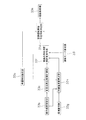
- FIG. 5 shows a control block diagram of activation control.
- the startup control according to the embodiment of the present invention will be described with reference to the control block diagram of FIG.
- the indoor temperature measuring unit 33b starts measuring the suction temperature Tr (see FIG. 6) using the suction temperature sensor, and changes the measured value of the suction temperature Tr every predetermined time. It is transmitted to the inflection point generation time measurement unit 33c and the divergence temperature difference calculation unit 33h.
- the temperature setting unit 33g is provided so that the user can set the blowing temperature of the air conditioner, and transmits the temperature information set by the user to the deviation temperature difference calculation unit 33h.
- the inflection point occurrence time measuring unit 33c starts time measurement from the time ts (see FIG. 6) when the air conditioner 1 is turned on, and the suction temperature Tr is transmitted each time the measured value of the suction temperature Tr is transmitted.
- the 4-point simple moving average value of Tr is calculated, and the 4-point simple moving average value of the suction temperature Tr is written into the memory unit of the microcomputer.
- the inflection point occurrence time measuring unit 33c calculates the slope value of the suction temperature Tr by subtracting the previous four-point simple movement average value from the latest four-point simple movement average value, and the slope value of the suction temperature Tr. Is written in the memory section of the microcomputer.
- the inflection point occurrence time measurement unit 33c determines that an inflection point has occurred when the latest inclination value is 0 or a positive value and the immediately preceding inclination value is a negative value in the cooling mode. Then, the elapsed time value Pi (see FIG. 6) at the judgment time point (inflection point occurrence time) ti (see FIG. 6) is read, and the elapsed time value Pi is transmitted to the inflection point occurrence time remeasurement command unit 33f. In addition, an inflection point generation notification signal is transmitted to the deviation temperature difference calculation unit 33h.
- the inflection point occurrence time measuring unit 33c determines that an inflection point has occurred when the latest inclination value is 0 or a negative value and the immediately preceding inclination value is a positive value in the heating mode. Then, the elapsed time value Pi at the determination time point ti is read, and the measured value of the suction temperature Tr at the determination time point ti together with the elapsed time value Pi is transmitted to the inflection point occurrence time remeasurement command unit 33f and the deviation temperature difference An inflection point occurrence notification signal is transmitted to the calculation unit 33h.
- the divergence temperature difference calculation unit 33h transmits from the set temperature Ts (see FIG. 6) and then transmits from the indoor temperature measurement unit 33b. After calculating the deviation temperature difference value by subtracting the measured value of the suction temperature Tr, the deviation temperature difference value is transmitted to the inflection point occurrence time re-measurement command unit 33f.
- the operation mode setting unit 33i is provided so that the user can set the operation mode of the air conditioner (for example, the cooling operation mode, the heating operation mode, the dehumidifying operation mode, etc.), and is set by the user.
- the obtained operation mode information is transmitted to the inflection point occurrence time remeasurement command unit 33f.
- the inflection point occurrence time re-measurement command unit 33f is configured such that (i) the operation mode information transmitted from the operation mode setting unit 33i is the cooling operation mode information, and the deviation temperature difference value transmitted from the deviation temperature difference calculation unit 33h is When larger than the predetermined value, the elapsed time value Pi transmitted from the inflection point occurrence time measuring unit 33c is transmitted to the air conditioning operation scheduled start time determining unit 33d, and (ii) the operation mode transmitted from the operation mode setting unit 33i.
- a remeasurement command signal is transmitted to the inflection point occurrence time measurement unit 33c, (Iii) When the operation mode information transmitted from the operation mode setting unit 33i is the heating operation mode information and the deviation temperature difference value transmitted from the deviation temperature difference calculation unit 33h is smaller than a predetermined value.
- the elapsed time value Pi transmitted from the inflection point occurrence time measuring unit 33c is transmitted to the air conditioning operation scheduled start time determining unit 33d, and (iv) the operation mode information transmitted from the operation mode setting unit 33i is the heating operation mode information.
- a remeasurement command signal is transmitted to the inflection point occurrence time measurement unit 33c.
- the inflection point occurrence time measuring unit 33c receives the remeasurement command signal, the inflection point occurrence time measuring unit 33c measures the time from when the air conditioner 1 is turned on until the next inflection point occurrence time ti.
- the desired time setting unit 33a is provided so as to be able to set a time at which the user can enjoy the desired air conditioning environment.
- the time information set by the user is sent to the scheduled air conditioning operation start time determination unit 33d.
- the air conditioning operation scheduled start time determination unit 33d determines a time obtained by subtracting the elapsed time value from the desired time set by the desired time setting unit 33a as the next scheduled operation start time.
- the activation control unit 33e starts the operation of the air conditioner when the scheduled operation start time determined by the scheduled air conditioning operation start time determination unit is reached.
- the thermostep signal is generated so that the capacity of the compressor 32 is automatically reduced as the suction temperature Tr approaches the set temperature Ts so that the suction temperature Tr approaches the set temperature Ts. Generated.
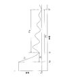
- the time from the power-on time ts to the time ti at which the suction temperature Tr indicates the inflection point (hereinafter referred to as “inflection point occurrence time”) is measured, and from the desired time set by the user. The time at which the inflection point occurrence time is subtracted is determined as the next scheduled operation start time. For this reason, compared with the conventional air conditioner in which the time obtained by subtracting the time Pf (see FIG.
- the air conditioning apparatus 1 can suppress power consumption as compared with a conventional air conditioning apparatus having a precooling / preheating function.
- an inflection point occurrence time remeasurement command unit is provided.
- the inflection point occurrence time Pi can be corrected when the suction temperature Tr at the inflection point occurrence time ti is significantly different from the set temperature Ts. Therefore, in this air conditioning apparatus 1, an air conditioning environment very close to the air conditioning environment desired by the user can be prepared at the desired time set by the user.
- a separate type air conditioner was adopted as the air conditioner 1, but the air conditioner may be a multi-type air conditioner or an integrated floor-type air conditioner. May be.
- the desired time setting unit 33a may be designed so that the desired time is directly input. It may be designed so that the desired time is input to the.
- the time from the power-on time point ts to the time point ti at which the suction temperature Tr indicates the inflection point (hereinafter referred to as “inflection point occurrence time”) is measured and set by the user. The time obtained by subtracting the inflection point occurrence time from the desired time is determined as the next scheduled operation start time, but the time from the power-on time ts to the time when the thermo step signal decreases to a predetermined value (hereinafter referred to as “thermo step decrease”).
- the air conditioner may be designed so that the time obtained by subtracting the thermostep decrease time from the desired time is determined as the next scheduled operation start time.
- the inflection point occurrence time re-measurement instruction unit 33f is such that the operation mode information transmitted from the operation mode setting unit 33i is the cooling operation mode information, and the deviation temperature difference calculation unit 33h.
- a remeasurement command signal is transmitted to the inflection point occurrence time measuring unit 33c, and the operation mode information transmitted from the operation mode setting unit 33i is the heating operation.
- the remeasurement command signal is transmitted to the inflection point occurrence time measurement unit 33c.
- the generation time re-measurement command unit 33f is configured such that the operation mode information transmitted from the operation mode setting unit 33i is the cooling operation mode information and the deviation temperature difference value transmitted from the deviation temperature difference calculation unit 33h is When the value is equal to or less than the predetermined value, a value obtained by adding a deviation temperature difference value (negative value) to the set temperature (hereinafter referred to as “corrected set temperature”) is transmitted to the temperature setting unit 33g and to the inflection point occurrence time measuring unit 33c When the operation mode information transmitted from the operation mode setting unit 33i is heating operation mode information and the deviation temperature difference value transmitted from the deviation temperature difference calculation unit 33h is equal to or greater than a predetermined value.
- a value obtained by adding a deviation temperature difference value (positive value) to the set temperature (corrected set temperature) is transmitted to the temperature setting unit 33g, and a remeasurement command signal is transmitted to the inflection point occurrence time measuring unit 33c. You may make it do.
- the temperature setting unit 33g rewrites the set temperature value that has been valid up to that point with the corrected set temperature value.
- the deviation temperature difference calculation unit 33h when the inflection point occurrence notification signal is transmitted from the inflection point occurrence time measurement unit 33c, from the set temperature Ts at that time. After calculating the deviation temperature difference value by subtracting the measured value of the suction temperature Tr transmitted from the room temperature measurement unit 33b, the deviation temperature difference value was transmitted to the inflection point occurrence time remeasurement command unit 33f.
- the temperature difference calculating unit 33h calculates an absolute difference between the set temperature Ts and the measured value of the suction temperature Tr transmitted from the indoor temperature measuring unit 33b at that time, and then generates the inflection point of the absolute difference. It may be transmitted to the time remeasurement command unit 33f.
- the operation mode information is unnecessary in the inflection point occurrence time remeasurement command unit 33f, and the inflection point occurrence time remeasurement command unit 33f has an absolute difference transmitted from the deviation temperature difference calculation unit 33h that is greater than a predetermined value.
- a remeasurement command signal is transmitted to the inflection point occurrence time measurement unit 33c, and the inflection point occurrence time measurement is performed when the absolute difference transmitted from the deviation temperature difference calculation unit 33h is equal to or less than a predetermined value.
- the elapsed time value Pi transmitted from the unit 33c is transmitted to the scheduled air conditioning operation start time determination unit 33d.
- the operation mode information is required in the inflection point occurrence time remeasurement command unit 33f, and the inflection point occurrence time remeasurement command unit 33f
- the information is cooling operation mode information and the absolute difference transmitted from the deviation temperature difference calculation unit 33h is larger than a predetermined value
- a value obtained by subtracting the absolute difference from the set temperature (hereinafter referred to as “corrected set temperature value”) is the temperature.
- corrected set temperature value a value obtained by subtracting the absolute difference from the set temperature.
- corrected set temperature value a value obtained by adding an absolute difference to the set temperature
- the temperature setting unit 33g uses the corrected set temperature value as the corrected set temperature value. rewrite.
- the start-up control device for an air conditioner has a feature that the power consumption of the air-conditioning device can be suppressed more than that of a conventional start-up control device for an air-conditioning device. Greatly contributes to power generation.
- Air Conditioning Device 33 Start Control Device (Electrical Equipment Box 33) 33a Desired time setting unit 33b Indoor temperature measurement unit 33c Inflection point generation time measurement unit 33d Air conditioning operation scheduled start time determination unit 33e Start control unit 33f Inflection point generation time remeasurement command unit 33h Deviation temperature difference calculation unit Ts Set temperature Tr Room temperature
Landscapes
- Engineering & Computer Science (AREA)
- Mechanical Engineering (AREA)
- General Engineering & Computer Science (AREA)
- Chemical & Material Sciences (AREA)
- Combustion & Propulsion (AREA)
- Physics & Mathematics (AREA)
- Thermal Sciences (AREA)
- Signal Processing (AREA)
- Fuzzy Systems (AREA)
- Mathematical Physics (AREA)
- Air Conditioning Control Device (AREA)
Abstract
Description
本発明の課題は、室内温度が設定温度に近付くにつれて自動的に圧縮機の能力を低下させて室内温度を設定温度に近づける空気調和装置に前倒し運転をさせる場合において電力消費量を抑制することにある。
このため、この空気調和装置の起動制御装置では、比較的、シンプルなロジックにより変曲点を検出することができる。したがって、この空気調和装置の起動制御装置では、比較的迅速に変曲点を検出することができる。
このため、この空気調和装置の起動制御装置では、変曲点発生時の室内温度が設定温度と著しく乖離している場合に、変曲点発生時間を修正することができる。したがって、この空気調和装置の起動制御装置を利用すれば、希望時刻においてユーザの望む空調環境に非常に近い空調環境を整えることができる。
このため、この空気調和装置の起動制御装置では、変曲点発生時の室内温度が設定温度と著しく乖離している場合に、変曲点発生時間を修正することができる。したがって、この空気調和装置の起動制御装置を利用すれば、希望時刻においてユーザの望む空調環境に非常に近い空調環境を整えることができる。
このため、この空気調和装置の起動制御装置では、変曲点発生時の室内温度が設定温度と著しく乖離している場合に、変曲点発生時間を修正することができる。したがって、この空気調和装置の起動制御装置を利用すれば、希望時刻においてユーザの望む空調環境に非常に近い空調環境を整えることができる。
このため、この空気調和装置の起動制御装置では、変曲点発生時の室内温度が設定温度と著しく乖離している場合に、変曲点発生時間を修正することができる。したがって、この空気調和装置の起動制御装置を利用すれば、希望時刻においてユーザの望む空調環境に非常に近い空調環境を整えることができる。
第2発明に係る空気調和装置の起動制御装置では、比較的、シンプルなロジックにより変曲点を検出することができる。したがって、この空気調和装置の起動制御装置では、比較的迅速に変曲点を検出することができる。
第4発明に係る空気調和装置の起動制御装置では、変曲点発生時の室内温度が設定温度と著しく乖離している場合に、変曲点発生時間を修正することができる。したがって、この空気調和装置の起動制御装置を利用すれば、希望時刻においてユーザの望む空調環境に非常に近い空調環境を整えることができる。
第5発明に係る空気調和装置の起動制御装置では、変曲点発生時の室内温度が設定温度と著しく乖離している場合に、変曲点発生時間を修正することができる。したがって、この空気調和装置の起動制御装置を利用すれば、希望時刻においてユーザの望む空調環境に非常に近い空調環境を整えることができる。
第7発明に係る空気調和装置の起動制御装置を、室内温度が設定温度に近付くにつれて自動的に圧縮機の能力を低下させて室内温度を設定温度に近づける空気調和装置に対して適用すれば、従来の「空気調和装置の運転開始時点からサーモオフ時点までの時間(以下「サーモオフ時間」という)だけ運転開始時刻を前倒しして予冷運転または予熱運転を開始する空気調和機の起動制御装置」を適用するよりも前倒し時間(本発明では制御パラメータ低下到達時間に相当し、従来例ではサーモオフ時間に相当する)が短くなる。したがって、室内温度が設定温度に近付くにつれて自動的に圧縮機の能力を低下させて室内温度を設定温度に近づける空気調和装置に対して、本発明に係る空気調和装置の起動制御装置を利用すれば、従前よりも電力消費量を抑制することができる。
以下、室内機2と室外機3とについてそれぞれ詳細に説明する。
<室内機>
室内機2は、図3に示されるように、主に、設置時に天井に埋設される本体201と、設置時に居室側に露出する化粧パネル202とから構成される。
本体ケーシング211は、図3に示されるように、下面が開口した箱体であって、天板211aと、天板211aの周縁部から下方に延びる側板211bとを有している。この本体ケーシング211には、その内部に各種構成部品が収容されている。
遠心送風機23は、本実施の形態において、ターボファンであり、本体ケーシング211の天板211aの中央に設けられたファンモータ22と、ファンモータ22に連結されて回転駆動される羽根車21とを有している。遠心送風機23は、羽根車21の内部に居室内の空気(以下、室内空気という)を吸入し、羽根車21の外周側に吹き出すことができる。
ドレンパン214は、室内熱交換器20の下側に配置されており、室内熱交換器20において室内空気を冷却する際に室内空気中の水分が凝縮されて生じるドレン水を受け止める。
そして、ファンモータ22により羽根車21が回転させられると、室内空気が図3の矢印F1に示されるように室内機2の吸込口224に吸い込まれる。吸い込まれた室内空気は、本体201のベルマウス215を通じて羽根車21に到達した後、羽根車21の外周側に吹き出される(図3の矢印F1a参照)。羽根車21の外周側に吹き出された室内空気は、羽根車21の外周側に配置された室内熱交換器20によって熱交換された後、吹出口222から室内に吹き出される(図3の矢印F2参照)。また、ルーバ221は、ルーバ駆動専用の小型モータ(図示せず)により上下方向に往復運動可能なように設計されている。
室外機3には、主に、圧縮機32と、圧縮機32の吐出側に接続される四路切換弁33と、圧縮機32の吸入側に接続されるアキュムレータ31と、四路切換弁33に接続された室外熱交換器130と、室外熱交換器130に接続された電動膨張弁34とが収容されている。圧縮機32は、インバータ制御式の圧縮機であり、室内機2の電装品ボックス33から送信されるサーモステップ信号に基づいて運転周波数が調整されて容量制御がなされる。電動膨張弁34は、フィルタ35および液閉鎖弁36を介して配管41に接続されており、この配管41を介して室内熱交換器20の一端と接続される。また、四路切換弁33は、ガス閉鎖弁37を介して配管42に接続されており、この配管42を介して室内熱交換器20の他端と接続されている。なお、配管41,42は、図1の冷媒配管4に相当する。また、室外機3には、室外熱交換器130での熱交換後の空気を外部に排出するためのプロペラファン38が設けられている。このプロペラファン38では、プロペラファンロータ40がファンモータ39によって回転駆動される。
図5には、起動制御の制御ブロック図を示した。以下、図5の制御ブロック図に従って本発明の実施の形態に係る起動制御を説明する。
室内温度測定部33bは、空気調和装置1に電源が投入されると、吸込温度センサにより吸込温度Tr(図6参照)の計測を開始し、その吸込温度Trの計測値を所定時間置きに変曲点発生時間計測部33cおよび乖離温度差算出部33hに送信する。
温度設定部33gは、ユーザが空気調和機の吹出温度を設定することができるようにするために設けられており、ユーザにより設定された温度情報を乖離温度差算出部33hに送信する。
変曲点発生時間計測部33cは、空気調和装置1に電源が投入された時点ts(図6参照)から時間計測を開始すると共に、吸込温度Trの計測値が送信されてくる度に吸込温度Trの4点単純移動平均値を算出し、その吸込温度Trの4点単純移動平均値をマイクロコンピュータのメモリ部に書き込んでいく。また、変曲点発生時間計測部33cは、最新の4点単純移動平均値からその直前の4点単純移動平均値を差し引いて吸込温度Trの傾斜値を算出し、その吸込温度Trの傾斜値をマイクロコンピュータのメモリ部に書き込んでいく。そして、変曲点発生時間計測部33cは、冷房モード時において最新の傾斜値が0又は正の値であり且つその直前の傾斜値が負の値である場合に変曲点が発生したと判断し、その判断時点(変曲点発生時点)ti(図6参照)での経過時間値Pi(図6参照)を読み取り、その経過時間値Piを変曲点発生時間再計測命令部33fに送信すると共に乖離温度差算出部33hに変曲点発生通知信号を送信する。また、変曲点発生時間計測部33cは、暖房モード時において最新の傾斜値が0又は負の値であり且つその直前の傾斜値が正の値である場合に変曲点が発生したと判断し、その判断時点tiの経過時間値Piを読み取り、その経過時間値Piと共にその判断時点tiでの吸込温度Trの計測値を変曲点発生時間再計測命令部33fに送信すると共に乖離温度差算出部33hに変曲点発生通知信号を送信する。
運転モード設定部33iは、ユーザが空気調和機の運転モード(例えば、冷房運転モード、暖房運転モード、除湿運転モードなど)を設定することができるようにするために設けられており、ユーザにより設定された運転モード情報を変曲点発生時間再計測命令部33fに送信する。
変曲点発生時間再計測命令部33fは、(i)運転モード設定部33iから送信される運転モード情報が冷房運転モード情報であって乖離温度差算出部33hから送信される乖離温度差値が所定値よりも大きい場合、変曲点発生時間計測部33cから送信された経過時間値Piを空調運転開始予定時刻決定部33dに送信し、(ii)運転モード設定部33iから送信される運転モード情報が冷房運転モード情報であって乖離温度差算出部33hから送信される乖離温度差値が所定値以下である場合、変曲点発生時間計測部33cに対して再計測命令信号を送信し、(iii)運転モード設定部33iから送信される運転モード情報が暖房運転モード情報であって乖離温度差算出部33hから送信される乖離温度差値が所定値よりも小さい場合、変曲点発生時間計測部33cから送信された経過時間値Piを空調運転開始予定時刻決定部33dに送信し、(iv)運転モード設定部33iから送信される運転モード情報が暖房運転モード情報であって乖離温度差算出部33hから送信される乖離温度差値が所定値以上である場合、変曲点発生時間計測部33cに対して再計測命令信号を送信する。なお、変曲点発生時間計測部33cは、再計測命令信号を受信すると、空気調和装置1に電源が投入された時点から次の変曲点発生時点tiまでの時間を計測する。
空調運転開始予定時刻決定部33dは、希望時刻設定部33aにおいて設定された希望時刻から経過時間値を差し引いた時刻を次の運転開始予定時刻として決定する。
起動制御部33eは、空調運転開始予定時刻決定部で決定された運転開始予定時刻になると空気調和装置の運転を開始させる。
<空気調和装置の特徴>
(1)
本実施の形態に係る空気調和装置1では、吸込温度Trが設定温度Tsに近付くにつれて圧縮機32の能力が自動的に低下させられて吸込温度Trが設定温度Tsに近づくようにサーモステップ信号が生成される。そして、この空気調和装置1では、電源投入時点tsから吸込温度Trが変曲点を示す時点tiまでの時間(以下「変曲点発生時間」という)が計測され、ユーザが設定した希望時刻から変曲点発生時間が差し引かれた時刻が次の運転開始予定時刻と決定される。このため、運転開始時点tsからサーモオフ時点tf(図6参照)までの時間Pf(図6参照)を差し引いた時刻を次の運転開始予定時刻としていた従来の空気調和装置に比べると、予冷運転または予熱運転に費やされる時間がPs(図6参照)分だけ短くなる。したがって、本実施の形態に係る空気調和装置1は、予冷・予熱機能を有する従来の空気調和装置に比べて電力消費量を抑制することができる。
本実施の形態に係る空気調和装置1には、変曲点発生時間再計測命令部が設けられている。このため、この空気調和装置1では、変曲点発生時点tiの吸込温度Trが設定温度Tsと著しく乖離している場合に、変曲点発生時間Piを修正することができる。したがって、この空気調和装置1では、ユーザの設定する希望時刻においてユーザの望む空調環境に非常に近い空調環境を整えることができる。
<変形例>
(A)
先の実施の形態では空気調和装置1としてセパレート型の空気調和装置が採用されたが、空気調和装置は、マルチ式空気調和装置であってもよいし、一体型の床置式空気調和装置であってもよい。
先の実施の形態では特に言及しなかったが、希望時刻設定部33aは、直接的に希望時刻が入力されるように設計されてもかまわないし、例えば「何時間後から」というように間接的に希望時刻が入力されるように設計されてもかまわない。
(C)
先の実施の形態に係る空気調和装置1では電源投入時点tsから吸込温度Trが変曲点を示す時点tiまでの時間(以下「変曲点発生時間」という)が計測され、ユーザが設定した希望時刻から変曲点発生時間が差し引かれた時刻が次の運転開始予定時刻と決定されたが、電源投入時点tsからサーモステップ信号が所定値まで低下する時点までの時間(以下「サーモステップ低下時間」という)を計測し、希望時刻からサーモステップ低下時間を差し引いた時刻を次の運転開始予定時刻と決定するように空気調和装置を設計してもかまわない。
先の実施の形態に係る空気調和装置1では変曲点発生時間再計測命令部33fは、運転モード設定部33iから送信される運転モード情報が冷房運転モード情報であって乖離温度差算出部33hから送信される乖離温度差値が所定値以下である場合、変曲点発生時間計測部33cに対して再計測命令信号を送信し、運転モード設定部33iから送信される運転モード情報が暖房運転モード情報であって乖離温度差算出部33hから送信される乖離温度差値が所定値以上である場合、変曲点発生時間計測部33cに対して再計測命令信号を送信したが、変曲点発生時間再計測命令部33fは、例えば、運転モード設定部33iから送信される運転モード情報が冷房運転モード情報であって乖離温度差算出部33hから送信される乖離温度差値が所定値以下である場合、設定温度に乖離温度差値(負の値)を加えた値(以下「補正設定温度」という)を温度設定部33gに送信すると共に変曲点発生時間計測部33cに対して再計測命令信号を送信するようにし、運転モード設定部33iから送信される運転モード情報が暖房運転モード情報であって乖離温度差算出部33hから送信される乖離温度差値が所定値以上である場合、設定温度に乖離温度差値(正の値)を加えた値(補正設定温度)を温度設定部33gに送信すると共に変曲点発生時間計測部33cに対して再計測命令信号を送信するようにしてもよい。なお、かかる場合、温度設定部33gは、変曲点発生時間再計測命令部33fから補正設定温度値が送信されると、それまで有効であった設定温度値をその補正設定温度値で書き換える。
先の実施の形態に係る空気調和装置1では乖離温度差算出部33hは、変曲点発生時間計測部33cから変曲点発生通知信号が送信されてくると、設定温度Tsから、そのときに室内温度測定部33bから送信されてきた吸込温度Trの計測値を差し引いて乖離温度差値を算出した後、その乖離温度差値を変曲点発生時間再計測命令部33fに送信したが、乖離温度差算出部33hは、例えば、設定温度Tsと、そのときに室内温度測定部33bから送信されてきた吸込温度Trの計測値との絶対差を算出した後、その絶対差を変曲点発生時間再計測命令部33fに送信してもかまわない。かかる場合、変曲点発生時間再計測命令部33fにおいて運転モード情報は不要となり、変曲点発生時間再計測命令部33fは、乖離温度差算出部33hから送信される絶対差が所定値よりも大きい場合に、変曲点発生時間計測部33cに対して再計測命令信号を送信し、乖離温度差算出部33hから送信される絶対差が所定値以下である場合に、変曲点発生時間計測部33cから送信された経過時間値Piを空調運転開始予定時刻決定部33dに送信することになる。
33 起動制御装置(電装品ボックス33)
33a 希望時刻設定部
33b 室内温度測定部
33c 変曲点発生時間計測部
33d 空調運転開始予定時刻決定部
33e 起動制御部
33f 変曲点発生時間再計測命令部
33h 乖離温度差算出部
Ts 設定温度
Tr 室内温度
Claims (7)
- 室内温度(Tr)が設定温度(Ts)に近付くにつれて自動的に圧縮機(32)の能力を低下させて室内温度を前記設定温度に近づける空気調和装置(1)の起動制御を行う空気調和装置の起動制御装置であって、
直接的に又は間接的に希望時刻を設定する希望時刻設定部(33a)と、
前記室内温度を測定する室内温度測定部(33b)と、
前記空気調和装置の運転開始時点から、前記室内温度測定部によって測定される室内温度(以下「測定室内温度」という)が変曲点を示す時点までの時間(以下「変曲点発生時間」という)を計測する変曲点発生時間計測部(33c)と、
前記希望時刻設定部によって設定された前記希望時刻よりも前記変曲点発生時間前の時刻を前記空気調和装置の運転開始予定時刻と決定する空調運転開始予定時刻決定部(33d)と、
前記空調運転開始予定時刻決定部で決定された前記運転開始予定時刻になると前記空気調和装置の運転を開始させる起動制御部(33e)と
を備える空気調和装置の起動制御装置(33)。 - 前記変曲点発生時間計測部は、所定時間間隔毎に前記測定室内温度の移動平均値を算出し記憶する移動平均値算出記憶手段と、最新の前記測定室内温度の移動平均値から直前の前記測定室内温度の移動平均値を差し引いて前記測定室内温度の変化の傾きを算出し記憶する傾き算出記憶手段と、最新の前記変化の傾きの正負符号と直前の前記変化の傾きの正負符号とを比較して前記変曲点を検出する変曲点検出手段とを有する
請求項1に記載の空気調和装置の起動制御装置。 - 前記変曲点の発生時に、前記設定温度と前記測定室内温度との絶対差を算出する絶対差算出部と、
前記絶対差が所定値以上であった場合に、前記変曲点発生時間計測部に対して前記変曲点発生時間を再計測させる変曲点発生時間再計測命令部と
をさらに備える請求項1又は2に記載の空気調和装置の起動制御装置。 - 前記変曲点の発生時に、前記設定温度と前記測定室内温度との絶対差を算出する絶対差算出部と、
前記絶対差が所定値以上であった場合に、前記絶対差を前記設定温度に加えた又は前記設定温度から前記絶対差を差し引いた後に、前記変曲点発生時間計測部に対して前記変曲点発生時間を再計測させる変曲点発生時間再計測命令部と
をさらに備える請求項1又は2に記載の空気調和装置の起動制御装置。 - 前記変曲点の発生時に、前記設定温度から前記測定室内温度を差し引いて乖離温度差を算出する乖離温度差算出部(33h)と、
前記乖離温度差が所定値以上又は所定値以下であった場合に、前記変曲点発生時間計測部に対して前記変曲点発生時間を再計測させる変曲点発生時間再計測命令部(33f)と
をさらに備える請求項1又は2に記載の空気調和装置の起動制御装置。 - 前記変曲点の発生時に、前記設定温度から前記測定室内温度を差し引いて乖離温度差を算出する乖離温度差算出部と、
前記乖離温度差が所定値以上又は所定値以下であった場合に、前記乖離温度差を前記設定温度に加えた後に、前記変曲点発生時間計測部に対して前記変曲点発生時間を再計測させる前記変曲点発生時間再計測命令部と
をさらに備える請求項1又は2に記載の空気調和装置の起動制御装置。 - 室内温度が設定温度に近付くにつれて自動的に圧縮機の能力を低下させて室内温度を前記設定温度に近づける空気調和装置の起動制御を行う空気調和装置の起動制御装置であって、
直接的に又は間接的に希望時刻を設定する希望時刻設定部と、
前記室内温度を測定する室内温度測定部と、
空気調和装置の運転開始時点から、前記圧縮機に送信される制御パラメータ値が所定値まで低下する時点までの時間(以下「制御パラメータ低下到達時間」という)を計測する制御パラメータ低下到達時間時間計測部と、
前記希望時刻設定部によって設定された前記希望時刻よりも前記制御パラメータ低下到達時間前の時刻を前記空気調和装置の運転開始予定時刻と決定する空調運転開始予定時刻設定部と、
前記空調運転開始時刻設定部で設定された前記運転開始予定時刻になると前記空気調和装置の運転を開始させる起動制御部と
を備える空気調和装置の起動制御装置。
Priority Applications (4)
| Application Number | Priority Date | Filing Date | Title |
|---|---|---|---|
| AU2009269483A AU2009269483B8 (en) | 2008-07-11 | 2009-07-08 | Startup control apparatus of air conditioner |
| CN2009801270240A CN102089593B (zh) | 2008-07-11 | 2009-07-08 | 空调装置的起动控制装置 |
| US13/002,201 US9400120B2 (en) | 2008-07-11 | 2009-07-08 | Startup control apparatus of air conditioner |
| EP09794188.4A EP2320152B1 (en) | 2008-07-11 | 2009-07-08 | Air conditioner start control device |
Applications Claiming Priority (2)
| Application Number | Priority Date | Filing Date | Title |
|---|---|---|---|
| JP2008-181957 | 2008-07-11 | ||
| JP2008181957A JP4569678B2 (ja) | 2008-07-11 | 2008-07-11 | 空気調和装置の起動制御装置 |
Publications (1)
| Publication Number | Publication Date |
|---|---|
| WO2010004740A1 true WO2010004740A1 (ja) | 2010-01-14 |
Family
ID=41506867
Family Applications (1)
| Application Number | Title | Priority Date | Filing Date |
|---|---|---|---|
| PCT/JP2009/003175 Ceased WO2010004740A1 (ja) | 2008-07-11 | 2009-07-08 | 空気調和装置の起動制御装置 |
Country Status (7)
| Country | Link |
|---|---|
| US (1) | US9400120B2 (ja) |
| EP (1) | EP2320152B1 (ja) |
| JP (1) | JP4569678B2 (ja) |
| KR (1) | KR20110030621A (ja) |
| CN (1) | CN102089593B (ja) |
| AU (1) | AU2009269483B8 (ja) |
| WO (1) | WO2010004740A1 (ja) |
Cited By (1)
| Publication number | Priority date | Publication date | Assignee | Title |
|---|---|---|---|---|
| CN102141289A (zh) * | 2011-02-15 | 2011-08-03 | 深圳达实智能股份有限公司 | 一种中央空调系统最佳开机时间诊断与分析的方法及装置 |
Families Citing this family (11)
| Publication number | Priority date | Publication date | Assignee | Title |
|---|---|---|---|---|
| WO2013019537A2 (en) * | 2011-07-29 | 2013-02-07 | Carrier Corporation | Hvac systems |
| JP6025833B2 (ja) * | 2012-05-14 | 2016-11-16 | 三菱電機株式会社 | 空調装置および空気調和システム |
| JP5896852B2 (ja) * | 2012-07-20 | 2016-03-30 | アズビル株式会社 | 空調システムの最適起動停止制御装置および最適起動停止制御方法 |
| CN105190193B (zh) * | 2013-03-29 | 2018-06-29 | 三菱电机株式会社 | 空调控制装置、空调控制系统和空调控制方法 |
| CN103322649B (zh) * | 2013-06-20 | 2016-01-13 | 四川长虹电器股份有限公司 | 一种控制方法及装置 |
| CN103335377B (zh) * | 2013-07-01 | 2016-05-25 | 青岛海信日立空调系统有限公司 | 空调控制装置及其定时开机的控制方法 |
| KR102431708B1 (ko) * | 2016-03-04 | 2022-08-11 | 삼성전자주식회사 | 공기 조화를 위한 제어 장치 및 그 제어 방법 |
| EP3816527B1 (en) * | 2018-06-26 | 2024-02-28 | Mitsubishi Electric Corporation | Air conditioning management device and air conditioning system |
| CN108870633B (zh) * | 2018-06-28 | 2019-10-25 | 珠海格力电器股份有限公司 | 空调系统的控制方法和装置 |
| CN109855244B (zh) * | 2019-02-18 | 2020-04-28 | 珠海格力电器股份有限公司 | 一种节约能源的定时控制方法及系统 |
| CN110925223A (zh) * | 2019-11-14 | 2020-03-27 | 江苏大学镇江流体工程装备技术研究院 | 一种轴流泵外特性曲线表征方法 |
Citations (3)
| Publication number | Priority date | Publication date | Assignee | Title |
|---|---|---|---|---|
| JPS62272046A (ja) | 1986-05-21 | 1987-11-26 | Daikin Ind Ltd | 空気調和機の起動制御装置 |
| JPH02133747A (ja) * | 1988-11-15 | 1990-05-22 | Toshiba Corp | 空気調和装置 |
| JP2002310481A (ja) * | 2001-04-10 | 2002-10-23 | Sharp Corp | 空気調和機 |
Family Cites Families (15)
| Publication number | Priority date | Publication date | Assignee | Title |
|---|---|---|---|---|
| US4172555A (en) * | 1978-05-22 | 1979-10-30 | Levine Michael R | Adaptive electronic thermostat |
| JPS5572746A (en) * | 1978-11-21 | 1980-05-31 | Matsushita Electric Ind Co Ltd | Controlling device for household air conditioner |
| JPS6099945A (ja) * | 1983-11-04 | 1985-06-03 | Toshiba Corp | 空気調和機 |
| US4909041A (en) * | 1984-07-27 | 1990-03-20 | Uhr Corporation | Residential heating, cooling and energy management system |
| US4674027A (en) * | 1985-06-19 | 1987-06-16 | Honeywell Inc. | Thermostat means adaptively controlling the amount of overshoot or undershoot of space temperature |
| JPH04257674A (ja) * | 1991-02-06 | 1992-09-11 | Sanyo Electric Co Ltd | 冷凍機の制御装置 |
| JPH04270854A (ja) * | 1991-02-26 | 1992-09-28 | Hitachi Ltd | 空気調和機の制御方法 |
| US5152152A (en) * | 1992-02-10 | 1992-10-06 | Thermo King Corporation | Method of determining refrigerant charge |
| US5592058A (en) * | 1992-05-27 | 1997-01-07 | General Electric Company | Control system and methods for a multiparameter electronically commutated motor |
| KR0180596B1 (ko) * | 1995-05-10 | 1999-05-01 | 정몽원 | 냉동저장고의 온도 보상방법 |
| KR100379496B1 (ko) | 2000-07-05 | 2003-04-10 | 엘지전자 주식회사 | 멀티 공기 조화기의 운전 제어 장치 및 방법 |
| US6520746B2 (en) * | 2000-09-27 | 2003-02-18 | Lg Electronics Inc. | Apparatus and method for controlling operation of reciprocating compressor |
| US7992630B2 (en) * | 2001-03-12 | 2011-08-09 | Davis Energy Group, Inc. | System and method for pre-cooling of buildings |
| KR100396849B1 (ko) * | 2001-03-26 | 2003-09-03 | 엘지전자 주식회사 | 멀티 컴프레서가 적용된 공기 조화기의 제어 방법 |
| KR100766177B1 (ko) * | 2006-08-04 | 2007-10-10 | 주식회사 대우일렉트로닉스 | 공기 조화기의 운전 제어 방법 |
-
2008
- 2008-07-11 JP JP2008181957A patent/JP4569678B2/ja not_active Expired - Fee Related
-
2009
- 2009-07-08 CN CN2009801270240A patent/CN102089593B/zh not_active Expired - Fee Related
- 2009-07-08 KR KR1020117001390A patent/KR20110030621A/ko not_active Ceased
- 2009-07-08 EP EP09794188.4A patent/EP2320152B1/en not_active Not-in-force
- 2009-07-08 WO PCT/JP2009/003175 patent/WO2010004740A1/ja not_active Ceased
- 2009-07-08 AU AU2009269483A patent/AU2009269483B8/en not_active Ceased
- 2009-07-08 US US13/002,201 patent/US9400120B2/en not_active Expired - Fee Related
Patent Citations (3)
| Publication number | Priority date | Publication date | Assignee | Title |
|---|---|---|---|---|
| JPS62272046A (ja) | 1986-05-21 | 1987-11-26 | Daikin Ind Ltd | 空気調和機の起動制御装置 |
| JPH02133747A (ja) * | 1988-11-15 | 1990-05-22 | Toshiba Corp | 空気調和装置 |
| JP2002310481A (ja) * | 2001-04-10 | 2002-10-23 | Sharp Corp | 空気調和機 |
Non-Patent Citations (1)
| Title |
|---|
| See also references of EP2320152A4 |
Cited By (1)
| Publication number | Priority date | Publication date | Assignee | Title |
|---|---|---|---|---|
| CN102141289A (zh) * | 2011-02-15 | 2011-08-03 | 深圳达实智能股份有限公司 | 一种中央空调系统最佳开机时间诊断与分析的方法及装置 |
Also Published As
| Publication number | Publication date |
|---|---|
| EP2320152A4 (en) | 2015-03-04 |
| EP2320152A1 (en) | 2011-05-11 |
| JP4569678B2 (ja) | 2010-10-27 |
| US9400120B2 (en) | 2016-07-26 |
| CN102089593A (zh) | 2011-06-08 |
| AU2009269483B2 (en) | 2012-11-01 |
| KR20110030621A (ko) | 2011-03-23 |
| AU2009269483B8 (en) | 2013-01-10 |
| US20110107781A1 (en) | 2011-05-12 |
| JP2010019515A (ja) | 2010-01-28 |
| EP2320152B1 (en) | 2017-10-11 |
| CN102089593B (zh) | 2013-03-27 |
| AU2009269483A1 (en) | 2010-01-14 |
Similar Documents
| Publication | Publication Date | Title |
|---|---|---|
| JP4569678B2 (ja) | 空気調和装置の起動制御装置 | |
| JP5281373B2 (ja) | 空気調和機およびその制御方法 | |
| CN111630326B (zh) | 空调装置 | |
| KR20100059522A (ko) | 공기조화기의 제어방법 | |
| JP5871747B2 (ja) | 空気調和機 | |
| JP7212283B2 (ja) | 空気調和装置 | |
| CN102869926A (zh) | 外气处理空调机及使用其的多级空调系统 | |
| AU2021230666B2 (en) | Air-conditioning apparatus | |
| JP2011137597A (ja) | 空気調和装置 | |
| CN111587348B (zh) | 空调装置 | |
| JP4478082B2 (ja) | 空気調和機の制御方法 | |
| CN113834248A (zh) | 空调机 | |
| JP6760314B2 (ja) | 空気調和装置 | |
| JP2019138521A (ja) | 空気調和装置 | |
| JP6562139B2 (ja) | 冷凍装置 | |
| WO2020070890A1 (ja) | 空気調和機 | |
| JP2022177478A (ja) | 空気調和機 | |
| CN109186043A (zh) | 壁挂式空调及其控制方法 | |
| KR100775616B1 (ko) | 공기청정 운전모드를 갖는 에어컨의 운전 제어방법 | |
| WO2021181486A1 (ja) | 空調システム、空調制御装置、空調方法及びプログラム | |
| JP2006084044A (ja) | 空気調和機 | |
| JP2024165966A (ja) | 制御装置および空気調和装置 |
Legal Events
| Date | Code | Title | Description |
|---|---|---|---|
| WWE | Wipo information: entry into national phase |
Ref document number: 200980127024.0 Country of ref document: CN |
|
| 121 | Ep: the epo has been informed by wipo that ep was designated in this application |
Ref document number: 09794188 Country of ref document: EP Kind code of ref document: A1 |
|
| WWE | Wipo information: entry into national phase |
Ref document number: 13002201 Country of ref document: US |
|
| NENP | Non-entry into the national phase |
Ref country code: DE |
|
| ENP | Entry into the national phase |
Ref document number: 20117001390 Country of ref document: KR Kind code of ref document: A |
|
| REEP | Request for entry into the european phase |
Ref document number: 2009794188 Country of ref document: EP |
|
| WWE | Wipo information: entry into national phase |
Ref document number: 2009794188 Country of ref document: EP |
|
| WWE | Wipo information: entry into national phase |
Ref document number: 2009269483 Country of ref document: AU |
|
| ENP | Entry into the national phase |
Ref document number: 2009269483 Country of ref document: AU Date of ref document: 20090708 Kind code of ref document: A |