WO2010007745A1 - 撮像装置 - Google Patents
撮像装置 Download PDFInfo
- Publication number
- WO2010007745A1 WO2010007745A1 PCT/JP2009/003197 JP2009003197W WO2010007745A1 WO 2010007745 A1 WO2010007745 A1 WO 2010007745A1 JP 2009003197 W JP2009003197 W JP 2009003197W WO 2010007745 A1 WO2010007745 A1 WO 2010007745A1
- Authority
- WO
- WIPO (PCT)
- Prior art keywords
- holding member
- screw
- hole
- ccd
- adjustment hole
- Prior art date
- Legal status (The legal status is an assumption and is not a legal conclusion. Google has not performed a legal analysis and makes no representation as to the accuracy of the status listed.)
- Ceased
Links
Images




Classifications
-
- G—PHYSICS
- G03—PHOTOGRAPHY; CINEMATOGRAPHY; ANALOGOUS TECHNIQUES USING WAVES OTHER THAN OPTICAL WAVES; ELECTROGRAPHY; HOLOGRAPHY
- G03B—APPARATUS OR ARRANGEMENTS FOR TAKING PHOTOGRAPHS OR FOR PROJECTING OR VIEWING THEM; APPARATUS OR ARRANGEMENTS EMPLOYING ANALOGOUS TECHNIQUES USING WAVES OTHER THAN OPTICAL WAVES; ACCESSORIES THEREFOR
- G03B17/00—Details of cameras or camera bodies; Accessories therefor
- G03B17/02—Bodies
-
- H—ELECTRICITY
- H04—ELECTRIC COMMUNICATION TECHNIQUE
- H04N—PICTORIAL COMMUNICATION, e.g. TELEVISION
- H04N23/00—Cameras or camera modules comprising electronic image sensors; Control thereof
- H04N23/50—Constructional details
- H04N23/54—Mounting of pick-up tubes, electronic image sensors, deviation or focusing coils
Definitions
- the present invention relates to an imaging apparatus having an imaging element. More specifically, the present invention relates to a technique for assembling an optical system in an imaging apparatus including an imaging element.
- various optical elements such as a lens and an imaging element (for example, a CCD) are arranged.
- an imaging element for example, a CCD
- various improvements have been made on the shape and arrangement of the members supporting each optical element, in addition to the improvement of the performance of each optical element itself.
- Patent Document 1 when an optical system is assembled, a packing is provided between an image sensor and an optical element adjacent to the image sensor to prevent dust from entering the image sensor.
- Various shapes of the packing have been studied, and Patent Document 1 discloses the configuration shown in FIG. 5 and the configuration shown in FIG.
- Patent Document 1 points out the occurrence of a gap due to deformation in the assembly process. Further, the structure of the packing described in FIG. 1 of Patent Document 1 is complicated and expensive.
- Patent Document 2 the technique for adjusting the mounting angle of the CCD using three adjusting screws described in Patent Document 2 is intuitively how the mounting angle of the CCD changes according to the screwing amount of each adjusting screw. It was difficult to understand, trial and error was required, and it was difficult to accurately adjust the mounting angle of the CCD.
- An object of the present invention is to provide a technique applicable in an assembly process of an optical system that is useful for forming an accurate subject image on an image sensor.
- a specific first object of the present invention is to provide a member that reliably prevents dust from entering between optical members such as an image sensor with a simple configuration.
- a second object of the present invention is to provide a structure for making it possible to adjust the angle with respect to the optical axis of the image pickup element with high accuracy independently with respect to two orthogonal directions, with a simple configuration. .
- An imaging device includes an imaging device, a plate-like body to which the imaging device is attached, and a holding member that holds the plate-like body, and the plate-like body has at least one fixing hole. And a second portion having at least one adjustment hole formed therein, and penetrating through the at least one fixing hole and the at least one adjustment hole, respectively.
- the plate-like body and the holding member are stacked in a direction substantially parallel to a direction in which an optical axis extends, and the holding is performed so that the imaging element attached to the second portion and the optical axis are perpendicular to each other.
- the angle of the second part with respect to the member may be adjusted.
- the imaging apparatus further includes at least one bridge portion that connects the first portion and the second portion, the at least one bridge portion is elastically deformable, and the first portion is fixed to the holding member.
- the positional relationship between the second portion and the holding member may be adjusted by elastic deformation of the at least one bridge portion.
- the at least one bridge portion may extend in a direction substantially parallel to a straight line connecting the at least one fixing hole and the at least one adjustment hole.
- the at least one fixing hole is a single fixing hole
- the at least one adjusting hole includes a first adjusting hole and a second adjusting hole
- the at least one bridge portion includes the fixing hole and the first adjusting hole.
- a first bridge portion that is substantially parallel to a straight line that connects the holes
- a second bridge portion that is substantially parallel to a straight line that connects the fixing holes and the second adjustment holes, and is substantially perpendicular to the first bridge portion.
- a second bridge portion extending in the direction.
- the plate-like body is elastically deformable, and when the first portion is fixed to the holding member, the positional relationship between the second portion and the holding member is caused by elastic deformation of the plate-like body. It may be adjusted.
- Each of the plurality of fixing members is a screw
- the first adjustment hole is a long hole having a long diameter longer than a diameter of the screw and parallel to the first bridge portion, and the second adjustment hole.
- the adjustment hole may be a round hole having a diameter larger than the diameter of the screw.
- the imaging apparatus further includes at least one elastic body between the second part of the plate-like body and the holding member, and the second part is attached to the holding member by a screw as the fixing member.
- a force is applied in the approaching direction, and a force is applied to the second portion in a direction away from the holding member by the at least one elastic body, thereby adjusting the position of the second portion and the holding member after adjustment. A relationship may be maintained.
- the action point of the at least one elastic body may be set so that the force by the screw and the force by the at least one elastic body act on substantially the same position of the second portion.
- the at least one bridge portion is warped in a direction away from the holding member, and a force is applied to the second portion in a direction approaching the holding member by a screw as the fixing member, Due to the warp applied to the at least one bridge portion, a force is applied to the second portion in a direction away from the holding member, thereby maintaining the positional relationship between the adjusted second portion and the holding member. May be.
- the plate-like body is held by the holding member using the plurality of fixing members that respectively penetrate the first portion fixing hole and the second portion adjusting hole of the plate-like body such as a sheet metal. It is comprised so that. Since the first part and the second part are not integrated, the first part is fixed using the fixing hole, and the positional relationship between the second part and the holding member (for example, the inclination of the second part with respect to the optical axis) ) Can be adjusted. In particular, since the first portion is fixed to the holding member, it is possible to stably adjust the inclination of the second portion.
- an elastic member is disposed so as to surround a space between the plurality of optical members, and at least one optical member comes into contact with the elastic member on the inclined surface of the elastic member inclined with respect to the optical axis. Since the optical member and the elastic member are not brought into contact with each other at the uppermost end portion of the inclined surface, the above-described space can be reliably sealed with a simple configuration, thereby preventing dust from entering.
- FIG. 1 is a cross-sectional view of a lens barrel 1 by a plane including an optical axis 3.
- FIG. 2 is a detailed sectional view of a CCD unit 2.
- FIG. The assembly drawing of the CCD unit 2 is shown. It is an enlarged view of the sheet metal. It is sectional drawing of the sheet metal 42 of the clamp
- FIG. 6 is a perspective view of a cushion 45. It is sectional drawing of the cushion 45 cut
- FIG. It is a figure which shows the state just before CCD44 is assembled
- FIG. It is a figure which shows the state immediately after CCD44 was assembled
- FIG. It is a figure which shows the cushion 45 formed using three metal mold
- the imaging device is a digital camera.
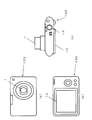
- FIG. 1A to 1C show the appearance of the digital camera 100 according to the present embodiment.
- (A) is a front view
- (b) is a rear view
- (c) is a top view.
- the digital camera 100 has a lens barrel 1.
- the image sensor outputs an electrical signal having a magnitude corresponding to the intensity of the received light. Thereafter, the electrical signal is digitized to generate video data.
- An image based on the video data is displayed on the liquid crystal display 10 shown in FIG.
- the shutter button 12 shown in FIG. 1C is pressed, the image data at that time is written to a memory card (not shown).
- the CCD is adjusted to be perpendicular to the optical axis of the optical system of the digital camera 100. Since the image formation state on the CCD is uniform, no blurring of the image occurs.
- a cushion (a rubber cushion in this embodiment), which is an elastic member, is disposed between the CCD and the optical filter disposed adjacent to the CCD, and seals the space between the CCD and the optical filter. It has stopped.
- the cushion has a structure that is easy to manufacture, and can very easily and reliably seal the space between the CCD and the optical filter.
- the “optical system” includes a lens, a prism, an optical filter, and a CCD.
- the elements and components that make up the optical system are called optical elements.
- FIG. 2 is a sectional view of the lens barrel 1 by a plane including the optical axis 3. Light from the subject enters the lens barrel 1 from the upper side in FIG. FIG. 2 also shows a CCD unit 2 disposed behind the digital camera 100 rather than the lens barrel 1.
- FIG. 3 is a detailed sectional view of the CCD unit 2.
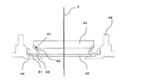
- a CCD 44, a cushion 45, and an optical filter 46 are disposed perpendicular to the optical axis 3.
- the light from the subject enters the CCD unit 2 from the lens barrel 1 along the direction indicated by the optical axis 3 in the drawing.
- the incident light from the subject first passes through the optical filter 46.
- the optical filter 46 is, for example, an infrared cut filter or an ultraviolet cut filter. Thereafter, the light passes through the space 30 existing between the optical filter 46 and the CCD 44 and enters the CCD 44.
- the CCD 44 outputs an electrical signal corresponding to the incident light.
- the electric signal is output via a flexible printed circuit board (described later) connected to the CCD 44.
- the cushion 45 and the optical filter 46 are pasted with an adhesive.
- the CCD 44 and the cushion 45 are in contact with each other with no gap. More specifically, the latter is pressed against the cushion 45, and the cushion 45 is elastically deformed. This means that the force pressed from the CCD 44 is balanced with the restoring force of the cushion 45 at the contact position between the two. Further, the CCD 44 is pressed against the cushion 45 in the middle of the inclined surface of the cushion 45 inclined with respect to the optical axis. In this state, there is no gap between the CCD 44 and the cushion 45. The space 30 is completely sealed by the CCD 44, the cushion 45, and the optical filter 46, and dust from the outside does not enter the space 30.
- FIG. 4 shows an assembly drawing of the CCD unit 2.
- the CCD unit 2 includes a sheet metal 42, a flexible printed circuit board 43, a CCD 44, a cushion 45, an optical filter 46, springs 47b and 47c, and a master flange 48, which are stacked and assembled in this order. It is done. The components from the sheet metal 42 to the springs 47b and 47c are fixed and held on the master flange 48 using three screws 41a to 41c.
- the master flange 48 functions as a holding member that holds many parts described above.
- the sheet metal 42 is a metal plate-like body to which the flexible printed circuit board 43 and the CCD 44 are attached. Details of the sheet metal 42 will be described later with reference to FIG.
- the flexible printed circuit board 43 is electrically connected to the CCD 44 and has wiring and a circuit for transmitting an electric signal output from the CCD 44 to the inside of the digital camera 100.
- the springs 47b and 47c are, for example, coil springs, through which the screws 41b and 41c penetrate.
- the springs 47b and 47c exert an elastic force in a direction opposite to the direction in which the screws 41b and 41c are tightened (the direction toward the master flange 48), thereby causing the sheet metal 42 sandwiched between them to the optical filter 46. Prevents rattling of the elements.
- FIG. 5 is an enlarged view of the sheet metal 42. Screws 41a to 41c shown in FIG. 4 are tightened in the direction from the front side to the back side of FIG.
- the sheet metal 42 according to this embodiment is roughly composed of four parts. Specifically, the sheet metal 42 includes a first portion 50a, a second portion 50b, and two bridge portions 50c and 50d.
- a fixing screw hole 42a is formed in the first portion 50a.
- the fixing screw hole 42a is a hole through which the screw 41a passes.
- the adjustment screw holes 42b and 42c are opened in the second portion 50b.
- the adjusting screw holes 42b and 42c are holes through which the screws 41b and 41c pass, respectively.
- the second portion 50 b includes a step portion 51 for attaching the CCD 44 and the flexible printed circuit board 43.
- the bridge portions 50c and 50d connect the first portion 50a and the second portion 50b and have a relatively narrow width.
- the sheet metal 42 to which the CCD 44 is attached has a structure that can be adjusted so that the CCD 44 is perpendicular to the optical axis after the CCD unit 2 is assembled.
- One of the main structures provided for this purpose is the bridge portions 50c and 50d.
- the structure and the adjusting method will be described in detail.
- This process may be performed during the assembly of the CCD unit 2 or may be performed after the assembly process is completed.
- the bridge portion 50c is provided so as to extend in a direction (X-axis direction in FIG. 5) substantially parallel to a straight line connecting the fixing screw hole 42a and the adjusting screw hole 42b.
- the bridge portion 50d is provided so as to extend in a direction (Y-axis direction in FIG. 5) substantially parallel to a straight line connecting the fixing screw hole 42a and the adjustment screw hole 42c.
- the screws 41a and 41c are provided with a stepped portion q2 below the flange portion (screw head portion) q1.
- the fixing screw hole 42a is a round hole, and its diameter is set so as to substantially match the diameter of the stepped portion q2 of the screw 41a.
- the screw hole 42c is a long hole, and its long side P is set longer than the diameter of the stepped portion q2 of the screw 41c, and its short side Q is set so as to substantially match the diameter of the screw 42a. Yes.
- the sheet metal 42 is connected to the master flange by the screw 41a and the screw 41c. 48 is accurately positioned.
- the screw 41a is completely tightened into the fixing screw hole 42a. Subsequently, the screw 41b is fastened to the screw hole 42b.
- the diameter R of the screw hole 42b is larger than the diameter of the screw 41b. The reason is to provide a margin in view of the fact that the position of a screw hole (not shown) provided in the master flange 48 may be slightly shifted due to a manufacturing error.
- the screw holes 42a and 42c have already been fastened with the screws 41a and 41c, but the screw 41b can be reliably inserted into the screw hole 42b by making the diameter R of the screw hole 42b larger than the diameter of the screw 41b.
- the screw hole 42b is also referred to as a “fool hole”.
- the screws 41b and 41c are not completely tightened into the screw holes 42b and 42c. This is because the angle of the second portion 50b with respect to the master flange 48 is adjusted according to the respective tightening heights.
- the X-axis direction and the Y-axis direction in FIG. 5 are parallel to the respective sides of the rectangular CCD 44.
- the bridge portion 50d is elastically deformed, and the magnitude of the deformation is determined according to the height at which the screw 41c is fastened to the screw hole 42c. If the screw 41c is deeply tightened, the bridge portion 50d is greatly deformed in the direction from the front to the back of the paper, and if it is shallowly tightened, the degree of deformation is small.
- the angle of the second portion 50b with respect to the master flange 48 changes in proportion to the tightening height of the screw 41c due to the elastic deformation of the bridge portion 50d with respect to the direction along the Y axis. Thus, only the angle in the Y-axis direction of the CCD 44 attached to the second portion 50b can be adjusted without changing the angle in the X-axis direction.
- the bridge portion 50c is elastically deformed, and the magnitude of the deformation is determined according to the height at which the screw 41b is fastened to the screw hole 42b. If the screw 41b is tightened deeply, the bridge portion 50c is greatly deformed in the direction from the front to the back of the paper, and if it is tightened shallowly, the degree of deformation is small.
- the angle of the second portion 50b with respect to the master flange 48 changes in proportion to the tightening height of the screw 41b due to elastic deformation of the bridge portion 50c in the direction along the X axis. Thus, only the angle in the X-axis direction of the CCD 44 attached to the second portion 50b can be adjusted independently without changing the angle in the Y-axis direction.
- the bridge portions 50c and 50d are designed to be elastically deformed according to the tightening height of the screws 41b and 41c. Therefore, it is preferable that the bridge portions 50c and 50d have a configuration that easily causes elastic deformation. For example, when the widths of the bridge portions 50c and 50d are made narrower and longer, the spring coefficients (elastic coefficients) of the bridge portions 50c and 50d can be reduced. Alternatively, the spring coefficient can be adjusted by the material of the bridge portions 50c and 50d.
- the second portion 50b does not elastically deform regardless of the tightening degree of the screws 41b and 41c. This is because if the second portion 50b to which the CCD 44 is attached is deformed, the positional relationship between the angle of the CCD 44 and the optical axis varies due to factors other than the height adjustment by tightening the screws 41b and 41c.
- the angle of the second portion 50b with respect to the master flange 48 can be adjusted in the direction from the front side to the back side in FIG.
- the springs 47 b and 47 c shown in FIG. 4 are provided in this embodiment in order to ensure that the peripheral portions of the sheet metal 42 screw holes 42 b and 42 c are brought into contact with the flanges of the screws 41 b and 41 c. Provided.
- FIG. 6 is a cross-sectional view of the sheet metal 42 at the tightening portion when the screws 41b and 41c are tightened.
- the springs 47b and 47c give an elastic force in the direction opposite to the tightening direction of the screws 41b and 41c. This makes it possible to change the angle of the second portion 50b in the direction from the back of the page of FIG. 5 to the front, and when adjusting the height of the screws 41b and 41c, the bridge portions 50c and 50d are changed beyond the elastic range. Even at this time, the flanges of the screws 41b and 41c can be reliably brought into contact with the peripheral portions of the sheet metal 42 screw holes 42b and 42c by the springs 47b and 47c.
- the axes of the springs 47b and 47c are aligned with the axes of the screws 41b and 41c.
- the action point S1 when the screws 41b and 41c clamp the sheet metal 42 and the action point S2 where the springs 47b and 47c act on the sheet metal 42 are brought close to each other.
- the operating point of the screw and the operating point of the spring are substantially the same positions in the vicinity of the screw holes 42b and 42c. If the operating point of the screw is separated from the operating point of the spring, the second portion 50b is easily deformed. Therefore, in order to reduce unnecessary load on the second portion 50b, the operating point of the screw and the operating point of the spring are set at substantially the same position.
- any one of 41b and 41c may be tightened or loosened. Trial and error becomes unnecessary, and the work time for adjustment can be greatly shortened.
- the master flange 48 is designed to be orthogonal to the optical axis and is attached to the digital camera 100 main body.
- the angle of the second portion 50b to which the CCD 44 is attached can be adjusted independently by screws with respect to the direction along the X axis or the Y axis by the mechanism of the present application. On the other hand, it can be adjusted accurately so as to be vertical.
- the tilt adjustment can be performed independently and stably in both directions of the X axis and the Y axis only by completely tightening only the screw 41a.
- the construction of the sheet metal is also very simple.
- the screw 41a Since the screw 41a is completely tightened, even if an external force such as vibration or drop is applied, the inclination of the second portion 50b hardly changes.
- the inclination of the second portion 50b can be maintained more stably.
- the position of the bridge portion and the spring can be adjusted while applying forces in opposite directions, a fine angle adjustment is possible, and the accuracy of the position can be increased.
- the sheet metal 42 is positioned in the plane direction (XY plane direction) by the outer diameter of the stepped portion q2 provided below the flange portion (screw head portion) q1. Even when the inclination of the CCD is adjusted by the screws 41b and 41c, the sheet metal 42 is always positioned in the plane direction (XY plane direction) by the outer diameter of the stepped portion q2 of the screws 41a and 41c.
- the screws 41a, 41b, and 41c are usually made of a material such as metal or ceramic with high hardness. Therefore, even when the CCD is tilted or when an external force such as vibration or drop is applied, even if the end surface of the screw hole 42c provided in the sheet metal 42 and the stepped portion q2 of the screw 41c are rubbed, the resin and metal As in the case of rubbing, there is no occurrence of shaving or squeaking (stick-slip), and a change in tilt is unlikely to occur. In addition, there is an advantage that there is little change in inclination due to environmental changes and changes with time.
- the advantage of this invention will be emphasized more. That is, since the master flange is generally composed of a resin part, the protrusion of the resin part and the hole of the sheet metal are engaged. Then, at the time of tilt adjustment, the resin projection is scraped, or the resin projection and the end face of the hole portion of the sheet metal do not slide smoothly, so that it is impossible to adjust the tilt with high accuracy. Therefore, the advantage by the structure of this invention is very useful.
- FIG. 7 is a perspective view of the cushion 45. As is clear from FIG. 7, the cushion 45 is configured such that one opening is larger than the other opening.
- FIG. 8 is a cross-sectional view of the cushion 45 cut along the assembly direction.
- the cushion 45 has an inclined surface 80 that is inclined with respect to the optical axis 3. Due to the presence of the inclined surface 80, the opening 82 is configured to be larger than the other opening 83.
- the frame 81 that forms the periphery of the opening 83 of the cushion 45 is perpendicular to the optical axis 3 in this example.
- FIG. 9 shows a state immediately before the CCD 44 is assembled to the cushion 45.
- FIG. 10 shows a state immediately after the CCD 44 is assembled to the cushion 45.
- the CCD 44 abuts the cushion 45 on the middle surface 91 of the inclined surface 80 of the cushion 45, and presses the cushion 45 in the direction along the optical axis 3. Thereby, the cushion 45 bends. At this time, the force pressed from the CCD 44 and the restoring force of the cushion 45 are applied to the contact position between them. There is no gap between the CCD 44 and the cushion 45 at the contact position.
- a step is provided at a corner portion of the CCD 44 on the cushion 45 side so as to contact the cushion 45 on the middle surface 91 of the inclined surface 80.
- the CCD 44 can be brought into contact with the middle 91 below the inclined surface 80.
- it is not essential to provide a notch.
- the frame 81 is bonded to the adjacent optical filter 46 at the position 92. Further, movement and deformation of the outer edge of the cushion 45 are restricted by the master flange 48. Thereby, the space 30 is completely sealed by the CCD 44, the cushion 45 and the optical filter 46. Therefore, dust from outside does not enter the space 30.
- the cushion 45 is made of rubber, but this is only an example.
- the cushion 45 may be manufactured using other elastic materials such as silicon, elastomer, and plastic.
- the CCD 44 and the cushion 45 are brought into contact with each other on the middle 91 of the inclined surface 80 of the cushion 45.
- a person skilled in the art is configured such that the CCD and the packing (cushion) are brought into contact with each other at the uppermost portion corresponding to the opening 82 in FIG. 8 as shown in FIG. It is considered common to do.
- Patent Document 1 the deformation due to the bending of the uppermost part of the packing is pointed out as a problem, but there are other problems.
- FIG. 11 shows a cushion 45 formed using three molds 110a, 110b and 110c.
- burrs are formed in the cushion 45 at the joints of the molds. Specifically, a burr 111a formed at the joint between the molds 110a and 110c, a burr 111b formed at the joint between the molds 110a and 110b, and a burr formed at the joint between the molds 110b and 110c. 111c.
- the burr 111a is formed on the top of the inclined surface 80 (the top of the opening 82 shown in FIG. 8). Therefore, if the CCD and the cushion 45 are brought into contact with each other at the uppermost part of the inclined surface 80, even if the uppermost part is not bent, a gap is generated by the burr 111a and the space 30 cannot be completely sealed. .
- burr 111a it is possible to remove some of the burr 111a, but a process for that purpose is required, and cost and time are required. Since the burr and the main body are continuously formed of the same material, it is very difficult to completely remove the burr. There is a risk that the body part will be removed if the burr is completely removed. In addition, it is almost impossible to prevent the burrs from being generated so that the joint portion of the mold is in complete contact with the object to be sealed.
- the present embodiment even if such a burr 111a is present, it is not necessary to remove it, and the space 30 can be reliably sealed.
- the configuration of the cushion 45 is simple, and the mold can be easily manufactured. Therefore, it can be obtained or manufactured at low cost.
- the optical element is brought into contact with the middle of the inclined surface of the elastic member (cushion 45), high sealing performance can be realized without being affected by burrs or variations in element shape. Further, even when the distance between the CCD and the optical filter, which are optical elements, varies, it is possible to achieve a high sealing degree. Furthermore, since the middle of the inclined surface is used, high sealing performance can be maintained even if the inclination of the CCD is adjusted. Furthermore, even if the elastic member is compressed or deformed during use, it is not affected.
- the CCD 44 is adjusted to be perpendicular to the optical axis of the optical system of the digital camera 100 by the assembly process and the adjustment process of the above-described configuration, and between the CCD 44 and the optical filter 46.
- the space 30 is sealed using a cushion 45.
- the sheet metal 42 having the shape shown in FIG. 5 is given, but this is an example, and other configurations can be adopted.
- FIG. 12 shows a sheet metal 120 according to another configuration example. Parts having the same function or configuration as the sheet metal 42 shown in FIG.
- the sheet metal 120 is also composed of a first portion 50a, a second portion 50b, and two bridge portions 50c and 50d. Unlike the sheet metal 42, the sheet metal 120 has bridge portions 50c and 50d formed integrally.
- the bridge portion 50c is provided so as to extend in a direction parallel to the straight line connecting the fixing screw hole 42a and the adjusting screw hole 42b (X-axis direction in FIG. 5), and the bridge portion 50d is fixed. It is the same as the sheet metal 42 in that it is provided so as to extend in a direction (Y-axis direction in FIG. 5) parallel to a straight line connecting the screw hole 42a for adjustment and the screw hole 42c for adjustment. Since the direction in which the bridge portions 50c and 50d are elastically deformed is the same as that of the sheet metal 42, it can be intuitively determined which of the screws 41b and 41c should be tightened or loosened.
- FIG. 13 is a partial cross-sectional view of a sheet metal 130 according to still another configuration example according to the present embodiment.
- the sheet metal 130 is also provided with a bridge portion, and only the bridge portion 50c is shown in FIG.
- the sheet metal 130 at least one of the bridge portions 50c and 50d is warped in advance.
- the first portion 50a, the second portion 50b, and the bridge portions 50c and 50d do not exist on the same plane.
- the bridge portion 50c is warped.
- FIG. 13 shows a cross-sectional shape of the sheet metal 130 in a state where the screw 41b is not fastened to the screw hole 42b.
- the warp of the bridge portion 50c is given in the direction opposite to the direction in which the screw 41b is tightened.
- the elastic force of the bridge portion 50c itself acts in the opposite direction. This elastic force corresponds to the elastic force of the spring 47b. This eliminates the need to provide the spring 47b.
- FIG. 14 shows a cross-sectional shape of the sheet metal 130 in a state where the screw 41b is tightened until the first portion 50a, the second portion 50b, and the bridge portion 50c are in a substantially horizontal state. Even in this state, the elastic force of the bridge portion 50c acts in the direction opposite to the tightening direction of the screw 41b.
- FIG. 15 shows a cross-sectional shape of the sheet metal 130 in a state where the screw 41b is further tightened from the state of FIG.
- the elastic force of the bridge part 50c larger than the elastic force in the state of FIG. 14 is acting in the direction opposite to the tightening direction of the screw 41b.
- the sheet metal 42 is designed so that the bridge portion has an elastic force, it is easy to warp in the direction opposite to the direction in which the screw 41b is tightened in advance, and the manufacturing cost is substantially increased. do not do. Since no spring is required, the cost can be reduced.
- the inclined surface 80 is provided in the cushion 45 at the opening on the side where the CCD 44 is disposed. But this is an example.
- the inclined surface 80 may be provided only in the opening on the optical filter 46 side.
- the frame on the CCD 44 side is formed to be orthogonal to the optical axis 3.
- an inclined surface may be provided on each of the CCD 44 side and the optical filter 46 side.
- a transparent plate that is transparent with respect to visible light may be provided.
- the present invention can be applied to an assembly process of an optical system such as a digital camera having an image sensor and a position adjustment process between an optical axis and an image sensor, and is useful for forming an accurate subject image on the image sensor. .
- Sheet metal 43 Flexible printed circuit board 44 CCD 45 Cushion 46 Optical filter 47b, 47c Spring 48 Master flange 50a First part of sheet metal 42 50b Second part of sheet metal 42 50c, 50d Bridge part 80 Inclined surface of cushion 45 81 Frame of cushion 45 82 Wide opening 83 of cushion 45 Narrow opening 91 of cushion 45 Midway of inclined surface 80
Landscapes
- Engineering & Computer Science (AREA)
- Multimedia (AREA)
- Signal Processing (AREA)
- Physics & Mathematics (AREA)
- General Physics & Mathematics (AREA)
- Studio Devices (AREA)
- Camera Bodies And Camera Details Or Accessories (AREA)
Abstract
Description
43 フレキシブルプリント基板
44 CCD
45 クッション
46 光学フィルタ
47b、47c ばね
48 マスタフランジ
50a 板金42の第1部分
50b 板金42の第2部分
50c、50d ブリッジ部
80 クッション45の傾斜面
81 クッション45の枠
82 クッション45の広い開口部
83 クッション45の狭い開口部
91 傾斜面80の中腹
Claims (10)
- 撮像素子と、
前記撮像素子が取り付けられた板状体と、
前記板状体を保持する保持部材と
を有する撮像装置であって、
前記板状体は、
少なくとも1つの固定孔が開けられた第1部分と、
前記撮像素子が取り付けられ、かつ、少なくとも1つの調整孔が開けられた第2部分と
を備え、前記少なくとも1つの固定孔、および、前記少なくとも1つの調整孔をそれぞれ貫通する複数の固定部材を用いて、前記板状体が前記保持部材に保持され、
前記第1部分が前記保持部材に固定されているときにおいて、前記少なくとも1つの調整孔を貫通する固定部材により、前記第2部分と前記保持部材との位置関係が調整されている、撮像装置。 - 前記板状体および前記保持部材は、光軸が延びる方向と略平行な方向に積層されており、
前記第2部分に取り付けられた前記撮像素子と前記光軸とが垂直になるよう、前記保持部材に対する前記第2部分の角度が調整されている、請求項1に記載の撮像装置。 - 前記第1部分及び前記第2部分を接続する少なくとも1つのブリッジ部をさらに備え、
前記少なくとも1つのブリッジ部は弾性変形可能であり、
前記第1部分が前記保持部材に固定されているときにおいて、前記少なくとも1つのブリッジ部の弾性変形により、前記第2部分と前記保持部材との位置関係が調整されている、請求項2に記載の撮像装置。 - 前記少なくとも1つのブリッジ部は、前記少なくとも1つの固定孔と前記少なくとも1つの調整孔とを結ぶ直線と略平行な方向に延びている、請求項3に記載の撮像装置。
- 前記少なくとも1つの固定孔は単一の固定孔であり、
前記少なくとも1つの調整孔は第1調整孔および第2調整孔を含み、
前記少なくとも1つのブリッジ部は、
前記固定孔と前記第1調整孔とを結ぶ直線に略平行な第1ブリッジ部と、
前記固定孔と前記第2調整孔とを結ぶ直線に略平行な第2ブリッジ部であって、前記第1ブリッジ部と略直交する方向に延びる第2ブリッジ部と
を含む、請求項3に記載の撮像装置。 - 前記板状体は、弾性変形可能であり、
前記第1部分が前記保持部材に固定されているときにおいて、前記板状体の弾性変形により、前記第2部分と前記保持部材との位置関係が調整されている、請求項4または5に記載の撮像装置。 - 前記複数の固定部材の各々はねじであり、
前記第1調整孔は、前記ねじの径よりも長く、かつ、前記第1ブリッジ部と平行な方向の長径を持つ長孔であり、
前記第2調整孔は、前記ねじの径よりも大きい径を持つ丸孔である、請求項6に記載の撮像装置。 - 前記板状体の第2部分と前記保持部材との間に少なくとも1つの弾性体をさらに備えており、
前記固定部材であるねじにより、前記第2部分には前記保持部材に近づく方向に力が加えられ、前記少なくとも1つの弾性体により、前記第2部分には前記保持部材から離れる方向に力が加えられ、それにより調整後の前記第2部分と前記保持部材との位置関係が保持される、請求項7に記載の撮像装置。 - 前記ねじによる力、および、前記少なくとも1つの弾性体による力が前記第2部分の略同じ位置に作用するよう、前記少なくとも1つの弾性体の作用点が設定されている、請求項8に記載の撮像装置。
- 前記少なくとも1つのブリッジ部には、前記保持部材から離れる方向への反りが与えられており、
前記固定部材であるねじにより、前記第2部分には前記保持部材に近づく方向に力が加えられ、前記少なくとも1つのブリッジ部に与えられた反りにより、前記第2部分には前記保持部材から離れる方向に力が加えられ、それにより調整後の前記第2部分と前記保持部材との位置関係が保持される、請求項7に記載の撮像装置。
Priority Applications (4)
| Application Number | Priority Date | Filing Date | Title |
|---|---|---|---|
| US13/054,166 US8441572B2 (en) | 2008-07-18 | 2009-07-09 | Imaging device |
| JP2009551455A JP5414541B2 (ja) | 2008-07-18 | 2009-07-09 | 撮像装置 |
| EP09797674.0A EP2312828B1 (en) | 2008-07-18 | 2009-07-09 | Imaging device |
| CN2009801046103A CN101939979B (zh) | 2008-07-18 | 2009-07-09 | 摄像器件单元 |
Applications Claiming Priority (2)
| Application Number | Priority Date | Filing Date | Title |
|---|---|---|---|
| JP2008187722 | 2008-07-18 | ||
| JP2008-187722 | 2008-07-18 |
Publications (1)
| Publication Number | Publication Date |
|---|---|
| WO2010007745A1 true WO2010007745A1 (ja) | 2010-01-21 |
Family
ID=41550157
Family Applications (1)
| Application Number | Title | Priority Date | Filing Date |
|---|---|---|---|
| PCT/JP2009/003197 Ceased WO2010007745A1 (ja) | 2008-07-18 | 2009-07-09 | 撮像装置 |
Country Status (5)
| Country | Link |
|---|---|
| US (1) | US8441572B2 (ja) |
| EP (1) | EP2312828B1 (ja) |
| JP (1) | JP5414541B2 (ja) |
| CN (1) | CN101939979B (ja) |
| WO (1) | WO2010007745A1 (ja) |
Families Citing this family (5)
| Publication number | Priority date | Publication date | Assignee | Title |
|---|---|---|---|---|
| US8428455B2 (en) * | 2009-09-08 | 2013-04-23 | Canon Kabushiki Kaisha | Image pickup unit and image pickup apparatus |
| US11141071B2 (en) * | 2016-06-16 | 2021-10-12 | Stryker European Operations Limited | Closed cavity adjustable sensor mount systems and methods |
| CN208188578U (zh) * | 2018-05-31 | 2018-12-04 | 深圳市大疆创新科技有限公司 | 运动相机和具有该运动相机的手持设备 |
| JP7118853B2 (ja) * | 2018-10-16 | 2022-08-16 | キヤノン株式会社 | 撮像ユニット |
| JP7630286B2 (ja) * | 2021-01-27 | 2025-02-17 | 京セラ株式会社 | 調整装置 |
Citations (3)
| Publication number | Priority date | Publication date | Assignee | Title |
|---|---|---|---|---|
| JPH04314273A (ja) | 1991-04-12 | 1992-11-05 | Sony Corp | Ccdブロック |
| JP2004260645A (ja) * | 2003-02-27 | 2004-09-16 | Sanyo Electric Co Ltd | 撮像装置 |
| JP2004287304A (ja) | 2003-03-25 | 2004-10-14 | Nidec Copal Corp | 撮像素子の取付装置 |
Family Cites Families (10)
| Publication number | Priority date | Publication date | Assignee | Title |
|---|---|---|---|---|
| US5668899A (en) * | 1996-04-24 | 1997-09-16 | Eastman Kodak Company | Optical radiation coupler for an optical fiber |
| JP3693924B2 (ja) * | 2001-01-18 | 2005-09-14 | 三菱電機株式会社 | イメージセンサ |
| JP2004325555A (ja) * | 2003-04-22 | 2004-11-18 | Canon Inc | 撮像装置 |
| JP2006311260A (ja) | 2005-04-28 | 2006-11-09 | Matsushita Electric Ind Co Ltd | 撮像素子駆動装置およびそれを用いた撮影装置 |
| JP2006340299A (ja) | 2005-06-06 | 2006-12-14 | Fujifilm Holdings Corp | 撮像素子パッケージ及びレンズユニット及びデジタルカメラ |
| JP4668036B2 (ja) * | 2005-11-02 | 2011-04-13 | Hoya株式会社 | 撮像素子のfpcに対する取り付け構造 |
| CN2840265Y (zh) * | 2005-11-11 | 2006-11-22 | 李屹 | 三自由度调节装置及带调节装置的成像组件 |
| JP4280779B2 (ja) * | 2007-01-31 | 2009-06-17 | キヤノン株式会社 | 撮像装置 |
| JP4926855B2 (ja) * | 2007-06-28 | 2012-05-09 | キヤノン株式会社 | 光学装置 |
| JP5225171B2 (ja) * | 2009-03-27 | 2013-07-03 | キヤノン株式会社 | 撮像装置 |
-
2009
- 2009-07-09 US US13/054,166 patent/US8441572B2/en active Active
- 2009-07-09 EP EP09797674.0A patent/EP2312828B1/en not_active Not-in-force
- 2009-07-09 WO PCT/JP2009/003197 patent/WO2010007745A1/ja not_active Ceased
- 2009-07-09 CN CN2009801046103A patent/CN101939979B/zh active Active
- 2009-07-09 JP JP2009551455A patent/JP5414541B2/ja active Active
Patent Citations (3)
| Publication number | Priority date | Publication date | Assignee | Title |
|---|---|---|---|---|
| JPH04314273A (ja) | 1991-04-12 | 1992-11-05 | Sony Corp | Ccdブロック |
| JP2004260645A (ja) * | 2003-02-27 | 2004-09-16 | Sanyo Electric Co Ltd | 撮像装置 |
| JP2004287304A (ja) | 2003-03-25 | 2004-10-14 | Nidec Copal Corp | 撮像素子の取付装置 |
Non-Patent Citations (1)
| Title |
|---|
| See also references of EP2312828A4 |
Also Published As
| Publication number | Publication date |
|---|---|
| CN101939979A (zh) | 2011-01-05 |
| CN101939979B (zh) | 2013-03-13 |
| US8441572B2 (en) | 2013-05-14 |
| US20110115975A1 (en) | 2011-05-19 |
| EP2312828B1 (en) | 2013-05-29 |
| JPWO2010007745A1 (ja) | 2012-01-05 |
| JP5414541B2 (ja) | 2014-02-12 |
| EP2312828A4 (en) | 2011-07-13 |
| EP2312828A1 (en) | 2011-04-20 |
Similar Documents
| Publication | Publication Date | Title |
|---|---|---|
| JP4527140B2 (ja) | 車載カメラ装置 | |
| CN111538165B (zh) | 带抖动修正功能的光学单元及带抖动修正功能的光学单元的制造方法 | |
| JP5414541B2 (ja) | 撮像装置 | |
| JP4893760B2 (ja) | 回路基板の支持構造及び撮像装置 | |
| CN117270141A (zh) | 光学系统 | |
| JP5086927B2 (ja) | 撮像装置 | |
| US11300802B2 (en) | Optical unit | |
| JP4992687B2 (ja) | カメラモジュールおよび撮像装置 | |
| US11515371B2 (en) | Display device with fingerprint recognition sensor and manufacturing method thereof | |
| CN102918450B (zh) | 显示面板的固定构造及固定方法 | |
| JP2004287304A (ja) | 撮像素子の取付装置 | |
| CN103487912B (zh) | 物体的固定结构以及利用该结构的光学装置 | |
| US6831760B2 (en) | Image reading apparatus | |
| JP4552784B2 (ja) | 撮像素子の固定構造およびレンズユニット並びに撮像装置 | |
| KR102562034B1 (ko) | 플렉서블 디스플레이 모듈 및 이를 포함하는 전자장치 | |
| CN101945213A (zh) | 摄像装置 | |
| US20070279599A1 (en) | Projection apparatus | |
| JP5772409B2 (ja) | 撮像装置及び撮像装置の製造方法 | |
| JP5713125B2 (ja) | 撮像装置 | |
| CN101639556B (zh) | 滤光片相对光阑叶片的安装构造 | |
| CN112822377A (zh) | 摄像机的光感成像组件 | |
| JP4765443B2 (ja) | 鏡胴間部材の固定方法およびレンズユニット並びに撮像装置 | |
| JP5553490B2 (ja) | 撮像装置 | |
| JP2003115978A (ja) | 画像読取装置 | |
| JP2009063647A (ja) | 液晶表示装置 |
Legal Events
| Date | Code | Title | Description |
|---|---|---|---|
| WWE | Wipo information: entry into national phase |
Ref document number: 200980104610.3 Country of ref document: CN |
|
| ENP | Entry into the national phase |
Ref document number: 2009551455 Country of ref document: JP Kind code of ref document: A |
|
| 121 | Ep: the epo has been informed by wipo that ep was designated in this application |
Ref document number: 09797674 Country of ref document: EP Kind code of ref document: A1 |
|
| WWE | Wipo information: entry into national phase |
Ref document number: 13054166 Country of ref document: US |
|
| NENP | Non-entry into the national phase |
Ref country code: DE |
|
| WWE | Wipo information: entry into national phase |
Ref document number: 2009797674 Country of ref document: EP |