WO2010007949A1 - 燃料電池及びこれを用いた発電方法 - Google Patents
燃料電池及びこれを用いた発電方法 Download PDFInfo
- Publication number
- WO2010007949A1 WO2010007949A1 PCT/JP2009/062608 JP2009062608W WO2010007949A1 WO 2010007949 A1 WO2010007949 A1 WO 2010007949A1 JP 2009062608 W JP2009062608 W JP 2009062608W WO 2010007949 A1 WO2010007949 A1 WO 2010007949A1
- Authority
- WO
- WIPO (PCT)
- Prior art keywords
- electrolyte layer
- fuel cell
- region
- naco
- metal oxide
- Prior art date
- Legal status (The legal status is an assumption and is not a legal conclusion. Google has not performed a legal analysis and makes no representation as to the accuracy of the status listed.)
- Ceased
Links
Images





Classifications
-
- H—ELECTRICITY
- H01—ELECTRIC ELEMENTS
- H01M—PROCESSES OR MEANS, e.g. BATTERIES, FOR THE DIRECT CONVERSION OF CHEMICAL ENERGY INTO ELECTRICAL ENERGY
- H01M8/00—Fuel cells; Manufacture thereof
- H01M8/10—Fuel cells with solid electrolytes
- H01M8/12—Fuel cells with solid electrolytes operating at high temperature, e.g. with stabilised ZrO2 electrolyte
- H01M8/124—Fuel cells with solid electrolytes operating at high temperature, e.g. with stabilised ZrO2 electrolyte characterised by the process of manufacturing or by the material of the electrolyte
- H01M8/1246—Fuel cells with solid electrolytes operating at high temperature, e.g. with stabilised ZrO2 electrolyte characterised by the process of manufacturing or by the material of the electrolyte the electrolyte consisting of oxides
-
- H—ELECTRICITY
- H01—ELECTRIC ELEMENTS
- H01M—PROCESSES OR MEANS, e.g. BATTERIES, FOR THE DIRECT CONVERSION OF CHEMICAL ENERGY INTO ELECTRICAL ENERGY
- H01M8/00—Fuel cells; Manufacture thereof
- H01M8/02—Details
-
- H—ELECTRICITY
- H01—ELECTRIC ELEMENTS
- H01B—CABLES; CONDUCTORS; INSULATORS; SELECTION OF MATERIALS FOR THEIR CONDUCTIVE, INSULATING OR DIELECTRIC PROPERTIES
- H01B1/00—Conductors or conductive bodies characterised by the conductive materials; Selection of materials as conductors
- H01B1/06—Conductors or conductive bodies characterised by the conductive materials; Selection of materials as conductors mainly consisting of other non-metallic substances
- H01B1/08—Conductors or conductive bodies characterised by the conductive materials; Selection of materials as conductors mainly consisting of other non-metallic substances oxides
-
- H—ELECTRICITY
- H01—ELECTRIC ELEMENTS
- H01M—PROCESSES OR MEANS, e.g. BATTERIES, FOR THE DIRECT CONVERSION OF CHEMICAL ENERGY INTO ELECTRICAL ENERGY
- H01M4/00—Electrodes
- H01M4/86—Inert electrodes with catalytic activity, e.g. for fuel cells
- H01M4/90—Selection of catalytic material
- H01M4/92—Metals of platinum group
-
- H—ELECTRICITY
- H01—ELECTRIC ELEMENTS
- H01M—PROCESSES OR MEANS, e.g. BATTERIES, FOR THE DIRECT CONVERSION OF CHEMICAL ENERGY INTO ELECTRICAL ENERGY
- H01M8/00—Fuel cells; Manufacture thereof
- H01M8/10—Fuel cells with solid electrolytes
-
- H—ELECTRICITY
- H01—ELECTRIC ELEMENTS
- H01M—PROCESSES OR MEANS, e.g. BATTERIES, FOR THE DIRECT CONVERSION OF CHEMICAL ENERGY INTO ELECTRICAL ENERGY
- H01M8/00—Fuel cells; Manufacture thereof
- H01M8/10—Fuel cells with solid electrolytes
- H01M8/1016—Fuel cells with solid electrolytes characterised by the electrolyte material
-
- H—ELECTRICITY
- H01—ELECTRIC ELEMENTS
- H01M—PROCESSES OR MEANS, e.g. BATTERIES, FOR THE DIRECT CONVERSION OF CHEMICAL ENERGY INTO ELECTRICAL ENERGY
- H01M8/00—Fuel cells; Manufacture thereof
- H01M8/10—Fuel cells with solid electrolytes
- H01M2008/1095—Fuel cells with polymeric electrolytes
-
- H—ELECTRICITY
- H01—ELECTRIC ELEMENTS
- H01M—PROCESSES OR MEANS, e.g. BATTERIES, FOR THE DIRECT CONVERSION OF CHEMICAL ENERGY INTO ELECTRICAL ENERGY
- H01M2300/00—Electrolytes
- H01M2300/0017—Non-aqueous electrolytes
- H01M2300/0065—Solid electrolytes
-
- H—ELECTRICITY
- H01—ELECTRIC ELEMENTS
- H01M—PROCESSES OR MEANS, e.g. BATTERIES, FOR THE DIRECT CONVERSION OF CHEMICAL ENERGY INTO ELECTRICAL ENERGY
- H01M2300/00—Electrolytes
- H01M2300/0017—Non-aqueous electrolytes
- H01M2300/0065—Solid electrolytes
- H01M2300/0068—Solid electrolytes inorganic
- H01M2300/0071—Oxides
-
- H—ELECTRICITY
- H01—ELECTRIC ELEMENTS
- H01M—PROCESSES OR MEANS, e.g. BATTERIES, FOR THE DIRECT CONVERSION OF CHEMICAL ENERGY INTO ELECTRICAL ENERGY
- H01M2300/00—Electrolytes
- H01M2300/0017—Non-aqueous electrolytes
- H01M2300/0065—Solid electrolytes
- H01M2300/0068—Solid electrolytes inorganic
- H01M2300/0071—Oxides
- H01M2300/0074—Ion conductive at high temperature
-
- H—ELECTRICITY
- H01—ELECTRIC ELEMENTS
- H01M—PROCESSES OR MEANS, e.g. BATTERIES, FOR THE DIRECT CONVERSION OF CHEMICAL ENERGY INTO ELECTRICAL ENERGY
- H01M2300/00—Electrolytes
- H01M2300/0088—Composites
- H01M2300/0094—Composites in the form of layered products, e.g. coatings
-
- H—ELECTRICITY
- H01—ELECTRIC ELEMENTS
- H01M—PROCESSES OR MEANS, e.g. BATTERIES, FOR THE DIRECT CONVERSION OF CHEMICAL ENERGY INTO ELECTRICAL ENERGY
- H01M8/00—Fuel cells; Manufacture thereof
- H01M8/10—Fuel cells with solid electrolytes
- H01M8/12—Fuel cells with solid electrolytes operating at high temperature, e.g. with stabilised ZrO2 electrolyte
- H01M8/124—Fuel cells with solid electrolytes operating at high temperature, e.g. with stabilised ZrO2 electrolyte characterised by the process of manufacturing or by the material of the electrolyte
-
- Y—GENERAL TAGGING OF NEW TECHNOLOGICAL DEVELOPMENTS; GENERAL TAGGING OF CROSS-SECTIONAL TECHNOLOGIES SPANNING OVER SEVERAL SECTIONS OF THE IPC; TECHNICAL SUBJECTS COVERED BY FORMER USPC CROSS-REFERENCE ART COLLECTIONS [XRACs] AND DIGESTS
- Y02—TECHNOLOGIES OR APPLICATIONS FOR MITIGATION OR ADAPTATION AGAINST CLIMATE CHANGE
- Y02E—REDUCTION OF GREENHOUSE GAS [GHG] EMISSIONS, RELATED TO ENERGY GENERATION, TRANSMISSION OR DISTRIBUTION
- Y02E60/00—Enabling technologies; Technologies with a potential or indirect contribution to GHG emissions mitigation
- Y02E60/30—Hydrogen technology
- Y02E60/50—Fuel cells
-
- Y—GENERAL TAGGING OF NEW TECHNOLOGICAL DEVELOPMENTS; GENERAL TAGGING OF CROSS-SECTIONAL TECHNOLOGIES SPANNING OVER SEVERAL SECTIONS OF THE IPC; TECHNICAL SUBJECTS COVERED BY FORMER USPC CROSS-REFERENCE ART COLLECTIONS [XRACs] AND DIGESTS
- Y02—TECHNOLOGIES OR APPLICATIONS FOR MITIGATION OR ADAPTATION AGAINST CLIMATE CHANGE
- Y02P—CLIMATE CHANGE MITIGATION TECHNOLOGIES IN THE PRODUCTION OR PROCESSING OF GOODS
- Y02P70/00—Climate change mitigation technologies in the production process for final industrial or consumer products
- Y02P70/50—Manufacturing or production processes characterised by the final manufactured product
Definitions
- the present invention relates to a fuel cell using a layered metal oxide as a solid electrolyte material and a power generation method using the same.
- a polymer electrolyte fuel cell has a configuration in which a catalyst layer functioning as an electrode, a gas diffusion layer, a separator, and the like are sequentially arranged on both sides of a polymer electrolyte membrane having proton conductivity.
- the polymer electrolyte fuel cell has a feature that it can generate power even under low temperature conditions as described above.
- platinum which is a scarce resource and is expensive, is used as an electrode catalyst, the current situation is that it has not reached full-scale use because of its high cost. In order to reduce the cost of the fuel cell, it is required to reduce the amount of Pt used.
- Patent Document 1 describes a fuel cell that does not use Pt, uses an anion exchange membrane as an electrolyte layer, and uses a compound containing a hydrogen atom and a nitrogen atom such as hydrazine (N 2 H 4 ) as a fuel. It is described.
- Patent Documents 2 to 5 describe an ion exchange membrane or a fuel cell using the same.
- the present invention has been made in view of the above problems, and does not use deleterious substances or platinum, and a fuel cell capable of obtaining a sufficiently high electromotive force even under a low temperature condition of about room temperature, and power generation using the same It aims to provide a method.
- the fuel cell according to the present invention includes an electrolyte layer containing a layered metal oxide that has been subjected to steam treatment.
- the layered metal oxide used as the electrolyte material in the fuel cell of the present invention is subjected to water vapor treatment, water molecules are hydrated by oxygen defects in the layered metal oxide, and the conductivity of hydroxide ions is increased. Presumed to develop.
- a sufficiently high electromotive force can be obtained even under a low temperature condition (about 20 to 80 ° C.) by employing the electrolyte layer containing the layered metal oxide. found.
- the fuel cell of the present invention includes an electrolyte layer containing a layered metal oxide that has been subjected to water vapor treatment, a cell body portion in which an internal space is partitioned into a first region and a second region by the electrolyte layer, and an electrolyte.
- An anode having a catalyst layer containing Pd and the layered metal oxide provided on the first region side of the layer, a cathode provided on the second region side of the electrolyte layer, and hydrogen supplying hydrogen to the first region Supply means and oxygen supply means for supplying oxygen to the second region together with moisture are provided.
- the electrolyte layer contains the layered metal oxide having the above properties, a sufficiently high electromotive force can be obtained even under low temperature conditions (about 20 to 80 ° C.). Moreover, since both the electrolyte layer and the catalyst layer contain the same kind of layered metal oxide, the interface between them can be made continuous. Thereby, the internal resistance of the laminated body of the electrolyte layer and the catalyst layer can be sufficiently lowered.
- the power generation method includes an electrolyte layer containing a layered metal oxide, a cell body portion in which an internal space is partitioned into a first region and a second region by the electrolyte layer, and a first region side of the electrolyte layer.
- a layered metal contained in an electrolyte layer using a fuel cell provided with an anode having a catalyst layer containing Pd and a layered metal oxide, and a cathode provided on the second region side of the electrolyte layer A step of steam-treating the oxide, and a step of supplying hydrogen to the first region and supplying oxygen together with moisture to the second region.
- the layered metal oxide used in the power generation method of the present invention is subjected to steam treatment, water molecules are hydrated to oxygen defects in the layered metal oxide, and the conductivity of the hydroxide ions is increased. Presumed to develop.
- an electrolyte layer containing this layered metal oxide By adopting an electrolyte layer containing this layered metal oxide, a sufficiently high electromotive force can be obtained even at room temperature.
- the electrolyte layer is a kind of layered metal oxide selected from the group consisting of NaCo 2 O 4 , LaFe 3 Sr 3 O 10 and Bi 4 Sr 14 Fe 24 O 56 . It is preferable to contain. These layered metal oxides exhibit excellent conductivity of hydroxide ions when subjected to steam treatment.
- a sufficiently high electromotive force can be obtained even under a low temperature condition of about room temperature without using deleterious substances or platinum.
- FIG. 1 is a schematic cross-sectional view showing a preferred embodiment of a fuel cell according to the present invention.
- NaCo a 2 O 4 SEM image showing a cross-section of the pellet and catalyst layer. It is a structural analysis result by X-ray diffraction (XRD) of LaFe 3 Sr 3 O 10 .
- XRD X-ray diffraction
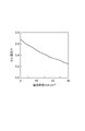
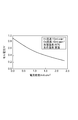
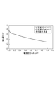
- 10 is a graph showing the results of Example 5.
- 10 is a graph showing the results of Example 5.
- 10 is a graph showing the results of Example 5.
- 10 is a graph showing the results of Example 6.
- 10 is a graph showing the results of Example 7.
- 10 is a schematic cross section which shows an evaluation apparatus.
- 10 is a graph showing the results of Example 8.
- 10 is a graph showing the results of Example 9. It is a
- the layered metal oxide applicable as the electrolyte material is not particularly limited as long as it exhibits hydroxide ion conductivity by steam treatment, but from the viewpoint of achieving a high electromotive force, NaCo is preferable.
- 2 O 4 , LaFe 3 Sr 3 O 10 and Bi 4 Sr 14 Fe 24 O 56 are listed. These materials can be prepared, for example, by a solid phase reaction method.
- the term “layered” as used herein means a crystal structure in which atoms or atomic groups are arranged on a plane to form a sheet structure, and the sheet structure is repeated in a direction perpendicular to the plane.
- NaCo 2 O 4 sodium cobaltate
- NaCo 2 O 4 sodium cobaltate
- a solution in which sodium acetate and cobalt acetate tetrahydrate are dissolved in a predetermined ratio is dried, and the obtained sample is pulverized and temporarily fired. After the pre-baked sample is pulverized, it is fired again at a temperature of about 750 to 850 ° C. in a state of being formed into pellets. Thereafter, the pellets after firing are pulverized and pelletized, and sintered at a temperature of about 900 to 1000 ° C. to obtain NaCo 2 O 4 having a layered crystal structure.
- LaFe 3 Sr 3 O 10 is a perovskite-type layered oxide.
- LaFe 3 Sr 3 O 10 is treated, for example, by putting a predetermined amount of lanthanum oxide, strontium carbonate and iron oxide into a ball mill and mixing the components sufficiently uniformly.
- LaFe 3 Sr 3 O 10 having a layered crystal structure is obtained by molding the obtained sample into pellets and firing at a temperature of about 1400 to 1500 ° C.
- Bi 4 Sr 14 Fe 24 O 56 is treated, for example, by putting a predetermined amount of bismuth oxide, strontium oxide and iron oxide into a ball mill and mixing the components sufficiently uniformly.
- Bi 4 Sr 14 Fe 24 O 56 having a layered crystal structure is obtained by molding the obtained sample into pellets and firing at a temperature of about 1100 to 1200 ° C.
- a powder of NaCo 2 O 4 , LaFe 3 Sr 3 O 10 or Bi 4 Sr 14 Fe 24 O 56 having a layered crystal structure is formed into a desired shape and used as an electrolyte layer of a fuel cell.
- the electrolyte layer contains oxides or impurities other than NaCo 2 O 4 , LaFe 3 Sr 3 O 10 or Bi 4 Sr 14 Fe 24 O 56 to the extent that they do not impair the function of the layered metal oxide. May be.
- FIG. 1 is a schematic cross-sectional view showing the configuration of the fuel cell according to the present embodiment.
- the fuel cell 30 shown in the figure includes a solid electrolyte layer 31 made of a sintered body of NaCo 2 O 4 , an anode 32 and a cathode 33 arranged so as to sandwich the solid electrolyte layer 31, and a solid electrolyte layer 31.
- the space includes a cell main body 35 partitioned into a first region R1 and a second region R2.
- the sintered body of NaCo 2 O 4 forming the solid electrolyte layer 31 can be prepared by compression-molding and firing NaCo 2 O 4 powder. From the viewpoint of achieving high ion conductivity, the solid electrolyte layer 31 preferably has as few voids as possible.
- the thickness of the solid electrolyte layer 31 may be set as appropriate according to the use of the fuel cell, operating conditions, etc., but is preferably 0.02 to 15 mm, more preferably 0.3 to 6 mm. If the thickness of the solid electrolyte layer 31 is less than 0.3 mm, the strength of the solid electrolyte layer 31 tends to be insufficient, and it is necessary to use an anode-supported disk. On the other hand, when the thickness of the solid electrolyte layer 31 exceeds 15 mm, the internal resistance tends to increase.
- the anode 32 is provided on the first region R1 side of the solid electrolyte layer 31, and has a catalyst layer 32a containing Pd and NaCo 2 O 4 .
- the Pd / NaCo 2 O 4 catalyst has a Pd loading of 10 to 20% by mass based on the mass of NaCo 2 O 4 (support). It is preferably 12 to 18% by mass, more preferably 13 to 16% by mass.
- a paste containing a Pd / NaCo 2 O 4 catalyst was applied on the surface F11 on the first region R1 side of the solid electrolyte layer 31, and the paste was dried. Then, it can obtain by baking with an electric furnace.
- the interface between them can be made continuous.
- the cathode 33 is provided on the second region R2 side of the solid electrolyte layer 31.
- the cathode 33 having no catalyst layer is illustrated, but a catalyst layer may be formed on the surface F12 of the solid electrolyte layer 31 on the second region R2 side.
- a catalyst layer made of a Pd / NaCo 2 O 4 catalyst may be formed.
- the cell body 35 accommodates the anode 32, the cathode 33, and the solid electrolyte layer 31, and the internal space is partitioned into the first region R1 and the second region R2 by the solid electrolyte layer 31.
- the cell main body 35 has a gas supply port 35a for supplying hydrogen into the first region R1 and a gas discharge port 35b for discharging gas from the first region R1.
- a pipe 36a and a pipe 36b are connected to the gas supply port 35a and the gas discharge port 35b, respectively.
- a valve (not shown) for adjusting the amount of gas to be supplied is disposed in the middle of the pipe 36a.
- the hydrogen supply means includes a gas supply port 35a, a pipe 36a, a gas amount adjusting valve, and the like.
- the cell body 35 has a gas supply port 35c for supplying oxygen together with moisture into the second region R2 and a gas discharge port 35d for discharging gas from the second region R2.
- a pipe 36c and a pipe 36d are connected to the gas supply port 35c and the gas discharge port 35d, respectively.
- a valve (not shown) for adjusting the amount of gas to be supplied is disposed in the middle of the pipe 36c.
- the oxygen supply means includes a gas supply port 35a, a pipe 36c, a gas amount adjusting valve, and the like.
- Examples of the conductive wires connected to the anode 32 and the cathode 33 include copper wires, nichrome wires, platinum wires, and the like. It is not limited to these conducting wires, and may be appropriately selected according to operating conditions.
- the water vapor treatment of the solid electrolyte layer 31 can be performed, for example, by adjusting the inside of the cell body 35 (the first region R1 and the second region R2) to a predetermined temperature, relative humidity, and pressure.
- the conditions for the steam treatment are not particularly limited as long as the conductivity of the hydroxide ions is expressed, but the following conditions are preferable from the viewpoint of the working efficiency of the steam treatment and the conductivity after the steam treatment. That is, the temperature in the steam treatment is preferably 20 to 150 ° C., more preferably 40 to 130 ° C., and further preferably 50 to 120 ° C.
- the relative humidity in the steam treatment is preferably 30 to 100%, more preferably 40 to 90%, and still more preferably 50 to 90%.
- the pressure in the steam treatment is preferably from 0.1 to 1 MPa, more preferably from 0.1 to 0.8 MPa, and further preferably from 0.2 to 0.5 MPa.
- the treatment time for the steam treatment is preferably 2 to 48 hours, more preferably 3 to 24 hours.
- the hydrogen treatment of the catalyst layer 32a can be performed, for example, by supplying hydrogen in a state where the inside of the first region R1 of the cell body 35 is adjusted to a predetermined temperature and pressure.
- the conditions for hydrotreating are not particularly limited as long as a sufficiently high catalytic activity is exhibited, but the following conditions are preferable from the viewpoints of working efficiency of hydrotreating, catalytic activity after hydrotreating, and the like. That is, the temperature in the hydrogen treatment is preferably 80 to 200 ° C, more preferably 100 to 180 ° C.
- the pressure in the hydrogen treatment is preferably 0.1 to 1 MPa, and more preferably 0.1 to 0.8 MPa.
- the hydrogen concentration in the hydrogen treatment is preferably 10 to 100% by volume, more preferably 20 to 80% by volume.
- the treatment time of the hydrogen treatment is preferably time, and more preferably 3 to 24 hours.
- the reaction represented by the following formula (1) proceeds at the anode by supplying a gas containing H 2 to the first region R1.
- the reaction represented by the following formula (2) proceeds at the cathode.
- the gas supplied to the first region R1 may be hydrogen alone or a mixed gas of hydrogen and an inert gas.
- region R2 should just contain oxygen and a water
- the fuel cell 30 configured as described above has a wide operating temperature range of 10 to 800 ° C. Therefore, the fuel cell 30 can sufficiently generate power at a relatively low temperature condition, for example, 20 to 80 ° C.
- the single-cell fuel cell 30 is illustrated, but a fuel cell stack may be configured by stacking a plurality of cells from the viewpoint of higher output.
- a separator or the like for preventing mixing of supplied hydrogen and oxygen may be provided as appropriate.
- Example 1 In Example 1, the following reagents were used, but other reagents may be used as appropriate. Sodium acetate (CH 3 COONa, Kanto Chemical Special Grade) Cobalt acetate tetrahydrate ((CH 3 COO) 2 Co.4H 2 O, Wako Pure Chemicals Shika Special Grade) Dinitrodiammine palladium (Pd (NO 2 ) 2 (NH 3 ) 2 , Tanaka Kikinzoku) Ethylene glycol (HOCH 2 CH 2 OH, Wako Pure Chemical)
- NaCo 2 O 4 pellets were prepared according to the following procedures (1) to (5).
- the calcined sample was pulverized in an agate mortar and formed into pellets (diameter: 20 mm, thickness: ⁇ 3 mm) using a tablet molding machine (pressure: 30 MPa, holding time: 5 minutes).
- the obtained molded body was placed in a Muffle furnace and baked in air at a temperature of 790 ° C. and a holding time of 3 hours.
- the main-baked sample was placed in a planetary ball mill (FRITSCH pulverisete) and pulverized under conditions of a rotation speed of 300 rpm and a processing time of 20 minutes.
- the obtained powder was put into a tablet molding machine and molded into pellets (diameter: 10 mm, thickness: 1.7-12 mm). In addition, when the thickness of the pellet was 6 mm or less, it was molded under the conditions of a pressure of 30 MPa and a holding time of 5 minutes, and when the thickness of the pellet was about 12 mm, the pressure was 40 MPa and the holding time was 5 minutes.
- the obtained molded body was put in a Muffle furnace and sintered in air at a temperature of 900 ° C. and a holding time of 32 hours to obtain a NaCo 2 O 4 sintered body.
- Radiation source CuK ⁇ Wavelength ⁇ : 0.154056 nm, Tube voltage: 40 kV, Current: 20 mA Measurement range 2 ⁇ : 2-80 °, Scanning axis: 2 ⁇ / ⁇ , Scan step: 0.02 ° Scanning speed: 2 ° / min, Divergent slit: 1/2 ° Scattering slit: 1/2 °, Light receiving slit: 0.15 mm.
- FIG. 2 is an SEM image showing a cross section of a NaCo 2 O 4 pellet in which a catalyst layer (thickness: about 80 ⁇ m) made of a Pd / NaCo 2 O 4 catalyst (Pd support amount 15 mass%) is formed on the surface. .
- LaFe 3 Sr 3 O 10 pellets were prepared according to the following procedures (1) to (5).
- (1) La 2 O 3 3.68 g, SrCO 3 10.00 g, and Fe 2 O 3 5.41 g were mixed with a planetary ball mill at 300 rpm for 30 minutes.
- (2) The obtained powdery solid was molded into pellets (diameter: 20 mm, thickness 2 mm) with a tablet molding machine (JASCO) (pressure: 20 MPa, holding time: 5 minutes).
- JASCO tablet molding machine
- the pellets after molding were air calcined at 1400 ° C.
- Bi 4 Sr 14 Fe 24 O 56 pellets were prepared according to the following procedures (1) to (5).
- (2) The solid on the obtained powder was molded into pellets (diameter: 20 mm, thickness: 2 mm) with a tablet molding machine (JASCO) (pressure: 20 MPa, holding time: 5 minutes).
- JASCO tablet molding machine
- the pellets after molding were air fired at 1100 ° C. for 48 hours (temperature increase rate: 2 K / min).
- Example 4 Power generation test of NaCo 2 O 4 pellet>
- a disk-shaped NaCo 2 O 4 sintered body (diameter 20 mm, thickness 1 mm) was prepared.
- a catalyst layer (diameter 6 mm) was provided in the central portion on one surface of the NaCo 2 O 4 sintered body.
- As the catalyst a NaCo 2 O 4 powder on which 15% by mass of Pd was supported was used.
- the sample produced as described above was attached to the evaluation apparatus shown in FIG. 4 for evaluation.
- Humidified hydrogen can be supplied from below to the surface (anode) having the catalyst layer.
- humidified oxygen can be supplied to the surface (cathode) having no catalyst layer from above.
- the Pt network is disposed on the upper surface and the lower surface of the NaCo 2 O 4 sintered body was measured output from the connected wires (Pt wire) thereto. The measurement was performed according to the following procedure. (1) After mounting the sample on the evaluation apparatus, the pellet was subjected to hydrogen treatment.
- Hydrogen treatment is possible under the conditions of hydrogen concentration 10 to 100% by volume, temperature 80 to 250 ° C., pressure 0.1 to 1 MPa, treatment time 2 to 48 hours, hydrogen concentration 100% volume%, temperature 250 ° C., pressure A condition of 0.1 MPa and a treatment time of 30 minutes after reaching 250 ° C. over 3 hours to increase the temperature is particularly desirable.
- Hydrogen was supplied to the anode (catalyst surface) at 18 mL / min, and oxygen was supplied to the cathode (non-catalyst surface) at 10 mL / min. Then, the portion where the sample was mounted was heated at a temperature rising rate of about 1.4 K / min at 80 to 250 ° C., and then allowed to stand overnight for natural cooling.
- Example 5 After performing the test of Example 4, the evaluation test was performed again without removing the sample from the evaluation device.
- hydrogen was supplied to the anode (catalyst surface) at 5 mL / min, and oxygen was supplied to the cathode (non-catalyst surface) at 10 mL / min. Note that oxygen humidified at a temperature of 80 ° C. was supplied to the cathode. On the other hand, hydrogen was supplied to the anode without being humidified.
- FIG. 5 is a graph showing the temperature dependence of the open circuit voltage (OCV) and the conductivity of hydroxide ions of the samples evaluated in this example.
- FIG. 6 is a graph showing a current / voltage curve under a temperature condition of 75.degree.
- FIG. 7 is a graph plotting values of ion conduction activation energy.
- Example 6 Instead of forming a Pd / NaCo 2 O 4 catalyst layer (Pd loading 15 mass%) only on one side (anode) of the disk-shaped NaCo 2 O 4 sintered body, both NaCo 2 O 4 sintered bodies An evaluation test was conducted in the same manner as in Example 5 except that a Pd / NaCo 2 O 4 catalyst layer (Pd support amount 15% by mass) was formed on the surface.
- FIG. 8 is a graph showing a current / voltage curve under a temperature condition of 75 ° C. In this example, the open circuit voltage (OCV) was 0.86 V, but the current was low. This is thought to be due to insufficient adjustment of the setting conditions.
- OCV open circuit voltage
- FIG. 9 is a schematic diagram showing the configuration of a reactor composed of a quartz tube having an inner diameter of 30 mm.
- the reactor includes a stainless steel tube for flowing a gas and a Teflon sample stage for placing LaFe 3 Sr 3 O 10 pellets (hereinafter sometimes referred to as pellets).
- the reactor mouth was closed with a silicone stopper.
- it was made possible to measure temperature, current, and voltage by passing two silicone wires through two lead wires connected to the respective electrodes of the two thermocouples and the power generation element.
- FIG. 10 is a schematic diagram showing the configuration of the sample stage.
- Teflon PTFE, registered trademark
- a PTFE rod Fraon Industrial Co., Ltd., 35 ⁇ ⁇ 1000 L
- the part A shown in FIG. 10 slides, and the part A is slightly pulled by hand to make a space for putting a sample.
- the pellet can be sandwiched only by the electrode and the thermocouple.
- the A part is fixed with a Teflon screw (PFA) having a heat resistant temperature of 260 ° C.
- PFA Teflon screw
- electrode stainless steel, processing the tip into a needle shape
- Conductive wires connected to the pair of pellet electrodes were connected to EZ Chrom (manufactured by GL Sciences Inc.), and the potential difference was measured.
- FIG. 11 shows an example of the measurement result.
- Example 8 ⁇ Power generation test of LaFe 3 Sr 3 O 10 pellet>
- a disk-shaped LaFe 3 Sr 3 O 10 pellet sintered body (diameter 20 mm, thickness 1 mm) was prepared.
- a catalyst layer (diameter 6 mm) was provided at the central portion on one surface of the LaFe 3 Sr 3 O 10 pellet sintered body.
- a LaFe 3 Sr 3 O 10 powder in which 15% by mass of Pd was supported was used.
- the sample produced as described above was attached to the evaluation apparatus shown in FIG. 12 for evaluation.
- Hydrogen can be supplied from below to the surface (anode) having the catalyst layer.
- humidified oxygen can be supplied to the surface (cathode) having no catalyst layer from above.
- the Pt network is disposed on the upper surface and the lower surface of the LaFe 3 Sr 3 O 10 sintered body was measured output from the connected wires (Pt wire) thereto. The measurement was performed according to the following procedure.
- FIG. 13 shows an example of the measurement result. (1) After mounting the sample on the evaluation apparatus, the pellet was subjected to hydrogen treatment.
- Hydrogen treatment is possible under the conditions of hydrogen concentration 10 to 100% by volume, temperature 80 to 200 ° C., pressure 0.1 to 1 MPa, treatment time 2 to 48 hours, hydrogen concentration 100% volume%, temperature 150 ° C., pressure A condition of 0.1 MPa and a treatment time of 2 hours after reaching 150 ° C. over 3 hours to raise the temperature is particularly desirable.
- the anode (catalyst surface) was supplied with hydrogen that was humidified at 80 ° C. at 10 mL / min, and the cathode (non-catalyst surface) was supplied with oxygen that was humidified at 80 ° C. at 10 mL / min.
- Example 2 In order to evaluate the performance of the fuel cell in the case of using a non-layered metal oxide, Example 4 was used except that yttria-stabilized zirconia (manufactured by Tosoh Corporation) was used as the electrolyte material instead of NaCo 2 O 4. A power generation test was conducted in the same manner as described above. As a result, no potential was generated.
- yttria-stabilized zirconia manufactured by Tosoh Corporation
- Thermogravimetric analysis of NaCo 2 O 4 sample and LaFe 3 Sr 3 O 10 sample was removed by removing the catalyst layer from the NaCo 2 O 4 pellets and LaFe 3 Sr 3 O 10 pellets that were subjected to steam treatment under the same conditions as in the power generation experiments in the above examples. And LaFe 3 Sr 3 O 10 samples were prepared. Using a thermogravimetric analyzer (TG), the weight change of the sample was observed while increasing the temperature from room temperature to 500 ° C. The result is shown in FIG.
- TG thermogravimetric analyzer
- the weight change considered to be caused by the elimination of OH groups in the layered oxide was measured for both the NaCo 2 O 4 sample and the LaFe 3 Sr 3 O 10 sample. That is, since OH group elimination in the layered oxide is considered not to occur at less than 200 ° C., the weight change at 300 to 400 ° C. for the NaCo 2 O 4 sample, and 300 ° C. for the LaFe 3 Sr 3 O 10 sample. It is considered that the weight change in the vicinity is caused by OH group elimination. In other words, it can be said that the OH group present in the layered oxide by the steam treatment is related to the expression of conductivity as a hydroxide ion.
- the temperature range during power generation is preferably lower than the temperature at which weight reduction due to OH group elimination is significant (see FIG. 15).
- the temperature range is preferably 350 ° C. or lower, and more preferably 300 ° C. or lower.
- the temperature range is preferably 300 ° C. or less, and more preferably 250 ° C. or less.
- a sufficiently high electromotive force can be obtained even under a low temperature condition of about room temperature without using deleterious substances or platinum.
- SYMBOLS 30 Fuel cell, 31 ... Solid electrolyte layer, 32 ... Anode, 33 ... Cathode, 35 ... Cell main-body part, 35a ... Gas supply port (hydrogen supply means), 35c ... Gas supply port (oxygen supply means), 36a ... Piping (Hydrogen supply means), 36c ... piping (oxygen supply means), R1 ... first region, R2 ... second region.
Landscapes
- Engineering & Computer Science (AREA)
- Manufacturing & Machinery (AREA)
- Chemical & Material Sciences (AREA)
- Chemical Kinetics & Catalysis (AREA)
- General Chemical & Material Sciences (AREA)
- Electrochemistry (AREA)
- Sustainable Development (AREA)
- Sustainable Energy (AREA)
- Life Sciences & Earth Sciences (AREA)
- Materials Engineering (AREA)
- Inert Electrodes (AREA)
- Fuel Cell (AREA)
- Compounds Of Iron (AREA)
- Inorganic Compounds Of Heavy Metals (AREA)
- Catalysts (AREA)
Abstract
Description
電解質材料として適用可能な層状金属酸化物は、水蒸気処理によって水酸化物イオンの伝導性が発現するものであれば、特に制限はないが、高い起電力を達成する観点から、好ましいものとして、NaCo2O4、LaFe3Sr3O10及びBi4Sr14Fe24O56があげられる。これらの材料は、例えば、固相反応法によって調製することができる。なお、ここでいう層状とは、原子又は原子団が特に平面上に配列してシート構造をつくり、この平面に垂直な方向にシート構造の繰り返しが見られる結晶構造を意味する。
層状金属酸化物を含有する電解質層を備える燃料電池について説明する。ここでは、NaCo2O4の焼結体からなる固体電解質層及びPd/NaCo2O4触媒を具備した燃料電池を例示する。図1は、本実施形態に係る燃料電池の構成を示す模式断面図である。同図に示す燃料電池30は、NaCo2O4の焼結体からなる固体電解質層31と、固体電解質層31を挟むように配置されたアノード32及びカソード33と、固体電解質層31によって内部の空間が第1領域R1及び第2領域R2に仕切られたセル本体部35とを備える。
次に、燃料電池30を用いた発電方法について説明する。固体電解質層31の水酸化物イオンの伝導性を発現させるためには、燃料電池30による発電を開始するに先立ち、固体電解質層31をなすNaCo2O4の水蒸気処理を行う必要がある。固体電解質層31を構成する層状金属酸化物を水蒸気処理することにより、当該層状金属酸化物中の酸素欠陥に水分子が水和する。これによって、水酸化物イオンの伝導性が発現する。燃料電池30は、水酸化物イオン(OH-)が燃料電池のイオン伝導体となることから、アニオン交換型の燃料電池に分類される。
2H2+4OH- → 4H2O+4e- (1)
O2+2H2O+4e- → 4OH- (2)
(実施例1)
実施例1においては、以下の試薬を使用したが、他のものを適宜使用してもよい。
酢酸ナトリウム(CH3COONa、関東化学 特級)
酢酸コバルト四水和物((CH3COO)2Co・4H2O、和光純薬 鹿特級)
ジニトロジアンミンパラジウム(Pd(NO2)2(NH3)2、田中貴金属)
エチレングリコール(HOCH2CH2OH、和光純薬 特級)
NaCo2O4ペレットを以下の(1)~(5)の手順に従って調製した。なお、本実施例においては、NaCo2O4ペレットは、後述の通り、温度900℃程度の焼成過程を経て作製されるものであり、このような高温条件にあっては、Naが蒸発する。したがって、理論量のモル比(Na:Co=1:2)で原料を調製すると、生成物中に不純物(Co3O4)が生じてしまうため、ここでは、原料中のNaとCoのモル比をNa:Co=1.6:2をするとともに、最終的に得られたNaCo2O4ペレットの構造解析を行なった。
(1)酢酸ナトリウム5.00g(60.95mmol)と酢酸コバルト四水和物19.00g(76.28mmol)を内容積200mLのテフロン(登録商標)製のビーカーに秤取し、蒸留水40mLを用いて溶解した。
(2)上記(1)で得た溶液を80℃で撹拌しながら水分を蒸発させ、乾燥機(温度条件:80℃)に入れて、一晩乾燥させた。
(3)乾燥させた試料をメノウ乳鉢でよく粉砕し、これをアルミナるつぼに入れた。このるつぼをMuffle炉に入れ、試料を空気中にて温度750℃、保持時間5時間の条件で仮焼きした。
(4)仮焼きした試料をメノウ乳鉢で粉砕し、錠剤成型器を用いてペレット(直径:20mm、厚さ:~3mm)に成型した(圧力:30MPa、保持時間:5分)。得られた成型体をMuffle炉内に入れ、空気中にて温度790℃、保持時間3時間の条件で本焼きした。
(5)本焼きした試料を遊星型ボールミル(FRITSCH pulverisette)に収容し、回転速度300rpm、処理時間20分の条件で粉砕した。得られた粉体を錠剤成型器に入れてペレット(直径:10mm、厚さ:1.7~12mm)に成型した。なお、ペレットの厚さが6mm以下の場合は、圧力30MPa、保持時間5分、ペレットの厚さが12mm程度の場合は、圧力40MPa、保持時間5分の条件で成型した。得られた成型体をMuffle炉内に入れ、空気中にて温度900℃、保持時間32時間の条件で焼結させ、NaCo2O4の焼結体を得た。
粉末X線回折装置(Rigaku、RINT-Ultima+)を用いて、NaCo2O4の構造解析を行なった。測定条件は以下の通りである。構造解析の結果、調製した試料(NaCo2O4の焼結体)からは不純物(Co3O4)は検出されなかった。
線源:CuKα、
波長λ:0.154056nm、
管電圧:40kV、
電流:20mA、
測定範囲2θ:2~80°、
走査軸:2θ/θ、
スキャンステップ:0.02°、
スキャンスピード:2°/分、
発散スリット:1/2°、
散乱スリット:1/2°、
受光スリット:0.15mm。
NaCo2O4粉末(S=1m2/g)1.0gを蒸発皿に秤量した後、Pd(NH3)2(NO2)2硝酸溶液(4.557質量%)3.87gを更に添加した。これを80℃の水浴上で含浸させ、粉状になるまで水分を蒸発させた。得られた試料をMuffle炉内に入れ、空気中にて温度600℃、保持時間2時間の条件で焼き、NaCo2O4(担体)の質量を基準としたPd担持量が15質量%であるPd/NaCo2O4触媒を得た。
NaCo2O4ペレットの一方面上において、Pd/NaCo2O4触媒10mgとエチレングリコール4μLとをよく練り合わせ、これらを含有するペーストを調製した。このペーストをNaCo2O4ペレットの一方面上に塗りつけた。一方面上に上記ペーストが塗布されたNaCo2O4ペレットを電気炉内に入れ、空気中にて温度400℃、保持時間2時間の条件で焼いた。
走査型電子顕微鏡(SEM、日本電子製、JSM-6300)を用いて、NaCo2O4ペレット及び触媒層の断面を観察した。図2は、Pd/NaCo2O4触媒(Pd担持量15質量%)からなる触媒層(厚さ:約80μm)が表面上に形成されたNaCo2O4ペレットの断面を示すSEM画像である。
<LaFe3Sr3O10ペレットの調製>
LaFe3Sr3O10ペレットを以下の(1)~(5)の手順に従って調製した。
(1)La2O33.68g、SrCO310.00g、Fe2O35.41gを遊星型ボールミルで300rpmで30分間混合した。
(2)得られた粉末状の固体を錠剤成型器(日本分光)でペレット(直径:20mm、厚さ2mmに成型した(圧力:20MPa、保持時間:5分)。
(3)成型後のペレットを1400℃で3時間空気焼成した(昇温速度;~1000℃:10K/分、1000~1400℃:50K/分)。
(4)空冷後、ペレットをアルミナ乳鉢で粉砕した。
(5)得られた粉末状の固体を錠剤成型器(日本分光)でペレット(直径:20mm、厚さ1.25mm)に成型した(圧力:80MPa、保持時間10分)。
NaCo2O4の構造解析と同様に、LaFe3Sr3O10についてもX線回析(XRD)で構造解析を行った。その結果は図3のとおりである。
(1)担体(LaFe3Sr3O101400℃焼成体)0.5gを蒸発皿に秤量し、Pd(NH3)2(NO2)2硝酸溶液(4.557wt%)1.94gを加えた。
(2)これを80℃の水浴上で含浸させ、粉状になるまで水分を蒸発させた。
(3)電気炉において空気中600℃で2時間焼成した。
(1)15wt%Pd/LaFe3Sr3O10を0.010g秤量し、アルミナ乳鉢で粉砕した。
(2)粉砕した粉末にエチレングリコール15μLを加え、ペースト状になるまで混ぜた。
(3)ペーストをLaFe3Sr3O10ペレットに塗布(0.2826g/cm2)した後に、400℃で2時間空気焼成した。
<Bi4Sr14Fe24O56ペレットの調製>
Bi4Sr14Fe24O56ペレットを以下の(1)~(5)の手順に従って調製した。
(1)Bi2O33.728g、SrO5.802g、Fe2O37.665gを遊星型ボールミルで300rpmで30分間混合した。
(2)得られた粉末上の固体を錠剤成型器(日本分光)でペレット(直径:20mm、厚さ:2mm)に成型した(圧力:20MPa、保持時間:5分)。
(3)成型後のペレットを1100℃で48時間空気焼成した(昇温速度:2K/分)。
(4)空冷後、ペレットをアルミナ乳鉢で粉砕した。
(5)得られた粉末状の固体を錠剤成型器(日本分光)でペレット(直径:20mm、厚さ:1.25mm)に成型した(圧力:80MPa、保持時間:10分)。
(1)担体(Bi4Sr14Fe24O561100℃焼成体)0.5gを蒸発皿に秤量し、Pd(NH3)2(NO2)2硝酸溶液(4.557wt%)1.94gを加えた。
(2)これを80℃の水浴上で含浸させ、粉状になるまで水分を蒸発させた。
(3)電気炉で空気中600℃で2時間焼成した。
(1)15wt%Pd/Bi4Sr14Fe24O56を0.010g秤量し、アルミナ乳鉢で粉砕した。
(2)粉砕した粉末にエチレングリコール15μLを加え、ペースト状になるまで混ぜた。
(3)ペーストをBi4Sr14Fe24O56ペレットに0.2826cm2の面積で塗布した後に、400℃で2時間空気焼成した。
<NaCo2O4ペレットの発電試験>
燃料電池の性能を評価するため、ディスク状のNaCo2O4焼結体(直径20mm、厚さ1mm)を準備した。NaCo2O4焼結体の一方面上の中央部分に触媒層(直径6mm)を設けた。触媒として、NaCo2O4粉末にPdを15質量%担持させたものを使用した。
(1)試料を評価装置に装着した後、ペレットの水素処理を行った。水素処理は、水素濃度10~100体積%、温度80~250℃、圧力0.1~1MPa、処理時間2~48時間という条件で可能であり、水素濃度100%体積%、温度250℃、圧力0.1MPa、処理時間として昇温に3時間かけて250℃に達してから30分保持、という条件が特に望ましい。アノード(触媒面)に水素を18mL/分で供給するとともに、カソード(非触媒面)に酸素を10mL/分で供給した。そして、試料が装着された部分を約1.4K/分の昇温レートで80~250℃で加熱した後、一晩放置して自然冷却した。
(2)水素処理後のペレットに対して水蒸気処理を施した。水蒸気処理は、温度20~150℃、相対湿度30~100%、圧力0.1~1MPa、処理時間2~48時間という条件で可能であり、温度60℃、相対湿度100%、圧力0.1MPa、処理時間3時間という条件が特に望ましい。アノード(触媒面)に水素を46mL/分で供給するとともに、カソード(非触媒面)に酸素を25mL/分で供給した。なお、温度条件80℃にて加湿した水素及び酸素をアノード及びカソードにそれぞれ供給した。そして、試料が装着された部分の温度が60℃となるように調節しながら、2時間測定を行った。
本実施例においては、開回路電圧(OCV)の値が600mVであった。
上記実施例4の試験を行った後、評価装置から試料を取り外すことなく、再度、評価試験を行った。本実施例においては、アノード(触媒面)に水素を5mL/分で供給するとともに、カソード(非触媒面)に酸素を10mL/分で供給した。なお、温度条件80℃にて加湿した酸素をカソードに供給した。一方、水素は加湿することなく、アノードに供給した。
ディスク状のNaCo2O4焼結体の一方面(アノード)のみにPd/NaCo2O4触媒層(Pd担持量15質量%)を形成する代わりに、NaCo2O4焼結体の両方の面にPd/NaCo2O4触媒層(Pd担持量15質量%)を形成したことの他は、実施例5と同様にして評価試験を行った。図8は、温度条件75℃における電流・電圧曲線を示すグラフである。本実施例においては、開回路電圧(OCV)は0.86Vであったが、電流は低い値であった。設定条件の調整が不十分であったためと考えられる。
<LaFe3Sr3O10ペレットの単室燃料電池による発電試験>
図9は、内径30mmの石英管からなる反応器の構成を示す模式図である。当該反応器は、ガスを流すためのステンレス管と、LaFe3Sr3O10ペレット(以下、ペレットということがある)を載置するためのテフロン製の試料台とを備える。反応器の口は、シリコーン栓で塞いだ。なお、2本の熱電対及び発電素子のそれぞれの電極につながる2本の導線がシリコーン栓を貫通させることで、温度と電流・電圧を測定できるようにした。
<LaFe3Sr3O10ペレットの発電試験>
図12に示す構成の燃料電池の性能を評価するため、ディスク状のLaFe3Sr3O10ペレット焼結体(直径20mm、厚さ1mm)を準備した。LaFe3Sr3O10ペレット焼結体の一方面上の中央部分に触媒層(直径6mm)を設けた。触媒として、LaFe3Sr3O10粉末にPdを15質量%担持させたものを使用した。
(1)試料を評価装置に装着した後、ペレットの水素処理を行った。水素処理は、水素濃度10~100体積%、温度80~200℃、圧力0.1~1MPa、処理時間2~48時間という条件で可能であり、水素濃度100%体積%、温度150℃、圧力0.1MPa、処理時間として昇温に3時間かけて150℃に達してから2時間保持、という条件が特に望ましい。
(2)水素処理後のペレットに対して水蒸気処理を施した。水蒸気処理は、温度20~150℃、相対湿度30~100%、圧力0.1~1MPa、処理時間2~48時間という条件で可能であり、温度25℃(室温)、相対湿度100%、圧力0.1MPa、処理時間3時間という条件が特に望ましい。アノード(触媒面)に水素を10mL/分で80℃加湿されたものを供給するとともに、カソード(非触媒面)に酸素を10mL/分で80℃加湿されたものを供給した。
<Bi4Sr14Fe24O56ペレットの燃料電池による発電試験>
ペレットの両面を湿らせ、カソードガス:O2=10mL/分、アノードガス:H2=10mL分を流し、図12で示したものと同様の装置を用いて発電試験を行い、図14に測定結果の一例を示した。
NaCo2O4ペレットに水蒸気処理をしない場合の燃料電池の性能を評価するため、水蒸気処理を実施しなかったことの他は実施例4と同様にして、発電試験を実施した。その結果、温度条件0~200℃の範囲では電位が発生しなかった。
層状ではない金属酸化物を使用した場合の燃料電池の性能を評価するため、NaCo2O4の代わりにイットリア安定化ジルコニア(東ソー(株)製)を電解質材料としたことの他は実施例4と同様にして、発電試験を実施した。その結果、電位が発生しなかった。
上記実施例における発電実験と同様の条件で水蒸気処理を施し、発電に使用したNaCo2O4ペレット及びLaFe3Sr3O10ペレットから、触媒層をはがし、熱重量分析用のNaCo2O4試料及びLaFe3Sr3O10試料を準備した。熱重量分析装置(TG)を用いて、室温から500℃まで温度を上昇させながら、試料の重量変化を観測した。その結果を図15に示す。
Claims (5)
- 水蒸気処理が施された層状金属酸化物を含有する電解質層を備える燃料電池。
- 水蒸気処理が施された層状金属酸化物を含有する電解質層と、
前記電解質層によって内部の空間が第1領域及び第2領域に仕切られたセル本体部と、
前記電解質層の前記第1領域側に設けられ、Pd及び前記層状金属酸化物を含有する触媒層を有するアノードと、
前記電解質層の前記第2領域側に設けられたカソードと、
前記第1領域に水素を供給する水素供給手段と、
前記第2領域に水分とともに酸素を供給する酸素供給手段と、
を備える燃料電池。 - 前記電解質層は、NaCo2O4、LaFe3Sr3O10及びBi4Sr14Fe24O56からなる群より選択される一種の層状金属酸化物を含有する、請求項1又は2に記載の燃料電池。
- 層状金属酸化物を含有する電解質層と、前記電解質層によって内部の空間が第1領域及び第2領域に仕切られたセル本体部と、前記電解質層の前記第1領域側に設けられ、Pd及び前記層状金属酸化物を含有する触媒層を有するアノードと、前記電解質層の前記第2領域側に設けられたカソードを備える燃料電池を用いた発電方法であって、
前記電解質層に含まれる前記層状金属酸化物を水蒸気処理する工程と、
前記第1領域に水素を供給し、前記第2領域に水分とともに酸素を供給する工程と、
を備える発電方法。 - 前記電解質層は、NaCo2O4、LaFe3Sr3O10及びBi4Sr14Fe24O56からなる群より選択される一種の層状金属酸化物を含有する、請求項4に記載の発電方法。
Priority Applications (5)
| Application Number | Priority Date | Filing Date | Title |
|---|---|---|---|
| US13/054,032 US8962217B2 (en) | 2008-07-15 | 2009-07-10 | Fuel cell and electricity generation method using the same |
| JP2010520848A JP5376605B2 (ja) | 2008-07-15 | 2009-07-10 | 燃料電池及びこれを用いた発電方法 |
| CN2009801277644A CN102099951B (zh) | 2008-07-15 | 2009-07-10 | 燃料电池及使用该燃料电池的发电方法 |
| EP09797874.6A EP2306569B1 (en) | 2008-07-15 | 2009-07-10 | Fuel cell and electricity generation method using the same |
| CA2730791A CA2730791C (en) | 2008-07-15 | 2009-07-10 | Fuel cell and electricity generation method using the same |
Applications Claiming Priority (4)
| Application Number | Priority Date | Filing Date | Title |
|---|---|---|---|
| JP2008184213 | 2008-07-15 | ||
| JP2008-184213 | 2008-07-15 | ||
| JP2008317575 | 2008-12-12 | ||
| JP2008-317575 | 2008-12-12 |
Publications (1)
| Publication Number | Publication Date |
|---|---|
| WO2010007949A1 true WO2010007949A1 (ja) | 2010-01-21 |
Family
ID=41550352
Family Applications (1)
| Application Number | Title | Priority Date | Filing Date |
|---|---|---|---|
| PCT/JP2009/062608 Ceased WO2010007949A1 (ja) | 2008-07-15 | 2009-07-10 | 燃料電池及びこれを用いた発電方法 |
Country Status (7)
| Country | Link |
|---|---|
| US (1) | US8962217B2 (ja) |
| EP (1) | EP2306569B1 (ja) |
| JP (1) | JP5376605B2 (ja) |
| KR (1) | KR20110049791A (ja) |
| CN (1) | CN102099951B (ja) |
| CA (1) | CA2730791C (ja) |
| WO (1) | WO2010007949A1 (ja) |
Cited By (9)
| Publication number | Priority date | Publication date | Assignee | Title |
|---|---|---|---|---|
| JP2011108574A (ja) * | 2009-11-20 | 2011-06-02 | Fuji Electric Holdings Co Ltd | 固体電解質形燃料電池およびその製造方法 |
| JP2011124020A (ja) * | 2009-12-08 | 2011-06-23 | Fuji Electric Co Ltd | 固体電解質形燃料電池およびその製造方法 |
| WO2011108526A1 (ja) | 2010-03-02 | 2011-09-09 | 株式会社三徳 | 固体電解質膜、燃料電池用セル及び燃料電池 |
| JP2012164609A (ja) * | 2011-02-09 | 2012-08-30 | Toyota Motor Corp | 層状金属酸化物を含む電極及び固体電解質層を備える燃料電池 |
| JP2012164610A (ja) * | 2011-02-09 | 2012-08-30 | Toyota Motor Corp | 層状金属酸化物を含む固体電解質及びその製造方法 |
| WO2012176749A1 (ja) | 2011-06-20 | 2012-12-27 | 株式会社三徳 | 固体電解質、固体電解質膜、燃料電池用セル及び燃料電池 |
| JP2014002845A (ja) * | 2012-06-15 | 2014-01-09 | Fuji Electric Co Ltd | 燃料電池発電装置およびその運転方法 |
| JP2014049270A (ja) * | 2012-08-31 | 2014-03-17 | Ti:Kk | 燃料電池 |
| US8986894B2 (en) | 2011-02-09 | 2015-03-24 | Toyota Jidosha Kabushiki Kaisha | Solid electrolyte including layered metal oxide, fuel cell including thereof, production method for solid electrolyte, and production method for electrode catalyst |
Families Citing this family (3)
| Publication number | Priority date | Publication date | Assignee | Title |
|---|---|---|---|---|
| JP6206971B2 (ja) * | 2012-04-26 | 2017-10-04 | 日本碍子株式会社 | リチウム空気二次電池 |
| JP5961709B2 (ja) * | 2013-01-30 | 2016-08-02 | 富士電機株式会社 | 正極触媒、及び機器 |
| CN114367290A (zh) * | 2021-12-29 | 2022-04-19 | 西南科技大学 | 一种放射性去污可剥离膜热敏降解催化剂的制备及应用方法 |
Citations (7)
| Publication number | Priority date | Publication date | Assignee | Title |
|---|---|---|---|---|
| JPH09501722A (ja) | 1993-08-23 | 1997-02-18 | アルトマイアー,パトリック | 強塩基性アニオン交換膜及びその製造方法 |
| JP2004224862A (ja) | 2003-01-21 | 2004-08-12 | Tokuyama Corp | イオン交換膜 |
| JP2005067915A (ja) * | 2003-08-27 | 2005-03-17 | Japan Science & Technology Agency | プロトン・電子混合伝導体及びその製造法と用途 |
| JP2006244961A (ja) | 2005-03-07 | 2006-09-14 | Daihatsu Motor Co Ltd | 燃料電池 |
| JP2008504660A (ja) | 2004-07-02 | 2008-02-14 | ソルヴェイ(ソシエテ アノニム) | イオン交換膜を含む固体アルカリ型燃料電池 |
| WO2008120675A1 (ja) * | 2007-03-30 | 2008-10-09 | Tokuyama Corporation | 直接液体燃料型燃料電池用隔膜およびその製造方法 |
| JP2009140783A (ja) * | 2007-12-07 | 2009-06-25 | Tokuyama Corp | ガス拡散電極用水酸化物イオン伝導性付与剤 |
Family Cites Families (8)
| Publication number | Priority date | Publication date | Assignee | Title |
|---|---|---|---|---|
| JPH11144745A (ja) | 1997-11-06 | 1999-05-28 | Asahi Glass Co Ltd | 固体高分子電解質型メタノール燃料電池 |
| JP3737299B2 (ja) | 1998-12-03 | 2006-01-18 | 東京瓦斯株式会社 | 熱電変換方法及び装置 |
| US7045231B2 (en) * | 2002-05-22 | 2006-05-16 | Protonetics International, Inc. | Direct hydrocarbon reforming in protonic ceramic fuel cells by electrolyte steam permeation |
| CA2452657C (en) * | 2003-02-18 | 2009-03-03 | Sulzer Markets And Technology Ag | A power source with solid oxide fuel cells |
| WO2006113469A1 (en) * | 2005-04-14 | 2006-10-26 | H2Volt, Inc. | Integrated fuel and fuel cell device |
| WO2007060925A1 (ja) * | 2005-11-24 | 2007-05-31 | Japan Science & Technology Agency | 電気化学セル及び電気化学セルの製造方法 |
| WO2008033452A2 (en) * | 2006-09-13 | 2008-03-20 | Ceramatec, Inc. | High purity hydrogen and electric power co-generation apparatus and method |
| US8986894B2 (en) * | 2011-02-09 | 2015-03-24 | Toyota Jidosha Kabushiki Kaisha | Solid electrolyte including layered metal oxide, fuel cell including thereof, production method for solid electrolyte, and production method for electrode catalyst |
-
2009
- 2009-07-10 WO PCT/JP2009/062608 patent/WO2010007949A1/ja not_active Ceased
- 2009-07-10 CN CN2009801277644A patent/CN102099951B/zh not_active Expired - Fee Related
- 2009-07-10 JP JP2010520848A patent/JP5376605B2/ja not_active Expired - Fee Related
- 2009-07-10 EP EP09797874.6A patent/EP2306569B1/en not_active Not-in-force
- 2009-07-10 CA CA2730791A patent/CA2730791C/en not_active Expired - Fee Related
- 2009-07-10 US US13/054,032 patent/US8962217B2/en not_active Expired - Fee Related
- 2009-07-10 KR KR1020117002973A patent/KR20110049791A/ko not_active Ceased
Patent Citations (7)
| Publication number | Priority date | Publication date | Assignee | Title |
|---|---|---|---|---|
| JPH09501722A (ja) | 1993-08-23 | 1997-02-18 | アルトマイアー,パトリック | 強塩基性アニオン交換膜及びその製造方法 |
| JP2004224862A (ja) | 2003-01-21 | 2004-08-12 | Tokuyama Corp | イオン交換膜 |
| JP2005067915A (ja) * | 2003-08-27 | 2005-03-17 | Japan Science & Technology Agency | プロトン・電子混合伝導体及びその製造法と用途 |
| JP2008504660A (ja) | 2004-07-02 | 2008-02-14 | ソルヴェイ(ソシエテ アノニム) | イオン交換膜を含む固体アルカリ型燃料電池 |
| JP2006244961A (ja) | 2005-03-07 | 2006-09-14 | Daihatsu Motor Co Ltd | 燃料電池 |
| WO2008120675A1 (ja) * | 2007-03-30 | 2008-10-09 | Tokuyama Corporation | 直接液体燃料型燃料電池用隔膜およびその製造方法 |
| JP2009140783A (ja) * | 2007-12-07 | 2009-06-25 | Tokuyama Corp | ガス拡散電極用水酸化物イオン伝導性付与剤 |
Non-Patent Citations (1)
| Title |
|---|
| See also references of EP2306569A4 |
Cited By (18)
| Publication number | Priority date | Publication date | Assignee | Title |
|---|---|---|---|---|
| JP2011108574A (ja) * | 2009-11-20 | 2011-06-02 | Fuji Electric Holdings Co Ltd | 固体電解質形燃料電池およびその製造方法 |
| JP2011124020A (ja) * | 2009-12-08 | 2011-06-23 | Fuji Electric Co Ltd | 固体電解質形燃料電池およびその製造方法 |
| WO2011108526A1 (ja) | 2010-03-02 | 2011-09-09 | 株式会社三徳 | 固体電解質膜、燃料電池用セル及び燃料電池 |
| CN102870263B (zh) * | 2010-03-02 | 2016-08-03 | 株式会社三德 | 固体电解质隔膜、燃料电池单元及燃料电池 |
| US9318765B2 (en) | 2010-03-02 | 2016-04-19 | Santoku Corporation | Solid electrolyte membrane, fuel battery cell, and fuel battery |
| JP5780656B2 (ja) * | 2010-03-02 | 2015-09-16 | 株式会社三徳 | 固体電解質膜、燃料電池用セル及び燃料電池 |
| US20120328971A1 (en) * | 2010-03-02 | 2012-12-27 | National Univ. Corporation Hokkaido Univ. | Solid electrolyte membrane, fuel battery cell, and fuel battery |
| CN102870263A (zh) * | 2010-03-02 | 2013-01-09 | 株式会社三德 | 固体电解质隔膜、燃料电池单元及燃料电池 |
| US8986894B2 (en) | 2011-02-09 | 2015-03-24 | Toyota Jidosha Kabushiki Kaisha | Solid electrolyte including layered metal oxide, fuel cell including thereof, production method for solid electrolyte, and production method for electrode catalyst |
| JP2012164610A (ja) * | 2011-02-09 | 2012-08-30 | Toyota Motor Corp | 層状金属酸化物を含む固体電解質及びその製造方法 |
| JP2012164609A (ja) * | 2011-02-09 | 2012-08-30 | Toyota Motor Corp | 層状金属酸化物を含む電極及び固体電解質層を備える燃料電池 |
| KR20140068001A (ko) | 2011-06-20 | 2014-06-05 | 가부시키가이샤 산도쿠 | 고체 전해질, 고체 전해질 막, 연료전지용 셀 및 연료전지 |
| JPWO2012176749A1 (ja) * | 2011-06-20 | 2015-02-23 | 株式会社三徳 | 固体電解質、固体電解質膜、燃料電池用セル及び燃料電池 |
| WO2012176749A1 (ja) | 2011-06-20 | 2012-12-27 | 株式会社三徳 | 固体電解質、固体電解質膜、燃料電池用セル及び燃料電池 |
| US9590261B2 (en) | 2011-06-20 | 2017-03-07 | Santoku Corporation | Solid electrolyte, solid electrolyte membrane, fuel battery cell, and fuel battery |
| KR101925377B1 (ko) | 2011-06-20 | 2019-02-27 | 가부시키가이샤 산도쿠 | 고체 전해질, 고체 전해질 막, 연료전지용 셀 및 연료전지 |
| JP2014002845A (ja) * | 2012-06-15 | 2014-01-09 | Fuji Electric Co Ltd | 燃料電池発電装置およびその運転方法 |
| JP2014049270A (ja) * | 2012-08-31 | 2014-03-17 | Ti:Kk | 燃料電池 |
Also Published As
| Publication number | Publication date |
|---|---|
| EP2306569A1 (en) | 2011-04-06 |
| JP5376605B2 (ja) | 2013-12-25 |
| EP2306569B1 (en) | 2015-12-16 |
| CN102099951A (zh) | 2011-06-15 |
| CA2730791A1 (en) | 2010-01-21 |
| US20110143259A1 (en) | 2011-06-16 |
| CA2730791C (en) | 2017-08-29 |
| JPWO2010007949A1 (ja) | 2012-01-05 |
| US8962217B2 (en) | 2015-02-24 |
| CN102099951B (zh) | 2013-08-07 |
| KR20110049791A (ko) | 2011-05-12 |
| EP2306569A4 (en) | 2011-08-17 |
Similar Documents
| Publication | Publication Date | Title |
|---|---|---|
| JP5376605B2 (ja) | 燃料電池及びこれを用いた発電方法 | |
| JP5780656B2 (ja) | 固体電解質膜、燃料電池用セル及び燃料電池 | |
| Fan et al. | Infiltration of La0· 6Sr0· 4FeO3-δ nanoparticles into YSZ scaffold for solid oxide fuel cell and solid oxide electrolysis cell | |
| Li et al. | Sr2Fe2− xMoxO6− δ perovskite as an anode in a solid oxide fuel cell: Effect of the substitution ratio | |
| Lenka et al. | Comparative investigation on the functional properties of alkaline earth metal (Ca, Ba, Sr) doped Nd2NiO4+ δ oxygen electrode material for SOFC applications | |
| EP2637243B1 (en) | Inorganic ion conductor, method of forming the same, and fuel cell including the inorganic ion conductor | |
| US20240387842A1 (en) | Power-generating element, power-generating apparatus, and power-generating method | |
| Ju et al. | Phase transition of doped LaFeO3 anode in reducing atmosphere and their power generation property in intermediate temperature solid oxide fuel cell | |
| Liao et al. | Synthesis and characterization of Ga-doped Ba3MoNbO8. 5 electrolytes for intermediate temperature-solid oxide fuel cells | |
| JP4534188B2 (ja) | 燃料電池用電極材料及びこれを用いた固体酸化物形燃料電池 | |
| CN103548191A (zh) | 固体氧化物型燃料电池单电池及固体氧化物型燃料电池单电池的制造方法 | |
| Tang et al. | Understanding the catalysis of noble metals in reduction of iron oxide by hydrogen: insights from DFT calculations | |
| Liu et al. | Accelerated proton exchange kinetics and poisoning resistance of La0. 8Sr0. 2Co0. 2Fe0. 8O3-δ through high-entropy engineering strategies | |
| JP6625855B2 (ja) | 水蒸気電解用セルおよびその製造方法 | |
| JP5531297B2 (ja) | Fe、Co及びNiを含む電極触媒及びその製造方法 | |
| JP6367636B2 (ja) | 水蒸気電解用セル | |
| CN103199265A (zh) | 一种中低温质子传输固体氧化物燃料电池的复合阴极材料 | |
| CN103748721B (zh) | 固体电解质、固体电解质膜、燃料电池单元以及燃料电池 | |
| Feng et al. | Highly enhanced performance of La0. 8Sr0. 2MnO3-δ cathode by compositing with (Er0. 25Ce0. 05Bi0. 7) 2O3+ δ for low-temperature solid oxide fuel cells | |
| KR20250068014A (ko) | 프로토닉 세라믹 전기화학 전지의 공기극용 소재 및 이를 포함하는 프로토닉 세라믹 전기화학 전지 | |
| Sornthummalee et al. | Thermochemical Stability and Polarization Resistance of La (Ni0. 6Fe0. 4) O3 Cathode | |
| SA | Development of Doped Ceria-Carbonate-Based Composite Electrolyte and Lanthanum Strontium-Based Cathode for Solid Oxide Fuel Cells | |
| WO2016017251A1 (ja) | 水蒸気電解用セル |
Legal Events
| Date | Code | Title | Description |
|---|---|---|---|
| WWE | Wipo information: entry into national phase |
Ref document number: 200980127764.4 Country of ref document: CN |
|
| 121 | Ep: the epo has been informed by wipo that ep was designated in this application |
Ref document number: 09797874 Country of ref document: EP Kind code of ref document: A1 |
|
| WWE | Wipo information: entry into national phase |
Ref document number: 2010520848 Country of ref document: JP |
|
| ENP | Entry into the national phase |
Ref document number: 2730791 Country of ref document: CA |
|
| NENP | Non-entry into the national phase |
Ref country code: DE |
|
| WWE | Wipo information: entry into national phase |
Ref document number: 2009797874 Country of ref document: EP |
|
| ENP | Entry into the national phase |
Ref document number: 20117002973 Country of ref document: KR Kind code of ref document: A |
|
| WWE | Wipo information: entry into national phase |
Ref document number: 13054032 Country of ref document: US |