WO2010008026A2 - 電池パック - Google Patents
電池パック Download PDFInfo
- Publication number
- WO2010008026A2 WO2010008026A2 PCT/JP2009/062829 JP2009062829W WO2010008026A2 WO 2010008026 A2 WO2010008026 A2 WO 2010008026A2 JP 2009062829 W JP2009062829 W JP 2009062829W WO 2010008026 A2 WO2010008026 A2 WO 2010008026A2
- Authority
- WO
- WIPO (PCT)
- Prior art keywords
- battery
- battery pack
- unit
- voltage detection
- circuit board
- Prior art date
- Legal status (The legal status is an assumption and is not a legal conclusion. Google has not performed a legal analysis and makes no representation as to the accuracy of the status listed.)
- Ceased
Links
Images


Classifications
-
- H—ELECTRICITY
- H01—ELECTRIC ELEMENTS
- H01M—PROCESSES OR MEANS, e.g. BATTERIES, FOR THE DIRECT CONVERSION OF CHEMICAL ENERGY INTO ELECTRICAL ENERGY
- H01M10/00—Secondary cells; Manufacture thereof
- H01M10/42—Methods or arrangements for servicing or maintenance of secondary cells or secondary half-cells
- H01M10/425—Structural combination with electronic components, e.g. electronic circuits integrated to the outside of the casing
-
- H—ELECTRICITY
- H02—GENERATION; CONVERSION OR DISTRIBUTION OF ELECTRIC POWER
- H02J—ELECTRIC POWER NETWORKS; CIRCUIT ARRANGEMENTS OR SYSTEMS FOR SUPPLYING OR DISTRIBUTING ELECTRIC POWER; SYSTEMS FOR STORING ELECTRIC ENERGY
- H02J7/00—Circuit arrangements for charging or discharging batteries or for supplying loads from batteries
- H02J7/60—Circuit arrangements for charging or discharging batteries or for supplying loads from batteries including safety or protection arrangements
- H02J7/61—Circuit arrangements for charging or discharging batteries or for supplying loads from batteries including safety or protection arrangements against overcharge
-
- H—ELECTRICITY
- H02—GENERATION; CONVERSION OR DISTRIBUTION OF ELECTRIC POWER
- H02J—ELECTRIC POWER NETWORKS; CIRCUIT ARRANGEMENTS OR SYSTEMS FOR SUPPLYING OR DISTRIBUTING ELECTRIC POWER; SYSTEMS FOR STORING ELECTRIC ENERGY
- H02J7/00—Circuit arrangements for charging or discharging batteries or for supplying loads from batteries
- H02J7/60—Circuit arrangements for charging or discharging batteries or for supplying loads from batteries including safety or protection arrangements
- H02J7/62—Circuit arrangements for charging or discharging batteries or for supplying loads from batteries including safety or protection arrangements against overcurrent
-
- H—ELECTRICITY
- H02—GENERATION; CONVERSION OR DISTRIBUTION OF ELECTRIC POWER
- H02J—ELECTRIC POWER NETWORKS; CIRCUIT ARRANGEMENTS OR SYSTEMS FOR SUPPLYING OR DISTRIBUTING ELECTRIC POWER; SYSTEMS FOR STORING ELECTRIC ENERGY
- H02J7/00—Circuit arrangements for charging or discharging batteries or for supplying loads from batteries
- H02J7/60—Circuit arrangements for charging or discharging batteries or for supplying loads from batteries including safety or protection arrangements
- H02J7/63—Circuit arrangements for charging or discharging batteries or for supplying loads from batteries including safety or protection arrangements against overdischarge
-
- H—ELECTRICITY
- H02—GENERATION; CONVERSION OR DISTRIBUTION OF ELECTRIC POWER
- H02J—ELECTRIC POWER NETWORKS; CIRCUIT ARRANGEMENTS OR SYSTEMS FOR SUPPLYING OR DISTRIBUTING ELECTRIC POWER; SYSTEMS FOR STORING ELECTRIC ENERGY
- H02J7/00—Circuit arrangements for charging or discharging batteries or for supplying loads from batteries
- H02J7/60—Circuit arrangements for charging or discharging batteries or for supplying loads from batteries including safety or protection arrangements
- H02J7/65—Circuit arrangements for charging or discharging batteries or for supplying loads from batteries including safety or protection arrangements against overtemperature
-
- H—ELECTRICITY
- H02—GENERATION; CONVERSION OR DISTRIBUTION OF ELECTRIC POWER
- H02J—ELECTRIC POWER NETWORKS; CIRCUIT ARRANGEMENTS OR SYSTEMS FOR SUPPLYING OR DISTRIBUTING ELECTRIC POWER; SYSTEMS FOR STORING ELECTRIC ENERGY
- H02J7/00—Circuit arrangements for charging or discharging batteries or for supplying loads from batteries
- H02J7/70—Circuit arrangements for charging or discharging batteries or for supplying loads from batteries characterised by the mechanical construction
-
- H—ELECTRICITY
- H01—ELECTRIC ELEMENTS
- H01M—PROCESSES OR MEANS, e.g. BATTERIES, FOR THE DIRECT CONVERSION OF CHEMICAL ENERGY INTO ELECTRICAL ENERGY
- H01M2200/00—Safety devices for primary or secondary batteries
- H01M2200/10—Temperature sensitive devices
- H01M2200/103—Fuse
-
- H—ELECTRICITY
- H01—ELECTRIC ELEMENTS
- H01M—PROCESSES OR MEANS, e.g. BATTERIES, FOR THE DIRECT CONVERSION OF CHEMICAL ENERGY INTO ELECTRICAL ENERGY
- H01M50/00—Constructional details or processes of manufacture of the non-active parts of electrochemical cells other than fuel cells, e.g. hybrid cells
- H01M50/10—Primary casings; Jackets or wrappings
- H01M50/102—Primary casings; Jackets or wrappings characterised by their shape or physical structure
- H01M50/103—Primary casings; Jackets or wrappings characterised by their shape or physical structure prismatic or rectangular
-
- H—ELECTRICITY
- H01—ELECTRIC ELEMENTS
- H01M—PROCESSES OR MEANS, e.g. BATTERIES, FOR THE DIRECT CONVERSION OF CHEMICAL ENERGY INTO ELECTRICAL ENERGY
- H01M50/00—Constructional details or processes of manufacture of the non-active parts of electrochemical cells other than fuel cells, e.g. hybrid cells
- H01M50/20—Mountings; Secondary casings or frames; Racks, modules or packs; Suspension devices; Shock absorbers; Transport or carrying devices; Holders
- H01M50/204—Racks, modules or packs for multiple batteries or multiple cells
- H01M50/207—Racks, modules or packs for multiple batteries or multiple cells characterised by their shape
- H01M50/211—Racks, modules or packs for multiple batteries or multiple cells characterised by their shape adapted for pouch cells
-
- H—ELECTRICITY
- H02—GENERATION; CONVERSION OR DISTRIBUTION OF ELECTRIC POWER
- H02J—ELECTRIC POWER NETWORKS; CIRCUIT ARRANGEMENTS OR SYSTEMS FOR SUPPLYING OR DISTRIBUTING ELECTRIC POWER; SYSTEMS FOR STORING ELECTRIC ENERGY
- H02J7/00—Circuit arrangements for charging or discharging batteries or for supplying loads from batteries
- H02J7/50—Circuit arrangements for charging or discharging batteries or for supplying loads from batteries acting upon multiple batteries simultaneously or sequentially
-
- Y—GENERAL TAGGING OF NEW TECHNOLOGICAL DEVELOPMENTS; GENERAL TAGGING OF CROSS-SECTIONAL TECHNOLOGIES SPANNING OVER SEVERAL SECTIONS OF THE IPC; TECHNICAL SUBJECTS COVERED BY FORMER USPC CROSS-REFERENCE ART COLLECTIONS [XRACs] AND DIGESTS
- Y02—TECHNOLOGIES OR APPLICATIONS FOR MITIGATION OR ADAPTATION AGAINST CLIMATE CHANGE
- Y02E—REDUCTION OF GREENHOUSE GAS [GHG] EMISSIONS, RELATED TO ENERGY GENERATION, TRANSMISSION OR DISTRIBUTION
- Y02E60/00—Enabling technologies; Technologies with a potential or indirect contribution to GHG emissions mitigation
- Y02E60/10—Energy storage using batteries
-
- Y—GENERAL TAGGING OF NEW TECHNOLOGICAL DEVELOPMENTS; GENERAL TAGGING OF CROSS-SECTIONAL TECHNOLOGIES SPANNING OVER SEVERAL SECTIONS OF THE IPC; TECHNICAL SUBJECTS COVERED BY FORMER USPC CROSS-REFERENCE ART COLLECTIONS [XRACs] AND DIGESTS
- Y02—TECHNOLOGIES OR APPLICATIONS FOR MITIGATION OR ADAPTATION AGAINST CLIMATE CHANGE
- Y02T—CLIMATE CHANGE MITIGATION TECHNOLOGIES RELATED TO TRANSPORTATION
- Y02T10/00—Road transport of goods or passengers
- Y02T10/60—Other road transportation technologies with climate change mitigation effect
- Y02T10/70—Energy storage systems for electromobility, e.g. batteries
Definitions
- the present invention relates to a battery pack composed of battery modules suitable for multi-series multi-parallel connection with secondary batteries.
- a lithium ion secondary battery includes a positive electrode formed by forming a positive electrode active material layer made of a positive electrode active material powder such as lithium cobalt composite oxide, a conductive powder, and a binder on a surface of a positive electrode current collector made of an aluminum foil, carbon
- a negative electrode formed by forming a negative electrode active material layer made of a binder and a negative electrode active material layer made of a binder on the surface of a negative electrode current collector made of copper foil is stacked with a separator made of a porous synthetic resin film, and an electrolyte solution The battery element is impregnated.
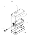
- FIG. 6 is a diagram illustrating an example of a conventional battery pack.
- the battery pack shown in FIG. 6 is a large-capacity lithium ion battery pack composed of seven unit batteries.
- a protection circuit board 7 is attached to a battery pack 4 in which unit cells having a capacity of about 4.0 Ah are arranged in 7 series and 1 parallel in the first casing piece 3a and the second lid piece 3b. It is provided with a connector 8 for connection to the outside.
- FIG. 7 is a diagram for explaining another example of a conventional battery pack.
- the battery pack shown in FIG. 7 is a large-capacity lithium ion battery pack composed of 14 conventional unit batteries.
- battery packs 4a and 4b in which unit cells having a capacity of about 1.0 Ah are arranged in parallel in 7 series and 1 parallel in the first housing piece 3a and the second housing piece 3b are connected in parallel.
- 7 is arranged in series and 2 in parallel, and a protective circuit board 7 is attached, and a connector 8 for connection to the outside is provided.
- a battery pack in which a plurality of battery modules each containing a plurality of unit batteries are provided inside a housing instead of a unit battery directly disposed in a battery pack.
- battery packs with various electrical outputs can be efficiently assembled by combining various battery modules.
- the battery module is also provided with a protective circuit board for the assembled battery in which unit cells are connected in series, parallel, or series-parallel.
- Patent Document 2 See Patent Document 2.
- Various semiconductor elements are generally used for the protective circuit board, and semiconductor elements having a withstand voltage and a withstand current corresponding to the battery module are used.
- semiconductor elements having a withstand voltage and a withstand current corresponding to the battery module are used.
- a protection circuit when a protection circuit is configured with a 48V withstand voltage element that is twice the output voltage so that it can withstand the voltage, when two modules are connected in series, If there is no margin of withstand voltage and three are connected in series, the withstand voltage will be exceeded at that time, and there is a possibility that the semiconductor device will be destroyed at the time of abnormality and the protective function will not work. For this reason, there is a limit to electrical connection between battery modules.
- There is a method of constructing a protection circuit board with components with high withstand voltage but there are problems such as large external dimensions of components and high unit price, which is disadvantageous in terms of volume and price. .
- JP 2006-12805 A Japanese Patent Laid-Open No. 11-341893
- the present invention provides a battery pack in which a plurality of battery modules containing a plurality of unit batteries are connected in series, parallel, or series-parallel, and can be freely connected in series or in parallel using a common battery module. It is an object of the present invention to provide a battery pack having a high degree of reliability, high assembly productivity, and high reliability.
- the present invention is a battery pack having a plurality of battery modules in which a plurality of unit batteries are housed in a casing and a protection circuit board that collectively controls charging and discharging of the plurality of battery modules.
- a current fuse is disposed on at least one of a positive electrode side input / output line and a negative electrode side input / output line in the battery module.
- a battery voltage detection line is connected to either the positive electrode side or the negative electrode side of each unit battery in the battery module, and the battery voltage detection line is taken out from the battery module and connected to the protection circuit board. This is the battery pack.
- the battery voltage detection line is the battery pack connected to a chip fuse in which a plurality of electrically independent fuses are formed on an insulating plate and taken out from the battery module.
- each of the unit batteries is covered with a film-like packaging material.
- the positive electrode active material of each unit battery includes a lithium manganese composite oxide.
- the battery pack of the present invention is the battery pack in which the battery module is housed in a synthetic resin casing or a metal casing.
- the present invention it is possible to provide a battery pack having a high degree of freedom in setting output voltage and output current by various series connection and parallel connection, high assembly productivity, and large volumetric energy density.
- FIG. 1 is a diagram illustrating a battery pack according to the present invention, and is an exploded perspective view with a part of a housing removed.
- FIG. 2 is a perspective view illustrating an example of a unit battery of a lithium ion secondary battery provided in the battery module housed in the battery pack of the present invention.
- FIG. 3 is an exploded perspective view illustrating an embodiment of the battery module housed in the battery pack of the present invention.
- 4 is a diagram for explaining the connection of the battery voltage detection line described in FIG. 3 in more detail
- FIG. 4A is a perspective view for explaining a connection portion with the chip fuse
- FIG. 4B is a diagram showing the chip fuse.
- FIG. 4C is a side view illustrating the mounting state
- FIG. 4C is a side view illustrating the mounting state
- FIG. 4C is a plan view of the chip fuse.
- FIG. 5 is a diagram for explaining an embodiment of the electrical wiring of the battery module of the present invention.
- FIG. 6 is a diagram illustrating an example of a conventional battery pack.
- FIG. 7 is a diagram for explaining another example of a conventional battery pack.
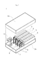
- FIG. 1 is a diagram illustrating a battery pack according to the present invention, and is an exploded perspective view with a part of a housing removed.
- the battery pack 1 of the present invention accommodates a plurality of battery modules 5 and a protection circuit board 7 in a casing made up of a first casing piece 3a and a second lid piece 3b.
- a battery module output line 9 connected to each battery module 5 and a unit battery voltage detection line 11 are connected to the protection circuit board 7.
- an input / output unit 13 that is electrically connected to the battery pack 1 is connected to the protection circuit board 7.
- four battery modules 5 are accommodated. Since the four battery modules 5 are connected to each other, four series, one parallel, two series, two parallels, one series, four parallels, etc. can be connected. It becomes possible to provide a battery pack.
- each unit battery constituting the battery module is connected. Individual monitoring of the operating state is possible, and overcharge, overdischarge, overcurrent, temperature abnormality, etc. can be prevented.
- the protection circuit board 7 is provided in the battery pack, it is not necessary to provide the protection circuit board 7 in each unit battery or each battery module 5.
- the same protection circuit board 7 as the same battery module 5 can be used in various ways. It becomes possible to provide a battery pack of output voltage and output current.
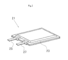
- FIG. 2 is a perspective view illustrating an example of a unit battery of a lithium ion secondary battery provided in the battery module housed in the battery pack of the present invention.
- a unit battery 21 of a lithium ion secondary battery is sealed with a film-like packaging material 23, and a positive electrode tab 25 connected to a positive electrode of a battery element and a negative electrode tab 27 connected to a negative electrode are respectively formed into a film. It is taken out from the sealing part of the exterior material 23 to the outside.
- a film-like exterior material a heat-sealable polyethylene film is arranged on the inner surface of the unit battery, a polyethylene terephthalate having a high strength, a polyamide film, etc. are arranged on the outer surface, and an aluminum foil is arranged inside and laminated. It is preferable to use a flexible laminated film.
- the positive electrode can be produced by applying a slurry in which particles of a lithium transition metal composite oxide are dispersed with a carbonaceous conductivity imparting material such as carbon black together with a binder onto an aluminum foil current collector.
- a lithium transition metal composite oxide a lithium manganese composite oxide can be used.
- the lithium manganese composite oxide may be not only an oxide containing only lithium and manganese but also a composite oxide containing other elements.
- a negative electrode can be manufactured by apply
- Unit batteries having various electric capacities can be used in the battery pack of the present invention, and examples include those having an electric capacity of 1 Ah or more and 500 Ah or less.
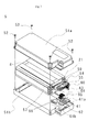
- FIG. 3 is an exploded perspective view illustrating one embodiment of the battery module housed in the battery pack of the present invention.
- the battery module 5 includes a battery pack 4 including a plurality of unit batteries 21 in battery module housings 51a and 51b.
- the battery module casings 51a and 51b can be made of a synthetic resin such as polycarbonate or ABS resin, or a metal material such as aluminum, mild steel, or stainless steel.
- the battery module housings 51 a and 51 b are coupled to each other by screws 52.
- a synthetic resin material is used as a member constituting the casing, it is possible to prevent a short circuit when a portion to which a voltage is applied comes into contact with the casing.
- the battery module 5 shown in this example forms an assembled battery 4 by connecting seven unit batteries 21 in series.
- the shape, number of connections, and electrical connection method of the unit batteries can be changed as appropriate according to the purpose of use.
- the battery module 5 is provided with a positive input / output line 54 of the assembled battery 4, a negative input / output line 55 of the assembled battery, and a battery voltage detection line 60 drawn to monitor the voltage of each unit battery. ing.
- the positive input / output line 54 is provided with a current fuse 57 for short circuit protection, and the battery voltage detection line 60 is connected with a chip fuse 61 for preventing a short circuit of the voltage detection line.
- the housing is provided with an input / output line external connection connector 59 and a battery voltage detection line external connection connector 66, and a protective circuit board is not attached.
- the chip fuse 61 for voltage detection lines has a plurality of electrically independent fuses 62 corresponding to the number of voltage detection lines on an insulating substrate. Since the voltage detection line chip fuse 61 has connectors 61a and 61b to which a plurality of circuits can be connected simultaneously, one connector 61a has a plurality of electrical contacts connected to the battery voltage detection line 60. The connector 63 is connected, and the battery voltage detection line output side connector 66 is connected by connecting the output side battery voltage detection line 65 connected to the battery voltage detection line external connection connector 64 to the other connector 61b. This makes it possible to connect all the battery voltage detection lines simultaneously.
- the current fuse 57 for protection when the positive input / output line 54 is short-circuited varies depending on the battery or the battery-utilizing device. In order to ensure safety, it is preferable to use the one having
- the positive-side input / output line 54 and the negative-side input / output line 55 connect the assembled battery 53 and the input / output line external connector 59, so that the wire material applied thereto is also appropriately selected depending on the required current amount.
- AWG # 14 (diameter 1.628 mm) or more is preferable.
- the battery voltage detection line 55 preferably has a thickness equal to or larger than AWG # 30 (diameter 0.2546 mm).
- FIG. 4 is a diagram for explaining the connection of the battery voltage detection line described in FIG. 3 in more detail
- FIG. 4A is a perspective view for explaining a connection portion with the chip fuse
- FIG. 4B is a diagram of the chip fuse
- FIG. 4C is a side view for explaining the mounting state
- FIG. 4C is a plan view of the chip fuse.
- the chip fuse 61 includes a plurality of electrically independent fuses 62, and includes connectors 61 a and 61 b that can simultaneously form electrical connections to the plurality of fuses 62.
- a connector 63 provided with a plurality of electrical contacts coupled to the battery voltage detection line 60 is connected to one connector 61a, and a connector 65 connected to the output battery voltage detection line 64 is connected to the other connector 61b.
- a plurality of battery voltage detection lines can be connected.
- the battery voltage detection line output side connector 66 is provided in the output side battery voltage detection line 64, and a battery voltage can be supplied to the protection circuit provided in the battery pack side.
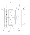
- FIG. 5 is a diagram for explaining one embodiment of the electrical wiring of the battery module of the present invention.
- the assembled battery 4 is configured by connecting seven unit batteries 21 in series.
- a positive-side input / output line 54 drawn from the positive electrode of the unit battery located at one end of the stack of the assembled battery 4, and a negative-side input / output drawn from the negative electrode of the unit battery located at the other end of the laminated body of the assembled battery
- the line 55 is connected, and the positive-side input / output line 54 is connected to the input / output line external connector 59 via the current fuse 57 and is connected to the battery protection board.
- a battery voltage detection line 60 is connected to each positive electrode side of the unit battery, and is connected to seven fuses 62 provided in the chip fuse 61 that are electrically independent from each other.
- the output side battery voltage detection line 64 on the output side of the chip fuse 61 is connected to the battery voltage detection line external connection connector 66, and is connected to the battery protection circuit via the connector.
- this battery module does not have a protection circuit for protecting the charging / discharging of the battery on the battery module side, a plurality of battery modules can be freely connected in series, in parallel, or in accordance with the required voltage and current, or Series-parallel connection is possible.
- the number of batteries in the assembled battery can be appropriately set according to the voltage and current required by the battery-using device. As typical voltages for battery-operated devices, there are 12V and 24V systems, but in the case of lithium ion secondary batteries, 3 to 4 batteries are connected in series in the 12V system, It is preferable to connect 6-8 pieces in series. Further, by changing the number of series connections, it is possible to cope with various voltages including 36V, 42V and the like.
- Example 1 The positive electrode of the lithium ion secondary battery was produced as follows. A positive electrode active material layer obtained by mixing, dispersing and stirring lithium manganese composite oxide powder, carbonaceous conductivity imparting material, and polyvinylidene fluoride in N-methyl-2-pyrrolidone (NMP) at a mass ratio of 90: 5: 5 A slurry was prepared. Next, this slurry was uniformly applied to both surfaces of an aluminum foil having a thickness of 20 ⁇ m using a doctor blade to produce a positive electrode.
- NMP N-methyl-2-pyrrolidone
- the negative electrode was prepared by mixing and stirring amorphous carbon powder and polyvinylidene fluoride in N-methyl-2-pyrrolidone (NMP) at a mass ratio of 91: 9 to prepare a slurry of the negative electrode active material layer. Next, this slurry was applied to both surfaces of a 10 ⁇ m thick copper foil using a doctor blade to produce a negative electrode.
- NMP N-methyl-2-pyrrolidone
- a positive electrode plate and a negative electrode plate coated on both sides with a positive electrode active material layer and a negative electrode active material layer are impregnated with an electrolytic solution in a battery element laminated via a separator, and sealed with a film-like exterior material to be a lithium ion secondary battery
- a unit cell was prepared. The capacity of the unit battery was 4.0 Ah.
- a chip comprising seven of these secondary batteries connected in series to form an assembled battery, housed in a battery module housing, and a battery voltage detection line attached to each unit battery having seven electrically independent fuses
- the connector was connected to the connector at one end of the fuse, and the other end of the chip fuse was connected to the connector for external connection.
- the positive input / output line was connected to one end of the current fuse, and the other end of the current fuse and the negative input / output line were connected to an external connection connector.
- the battery pack can be manufactured by storing a desired number of the battery modules manufactured in this way in the battery pack and connecting it to the protective circuit board.
- a battery pack to which a protective circuit board containing an assembled battery in which seven unit batteries are connected in series is attached, and has a size of width 90 mm ⁇ length 210 mm ⁇ thickness 70 mm. When four of these were combined, the volume was 5292 cm 3 .
- the battery pack produced in the example accommodates four battery modules that do not have a protection circuit board, and is 200 mm wide ⁇ 250 mm long ⁇ 100 mm thick, and has a volume of It was 5000 cm 3 .
- the protection circuit board reduces the volume of the battery pack by providing only one battery pack containing four battery modules. Therefore, the volume energy density can be improved.
- the battery pack of the present invention is manufactured by connecting the connectors of the required number of battery modules to the protection circuit board provided in the battery pack after the battery modules are manufactured, the assembly man-hour is reduced. Therefore, the productivity of the battery pack is improved.
- a battery module connected in two series, two in parallel, or the like can be used as the battery module.
- battery packs having different output voltages and output currents can be manufactured, and the degree of freedom in manufacturing battery packs can be increased.
- the battery pack of the present invention can be applied to secondary batteries using various active materials.
- FIG. 7 is a diagram for explaining an example of a conventional battery pack, which is a battery pack 1 in which a unit battery is a 7-series 2-parallel assembled battery and a protection circuit board is attached.
- Two battery packs 53 in which seven unit batteries are connected in series are connected in parallel in a housing formed of the lid piece 3b. Further, the protective circuit board 7 is disposed in contact with the assembled battery.
- the size of the battery pack 1 was 180 mm wide ⁇ 210 mm long ⁇ 70 mm thick. When four of the battery packs were connected, the total volume was 10484 cm 3 .
- a battery pack containing four battery modules made up of 7 series and 2 parallel assembled batteries with the same number of unit batteries as the above battery pack is 380 mm wide ⁇ 250 mm long ⁇ 100 mm thick.
- the volume was 9500 cm 3 .
- the battery pack according to the present invention can provide a battery pack having a smaller volume than the battery pack having the same output voltage and output current, each using the same number of unit batteries and provided with a protection circuit board in each battery pack. Therefore, it is possible to provide a battery pack having a large electric capacity per volume.
- each battery module made up of a combination of unit batteries of a secondary battery having a relatively large capacity, such as a lithium ion battery, has a battery Since the battery pack is provided with the protection circuit board only in the battery pack without providing the charge / discharge protection circuit board, a battery pack with high volumetric efficiency can be provided.
Landscapes
- Engineering & Computer Science (AREA)
- Power Engineering (AREA)
- Microelectronics & Electronic Packaging (AREA)
- Manufacturing & Machinery (AREA)
- Chemical & Material Sciences (AREA)
- Chemical Kinetics & Catalysis (AREA)
- Electrochemistry (AREA)
- General Chemical & Material Sciences (AREA)
- Battery Mounting, Suspending (AREA)
- Connection Of Batteries Or Terminals (AREA)
Abstract
単位電池の複数個を容器に収容した電池モジュールの複数個と、複数個の電池モジュールの充電放電を一括して制御する保護回路基板を有する直列接続や並列接続の自由度が高く、組立生産性が高く、エネルギー密度に優れた電池パック。
Description
本発明は、二次電池による多直列多並列接続に適した電池モジュールで構成される電池パックに関するものである。
近年の電子機器、特に携帯電話、ノート型パーソナルコンピュータ、ビデオカメラなどの携帯用情報機器の発達や普及に伴い、小型、軽量で、かつエネルギー密度が高い二次電池の需要が大きく伸びており、さらなる高性能化の検討がなされている。このような二次電池として特にリチウムイオン二次電池が注目されている。
リチウムイオン二次電池は、リチウムコバルト複合酸化物などの正極活物質粉末、導電性粉末、及びバインダからなる正極活物質層をアルミニウム箔からなる正極集電体表面に形成してなる正極と、炭素系の負極活物質粉末、及びバインダからなる負極活物質層を銅箔からなる負極集電体表面に形成してなる負極を、多孔質の合成樹脂フィルムからなるセパレータを介して重ね、電解液を含浸し電池要素としたものである。
電気自動車等をはじめとする動力源として電池を用いるの場合には、必要とする電気容量に応じて多数の単位電池を直列、並列に接続することが必要である。
図6は、従来の電池パックの一例を説明する図である。
図6で示す電池パックは、単位電池7個で構成される大容量リチウムイオン電池パックである。電池パック1は、第一筐体片3aと第二蓋体片3b内に、4.0Ah程度の容量を持つ単位電池を7直列1並列に配置した組電池4に、保護回路基板7が取り付けられており、外部との接続コネクタ8が備えられている。
図6は、従来の電池パックの一例を説明する図である。
図6で示す電池パックは、単位電池7個で構成される大容量リチウムイオン電池パックである。電池パック1は、第一筐体片3aと第二蓋体片3b内に、4.0Ah程度の容量を持つ単位電池を7直列1並列に配置した組電池4に、保護回路基板7が取り付けられており、外部との接続コネクタ8が備えられている。
また、図7は、従来の電池パックの他の例を説明する図である。図7で示す電池パックは、従来の単位電池14個で構成される大容量リチウムイオン電池パックである。
この電池パックでは、第一筐体片3aと第二筐体片3b内に、1.0Ah程度の容量を持つ単位電池を7直列1並列に配置した組電池4a、4bを並列に接続して7直列2並列に配置し、保護回路基板7を取り付けたうえで、外部との接続コネクタ8が備えられている。
このような電池パックでは、それぞれの電池パックには、電池の充放電時の異常事態から電池を保護する保護回路基板が取り付けられているので、保護回路基板の占める体積によって体積エネルギー密度が低下する。例えば、特許文献1参照。
この電池パックでは、第一筐体片3aと第二筐体片3b内に、1.0Ah程度の容量を持つ単位電池を7直列1並列に配置した組電池4a、4bを並列に接続して7直列2並列に配置し、保護回路基板7を取り付けたうえで、外部との接続コネクタ8が備えられている。
このような電池パックでは、それぞれの電池パックには、電池の充放電時の異常事態から電池を保護する保護回路基板が取り付けられているので、保護回路基板の占める体積によって体積エネルギー密度が低下する。例えば、特許文献1参照。
また、単位電池を直列、並列、直並列に接続した電池パックの製造は、単位電池の個数が多くなると、その製造、保守は複雑なものとなる。
そこで、単位電池を直接電池パック内に配置したものに代えて、筐体内部に複数個の単位電池を収納した電池モジュールの複数個を設けた電池パックが知られている。
電池モジュールを使用した場合には、種々の電池モジュールの組み合わせによって、様々な電気出力の電池パックの組立を効率的に行うことができる。
電池モジュールにも、電池パックと同様に、単位電池を直列、並列あるいは直並列に接続した組電池には保護回路基板が設けられている。例えば、特許文献2参照。
そこで、単位電池を直接電池パック内に配置したものに代えて、筐体内部に複数個の単位電池を収納した電池モジュールの複数個を設けた電池パックが知られている。
電池モジュールを使用した場合には、種々の電池モジュールの組み合わせによって、様々な電気出力の電池パックの組立を効率的に行うことができる。
電池モジュールにも、電池パックと同様に、単位電池を直列、並列あるいは直並列に接続した組電池には保護回路基板が設けられている。例えば、特許文献2参照。
保護回路基板には、一般に各種の半導体素子が使用されており、電池モジュールに応じた耐電圧、耐電流の半導体素子が使用されている。
例えば、出力24Vの電池モジュールにおいて、その電圧に耐えられる様に、出力電圧の2倍の48V耐電圧の素子にて保護回路を構成した場合、このモジュールを2個直列に接続した場合には、耐電圧の余裕がなくなり、3個直列に接続した場合はその時点で耐電圧を超えてしまい、異常時に半導体素子が破壊され保護機能が働かなくなるおそれがある。このため、電池モジュール同士での電気的接続には制限があった。
耐電圧の高い部品で保護回路基板を構成する方法もあるが、部品の外形寸法が大きなものとなったり、単価が高くなる等の問題があって、体積的にも価格的にも不利である。
例えば、出力24Vの電池モジュールにおいて、その電圧に耐えられる様に、出力電圧の2倍の48V耐電圧の素子にて保護回路を構成した場合、このモジュールを2個直列に接続した場合には、耐電圧の余裕がなくなり、3個直列に接続した場合はその時点で耐電圧を超えてしまい、異常時に半導体素子が破壊され保護機能が働かなくなるおそれがある。このため、電池モジュール同士での電気的接続には制限があった。
耐電圧の高い部品で保護回路基板を構成する方法もあるが、部品の外形寸法が大きなものとなったり、単価が高くなる等の問題があって、体積的にも価格的にも不利である。
本発明は、単位電池の複数個からなる組電池を収納した電池モジュールの複数個を直列、並列、あるいは直並列に接続した電池パックにおいて、共通の電池モジュールを使用した直列接続や並列接続の自由度が高く、組立生産性が高く、信頼性が大きな電池パックを提供することを課題とするものである。
本発明は、単位電池の複数個を筐体に収容した電池モジュールの複数個と、複数個の電池モジュールの充電放電を一括して制御する保護回路基板を有する電池パックである。
また、電池モジュール内の正極側入出力線あるいは負極側入出力線の少なくともいずれか一方には電流フューズが配置されている前記の電池パックである。
電池モジュール内の各単位電池の正極側または負極側のいずれか一方には、電池電圧検出線が接続されて、前記電池電圧検出線が電池モジュールからとりだされて前記保護回路基板に接続された前記の電池パックである。
また、前記電池電圧検出線は、絶縁板上に電気的に独立した複数個のフューズを形成したチップフューズに接続されて電池モジュールからとりだされている前記の電池パックである。
前記単位電池のそれぞれがフィルム状外装材によって被覆されたものである前記の電池パックである。
各単位電池の正極活物質が,リチウムマンガン複合酸化物を含む前記の電池パックである。
また、電池モジュール内の正極側入出力線あるいは負極側入出力線の少なくともいずれか一方には電流フューズが配置されている前記の電池パックである。
電池モジュール内の各単位電池の正極側または負極側のいずれか一方には、電池電圧検出線が接続されて、前記電池電圧検出線が電池モジュールからとりだされて前記保護回路基板に接続された前記の電池パックである。
また、前記電池電圧検出線は、絶縁板上に電気的に独立した複数個のフューズを形成したチップフューズに接続されて電池モジュールからとりだされている前記の電池パックである。
前記単位電池のそれぞれがフィルム状外装材によって被覆されたものである前記の電池パックである。
各単位電池の正極活物質が,リチウムマンガン複合酸化物を含む前記の電池パックである。
また、本発明の電池パックは、前記電池モジュールが合成樹脂製筐体、あるいは金属製筐体に収容されている前記の電池パックである。
本発明によれば、多様な直列接続、並列接続による出力電圧、出力電流の設定の自由度が大きく、組立の生産性が高く、容積エネルギー密度が大きな電池パックを提供することが可能となる。
次に、本発明の実施の形態について図面を参照して詳細に説明する。
図1は、本発明の電池パックを説明する図であり、筐体の一部を取り外した分解斜視図である。
本発明の電池パック1は、第一筐体片3aと第二蓋体片3bからなる筐体内に複数個の電池モジュール5、および保護回路基板7を収容している。
各電池モジュール5に接続された電池モジュール出力線9と、単位電池電圧検出線11が、保護回路基板7に接続されている。また、保護回路基板7には、電池パック1との電気的接続を行う入出力部13が接続されている。
この例で示した電池パック1では、4個の電池モジュール5を収容している。4個の電池モジュール5の相互の接続によって、4直列1並列、2直列2並列、1直列4並列等の接続が可能であるので、同一の構成の電池モジュールによって、種々の出力電圧、出力電流の電池パックを提供することが可能となる。
図1は、本発明の電池パックを説明する図であり、筐体の一部を取り外した分解斜視図である。
本発明の電池パック1は、第一筐体片3aと第二蓋体片3bからなる筐体内に複数個の電池モジュール5、および保護回路基板7を収容している。
各電池モジュール5に接続された電池モジュール出力線9と、単位電池電圧検出線11が、保護回路基板7に接続されている。また、保護回路基板7には、電池パック1との電気的接続を行う入出力部13が接続されている。
この例で示した電池パック1では、4個の電池モジュール5を収容している。4個の電池モジュール5の相互の接続によって、4直列1並列、2直列2並列、1直列4並列等の接続が可能であるので、同一の構成の電池モジュールによって、種々の出力電圧、出力電流の電池パックを提供することが可能となる。
また、本発明の電池パック1の保護回路基板7には、各電池モジュール5に接続した電池モジュール出力線9および単位電池電圧検出線11が接続されているので電池モジュールを構成する各単位電池の動作状態の個別の監視が可能であり、過充電、過放電、過電流、温度異常等の防止が可能となる。
このように電池パックに保護回路基板7を設けているので、各単位電池あるいは各電池モジュール5のそれぞれに保護回路基板7を設ける必要がない。
また、保護回路基板7に、電池モジュールを任意の直列、並列あるいは直並列接続が選択可能な回路を形成することによって、同一の電池モジュール5と同一の保護回路基板7を用いることで、多様な出力電圧,出力電流の電池パックを提供することが可能となる。
このように電池パックに保護回路基板7を設けているので、各単位電池あるいは各電池モジュール5のそれぞれに保護回路基板7を設ける必要がない。
また、保護回路基板7に、電池モジュールを任意の直列、並列あるいは直並列接続が選択可能な回路を形成することによって、同一の電池モジュール5と同一の保護回路基板7を用いることで、多様な出力電圧,出力電流の電池パックを提供することが可能となる。
図2は、本発明の電池パックに収容する電池モジュール内に設けるリチウムイオン二次電池の単位電池の一例を説明する図であり、斜視図である。
リチウムイオン二次電池の単位電池21は、フィルム状外装材23によって封口されたものであって、電池要素の正極に接続された正極タブ25と負極に接続された負極タブ27を、それぞれフィルム状外装材23の封口部より外部へ取り出されている。
フィルム状外装材としては、単位電池の内面に熱融着性のポリエチレンフィルムを配置し、外面には、強度が大きなポリエチレンテレフタレート、ポリアミドフィルム等を配置し、内部にアルミニウム箔を配置して積層した可撓性の積層フィルムを用いることが好ましい。
リチウムイオン二次電池の単位電池21は、フィルム状外装材23によって封口されたものであって、電池要素の正極に接続された正極タブ25と負極に接続された負極タブ27を、それぞれフィルム状外装材23の封口部より外部へ取り出されている。
フィルム状外装材としては、単位電池の内面に熱融着性のポリエチレンフィルムを配置し、外面には、強度が大きなポリエチレンテレフタレート、ポリアミドフィルム等を配置し、内部にアルミニウム箔を配置して積層した可撓性の積層フィルムを用いることが好ましい。
また、正極は、リチウム遷移金属複合酸化物の粒子をカーボンブラック等の炭素質導電性付与材を結着剤とともに分散したスラリーをアルミニウム箔からなる集電体上に塗布して作製することができる。
リチウム遷移金属複合酸化物としては、リチウムマンガン複合酸化物を用いることができる。リチウムマンガン複合酸化物を用いた場合には、リチウムコバルト複合酸化物を使用した電池に比べて充電時の安全性が高いので個々の単位電池の保護回路を簡単なものとすることができる。したがって、電池モジュールを小型化することが可能となる。
リチウムマンガン複合酸化物は、リチウムとマンガンのみを含有する酸化物のみではなく、他の元素を含む複合酸化物であっても良い。
リチウム遷移金属複合酸化物としては、リチウムマンガン複合酸化物を用いることができる。リチウムマンガン複合酸化物を用いた場合には、リチウムコバルト複合酸化物を使用した電池に比べて充電時の安全性が高いので個々の単位電池の保護回路を簡単なものとすることができる。したがって、電池モジュールを小型化することが可能となる。
リチウムマンガン複合酸化物は、リチウムとマンガンのみを含有する酸化物のみではなく、他の元素を含む複合酸化物であっても良い。
また、負極は、リチウムをドープ、アンドープする、黒鉛、無定形炭素粉末,ケイ素等結着剤と共に撹拌して得られるスラリーを銅箔上に塗布することによって製造することができる。
本発明の電池パックにおいて様々な電気容量の単位電池を用いることが可能であるが、電気容量が1Ah以上、500Ah以下のものを挙げることが可能である。
本発明の電池パックにおいて様々な電気容量の単位電池を用いることが可能であるが、電気容量が1Ah以上、500Ah以下のものを挙げることが可能である。
図3は、本発明の電池パックに収容する電池モジュールの一実施態様を説明する図であり、分解斜視図である。
電池モジュール5は、電池モジュール筐体51a、51b内に複数の単位電池21からなる組電池4を有している。電池モジュール筐体51a、51bは、ポリカーボネート、ABS樹脂等の合成樹脂、アルミニウム、軟鋼、ステンレス鋼等の金属材料を用いることができる。電池モジュール筐体51a、51bはビス52によって相互に結合されている。
筐体を構成する部材として合成樹脂材料を用いた場合には、電圧を印加した部分が筐体と接触した場合に短絡を防止することが可能である。一方、放熱特性と筐体の強度が必要な場合には金属材料を用いることが好ましい。
この例で示した電池モジュール5は、7個の単位電池21を直列に接続して組電池4を形成している。単位電池の形状、接続個数、電気的接続方法は使用目的に応じて適宜変更することが可能である。
電池モジュール5は、電池モジュール筐体51a、51b内に複数の単位電池21からなる組電池4を有している。電池モジュール筐体51a、51bは、ポリカーボネート、ABS樹脂等の合成樹脂、アルミニウム、軟鋼、ステンレス鋼等の金属材料を用いることができる。電池モジュール筐体51a、51bはビス52によって相互に結合されている。
筐体を構成する部材として合成樹脂材料を用いた場合には、電圧を印加した部分が筐体と接触した場合に短絡を防止することが可能である。一方、放熱特性と筐体の強度が必要な場合には金属材料を用いることが好ましい。
この例で示した電池モジュール5は、7個の単位電池21を直列に接続して組電池4を形成している。単位電池の形状、接続個数、電気的接続方法は使用目的に応じて適宜変更することが可能である。
本電池モジュールは5、前記組電池4の正極側入出力線54、前記組電池の負極側入出力線55、各単位電池の電圧を監視するために引き出された電池電圧検出線60が設けられている。
正極側入出力線54には、短絡時保護用の電流ヒューズ57が設けられており、電池電圧検出線60には電圧検出線の短絡防止用のチップフューズ61が接続されている。
また、筐体には、入出力線外部接続コネクタ59および電池電圧検出線外部接続コネクタ66が設けられており、保護回路基板は取り付けられていない。
正極側入出力線54には、短絡時保護用の電流ヒューズ57が設けられており、電池電圧検出線60には電圧検出線の短絡防止用のチップフューズ61が接続されている。
また、筐体には、入出力線外部接続コネクタ59および電池電圧検出線外部接続コネクタ66が設けられており、保護回路基板は取り付けられていない。
図3で示した例では、電圧検出線用のチップフューズ61は、絶縁性基板上に電圧検出線の数に応じた電気的に独立した複数個のフューズ62を有している。
電圧検出線用チップフューズ61は、複数個の回路を同時に接続可能なコネクタ61aおよび61bを有しているので、一方のコネクタ61aに電池電圧検出線60に結線した複数個の電気的接点を有するコネクタ63を接続し、他方のコネクタ61bに、電池電圧検出線外部接続コネクタ64に結線した出力側電池電圧検出線65を接続することにって、電池電圧検出線出力側コネクタ66と接続することによってすべての電池電圧検出線の接続を同時に行うことが可能となる。
電圧検出線用チップフューズ61は、複数個の回路を同時に接続可能なコネクタ61aおよび61bを有しているので、一方のコネクタ61aに電池電圧検出線60に結線した複数個の電気的接点を有するコネクタ63を接続し、他方のコネクタ61bに、電池電圧検出線外部接続コネクタ64に結線した出力側電池電圧検出線65を接続することにって、電池電圧検出線出力側コネクタ66と接続することによってすべての電池電圧検出線の接続を同時に行うことが可能となる。
正極側入出力線54の短絡時保護用の電流ヒューズ57は、電池あるいは電池利用機器によって異なるが、24V系には30A以上、駆動系に使用される大電流が必要なものでは100A以上の定格を持つものを適用するのが安全性を確保するうえで好ましい。
正極側入出力線54および負極側入出力線55は、組電池53と入出力線外部接続コネクタ59を接続しているので、これに適用される線材も必要な電流量によって適宜選択されるが、AWG#14番線(直径1.628mm)以上の太さが好ましい。また、電池電圧検出線55は、AWG#30番線(直径0.2546mm)以上の太さのが好ましい。
また、以上の電気接続は、線材以外にも、銅、アルミニウムなどの金属板からなるブスバーによって接続を行っても良い。
また、以上の電気接続は、線材以外にも、銅、アルミニウムなどの金属板からなるブスバーによって接続を行っても良い。
図4は、図3で説明した電池電圧検出線の接続をより詳細に説明する図であり、図4Aは、チップフューズとの接続部を説明する斜視図であり、図4Bは,チップフューズの取付状態を説明する側面図であり、図4Cは、チップフューズの平面図である。
チップフューズ61は、電気的に独立した複数個のフューズ62を備えており、複数個のフューズ62に対して同時に電気的接続を形成することが可能なコネクタ61aおよび61bを有している。したがって、一方のコネクタ61aに電池電圧検出線60に結合した複数個の電気的接点を設けたコネクタ63を接続し、他方のコネクタ61bには、出力側電池電圧検出線64に接続したコネクタ65を接続することによって、複数個の電池電圧検出線の結線を行うことが可能である。
また、出力側電池電圧検出線64には、電池電圧検出線出力側コネクタ66が設けられており、電池パック側に設けた保護回路に、電池電圧を供給することができる。
複数のフューズを備えたチップフューズを設けることによって、すべての電池電圧検出線の接続を同時に行うことが可能となる。また、電圧が印加された部分が露出しないコネクタを使用することによって信頼性が高い電気的接続を形成することができる。
チップフューズ61は、電気的に独立した複数個のフューズ62を備えており、複数個のフューズ62に対して同時に電気的接続を形成することが可能なコネクタ61aおよび61bを有している。したがって、一方のコネクタ61aに電池電圧検出線60に結合した複数個の電気的接点を設けたコネクタ63を接続し、他方のコネクタ61bには、出力側電池電圧検出線64に接続したコネクタ65を接続することによって、複数個の電池電圧検出線の結線を行うことが可能である。
また、出力側電池電圧検出線64には、電池電圧検出線出力側コネクタ66が設けられており、電池パック側に設けた保護回路に、電池電圧を供給することができる。
複数のフューズを備えたチップフューズを設けることによって、すべての電池電圧検出線の接続を同時に行うことが可能となる。また、電圧が印加された部分が露出しないコネクタを使用することによって信頼性が高い電気的接続を形成することができる。
図5は、本発明の電池モジュールの電気配線の一実施態様を説明する図である。
図5に示した例では、単位電池21の7個を直列に接続して組電池4を構成している。
組電池4の積層体の一端に位置する単位電池の正極から引き出された正極側入出力線54、前記組電池の積層体の他端に位置する単位電池の負極から引き出された負極側入出力線55が接続されており、正極側入出力線54は電流フューズ57を介して、入出力線外部接続コネクタ59に接続されており、電池保護基板へ接続される。
一方、単位電池のそれぞれの正極側には、電池電圧検出線60が接続されており、チップヒューズ61に設けた相互に電気的に独立した7個のヒューズ62に接続されている。
チップヒューズ61の出力側の出力側電池電圧検出線64が電池電圧検出線外部接続コネクタ66へ接続されており、コネクタを介して電池保護回路へと接続される。
図5に示した例では、単位電池21の7個を直列に接続して組電池4を構成している。
組電池4の積層体の一端に位置する単位電池の正極から引き出された正極側入出力線54、前記組電池の積層体の他端に位置する単位電池の負極から引き出された負極側入出力線55が接続されており、正極側入出力線54は電流フューズ57を介して、入出力線外部接続コネクタ59に接続されており、電池保護基板へ接続される。
一方、単位電池のそれぞれの正極側には、電池電圧検出線60が接続されており、チップヒューズ61に設けた相互に電気的に独立した7個のヒューズ62に接続されている。
チップヒューズ61の出力側の出力側電池電圧検出線64が電池電圧検出線外部接続コネクタ66へ接続されており、コネクタを介して電池保護回路へと接続される。
本電池モジュールは、電池モジュール側に電池の充放電の保護を行う保護回路を有していないので、必要とする電圧、電流に応じて複数個の電池モジュールを自由に直列接続、並列接続、あるいは直並列接続することが可能である。
また、組電池を構成する電池の直列個数は、電池使用機器が必要とする電圧、電流に応じて適宜設定することができる。電池使用機器の電圧として、代表的なものでは、12V系、もしくは24V系が挙げられるが、リチウムイオン二次電池の場合には、12V系では3~4個を直列に接続し、24V系では6~8個を直列に接続することが好ましい。また,直列接続個数を変えることによって、36V、42V等をはじめとした様々な電圧に対応することが可能である。
また、組電池を構成する電池の直列個数は、電池使用機器が必要とする電圧、電流に応じて適宜設定することができる。電池使用機器の電圧として、代表的なものでは、12V系、もしくは24V系が挙げられるが、リチウムイオン二次電池の場合には、12V系では3~4個を直列に接続し、24V系では6~8個を直列に接続することが好ましい。また,直列接続個数を変えることによって、36V、42V等をはじめとした様々な電圧に対応することが可能である。
以下に実施例を示して本発明を説明する。
実施例1
リチウムイオン二次電池の正極の作製は以下のようにして行った。
リチウムマンガン複合酸化物粉末、炭素質導電性付与材、およびポリフッ化ビニリデンを90:5:5の質量比でN-メチル-2-ピロリドン(NMP)に混合分散,撹拌して、正極活物質層のスラリーを調製した。次いで、このスラリーを、ドクターブレードを用いて、厚さ20μmのアルミニウム箔の両面に均一に塗布して正極を作製した
実施例1
リチウムイオン二次電池の正極の作製は以下のようにして行った。
リチウムマンガン複合酸化物粉末、炭素質導電性付与材、およびポリフッ化ビニリデンを90:5:5の質量比でN-メチル-2-ピロリドン(NMP)に混合分散,撹拌して、正極活物質層のスラリーを調製した。次いで、このスラリーを、ドクターブレードを用いて、厚さ20μmのアルミニウム箔の両面に均一に塗布して正極を作製した
また、負極は、無定形炭素粉末、ポリフッ化ビニリデンを91:9の質量比でN-メチル-2-ピロリドン(NMP)に混合分散、撹拌して負極活物質層のスラリーを調製した。次いで、このスラリーを、ドクターブレードを用いて厚さ10μmの銅箔の両面に塗布して負極を作製した。
正極活物質層、負極活物質層を両面に塗布した正極板及び負極板を、セパレータを介して積層した電池要素に電解液を含浸すると共に、フィルム状外装材によって封口してリチウムイオン二次電池の単位電池を作製した。単位電池の容量は、4.0Ahであった。
この二次電池の7個を直列接続して組電池にして、電池モジュール筐体内に収容するとともに、各単位電池に取り付けた電池電圧検出線を7個の電気的に独立したフューズを備えたチップヒューズの一端のコネクタに接続し、チップフューズの他端と外部接続用のコネクタとを接続した。
また、正極側入出力線を電流フューズの一端に接続し、電流フューズの他端と、負極側入出力線のそれぞれを、外部接続用のコネクタと接続した。
この二次電池の7個を直列接続して組電池にして、電池モジュール筐体内に収容するとともに、各単位電池に取り付けた電池電圧検出線を7個の電気的に独立したフューズを備えたチップヒューズの一端のコネクタに接続し、チップフューズの他端と外部接続用のコネクタとを接続した。
また、正極側入出力線を電流フューズの一端に接続し、電流フューズの他端と、負極側入出力線のそれぞれを、外部接続用のコネクタと接続した。
このように作製した電池モジュールの所望の個数を、電池パックに収納して、保護回路基板に接続することによって電池パックを作製することができる。
一例を挙げると、7個の単位電池を直列接続した組電池を収納した保護回路基板が取り付けられている電池パックでは、幅90mm×長さ210mm×厚さ70mmの大きさであった。これを4個合わせると、体積は5292cm3であった。
これに対して、実施例で作製した電池パックは、保護回路基板を有さない電池モジュールの4個が収容されており、幅200mm×長さ250mm×厚さ100mmの大きさであり、体積は5000cm3であった。
このように、各電池モジュールのそれぞれに保護回路基板を設けずに、保護回路基板は、4個の電池モジュールを収容した電池パックに1個のみを設けたことによって、電池パックの体積を減少させることができるので体積エネルギー密度を向上することができる。
これに対して、実施例で作製した電池パックは、保護回路基板を有さない電池モジュールの4個が収容されており、幅200mm×長さ250mm×厚さ100mmの大きさであり、体積は5000cm3であった。
このように、各電池モジュールのそれぞれに保護回路基板を設けずに、保護回路基板は、4個の電池モジュールを収容した電池パックに1個のみを設けたことによって、電池パックの体積を減少させることができるので体積エネルギー密度を向上することができる。
また、本発明の電池パックは、電池モジュールを製作した後に、必要な個数の電池モジュールのコネクタを、電池パック内に設けた保護回路基板に接続することによって製造しているので、組立工数を減ずることができるので、電池パックの生産性が向上する。
また、電池モジュールは、4個の電池のすべてを直列に接続する場合以外にも、2直列2並列などの接続をした電池モジュールを用いることができるので、同一の構成の電池モジュールを使用して、出力電圧、出力電流が異なる電池パックを製造することができ、電池パックの製造の自由度を高めることが可能となる。
また、本発明の電池パックは、各種の活物質を用いた二次電池に適用することが可能であるが、とりわけ充電時の安全性が高いリチウムマンガン複合酸化物を正極活物質としたリチウムイオン電池には好適である。また、電池パックのみに保護回路基板を使用し、電池モジュールには保護回路基板を使用しない電池パックの提供が可能となる。
実施例2
図7は、従来の電池パックの一例を説明する図であり、単位電池を7直列2並列の組電池にして保護回路基板を取り付けた電池パック1であり、第一筐体片3aと第二蓋体片3bからなる筐体内に、7個の単位電池を直列に接続した組電池53の2個を並列に接続している。また、保護回路基板7を組電池に接して配置したものである。
電池パック1の大きさは、幅180mm×長さ210mm×厚さ70mmであった。この電池パックの4個を接続した場合には合計の体積は10584cm3であった。
図7は、従来の電池パックの一例を説明する図であり、単位電池を7直列2並列の組電池にして保護回路基板を取り付けた電池パック1であり、第一筐体片3aと第二蓋体片3bからなる筐体内に、7個の単位電池を直列に接続した組電池53の2個を並列に接続している。また、保護回路基板7を組電池に接して配置したものである。
電池パック1の大きさは、幅180mm×長さ210mm×厚さ70mmであった。この電池パックの4個を接続した場合には合計の体積は10584cm3であった。
一方、上記電池パックと同様の個数の単位電池によって、7直列2並列の組電池からなる電池モジュールを4個を収納した電池パックは、幅380mm×長さ250mm×厚さ100mmの大きさであり、体積は9500cm3であった。
本発明の電池パックは、同一の個数の単位電池を使用して個々の電池パック内に保護回路基板を設けた出力電圧、出力電流が等しい電池パックに比べて体積が小さなものを提供することが可能であるので、体積当たりの電気容量が大きな電池パックを提供することが可能となる。
本発明の電池パックは、同一の個数の単位電池を使用して個々の電池パック内に保護回路基板を設けた出力電圧、出力電流が等しい電池パックに比べて体積が小さなものを提供することが可能であるので、体積当たりの電気容量が大きな電池パックを提供することが可能となる。
電池の充放電の保護回路基板を配置することが不可欠である、リチウムイオン電池等の比較的容量の大きい二次電池の単位電池を組み合わせた組電池から構成された個々の電池モジュールには電池の充放電の保護回路基板を設けずに、電池パックにのみ保護回路基板を設けた電池パックであるので、容積効率が高い電池パックを提供することができる。
Claims (6)
- 単位電池の複数個を容器に収容した電池モジュールの複数個と、複数個の電池モジュールの充電放電を一括して制御する保護回路基板を有することを特徴とする電池パック。
- 電池モジュール内の正極側入出力線あるいは負極側入出力線の少なくともいずれか一方には電流フューズが配置されていることを特徴とする請求項1記載の電池パック。
- 電池モジュール内の各単位電池の正極側または負極側のいずれか一方には、電池電圧検出線が接続されて、前記電池電圧検出線が電池モジュールからとりだされて前記保護回路基板に接続されたことを特徴とする請求項1または2記載の電池パック。
- 前記電池電圧検出線は、絶縁板上に電気的に独立した複数個のフューズを形成したチップフューズに接続されて電池モジュールからとりだされていることを特徴とする請求項3記載の電池パック。
- 前記単位電池がフィルム状外装材によって被覆されたものであることを特徴とする請求項1から4のいずれか1項に記載の電池パック。
- 前記単位電池の正極活物質が,リチウムマンガン複合酸化物であることを特徴とする請求項1から5のいずれか1項に記載の電池パック。
Priority Applications (3)
| Application Number | Priority Date | Filing Date | Title |
|---|---|---|---|
| CN2009801361485A CN102177600A (zh) | 2008-07-16 | 2009-07-15 | 电池组 |
| US13/054,432 US8487586B2 (en) | 2008-07-16 | 2009-07-15 | Battery pack |
| EP09797951.2A EP2312672B1 (en) | 2008-07-16 | 2009-07-15 | Battery pack |
Applications Claiming Priority (2)
| Application Number | Priority Date | Filing Date | Title |
|---|---|---|---|
| JP2008-184535 | 2008-07-16 | ||
| JP2008184535A JP5339407B2 (ja) | 2008-07-16 | 2008-07-16 | 電池パック |
Publications (2)
| Publication Number | Publication Date |
|---|---|
| WO2010008026A2 true WO2010008026A2 (ja) | 2010-01-21 |
| WO2010008026A3 WO2010008026A3 (ja) | 2010-03-11 |
Family
ID=41550790
Family Applications (1)
| Application Number | Title | Priority Date | Filing Date |
|---|---|---|---|
| PCT/JP2009/062829 Ceased WO2010008026A2 (ja) | 2008-07-16 | 2009-07-15 | 電池パック |
Country Status (6)
| Country | Link |
|---|---|
| US (1) | US8487586B2 (ja) |
| EP (1) | EP2312672B1 (ja) |
| JP (1) | JP5339407B2 (ja) |
| CN (1) | CN102177600A (ja) |
| TW (1) | TWI469414B (ja) |
| WO (1) | WO2010008026A2 (ja) |
Cited By (8)
| Publication number | Priority date | Publication date | Assignee | Title |
|---|---|---|---|---|
| CN102324476A (zh) * | 2011-09-08 | 2012-01-18 | 山东圣阳电源股份有限公司 | 一种动力锂离子电池组 |
| WO2012014350A1 (ja) * | 2010-07-29 | 2012-02-02 | パナソニック株式会社 | 電池モジュール |
| WO2012102115A1 (ja) * | 2011-01-28 | 2012-08-02 | 日立マクセルエナジー株式会社 | 電池ユニット |
| CN103081214A (zh) * | 2010-08-16 | 2013-05-01 | 株式会社Lg化学 | 具有紧凑结构的电池组 |
| JP2013528921A (ja) * | 2010-06-17 | 2013-07-11 | エスケー イノベーション カンパニー リミテッド | ヒューズを用いた高電圧バッテリーのセンシングラインの短絡による二次事故防止装置 |
| JP2016503228A (ja) * | 2013-05-15 | 2016-02-01 | エルジー・ケム・リミテッド | 新規な構造の電池モジュールアセンブリー |
| JP2016508659A (ja) * | 2013-05-15 | 2016-03-22 | エルジー・ケム・リミテッド | 新規な構造の電池モジュールアセンブリー |
| CN111081964A (zh) * | 2019-12-24 | 2020-04-28 | Oppo广东移动通信有限公司 | 用于终端设备的电池组件和具有其的终端设备 |
Families Citing this family (17)
| Publication number | Priority date | Publication date | Assignee | Title |
|---|---|---|---|---|
| JP6010326B2 (ja) * | 2011-06-02 | 2016-10-19 | 株式会社東芝 | 二次電池装置、二次電池装置の製造方法 |
| JP2013033687A (ja) * | 2011-08-03 | 2013-02-14 | Sharp Corp | 蓄電池モジュール |
| WO2013039298A1 (ko) * | 2011-09-16 | 2013-03-21 | 주식회사 엘지화학 | 이차전지용 부품 및 그 제조 방법, 및 상기 부품을 사용하여 제조된 이차전지와 조립 이차전지 장치 |
| DE102012204538A1 (de) | 2012-03-21 | 2013-09-26 | Robert Bosch Gmbh | Speicher für elektrische Energie sowie Aufnahmevorrichtung für mindestens einen Speicher für ein elektrisch antreibbares Fahrzeug |
| JP2013206642A (ja) * | 2012-03-28 | 2013-10-07 | Hitachi Ltd | 電池パックおよび電池システム |
| KR20140002846A (ko) * | 2012-06-26 | 2014-01-09 | 삼성에스디아이 주식회사 | 전지 모듈 및 전지 모듈의 검사 방법 |
| US20140078632A1 (en) * | 2012-09-18 | 2014-03-20 | Samsung Sdi Co., Ltd. | Battery pack, controlling method of the same, and energy storage system including the battery pack |
| WO2014045745A1 (ja) * | 2012-09-18 | 2014-03-27 | Necエナジーデバイス株式会社 | 蓄電システムおよび電池保護方法 |
| JP5835246B2 (ja) * | 2013-02-27 | 2015-12-24 | 株式会社デンソー | 電池ユニット |
| PL2899769T3 (pl) * | 2013-11-27 | 2019-09-30 | Lg Chem, Ltd. | Kieszeń od akumulatora i akumulator ją zawierający |
| CN106532148B (zh) * | 2016-11-16 | 2019-06-25 | 浙江长兴中俄新能源材料技术研究院有限公司 | 一种锂离子电池缺陷检测判断修复装置及方法 |
| TWI628909B (zh) | 2016-12-21 | 2018-07-01 | 財團法人工業技術研究院 | 具可擴充性的太陽能電池次模組 |
| US11811259B2 (en) | 2017-03-17 | 2023-11-07 | Renew Health Ltd | Power pack |
| CN111106295B (zh) * | 2018-10-25 | 2022-09-09 | 东莞新能德科技有限公司 | 电路转接板以及电池包 |
| IT201900006603A1 (it) * | 2019-05-07 | 2020-11-07 | Ats Tech Industrial Batteries S R L S | Dispositivo ausiliario per alimentazione a batteria di veicoli a trazione elettrica |
| JP7336264B2 (ja) * | 2019-05-29 | 2023-08-31 | 株式会社マキタ | バッテリパック |
| CN115189093B (zh) * | 2022-07-22 | 2023-03-07 | 阜阳隆能科技有限公司 | 快速充放电且安全的低温锂离子电池安置基座 |
Citations (2)
| Publication number | Priority date | Publication date | Assignee | Title |
|---|---|---|---|---|
| JPH11341693A (ja) | 1998-05-27 | 1999-12-10 | Denso Corp | 過充電保護回路を有する組み電池 |
| JP2006012805A (ja) | 2004-06-25 | 2006-01-12 | Samsung Sdi Co Ltd | 二次電池及び電池モジュール |
Family Cites Families (19)
| Publication number | Priority date | Publication date | Assignee | Title |
|---|---|---|---|---|
| JP3503453B2 (ja) * | 1997-12-26 | 2004-03-08 | 株式会社日立製作所 | 電池システム及びそれを用いた電気自動車 |
| US6331763B1 (en) * | 1998-04-15 | 2001-12-18 | Tyco Electronics Corporation | Devices and methods for protection of rechargeable elements |
| JP4837155B2 (ja) * | 1998-11-27 | 2011-12-14 | パナソニック株式会社 | 蓄電池 |
| JP2000223160A (ja) * | 1999-01-29 | 2000-08-11 | Sanyo Electric Co Ltd | 電源装置 |
| KR100484420B1 (ko) * | 1999-03-30 | 2005-04-22 | 마츠시타 덴끼 산교 가부시키가이샤 | 전지보호회로를 구비한 2차 전지 |
| JP4642179B2 (ja) * | 1999-10-08 | 2011-03-02 | パナソニック株式会社 | 集合型二次電池 |
| JP3968980B2 (ja) * | 2000-09-25 | 2007-08-29 | 三菱化学株式会社 | 電池パック |
| JP3609741B2 (ja) * | 2001-03-30 | 2005-01-12 | 三洋電機株式会社 | パック電池 |
| JP2002325375A (ja) | 2001-04-27 | 2002-11-08 | Sharp Corp | 二次電池パック装置 |
| JP3908076B2 (ja) * | 2002-04-16 | 2007-04-25 | 株式会社日立製作所 | 直流バックアップ電源装置 |
| JP3594023B2 (ja) * | 2002-07-30 | 2004-11-24 | 日産自動車株式会社 | 電池モジュール |
| US6850039B2 (en) * | 2003-05-02 | 2005-02-01 | O2Micro International Limited | Battery pack and a battery charging/discharging circuit incorporating the same |
| US20060257728A1 (en) * | 2003-08-08 | 2006-11-16 | Rovcal, Inc. | Separators for use in alkaline cells having high capacity |
| TWM291607U (en) * | 2005-12-09 | 2006-06-01 | Leton Technology Co Ltd | Lithium battery protector |
| US8026698B2 (en) * | 2006-02-09 | 2011-09-27 | Scheucher Karl F | Scalable intelligent power supply system and method |
| TWM294739U (en) * | 2006-02-14 | 2006-07-21 | Dynapack Internat Technology C | Improved structure of battery module |
| JP4421570B2 (ja) * | 2006-03-30 | 2010-02-24 | 株式会社東芝 | 非水電解質電池、電池パック及び自動車 |
| JP4993935B2 (ja) * | 2006-04-04 | 2012-08-08 | 三洋電機株式会社 | 組電池 |
| JP4413888B2 (ja) * | 2006-06-13 | 2010-02-10 | 株式会社東芝 | 蓄電池システム、車載電源システム、車両、および蓄電池システムの充電方法 |
-
2008
- 2008-07-16 JP JP2008184535A patent/JP5339407B2/ja active Active
-
2009
- 2009-07-15 US US13/054,432 patent/US8487586B2/en active Active
- 2009-07-15 EP EP09797951.2A patent/EP2312672B1/en active Active
- 2009-07-15 CN CN2009801361485A patent/CN102177600A/zh active Pending
- 2009-07-15 WO PCT/JP2009/062829 patent/WO2010008026A2/ja not_active Ceased
- 2009-07-16 TW TW98124054A patent/TWI469414B/zh not_active IP Right Cessation
Patent Citations (2)
| Publication number | Priority date | Publication date | Assignee | Title |
|---|---|---|---|---|
| JPH11341693A (ja) | 1998-05-27 | 1999-12-10 | Denso Corp | 過充電保護回路を有する組み電池 |
| JP2006012805A (ja) | 2004-06-25 | 2006-01-12 | Samsung Sdi Co Ltd | 二次電池及び電池モジュール |
Non-Patent Citations (1)
| Title |
|---|
| See also references of EP2312672A4 |
Cited By (19)
| Publication number | Priority date | Publication date | Assignee | Title |
|---|---|---|---|---|
| JP2013528921A (ja) * | 2010-06-17 | 2013-07-11 | エスケー イノベーション カンパニー リミテッド | ヒューズを用いた高電圧バッテリーのセンシングラインの短絡による二次事故防止装置 |
| EP2583346A4 (en) * | 2010-06-17 | 2013-12-11 | Sk Innovation Co Ltd | FUSE SECURITY COMPONENT ON A HIGH VOLTAGE BATTERY DETECTION LINE. |
| US8922959B2 (en) | 2010-06-17 | 2014-12-30 | Sk Innovation Co., Ltd. | Safety component by fuse at high voltage battery sensing line |
| CN103038917B (zh) * | 2010-07-29 | 2015-06-17 | 松下电器产业株式会社 | 电池模块 |
| WO2012014350A1 (ja) * | 2010-07-29 | 2012-02-02 | パナソニック株式会社 | 電池モジュール |
| JP4961511B2 (ja) * | 2010-07-29 | 2012-06-27 | パナソニック株式会社 | 電池モジュール |
| US9368838B2 (en) | 2010-07-29 | 2016-06-14 | Panasonic Intellectual Property Management Co., Ltd. | Battery module providing for disconnection of an abnormal cell |
| CN103038917A (zh) * | 2010-07-29 | 2013-04-10 | 松下电器产业株式会社 | 电池模块 |
| CN103081214B (zh) * | 2010-08-16 | 2015-12-09 | 株式会社Lg化学 | 具有紧凑结构的电池组 |
| CN103081214A (zh) * | 2010-08-16 | 2013-05-01 | 株式会社Lg化学 | 具有紧凑结构的电池组 |
| JP2012157217A (ja) * | 2011-01-28 | 2012-08-16 | Hitachi Maxell Energy Ltd | 電池ユニット |
| WO2012102115A1 (ja) * | 2011-01-28 | 2012-08-02 | 日立マクセルエナジー株式会社 | 電池ユニット |
| CN102324476A (zh) * | 2011-09-08 | 2012-01-18 | 山东圣阳电源股份有限公司 | 一种动力锂离子电池组 |
| JP2016503228A (ja) * | 2013-05-15 | 2016-02-01 | エルジー・ケム・リミテッド | 新規な構造の電池モジュールアセンブリー |
| JP2016508659A (ja) * | 2013-05-15 | 2016-03-22 | エルジー・ケム・リミテッド | 新規な構造の電池モジュールアセンブリー |
| US9876204B2 (en) | 2013-05-15 | 2018-01-23 | Lg Chem, Ltd. | Battery module assembly with novel structure |
| US9876203B2 (en) | 2013-05-15 | 2018-01-23 | Lg Chem, Ltd. | Battery module assembly with novel structure |
| CN111081964A (zh) * | 2019-12-24 | 2020-04-28 | Oppo广东移动通信有限公司 | 用于终端设备的电池组件和具有其的终端设备 |
| CN111081964B (zh) * | 2019-12-24 | 2022-08-09 | Oppo广东移动通信有限公司 | 用于终端设备的电池组件和具有其的终端设备 |
Also Published As
| Publication number | Publication date |
|---|---|
| WO2010008026A3 (ja) | 2010-03-11 |
| EP2312672A2 (en) | 2011-04-20 |
| US20110115437A1 (en) | 2011-05-19 |
| TWI469414B (zh) | 2015-01-11 |
| US8487586B2 (en) | 2013-07-16 |
| EP2312672A4 (en) | 2014-06-25 |
| TW201014012A (en) | 2010-04-01 |
| CN102177600A (zh) | 2011-09-07 |
| EP2312672B1 (en) | 2019-11-27 |
| JP2010027261A (ja) | 2010-02-04 |
| JP5339407B2 (ja) | 2013-11-13 |
Similar Documents
| Publication | Publication Date | Title |
|---|---|---|
| TWI469414B (zh) | Battery | |
| US20220247022A1 (en) | Battery pack | |
| CN101478034B (zh) | 保护电路板、电池包及其制造方法 | |
| US7714542B2 (en) | Compact safety device for a pouch-type secondary battery unit having many individual batteries | |
| JP5059731B2 (ja) | バッテリパック | |
| CN103066339B (zh) | 整体式单元电压感测线路熔断装置 | |
| CN110268551B (zh) | 电池模块、电池模块制造方法、电池组和车辆 | |
| CN101488595B (zh) | 二次电池模块 | |
| CN104247094A (zh) | 不规则结构的电池单元和采用该电池单元的电池模块 | |
| CN116097516A (zh) | 电池模块、包括该电池模块的电池组及其制造方法 | |
| CN114128020A (zh) | 电池模块和包括该电池模块的电池组 | |
| CN114556684A (zh) | 电池模块 | |
| US11394093B2 (en) | Secondary battery and battery module | |
| CN117751485A (zh) | 电池单体、电池及用电设备 | |
| JP7098189B2 (ja) | 二次電池及び電池モジュール | |
| JP7566029B2 (ja) | バッテリーモジュール、それを含むバッテリーパック及び自動車 | |
| JP7462764B2 (ja) | 二次電池および電池モジュール | |
| CN120359659A (zh) | 电池组及其制造方法 | |
| CN116014373A (zh) | 极耳组件、电芯、电池、电子设备 | |
| CN110121797A (zh) | 二次电池 | |
| CN110088967B (zh) | 二次电池 | |
| CN110036501B (zh) | 二次电池 | |
| JP7835900B2 (ja) | 電池モジュール | |
| JPWO2006059469A1 (ja) | フィルム外装電気デバイス集合体 | |
| US20260068031A1 (en) | Electronic device |
Legal Events
| Date | Code | Title | Description |
|---|---|---|---|
| WWE | Wipo information: entry into national phase |
Ref document number: 200980136148.5 Country of ref document: CN |
|
| 121 | Ep: the epo has been informed by wipo that ep was designated in this application |
Ref document number: 09797951 Country of ref document: EP Kind code of ref document: A2 |
|
| WWE | Wipo information: entry into national phase |
Ref document number: 2009797951 Country of ref document: EP |
|
| WWE | Wipo information: entry into national phase |
Ref document number: 13054432 Country of ref document: US |
|
| NENP | Non-entry into the national phase |
Ref country code: DE |