WO2010010850A1 - ブレードラバーの製造方法およびワイパブレード - Google Patents
ブレードラバーの製造方法およびワイパブレード Download PDFInfo
- Publication number
- WO2010010850A1 WO2010010850A1 PCT/JP2009/062959 JP2009062959W WO2010010850A1 WO 2010010850 A1 WO2010010850 A1 WO 2010010850A1 JP 2009062959 W JP2009062959 W JP 2009062959W WO 2010010850 A1 WO2010010850 A1 WO 2010010850A1
- Authority
- WO
- WIPO (PCT)
- Prior art keywords
- rubber
- blade
- monomer
- blade rubber
- lip portion
- Prior art date
- Legal status (The legal status is an assumption and is not a legal conclusion. Google has not performed a legal analysis and makes no representation as to the accuracy of the status listed.)
- Ceased
Links
Images


Classifications
-
- B—PERFORMING OPERATIONS; TRANSPORTING
- B60—VEHICLES IN GENERAL
- B60S—SERVICING, CLEANING, REPAIRING, SUPPORTING, LIFTING, OR MANOEUVRING OF VEHICLES, NOT OTHERWISE PROVIDED FOR
- B60S1/00—Cleaning of vehicles
- B60S1/02—Cleaning windscreens, windows or optical devices
- B60S1/04—Wipers or the like, e.g. scrapers
- B60S1/32—Wipers or the like, e.g. scrapers characterised by constructional features of wiper blade arms or blades
- B60S1/38—Wiper blades
- B60S1/3848—Flat-type wiper blade, i.e. without harness
- B60S1/3874—Flat-type wiper blade, i.e. without harness with a reinforcing vertebra
- B60S1/3875—Flat-type wiper blade, i.e. without harness with a reinforcing vertebra rectangular section
- B60S1/3877—Flat-type wiper blade, i.e. without harness with a reinforcing vertebra rectangular section embedded in the squeegee
-
- B—PERFORMING OPERATIONS; TRANSPORTING
- B60—VEHICLES IN GENERAL
- B60S—SERVICING, CLEANING, REPAIRING, SUPPORTING, LIFTING, OR MANOEUVRING OF VEHICLES, NOT OTHERWISE PROVIDED FOR
- B60S1/00—Cleaning of vehicles
- B60S1/02—Cleaning windscreens, windows or optical devices
- B60S1/04—Wipers or the like, e.g. scrapers
- B60S1/32—Wipers or the like, e.g. scrapers characterised by constructional features of wiper blade arms or blades
- B60S1/38—Wiper blades
- B60S1/3806—Means, or measures taken, for influencing the aerodynamic quality of the wiper blades
- B60S1/381—Spoilers mounted on the squeegee or on the vertebra
-
- B—PERFORMING OPERATIONS; TRANSPORTING
- B60—VEHICLES IN GENERAL
- B60S—SERVICING, CLEANING, REPAIRING, SUPPORTING, LIFTING, OR MANOEUVRING OF VEHICLES, NOT OTHERWISE PROVIDED FOR
- B60S1/00—Cleaning of vehicles
- B60S1/02—Cleaning windscreens, windows or optical devices
- B60S1/04—Wipers or the like, e.g. scrapers
- B60S1/32—Wipers or the like, e.g. scrapers characterised by constructional features of wiper blade arms or blades
- B60S1/38—Wiper blades
- B60S2001/3827—Wiper blades characterised by the squeegee or blade rubber or wiping element
- B60S2001/3829—Wiper blades characterised by the squeegee or blade rubber or wiping element characterised by the material of the squeegee or coating thereof
-
- B—PERFORMING OPERATIONS; TRANSPORTING
- B60—VEHICLES IN GENERAL
- B60S—SERVICING, CLEANING, REPAIRING, SUPPORTING, LIFTING, OR MANOEUVRING OF VEHICLES, NOT OTHERWISE PROVIDED FOR
- B60S1/00—Cleaning of vehicles
- B60S1/02—Cleaning windscreens, windows or optical devices
- B60S1/04—Wipers or the like, e.g. scrapers
- B60S1/32—Wipers or the like, e.g. scrapers characterised by constructional features of wiper blade arms or blades
- B60S1/38—Wiper blades
- B60S2001/3827—Wiper blades characterised by the squeegee or blade rubber or wiping element
- B60S2001/3836—Wiper blades characterised by the squeegee or blade rubber or wiping element characterised by cross-sectional shape
-
- B—PERFORMING OPERATIONS; TRANSPORTING
- B60—VEHICLES IN GENERAL
- B60S—SERVICING, CLEANING, REPAIRING, SUPPORTING, LIFTING, OR MANOEUVRING OF VEHICLES, NOT OTHERWISE PROVIDED FOR
- B60S1/00—Cleaning of vehicles
- B60S1/02—Cleaning windscreens, windows or optical devices
- B60S1/04—Wipers or the like, e.g. scrapers
- B60S1/32—Wipers or the like, e.g. scrapers characterised by constructional features of wiper blade arms or blades
- B60S1/38—Wiper blades
- B60S2001/3898—Wiper blades method for manufacturing wiper blades
-
- C—CHEMISTRY; METALLURGY
- C08—ORGANIC MACROMOLECULAR COMPOUNDS; THEIR PREPARATION OR CHEMICAL WORKING-UP; COMPOSITIONS BASED THEREON
- C08K—Use of inorganic or non-macromolecular organic substances as compounding ingredients
- C08K3/00—Use of inorganic substances as compounding ingredients
- C08K3/02—Elements
- C08K3/04—Carbon
-
- C—CHEMISTRY; METALLURGY
- C08—ORGANIC MACROMOLECULAR COMPOUNDS; THEIR PREPARATION OR CHEMICAL WORKING-UP; COMPOSITIONS BASED THEREON
- C08K—Use of inorganic or non-macromolecular organic substances as compounding ingredients
- C08K5/00—Use of organic ingredients
- C08K5/01—Hydrocarbons
-
- C—CHEMISTRY; METALLURGY
- C08—ORGANIC MACROMOLECULAR COMPOUNDS; THEIR PREPARATION OR CHEMICAL WORKING-UP; COMPOSITIONS BASED THEREON
- C08K—Use of inorganic or non-macromolecular organic substances as compounding ingredients
- C08K5/00—Use of organic ingredients
- C08K5/04—Oxygen-containing compounds
- C08K5/14—Peroxides
-
- Y—GENERAL TAGGING OF NEW TECHNOLOGICAL DEVELOPMENTS; GENERAL TAGGING OF CROSS-SECTIONAL TECHNOLOGIES SPANNING OVER SEVERAL SECTIONS OF THE IPC; TECHNICAL SUBJECTS COVERED BY FORMER USPC CROSS-REFERENCE ART COLLECTIONS [XRACs] AND DIGESTS
- Y10—TECHNICAL SUBJECTS COVERED BY FORMER USPC
- Y10T—TECHNICAL SUBJECTS COVERED BY FORMER US CLASSIFICATION
- Y10T428/00—Stock material or miscellaneous articles
- Y10T428/31504—Composite [nonstructural laminate]
- Y10T428/31855—Of addition polymer from unsaturated monomers
Definitions
- the present invention relates to a blade rubber technology provided on a wiper blade for wiping a windshield of a vehicle, and is particularly effective when applied to a blade rubber using non-diene rubber.
- Cars such as passenger cars, buses, trucks, etc. are operated by wiping off dirt, snow, insects, and muddy water splashed by vehicles traveling in front of the windshield such as windshield and rear windshield.
- a wiper blade is used to secure a person's view.
- the blade rubber provided on the wiper blade is usually formed by crosslinking natural rubber (NR) or a blend of natural rubber and chloroprene rubber (NR / CR) with sulfur.
- NR natural rubber
- NR / CR chloroprene rubber
- both NR and CR are diene rubbers, and the bond between carbon and carbon becomes unstable. Therefore, it easily reacts with ozone, oxygen, chemicals, etc. and has poor durability against weather, ozone, and chemicals (weather resistance, ozone resistance, chemical resistance).
- EPDM ethylene-propylene-diene rubber
- ethylene-propylene-diene rubber which is a non-diene rubber (preferably a polymer having a small amount of ethylene, particularly a compound which does not contain oil or uses a low pour point oil)
- EPDM does not have a double bond in the main chain, there is a problem that surface modification cannot be performed by addition reaction with chlorine, and friction can not be lowered to a necessary level as a wiper, which is practical. It was difficult to improve the wiping property to a certain level.
- Patent Documents 1 to 3 propose multi-color extrusion using EPDM for a structure including a neck and diene rubber for a lip portion for wiping glass.
- Patent Documents 4 and 5 propose a treatment using a substitution reaction with halogen for EPDM.
- JP 61-35946 A Japanese National Patent Publication No. 11-506071 Special table 2007-517085 gazette Japanese Patent Laid-Open No. 60-184551 Special table 2008-500415 JP 2008-24091 A
- Patent Documents 1 to 3 since it is multicolor extrusion molding, the manufacturing cost is higher than normal extrusion molding, and it is difficult to reflect the excellent durability of EPDM because the lip portion is not EPDM.
- Patent Documents 4 and 5 there is a problem that it is difficult to control the process because highly reactive fluorine or chlorine gas must be handled at a high temperature. In addition, there is a problem that an environmental load is caused by halogen.
- Patent Document 6 does not describe a specific effect when surface modification by irradiation treatment is performed on a non-diene rubber.
- An object of the present invention is to make it possible to manufacture a blade rubber that is excellent in both durability and wiping property by using non-diene rubber without burdening the environment.
- the blade rubber manufacturing method of the present invention is a blade rubber having a head part formed in a rectangular cross section, a lip part in contact with a surface of a windshield of a vehicle, and a neck part for coupling the head part and the lip part.
- a method of molding the blade rubber using non-diene rubber, a step of attaching a monomer to at least the lip portion of the molded blade rubber, and a portion where the monomer is attached And a step of generating a radical active site in the non-diene rubber on the surface of the part by irradiation treatment, and a step of bonding the monomer to the generated radical active site by graft polymerization.
- the blade rubber manufacturing method of the present invention is a blade rubber having a head part formed in a rectangular cross section, a lip part in contact with a surface of a windshield of a vehicle, and a neck part for coupling the head part and the lip part.
- a method of molding the blade rubber using non-diene rubber, a step of attaching a monomer to at least the lip portion of the molded blade rubber, and a portion where the monomer is attached And a step of generating a radical active site in the non-diene rubber on the surface of the portion by irradiation treatment and bonding the monomer to the generated radical active site by graft polymerization. .
- the blade rubber manufacturing method of the present invention is a blade rubber having a head part formed in a rectangular cross section, a lip part in contact with a surface of a windshield of a vehicle, and a neck part for coupling the head part and the lip part.
- the blade rubber is molded using non-diene rubber, and at least the lip portion of the blade rubber is irradiated with the non-diene on the surface of the irradiated portion.
- the blade rubber manufacturing method of the present invention is a blade rubber having a head part formed in a rectangular cross section, a lip part in contact with a surface of a windshield of a vehicle, and a neck part for coupling the head part and the lip part.
- the blade rubber manufacturing method of the present invention is a blade rubber having a head part formed in a rectangular cross section, a lip part in contact with a surface of a windshield of a vehicle, and a neck part for coupling the head part and the lip part.
- the blade rubber manufacturing method of the present invention is a blade rubber having a head part formed in a rectangular cross section, a lip part in contact with a surface of a windshield of a vehicle, and a neck part for coupling the head part and the lip part.
- a step of generating radical active sites on the non-diene rubber on the surface of the treated portion, a step of attaching a monomer to the portion where the radical active sites are generated, and graft polymerization on the generated radical active sites The step of combining the monomers with the step of separating the blade rubber intermediate by cutting at the lip portion. It is characterized in.
- the blade rubber manufacturing method of the present invention is a blade rubber having a head part formed in a rectangular cross section, a lip part in contact with a surface of a windshield of a vehicle, and a neck part for coupling the head part and the lip part.
- the wiper blade of the present invention is a wiper blade for wiping a windshield of a vehicle, and is integrally formed with a non-diene rubber, and is in contact with a head portion formed in a rectangular cross section and a surface of the windshield of the vehicle.
- a blade rubber having a lip portion, a head portion and a neck portion for connecting the lip portion, and being attached to the surface of the lip portion of the blade rubber, and being subjected to an irradiation treatment on the blade rubber It has the monomer couple
- the wiper blade of the present invention is a wiper blade for wiping a windshield of a vehicle, and is integrally formed with a non-diene rubber, and is in contact with a head portion formed in a rectangular cross section and a surface of the windshield of the vehicle.
- a blade rubber having a lip portion, a head portion and a neck portion connecting the lip portion, and attached to both side surfaces of the lip portion of the blade rubber, and the blade rubber is subjected to an irradiation treatment. And a monomer bonded to the radical active site formed on the surface of the blade rubber by graft polymerization.
- the monomer includes a vinyl group (CH 2 ⁇ CH—), an isopropenyl group (CH 2 ⁇ C (CH 3 ) —) and an allyl group (CH 2 ⁇ CHCH 2 —) in the molecule. It is a polymerizable monomer comprising a hydrophobic material having at least one of them.
- the monomers are hydroxyethyl methacrylate (2-hydroxyethyl methacrylate: HEMA), hydroxyethyl acrylate (2-hydroxyethyl acetate: HEA), glycidyl methacrylate (GMA), acrylamide, acrylamide, It is a polymerizable monomer comprising a hydrophilic monomer having at least one of acrylic acid and a metal salt thereof.
- the wiper blade of the present invention is characterized in that the non-diene rubber is composed of ethylene-propylene-diene terpolymer rubber (EPDM).
- EPDM ethylene-propylene-diene terpolymer rubber
- the wiper blade of the present invention is characterized in that the non-diene rubber is molded by peroxide crosslinking.
- the wiper blade of the present invention is characterized in that the Martens hardness on the surface of the lip portion is 5 N / mm 2 or more.
- the wiper blade of the present invention is characterized in that the monomer is not attached to the tip surface of the lip portion of the blade rubber.
- the wiper blade of the present invention is characterized in that the amount of ethylene contained in the ethylene-propylene-diene terpolymer rubber (EPDM) polymer is 62 mol% or less.
- EPDM ethylene-propylene-diene terpolymer rubber
- the wiper blade of the present invention is characterized in that the amount of ethylene contained in the ethylene-propylene-diene terpolymer rubber (EPDM) polymer is 50 mol% or more and 60 mol% or less.
- EPDM ethylene-propylene-diene terpolymer rubber
- the wiper blade of the present invention is characterized in that the tensile elastic change rate at the lip portion at an atmospheric temperature of 20 ° C. to ⁇ 20 ° C. is 170% or less.
- the wiper blade of the present invention is characterized in that the tensile elastic change rate at the lip portion at an ambient temperature of 20 ° C. to ⁇ 20 ° C. is 100% or more and 160% or less.
- the wiper blade of the present invention is characterized in that oil is added and the pour point of the oil is ⁇ 20 ° C. or lower.
- the wiper blade of the present invention is characterized in that oil is added and the pour point of the oil is ⁇ 30 ° C. or lower.
- a blade rubber is formed using a non-diene rubber, radical active sites are generated by irradiation treatment at least on the lip, and monomers are bonded by graft polymerization starting from the radical active sites. Therefore, the surface treatment can be performed to reduce the friction of the non-diene rubber having excellent durability to a practical level as a wiper.
- FIG. 2 is a cross-sectional view taken along line AA in FIG. (A)
- (b) is explanatory drawing which shows the detail of the holding
- (A)-(d) is a schematic procedure figure which shows roughly the procedure of the manufacturing method of the blade rubber of this invention. It is a schematic explanatory drawing explaining roughly the difference in a crosslinked structure.
- (A), (b) is explanatory drawing which shows the reaction form of an irradiation process, respectively.
- (A) is an enlarged view showing a state where the monomer is bonded only to the lip portion of FIG.
- FIG. 2 is a graph which shows the confirmation result of the friction reduction effect by the irradiation process of Experiment 1.
- FIG. It is a graph which shows the relationship between the light absorbency ratio of experiment 2, and micro Martens hardness. It is a graph which shows the relationship between the micro Martens hardness of Experiment 3, and a friction coefficient.
- (A), (b) is a graph which shows the temperature dependence of tensile stress. It is a photograph of the blade rubber after low temperature wiping property evaluation.
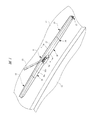
- FIG. 1 is a perspective view showing a wiper blade provided with a blade rubber according to an embodiment of the present invention.
- FIG. 2 is a cross-sectional view taken along the line AA in FIG. (B) is explanatory drawing which shows the detail of the holding
- the wiper blade 11 is attached to the tip of a wiper arm 13 of a vehicle 12.
- the wiper arm 13 swings by driving a wiper motor (not shown)
- the wiper blade 11 swings with the wiper arm 13 and windshield glass 14 ( Hereinafter, the wind glass 14 is wiped off.
- the wiper blade 11 includes a blade rubber 15 that directly contacts the wind glass 14 and a rubber holder 16 that holds the blade rubber 15.
- a pair of covers 17 are provided on both sides of the rubber holder 16 in the longitudinal direction. .
- the blade rubber 15 is formed in a rod shape having a substantially uniform cross section in the longitudinal direction, which includes a head portion 21 having a rectangular cross section, a lip portion 22, and a neck portion 23. It contacts the surface of the wind glass 14.
- the neck portion 23 is formed with a narrow width in the wiping direction with respect to the head portion 21 and the lip portion 22, whereby the lip portion 22 is coupled to the head portion 21 so as to be tiltable in the wiping direction.
- a leaf spring member 25 is mounted in each of the mounting grooves 21a.
- the plate spring member 25 is formed into a flat plate having a length similar to that of the blade rubber 15 by punching a plate material such as a steel plate, and is elastically deformable in a direction perpendicular to the wind glass 14. That is, the blade rubber 15 to which the leaf spring member 25 is attached is elastically deformable in a direction perpendicular to the window glass 14, that is, a direction in which the degree of curvature thereof is changed integrally with the leaf spring member 25. Further, in the natural state, the leaf spring member 25 is curved more strongly than the curvature of the window glass 14 in the elastically deformable direction, whereby the blade rubber 15 to which the leaf spring member 25 is attached is also bent. It is curved more strongly than the wind glass 14 in a state away from the window.
- the leaf spring member 25 is formed of a steel plate.
- the present invention is not limited to this.
- the leaf spring member 25 may be elastically deformable in a direction perpendicular to the wind glass 14 such as a hard resin. That's fine.
- the rubber holder 16 is formed in a U-shaped cross section including a top wall portion 16a extending in the longitudinal direction by a resin material and a pair of side wall portions 16b extending from both side portions of the top wall portion 16a toward the wind glass 14,
- the length of the blade rubber 15 is approximately half.
- An intermediate portion of the blade rubber 15 is disposed inside the rubber holder 16 and is covered with the rubber holder 16, and only the lip portion 22 is exposed to the outside.
- a mounting portion 26 is fixed to a substantially middle portion of one side wall portion 16 b in the longitudinal direction, and the rubber holder 16 is attached to the tip of the wiper arm 13 at the mounting portion 26.
- fins 27 are integrally formed on the top wall portion 16a, and the aerodynamic characteristics of the wiper blade 11 are improved by the fins 27.
- a holding portion 31 is provided at one end of the rubber holder 16 in the longitudinal direction (the side closer to the swing center of the wiper arm 13 when the wiper blade 11 is attached to the wiper arm 13).
- the holding part 31 includes a pair of holding claws 32 (in the figure, only one side is shown, but the other side is also provided with similar holding claws).
- These holding claws 32 are formed in the shape of a rectangular cross section protruding from the side wall portion 16b in a direction perpendicular to the longitudinal direction of the blade rubber 15 and parallel to the wiping direction, and engage with the holding grooves 24, respectively. The blade rubber 15 is held.
- the blade rubber 15 is provided with a pair of stopper portions 33a and 33b that sandwich the holding claws 32 from the longitudinal direction, and the holding claws 32 with respect to the blade rubber 15 are held in the holding grooves 24 by the stopper portions 33a and 33b. Movement in the direction along is restricted. That is, the blade rubber 15 is held by the rubber holder 16 in a state where the holding portion 31 is positioned in the longitudinal direction.
- a holding portion 34 is provided at the other end of the rubber holder 16 in the longitudinal direction.
- the holding portion 34 has a pair of holding claws each having a rectangular cross section. 35 (only one side is shown in the figure, but the other side is provided with similar holding claws). These holding claws 35 are engaged with the holding grooves 24, thereby holding the blade rubber 15. .
- the blade rubber 15 is not provided with a stopper portion at a portion where the holding claw 35 is engaged, and the holding claw 35 is movable along the holding groove 24. That is, the blade rubber 15 is held by the holding portion 34 so as to be movable in the axial direction with respect to the rubber holder 16.
- the pair of holding portions 31 and 34 are provided at both ends in the longitudinal direction of the rubber holder 16, and the blade rubber 15 is held at two points of the holding portions 31 and 34. . Therefore, when the pressing force from the wiper arm 13 is applied to the rubber holder 16 via the mounting portion 26, the pressing force is applied to the blade rubber 15 from two points at both ends of the rubber holder 16, that is, from the holding portions 31 and 34. As a result, the blade rubber 15 elastically contacts the window glass 14.
- FIGS. 4 (a) to 4 (d) are schematic procedure diagrams schematically showing the procedure of the blade rubber manufacturing method of the present invention.
- the blade rubber 15 described above includes a step of forming the blade rubber, a step of generating radical active points by irradiation treatment on the blade rubber, and a graft starting from the radical active points. It is manufactured through a step of bonding monomers by polymerization and a step of cutting the lip portion of the blade rubber in the longitudinal direction.
- non-diene rubber As the rubber used for forming the blade rubber in the step shown in FIG. 4 (a), non-diene rubber is used because of its excellent durability.
- Non-diene rubbers include, for example, ethylene-propylene-diene terpolymer rubber (EPDM), ethylene-propylene copolymer rubber (EPR), fluorine rubber (FKM), butyl rubber (IIR), silicone rubber, epichlorohydride. Rubber (CO, ECO), urethane rubber (U), acrylic rubber (ACM) and the like.
- natural rubber or a blend of natural rubber and chloroprene rubber (NR / CR) blended with a predetermined amount of non-diene rubber, or a predetermined amount of non-diene rubber blended with ester-based urethane rubber Or a mixture of a plurality of non-diene rubbers in a predetermined amount may be used.
- NR natural rubber
- NR / CR chloroprene rubber
- ethylene-propylene-diene terpolymer rubber (EPDM) and ethylene-propylene copolymer rubber (EPR) are easy to perform surface modification without the progress of decomposition reaction by irradiation treatment. ) Is preferred. Furthermore, from the viewpoint of further improving the performance of the wiper blade, ethylene-propylene-diene terpolymer rubber (EPDM) is particularly preferable because it is the lightest rubber known in the art.
- EPDM is generally classified as a rubber excellent in low temperature property, and has a low temperature property superior to that of chloroprene rubber (CR) and equivalent to that of natural rubber (NR).
- CR chloroprene rubber
- NR natural rubber
- the amount of ethylene in the polymer contained in EPDM is preferably 62 mol% or less, and more preferably 60 mol% or less.
- EPDM usually contains ethylene in an amount of 50 mol% or more.
- the tensile elastic change rate of EPDM due to a temperature change from 20 ° C. to ⁇ 20 ° C. is preferably 170% or less, and more preferably 160% or less.
- the tensile elastic change rate can be measured based on, for example, JIS K6251.
- the oil component added to EPDM those having a pour point of ⁇ 20 ° C. or lower are preferable, those having ⁇ 30 ° C. or lower are more preferable, and those having ⁇ 45 ° C. or lower are particularly preferable.
- the oil pour point can be measured based on, for example, JIS K2269. In consideration of actual profit and cost, the lower limit of the oil pour point is preferably about ⁇ 50 ° C.
- non-diene rubbers are generally known as vulcanizing agents (crosslinking agents), vulcanization accelerating aids, softeners, anti-aging agents, fillers, silane coupling agents, silica, carbon black (reinforcing agents) and the like.
- the additives can be blended and molded into a brate rubber by a conventionally known method such as press molding.
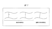
- FIG. 5 is a schematic explanatory diagram for schematically explaining the difference in the crosslinked structure.
- the sulfur bridge takes a polysulfide or monosulfide bond bridge structure in which a plurality of polymer chains or one sulfur is connected between polymer chains.
- peroxide cross-linking has a cross-linked structure in which polymer chains are directly connected by covalent bonds. That is, in a peroxide cross-linked structure in which polymer chains are directly connected by covalent bonds, the structure becomes rigid and molecular relaxation behavior is suppressed. Since the permanent deformation behavior of rubber is influenced by the relaxation phenomenon of the rubber molecular structure, the permanent deformation is suppressed by the peroxide.
- the peroxide cross-linked structure has a higher dissociation energy of the cross-linked bond than the sulfur cross-linked structure, and has a higher resistance to heat or the like than the sulfur cross-linked structure, and therefore has excellent deterioration resistance.
- the same effect as the peroxide cross-linking can be obtained by a cross-linking method having a cross-linked structure in which polymer chains are covalently bonded.
- peroxide crosslinking agents for crosslinking non-diene rubbers include 1,3-bis (tertiary butyl peroxyisopropyl) benzene, 2,5-dimethyl-2,5-di (tertiary butyl peroxy).
- These peroxide crosslinking agents may be used alone or in combination of two or more.
- Examples of the irradiation process for generating radical active sites on the blade rubber formed in the step shown in FIG. 4B include, for example, an electron beam irradiation process, an ultraviolet irradiation process, a plasma irradiation process, radiation ( ⁇ rays, ⁇ rays, ( ⁇ -ray) irradiation treatment, ion beam irradiation treatment, corona discharge irradiation treatment and the like can be mentioned, and among these, electron beam irradiation treatment is particularly preferable from the viewpoint of high treatment efficiency.
- radical active sites are generated in the blade rubber, and the graft polymerization reaction proceeds from the radical active sites as a starting point in the step shown in FIG.
- 6 (a) and 6 (b) are explanatory views showing reaction modes of irradiation treatment, respectively.
- 6A and 6B only the lip portion of the blade rubber formed so that the lip portions of the pair of blade rubbers face each other before the blade rubber is cut is illustrated.
- FIGS. 6 (a) and 6 (b) there are two methods for the irradiation treatment for promoting the graft polymerization reaction from the generated radical active point as a starting point.
- the rubber is irradiated with an electron beam or the like to generate radical active sites, and then the monomer is attached to the blade rubber surface, and the monomer is bonded by graft polymerization.
- This is a pre-irradiation treatment for generating radical active sites by treatment.
- both the irradiation treatment and the graft polymerization reaction are preferably performed in a nitrogen atmosphere.
- the absorbed dose of the pre-irradiation treatment is preferably 50 to 500 kGy in a deoxygenated state.
- the process shown in FIG. 6 (b) is a simultaneous irradiation process in which generation of radical active sites and graft polymerization are performed simultaneously.
- the simultaneous irradiation treatment for example, irradiation with an electron beam or the like for generating the above-described radical active site is performed in a state in which a monomer used for graft polymerization is attached to the surface of the blade rubber by coating or dipping.
- the absorbed dose of the simultaneous irradiation treatment is preferably 10 to 200 kGy.
- Graft polymerization can be performed by a generally known method, and any of a hydrophobic material and a hydrophilic material may be used as the polymerizable monomer used in the graft polymerization.
- the hydrophobic material has at least one of vinyl group (CH 2 ⁇ CH—), isopropenyl group (CH 2 ⁇ C (CH 3 ) —) and allyl group (CH 2 ⁇ CHCH 2 —) in the molecule.
- Examples of the polymerizable monomer include a compound having a hydrophobic structure of hydrocarbon, organosilicon, or fluorine at the molecular terminal, or a functional group that can impart hydrophobicity by a secondary reaction after graft polymerization.
- hydrophobic materials examples include ethyl methacrylate, vinyl methacrylate, styrene, cyclohexyl methacrylate, dodecyl methacrylate, ethyl acrylate, vinyl acrylate, cyclohexyl acrylate, dodecyl acrylate, trimethylsilyl methacrylate, methacrylic acid.
- Trimethoxysilylpropyl acid 3- (methacryloyloxy) propyltris (trimethylsiloxy) silane, trimethylsilyl acrylate, trimethoxysilylpropyl acrylate, 3- (acryloyloxy) propyltris (trimethylsiloxy) silane, methacrylic acid 1H, 1H , 3H-tetrafluoropropyl, 2,2,2-trifluoroethyl methacrylate, 2- (perfluorobutyl) ethyl methacrylate, acrylic acid 1H, 1H, H- tetrafluoropropyl, 2,2,2-trifluoroethyl acrylate, methacrylic acid 2- (perfluorobutyl) ethyl, and derivatives thereof.
- These hydrophobic monomers may be used alone or in combination of two or more.
- hydrophilic material examples include hydroxyethyl methacrylate (2-hydroxyethyl methacrylate: HEMA), hydroxyethyl acrylate (2-hydroxyethyl acetate: HEA), glycidyl methacrylate (GMA), acrylamide, methacrylic acid, and acrylic acid. And metal salts thereof.
- HEMA hydroxyethyl methacrylate
- HEA hydroxyethyl acrylate
- GMA glycidyl methacrylate
- acrylamide methacrylic acid
- acrylic acid and acrylic acid.
- metal salts thereof examples include hydroxyethyl methacrylate (2-hydroxyethyl methacrylate: HEMA), hydroxyethyl acrylate (2-hydroxyethyl acetate: HEA), glycidyl methacrylate (GMA), acrylamide, methacrylic acid, and acrylic acid. And metal salts thereof.
- These hydrophilic monomers may be used individually by 1
- the blade rubber described above is manufactured as a pair of blade rubber molded bodies (blade rubber intermediate bodies) formed so that the lip portions face each other.
- the pair of blade rubber molded bodies are cut in the longitudinal direction at the lip portion in the step shown in FIG. 4D to form a blade rubber.
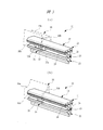
- FIG. 7A is an enlarged view showing a state in which the monomer is bonded only to the lip portion of FIG. 2
- FIG. 7B is an enlarged view showing a state in which the monomer is bonded to the entire blade rubber of FIG. is there.
- the portion where the monomer is bonded is indicated by hatching. Since the pair of rubber moldings is cut with the graft polymerized monomer attached, as shown in FIGS. 7A and 7B, the monomer adheres to the cutting surface (tip surface) 36 of the blade rubber. Not done.
- the window glass is wiped by the side surfaces 37a and 37b to which the monomer is bonded.
- the window glass is not wiped by the cut surface 36 to which no monomer is attached.
- the above-described irradiation and graft polymerization treatment for generating radical active sites such as an electron beam need not be performed on a portion of the blade rubber molded body that does not come into contact with the window glass, such as a head portion.
- the portions that are not irradiated with the electron beam or the like are masked in advance, and only the necessary portions such as the lip portion 22 of the blade rubber molded body are irradiated with the electron beam or the like as in the example shown in FIGS. 7A and 7B. May be performed.
- the blade rubber surface is modified to modify the surface of the blade rubber.
- the rubber surface friction can be reduced as well as the diene rubber surface-treated with chlorine.
- non-diene rubbers are superior in durability at both low and high temperatures, and have less reaction with heat, water, ultraviolet rays, ozone, oxygen, chemicals, etc. compared to diene rubbers.
- it could not be surface treated with chlorine.
- it has been difficult to produce a blade rubber that can be wiped off with high visibility by using only non-diene rubbers with less chatter.
- the non-diene rubber can be subjected to a surface treatment for reducing friction, a blade rubber excellent in durability and wiping property can be obtained.
- the surface treatment can be performed without using a halogen, a blade rubber can be produced without imposing a load on the environment.
- the blade rubber 15 is manufactured as a pair of blade rubber molded bodies formed such that the lip portions 22 face each other, and the blade rubber 15 is cut in the longitudinal direction at the lip portions 22.
- the present invention is not limited to this, and the blade rubber 15 may be separately formed from the beginning, and the cutting step may be omitted.
- the wiper blade 11 wipes the front window glass 14 of the vehicle 12.
- the present invention is not limited to this, and the wiper blade 11 may wipe the rear window glass of the vehicle 12. Good.
- the leaf spring member 25 is attached to the attachment groove 21a of the blade rubber 15.
- the structure is not limited to this, and the leaf spring member 25 is directly fixed to the blade rubber 15 by adhesion or the like. Also good.
- the present invention can be applied to wiper blades used in various types of wiper devices such as a tandem type and a counter wiping type.
- micro Martens hardness (N / mm 2 ) of the blade rubber molded body after the treatment was measured with a dynamic ultra micro hardness meter manufactured by Shimadzu Corporation in accordance with ISO14577-1.
- FIG. 8 shows a graph of FIG. 8 as an example in which a blade rubber molded body molded by EPDM was subjected to simultaneous irradiation treatment (example of EPDM graft) and other examples as comparative examples.
- the rubber surface does not become hard even if the blade rubber molded body molded by EPDM is subjected to normal chlorination.
- EPMA is irradiated with an electron beam and HEMA is graft polymerized
- the hardness of the fine Martens is reduced. Improved to about 4/3 of the chlorinated NR example.
- the hardness of the rubber surface can be improved to the same or higher level than when chlorination is performed on a blade rubber molded body molded by NR. It was.
- micro-Martens hardness As shown in FIG. 9, there was a tendency for the micro-Martens hardness to improve as the absorbance ratio increased. That is, it was found that the micro-Martens hardness can be increased by electron beam irradiation graft polymerization of HEMA.
- Rubber material B Rubber material using NR as a diene rubber instead of EPDM and not surface-treated Rubber material C: Sulfur vulcanized NR rubber material Rubber material D: Rubber material C was chlorinated As a result of the rubber material evaluation, the rubber materials A and B did not crack after 200 hours, but the rubber materials C to E cracked as early as 2 to 4 hours. That is, it was found that rubber materials A and B manufactured by the blade rubber manufacturing method of the present invention are extremely excellent in ozone resistance compared to rubber materials C to E manufactured by a manufacturing method different from the present invention.
- EPDM polymer 20 phr for EP24 (manufactured by JSR, the same applies to No. 3 below), 80 phr for EP27; Reinforcing agent: 40 phr Asahi # 60 (Asahi Carbon Co., Ltd.) as FEF (Fast Extrusion Furnace); Vulcanizing agent: 5 phr of park mill D-40 (manufactured by NOF Corporation) as peroxide (DCP); Vulcanization accelerating aid: 5 phr of a mixture of two types of zinc oxide (made by Sakai Chemical Industry Co., Ltd.) as zinc oxide, and 1 phr of Lunac S-20 (made by Kao Corporation) as stearic acid; Plasticizer: 10 phr of Diana Process Oil NR-26 (Idemitsu Kosan Co., Ltd.) as naphthenic oil.
- No. 2 As an EPDM polymer, No. 20 except that EP21 was replaced with 20 phr and EP107 was replaced with 80 phr. Same as 1.
- EPT3072EH manufactured by Mitsui Chemicals
- EPT3045H was replaced with 50 phr. Same as 1.
- the tensile stress change rate (%) based on JIS K2269 from ⁇ 20 ° C. to 20 ° C. was measured, and the low temperature wiping property was evaluated as follows. No. above.
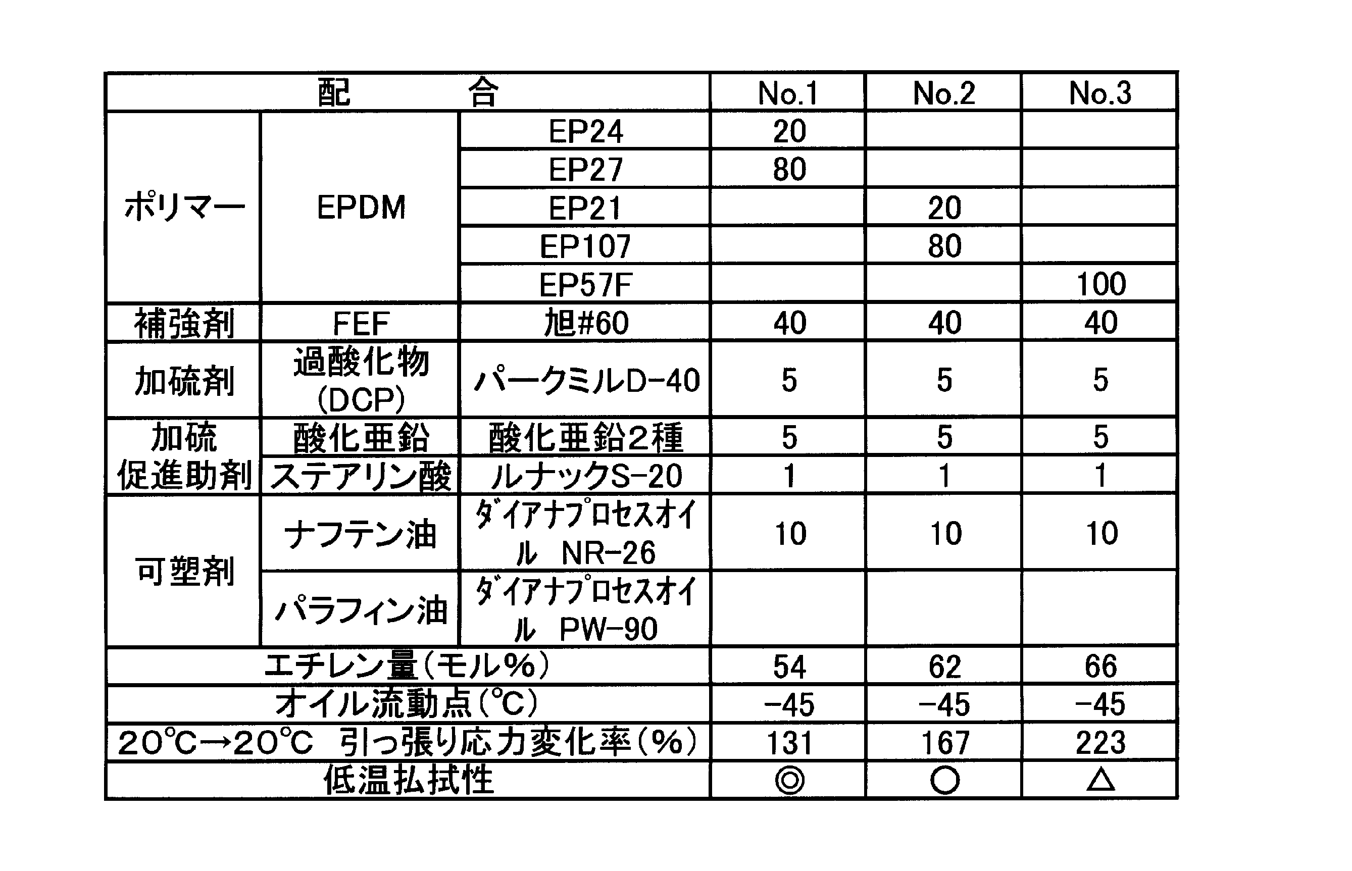
- the results are shown in Tables 2 and 3, together with the composition of 1 to 5 and the ethylene amount (mol%) of the EPDM polymer and the oil pour point (° C.) of the oil component.
- the temperature dependence of the tensile stress is shown in the graphs of FIGS. 11A and 11B, and the blade rubber after the low temperature wiping property evaluation is shown in the photograph of FIG.
- the ethylene amount and oil pour point were extracted from the product catalog.
- the oil pour point is usually measured based on JIS K6251.
- the tensile stress change rate from ⁇ 20 ° C. to 20 ° C. could be suppressed to 170% or less.
- the low temperature wiping property was good.
- no. In No. 1 it could be suppressed to 160%, and the low temperature wiping property was excellent.
- no. In No. 3 the tensile stress change rate from ⁇ 20 ° C. to 20 ° C. greatly exceeded 200%, and the low temperature wiping property was not good.
- the present invention can be used for a blade rubber provided on a wiper blade for wiping a windshield of a vehicle.
Landscapes
- Engineering & Computer Science (AREA)
- Mechanical Engineering (AREA)
- Physics & Mathematics (AREA)
- Fluid Mechanics (AREA)
- Quality & Reliability (AREA)
- Treatments Of Macromolecular Shaped Articles (AREA)
- Graft Or Block Polymers (AREA)
Abstract
Description

〔実験1〕照射処理による摩擦低減効果の確認
非ジエン系ゴムとしてのEPDM100phrに過酸化物架橋剤5phr、酸化亜鉛5phr、ステアリン酸2phr、加硫促進助剤1phr、カーボンブラック50phrを配合してプレス成形により一対のブレードラバー成形体を成形した。このブレードラバー成形体をHEMA濃度50重量%の水溶液に浸漬させ、25℃温度下で電子線10kGyの図6(b)に示した同時照射処理を行った(電子線照射によるラジカル活性点の生成とHEMAのグラフト重合とを同時に行った)。処理後のブレードラバー成形体の微小マルテンス硬さ(N/mm2)をISO14577-1に準じて島津製作所製ダイナミック超微小硬度計により測定した。
上記実験1のEPDMにより成形したブレードラバー成形体に対する同時照射処理による表面改質の進行度合いを、全反射測定法(Attenuated Total ReflectionというFT/IR分析システム:ATR-FT/IR)から得られる吸光度比(1720cm-1/1375cm-1)と、ラバー表面の微小マルテンス硬さとの関係を調べることにより確認した。結果を図9のグラフに示す。
上記実験1のEPDMにより成形したブレードラバー成形体に対する同時照射処理において、微小マルテンス硬さを種々変化させた検討基材の摩擦力測定結果から、微小マルテンス硬さと摩擦係数との相関関係を確認した。結果を図10のグラフに示す。なお、摩擦力は下記の条件で測定した。
荷重:15gf
摺動半径:70mm
回転数:173.5rpm
摩擦速度:1.3m/s
温度:25℃
湿度:70%
相手材:ガラス板
図10に示すように、微小マルテンス硬さが増大すると、摩擦係数が低下する傾向が観られた。そして、微小マルテンス硬さが5N/mm2以上となると、塩素処理したものより低摩擦となった。つまり、EPDMへのHEMAの電子線照射グラフト重合により摩擦を低減できることがわかった。
上記実験1のEPDMにより成形したブレードラバー成形体(ゴム材A)およびその他のゴム材B~Eを下記条件で保持し、クラック発生の有無を調べることで耐オゾン性を評価した。
オゾン濃度:50pphm
伸張率:40%
保持時間:クラックが発生するまで(最長200時間)
その他のゴム材としては、以下のものについて評価を行った。
ゴム材C:硫黄加硫されたNRゴム材
ゴム材D:ゴム材Cに塩素処理を行ったゴム材
評価の結果、ゴム材A、Bでは200時間経過後もクラックが発生しなかったが、ゴム材C~Eでは2時間~4時間という早期にクラックが発生した。つまり、本発明のブレードラバーの製造方法により製造したゴム材AおよびBは、本発明と異なる製造方法により製造したゴム材C~Eに比べて極めて対オゾン性に優れることがわかった。
EPDMあるいはオイル成分を異ならせた、それぞれ以下のNo.1~5の配合でブレードラバー成形体を実験1と同様にして製造した後、切断してブレードラバーを得た。
EPDMポリマー:EP24(JSR社製、以下No.3まで同じく)を20phr、EP27を80phr;
補強剤:FEF(Fast Extrusion Furnace)として旭#60(旭カーボン社製)を40phr;
加硫剤:過酸化物(DCP)としてパークミルD-40(日本油脂社製)を5phr;
加硫促進助剤:酸化亜鉛として酸化亜鉛2種(堺化学工業社製)を混合したものを5phr、ステアリン酸としてルナックS-20(花王社製)を1phr;
可塑剤:ナフテン油としてダイアナプロセスオイルNR-26(出光興産社製)を10phr。
EPDMポリマーとしてEP21を20phr、EP107を80phrに代えた以外はNo.1と同じく。
EPDMポリマーとしてEP57Fを100phrに代えた以外はNo.1と同じく。
EPDMポリマーとしてEPT3072EH(三井化学社製)を50phr、EPT3045Hを50phrに代えた以外はNo.1と同じく。
可塑剤(オイル成分)としてパラフィン油(ダイアナプロセスオイルPW-90)を10phrに代えた以外はNo.4と同じく。
それぞれのブレードラバーについて、図1に示したワイパブレードを組み立てJIS D5710に準じて-20℃にて払拭性を評価し、拭きムラが殆どないものを◎、拭きムラが少ないものを○、拭きムラが多いものを△とした。

Claims (22)
- 断面矩形に形成されたヘッド部と、車両のウインドガラスの面上に接するリップ部と、前記ヘッド部と前記リップ部を結合するネック部とを有するブレードラバーの製造方法であって、
非ジエン系ゴムを用いて前記ブレードラバーを成形する工程と、
成形された前記ブレードラバーの少なくとも前記リップ部にモノマーを付着する工程と、
前記モノマーが付着された部分に照射処理をして当該部分の表面の前記非ジエン系ゴムにラジカル活性点を生成する工程と、
生成された前記ラジカル活性点にグラフト重合により前記モノマーを結合させる工程と、
を有することを特徴とするブレードラバーの製造方法。 - 断面矩形に形成されたヘッド部と、車両のウインドガラスの面上に接するリップ部と、前記ヘッド部と前記リップ部を結合するネック部とを有するブレードラバーの製造方法であって、
非ジエン系ゴムを用いて前記ブレードラバーを成形する工程と、
成形された前記ブレードラバーの少なくとも前記リップ部にモノマーを付着する工程と、
前記モノマーが付着された部分に照射処理をして当該部分の表面の前記非ジエン系ゴムにラジカル活性点を生成するとともに、生成された前記ラジカル活性点にグラフト重合により前記モノマーを結合させる工程と、
を有することを特徴とするブレードラバーの製造方法。 - 断面矩形に形成されたヘッド部と、車両のウインドガラスの面上に接するリップ部と、前記ヘッド部と前記リップ部を結合するネック部とを有するブレードラバーの製造方法であって、
非ジエン系ゴムを用いて前記ブレードラバーを成形する工程と、
前記ブレードラバーの少なくとも前記リップ部に照射処理をして前記照射処理がされた部分の表面の前記非ジエン系ゴムにラジカル活性点を生成する工程と、
前記ラジカル活性点が生成された部分にモノマーを付着する工程と、
生成された前記ラジカル活性点にグラフト重合により前記モノマーを結合させる工程と、
を有することを特徴とするブレードラバーの製造方法。 - 断面矩形に形成されたヘッド部と、車両のウインドガラスの面上に接するリップ部と、前記ヘッド部と前記リップ部を結合するネック部とを有するブレードラバーの製造方法であって、
非ジエン系ゴムを用いて前記ブレードラバーを成形する工程と、
前記ブレードラバーの少なくとも前記リップ部に照射処理をして前記照射処理がされた部分の表面の前記非ジエン系ゴムにラジカル活性点を生成する工程と、
前記ラジカル活性点が生成された部分にモノマーを付着し、前記モノマーが付着された前記ラジカル活性点にグラフト重合により前記モノマーを結合させる工程と、
を有することを特徴とするブレードラバーの製造方法。 - 断面矩形に形成されたヘッド部と、車両のウインドガラスの面上に接するリップ部と、前記ヘッド部と前記リップ部を結合するネック部とを有するブレードラバーの製造方法であって、
非ジエン系ゴムを用いて、一対の前記リップ部が向き合うブレードラバー中間体を成形する工程と、
成形された前記ブレードラバー中間体の少なくとも前記リップ部にモノマーを付着する工程と、
前記モノマーが付着された部分に照射処理をして当該部分の表面の前記非ジエン系ゴムにラジカル活性点を生成する工程と、
生成された前記ラジカル活性点にグラフト重合により前記モノマーを結合させる工程と、
前記ブレードラバー中間体を前記リップ部で切断することによって分離する工程と、
を有することを特徴とするブレードラバーの製造方法。 - 断面矩形に形成されたヘッド部と、車両のウインドガラスの面上に接するリップ部と、前記ヘッド部と前記リップ部を結合するネック部とを有するブレードラバーの製造方法であって、
非ジエン系ゴムを用いて、一対の前記リップ部が向き合うブレードラバー中間体を成形する工程と、
成形された前記ブレードラバー中間体の少なくとも前記リップ部にモノマーを付着する工程と、
前記モノマーが付着された部分に照射処理をして当該部分の表面の前記非ジエン系ゴムに前記ラジカル活性点を生成するとともに、生成された前記ラジカル活性点にグラフト重合により前記モノマーを結合させる工程と、
前記ブレードラバー中間体を前記リップ部で切断することによって分離する工程と、
を有することを特徴とするブレードラバーの製造方法。 - 断面矩形に形成されたヘッド部と、車両のウインドガラスの面上に接するリップ部と、前記ヘッド部と前記リップ部を結合するネック部とを有するブレードラバーの製造方法であって、
非ジエン系ゴムを用いて、一対の前記リップ部が向き合うブレードラバー中間体を成形する工程と、
前記ブレードラバー中間体の少なくとも前記リップ部に照射処理をして前記照射処理がされた部分の表面の前記非ジエン系ゴムにラジカル活性点を生成する工程と、
前記ラジカル活性点が生成された部分にモノマーを付着する工程と、
生成された前記ラジカル活性点にグラフト重合により前記モノマーを結合させる工程と、
前記ブレードラバー中間体を前記リップ部で切断することによって分離する工程と、
を有することを特徴とするブレードラバーの製造方法。 - 断面矩形に形成されたヘッド部と、車両のウインドガラスの面上に接するリップ部と、前記ヘッド部と前記リップ部を結合するネック部とを有するブレードラバーの製造方法であって、
非ジエン系ゴムを用いて、一対の前記リップ部が向き合うブレードラバー中間体を成形する工程と、
前記ブレードラバー中間体の少なくとも前記リップ部に照射処理をして前記照射処理がされた部分の表面の前記非ジエン系ゴムにラジカル活性点を生成する工程と、
前記ラジカル活性点が生成された部分にモノマーを付着し、前記モノマーが付着された前記ラジカル活性点にグラフト重合により前記モノマーを結合させる工程と、
前記ブレードラバー中間体を前記リップ部で切断することによって分離する工程と、
を有することを特徴とするブレードラバーの製造方法。 - 車両のウインドガラスを払拭するワイパブレードであって、非ジエン系ゴムによって一体的に形成され、断面矩形に形成されたヘッド部と、車両のウインドガラスの面上に接するリップ部と、前記ヘッド部と前記リップ部を結合するネック部とを有するブレードラバーと、
前記ブレードラバーの前記リップ部の表面上に付着されるとともに、前記ブレードラバーに照射処理がされることによって前記ブレードラバーの表面に形成されたラジカル活性点にグラフト重合によって結合されたモノマーとを有していることを特徴とするワイパブレード。 - 車両のウインドガラスを払拭するワイパブレードであって、非ジエン系ゴムによって一体的に形成され、断面矩形に形成されたヘッド部と、車両のウインドガラスの面上に接するリップ部と、前記ヘッド部と前記リップ部を結合するネック部とを有するブレードラバーと、
前記ブレードラバーの前記リップ部の表面の両側面に付着されるとともに、前記ブレードラバーに照射処理がされることによって前記ブレードラバーの表面に形成されたラジカル活性点にグラフト重合によって結合されたモノマーとを有していることを特徴とするワイパブレード。 - 請求項9または10に記載のワイパブレードにおいて、前記モノマーが、分子中にビニル基(CH2=CH-)、イソプロペニル基(CH2=C(CH3)-)およびアリル基(CH2=CHCH2-)の少なくともいずれかを有する疎水性材料からなる重合性モノマーであることを特徴とするワイパブレード。
- 請求項9または10に記載のワイパブレードにおいて、前記モノマーが、ヒドロキシエチルメタアクリレート(2-Hydroxyethyl methacrylate:HEMA)、ヒドロキシエチルアクリレート(2-Hydroxyethyl acrylate:HEA)、グリシジルメタアクリレート(Glycidyl methacrylate:GMA)、アクリルアミド、メタクリル酸、アクリル酸およびこれらの金属塩の少なくともいずれかを有する親水性モノマーからなる重合性モノマーであることを特徴とするワイパブレード。
- 請求項9~12のいずれか1項に記載のワイパブレードにおいて、前記非ジエン系ゴムはエチレン-プロピレン-ジエン三元共重合ゴム(EPDM)からなることを特徴とするワイパブレード。
- 請求項9~13のいずれか1項に記載のワイパブレードにおいて、前記非ジエン系ゴムは過酸化物架橋によって成形されていることを特徴とするワイパブレード。
- 請求項9~14のいずれか1項に記載のワイパブレードにおいて、前記リップ部の表面におけるマルテンス硬さは5N/mm2以上であることを特徴とするワイパブレード。
- 請求項9~15のいずれか1項に記載のワイパブレードにおいて、前記ブレードラバーの前記リップ部の先端面には、前記モノマーが付着されていないことを特徴とするワイパブレード。
- 請求項13~16のいずれか1項に記載のワイパブレードにおいて、前記エチレン-プロピレン-ジエン三元共重合ゴム(EPDM)のポリマーに含有されるエチレンの量が62モル%以下であることを特徴とするワイパブレード。
- 請求項13~17のいずれか1項に記載のワイパブレードにおいて、前記エチレン-プロピレン-ジエン三元共重合ゴム(EPDM)のポリマーに含有されるエチレンの量が50モル%以上60モル%以下であることを特徴とするワイパブレード。
- 請求項13~18のいずれか1項に記載のワイパブレードにおいて、前記リップ部における雰囲気温度が20℃から-20℃での引っ張り弾性変化率が170%以下であることを特徴とするワイパブレード。
- 請求項13~19のいずれか1項に記載のワイパブレードにおいて、前記リップ部における雰囲気温度が20℃から-20℃での引っ張り弾性変化率が100%以上160%以下であることを特徴とするワイパブレード。
- 請求項13~20のいずれか1項に記載のワイパブレードにおいて、オイルが添加され、該オイルの流動点が-20℃以下であることを特徴とするワイパブレード。
- 請求項13~21のいずれか1項に記載のワイパブレードにおいて、オイルが添加され、該オイルの流動点が-30℃以下であることを特徴とするワイパブレード。
Priority Applications (4)
| Application Number | Priority Date | Filing Date | Title |
|---|---|---|---|
| JP2010521691A JP5479339B2 (ja) | 2008-07-22 | 2009-07-17 | ブレードラバーの製造方法およびワイパブレード |
| CN200980128994.2A CN102149580B (zh) | 2008-07-22 | 2009-07-17 | 制备橡胶片的方法和刮水片 |
| US13/055,057 US8679638B2 (en) | 2008-07-22 | 2009-07-17 | Method of manufacturing blade rubber and wiper blade |
| EP09800364.3A EP2308725B1 (en) | 2008-07-22 | 2009-07-17 | Process for producing blade rubber and wiper blade |
Applications Claiming Priority (2)
| Application Number | Priority Date | Filing Date | Title |
|---|---|---|---|
| JP2008188548 | 2008-07-22 | ||
| JP2008-188548 | 2008-07-22 |
Publications (1)
| Publication Number | Publication Date |
|---|---|
| WO2010010850A1 true WO2010010850A1 (ja) | 2010-01-28 |
Family
ID=41570314
Family Applications (1)
| Application Number | Title | Priority Date | Filing Date |
|---|---|---|---|
| PCT/JP2009/062959 Ceased WO2010010850A1 (ja) | 2008-07-22 | 2009-07-17 | ブレードラバーの製造方法およびワイパブレード |
Country Status (5)
| Country | Link |
|---|---|
| US (1) | US8679638B2 (ja) |
| EP (1) | EP2308725B1 (ja) |
| JP (1) | JP5479339B2 (ja) |
| CN (1) | CN102149580B (ja) |
| WO (1) | WO2010010850A1 (ja) |
Cited By (4)
| Publication number | Priority date | Publication date | Assignee | Title |
|---|---|---|---|---|
| JP2012236587A (ja) * | 2011-04-28 | 2012-12-06 | Mitsuba Corp | ブレードラバーの製造方法およびブレードラバー |
| JP2013123975A (ja) * | 2011-12-14 | 2013-06-24 | Mitsuba Corp | ブレードラバーの製造方法 |
| JP2016215848A (ja) * | 2015-05-21 | 2016-12-22 | 株式会社ミツバ | ブレードラバー |
| JP2024514464A (ja) * | 2021-03-26 | 2024-04-02 | ヴィカリアス・サージカル・インコーポレイテッド | 外科手術カメラのためのレンズクリーニングシステムおよび方法 |
Families Citing this family (5)
| Publication number | Priority date | Publication date | Assignee | Title |
|---|---|---|---|---|
| DE102012204016A1 (de) | 2012-03-14 | 2013-09-19 | Robert Bosch Gmbh | EPDM-Wischgummi |
| RU2493032C1 (ru) * | 2012-09-18 | 2013-09-20 | Торовин Алексей Иванович | Лента щетки стеклоочистителя |
| DE102013202109A1 (de) * | 2013-02-08 | 2014-08-14 | Robert Bosch Gmbh | EP(D)M-Öl-Wischgummi |
| US10207682B2 (en) | 2015-06-11 | 2019-02-19 | Federal-Mogul Motorparts Llc | Rubber wiper blade element with friction reducing agent that continuously migrates to the surface |
| CN111868155B (zh) | 2018-02-14 | 2024-01-02 | 陶氏环球技术有限责任公司 | 具有改进的持续耐高温性的乙烯/α-烯烃互聚物组合物 |
Citations (9)
| Publication number | Priority date | Publication date | Assignee | Title |
|---|---|---|---|---|
| JPS60184531A (ja) | 1984-03-02 | 1985-09-20 | Honda Motor Co Ltd | ワイパ−ブレ−ド |
| JPH056071A (ja) | 1991-06-20 | 1993-01-14 | Ricoh Co Ltd | カラー画像形成装置 |
| JPH05239289A (ja) * | 1991-12-19 | 1993-09-17 | Degussa Ag | 加硫可能ゴム組成物およびその加硫方法 |
| JPH06135946A (ja) | 1992-10-30 | 1994-05-17 | Otsuka Pharmaceut Co Ltd | ピラジン誘導体 |
| JP2004017948A (ja) * | 2002-06-20 | 2004-01-22 | Ge Toshiba Silicones Co Ltd | ワイパーブレードゴムおよびその製造方法 |
| WO2006128646A2 (en) * | 2005-06-03 | 2006-12-07 | Exxonmobil Chemical Patents Inc. | Elastomeric structures |
| JP2007517085A (ja) | 2003-12-05 | 2007-06-28 | ローベルト ボツシユ ゲゼルシヤフト ミツト ベシユレンクテル ハフツング | ゴム材料及びその製造法 |
| JP2008500415A (ja) | 2004-05-25 | 2008-01-10 | ヴァレオ システム デシュヤージュ | 塩素化表面を持つプロピレン又はエチレンを基材とする高分子の物質、その製法及び使用 |
| JP2008024091A (ja) | 2006-07-19 | 2008-02-07 | Mitsuba Corp | 表面改質されたブレードラバー、ワイパ装置およびブレードラバーの表面改質方法 |
Family Cites Families (4)
| Publication number | Priority date | Publication date | Assignee | Title |
|---|---|---|---|---|
| JPS61500850A (ja) * | 1983-12-27 | 1986-05-01 | フオ−ド モ−タ− カンパニ− | 改良風防ガラスワイパ−材料 |
| JPS6135946A (ja) * | 1984-07-30 | 1986-02-20 | 豊田合成株式会社 | ワイパ−ブレ−ドゴム |
| JPH0342355A (ja) * | 1989-07-06 | 1991-02-22 | Dow Corning Kk | ワイパーブレードゴム |
| DE19612081A1 (de) | 1996-03-27 | 1997-10-02 | Bosch Gmbh Robert | Wischerblatt |
-
2009
- 2009-07-17 JP JP2010521691A patent/JP5479339B2/ja not_active Expired - Fee Related
- 2009-07-17 CN CN200980128994.2A patent/CN102149580B/zh not_active Expired - Fee Related
- 2009-07-17 WO PCT/JP2009/062959 patent/WO2010010850A1/ja not_active Ceased
- 2009-07-17 US US13/055,057 patent/US8679638B2/en not_active Expired - Fee Related
- 2009-07-17 EP EP09800364.3A patent/EP2308725B1/en not_active Not-in-force
Patent Citations (9)
| Publication number | Priority date | Publication date | Assignee | Title |
|---|---|---|---|---|
| JPS60184531A (ja) | 1984-03-02 | 1985-09-20 | Honda Motor Co Ltd | ワイパ−ブレ−ド |
| JPH056071A (ja) | 1991-06-20 | 1993-01-14 | Ricoh Co Ltd | カラー画像形成装置 |
| JPH05239289A (ja) * | 1991-12-19 | 1993-09-17 | Degussa Ag | 加硫可能ゴム組成物およびその加硫方法 |
| JPH06135946A (ja) | 1992-10-30 | 1994-05-17 | Otsuka Pharmaceut Co Ltd | ピラジン誘導体 |
| JP2004017948A (ja) * | 2002-06-20 | 2004-01-22 | Ge Toshiba Silicones Co Ltd | ワイパーブレードゴムおよびその製造方法 |
| JP2007517085A (ja) | 2003-12-05 | 2007-06-28 | ローベルト ボツシユ ゲゼルシヤフト ミツト ベシユレンクテル ハフツング | ゴム材料及びその製造法 |
| JP2008500415A (ja) | 2004-05-25 | 2008-01-10 | ヴァレオ システム デシュヤージュ | 塩素化表面を持つプロピレン又はエチレンを基材とする高分子の物質、その製法及び使用 |
| WO2006128646A2 (en) * | 2005-06-03 | 2006-12-07 | Exxonmobil Chemical Patents Inc. | Elastomeric structures |
| JP2008024091A (ja) | 2006-07-19 | 2008-02-07 | Mitsuba Corp | 表面改質されたブレードラバー、ワイパ装置およびブレードラバーの表面改質方法 |
Non-Patent Citations (1)
| Title |
|---|
| See also references of EP2308725A4 * |
Cited By (4)
| Publication number | Priority date | Publication date | Assignee | Title |
|---|---|---|---|---|
| JP2012236587A (ja) * | 2011-04-28 | 2012-12-06 | Mitsuba Corp | ブレードラバーの製造方法およびブレードラバー |
| JP2013123975A (ja) * | 2011-12-14 | 2013-06-24 | Mitsuba Corp | ブレードラバーの製造方法 |
| JP2016215848A (ja) * | 2015-05-21 | 2016-12-22 | 株式会社ミツバ | ブレードラバー |
| JP2024514464A (ja) * | 2021-03-26 | 2024-04-02 | ヴィカリアス・サージカル・インコーポレイテッド | 外科手術カメラのためのレンズクリーニングシステムおよび方法 |
Also Published As
| Publication number | Publication date |
|---|---|
| EP2308725A1 (en) | 2011-04-13 |
| US20110119857A1 (en) | 2011-05-26 |
| EP2308725A4 (en) | 2012-06-20 |
| CN102149580A (zh) | 2011-08-10 |
| JPWO2010010850A1 (ja) | 2012-01-05 |
| CN102149580B (zh) | 2014-04-30 |
| JP5479339B2 (ja) | 2014-04-23 |
| US8679638B2 (en) | 2014-03-25 |
| EP2308725B1 (en) | 2016-11-30 |
Similar Documents
| Publication | Publication Date | Title |
|---|---|---|
| JP5479339B2 (ja) | ブレードラバーの製造方法およびワイパブレード | |
| US8227522B2 (en) | Surface-modified blade rubber, wiper unit, and blade rubber surface modifying method | |
| JP2010023710A (ja) | ブレードラバーの製造方法およびワイパブレード | |
| US8575078B2 (en) | Coating for elastomeric linear profiles, in particular windscreen-wiper blades, and process for production thereof | |
| JP4868421B2 (ja) | ワイパーブレード用ゴムのコーティング組成物、このコーティング方法及びこれによって製造されたワイパーブレード用ゴム | |
| EP2130857B1 (de) | Beschichtungsmaterial für Elastomermaterialien | |
| US20080271277A1 (en) | Rubber product for wiping, rubber for wiper blade, method for producing rubber for wiper blade, and wiper unit | |
| EP1059213A2 (en) | Silicone rubber-based wiper blade for vehicle windows | |
| EP0166725B1 (en) | An improved windshield wiper material | |
| JP5339030B2 (ja) | ワイパブレード用のラバー、ワイパブレード用のラバーの製造方法、およびワイパ装置 | |
| JP2011020619A (ja) | ワイパブレード | |
| CN103370364B (zh) | 由基于一种或多种过度交联弹性体形成的擦拭构件 | |
| JP2019064281A (ja) | ワイパーブレードゴム | |
| JP6018832B2 (ja) | ワイパーブレードゴム | |
| KR102850363B1 (ko) | 유기 규소 화합물 그래프트 공중합체 및 당해 공중합체를 포함하는 타이어용 고무 조성물 | |
| JP2020164681A (ja) | ワイパーラバー | |
| JPS60221438A (ja) | ワイパ−ブレ−ド | |
| KR100988533B1 (ko) | 와이퍼블레이드용 고무의 코팅 조성물, 이의 코팅 방법, 및 이로부터 제조된 와이퍼블레이드용 고무 | |
| JP2020125409A (ja) | ワイパーブレードゴム | |
| JP4486488B2 (ja) | ゴム成形体の製造方法 | |
| US20070255011A1 (en) | Polymeric Material Based On Propylene Or Ethylene With A Chlorinated Surface, Preparation And Uses | |
| CN119502860B (zh) | 一种水性镀膜雨刮器及其制造方法 | |
| CN112011099A (zh) | 用于玻璃板刮水器的刮水片的橡胶材料和包含其的刮水橡胶型材 | |
| JP2025174520A (ja) | ワイパーブレードラバー及びその製造方法 | |
| JP2016215848A (ja) | ブレードラバー |
Legal Events
| Date | Code | Title | Description |
|---|---|---|---|
| WWE | Wipo information: entry into national phase |
Ref document number: 200980128994.2 Country of ref document: CN |
|
| 121 | Ep: the epo has been informed by wipo that ep was designated in this application |
Ref document number: 09800364 Country of ref document: EP Kind code of ref document: A1 |
|
| WWE | Wipo information: entry into national phase |
Ref document number: 2010521691 Country of ref document: JP |
|
| WWE | Wipo information: entry into national phase |
Ref document number: 13055057 Country of ref document: US Ref document number: 104/MUMNP/2011 Country of ref document: IN |
|
| NENP | Non-entry into the national phase |
Ref country code: DE |
|
| REEP | Request for entry into the european phase |
Ref document number: 2009800364 Country of ref document: EP |
|
| WWE | Wipo information: entry into national phase |
Ref document number: 2009800364 Country of ref document: EP |