WO2010013298A1 - 電動式パワーステアリング制御装置 - Google Patents
電動式パワーステアリング制御装置 Download PDFInfo
- Publication number
- WO2010013298A1 WO2010013298A1 PCT/JP2008/003165 JP2008003165W WO2010013298A1 WO 2010013298 A1 WO2010013298 A1 WO 2010013298A1 JP 2008003165 W JP2008003165 W JP 2008003165W WO 2010013298 A1 WO2010013298 A1 WO 2010013298A1
- Authority
- WO
- WIPO (PCT)
- Prior art keywords
- motor
- torque
- current
- vibration
- acceleration
- Prior art date
- Legal status (The legal status is an assumption and is not a legal conclusion. Google has not performed a legal analysis and makes no representation as to the accuracy of the status listed.)
- Ceased
Links
Images




Classifications
-
- B—PERFORMING OPERATIONS; TRANSPORTING
- B62—LAND VEHICLES FOR TRAVELLING OTHERWISE THAN ON RAILS
- B62D—MOTOR VEHICLES; TRAILERS
- B62D5/00—Power-assisted or power-driven steering
- B62D5/04—Power-assisted or power-driven steering electrical, e.g. using an electric servo-motor connected to, or forming part of, the steering gear
-
- B—PERFORMING OPERATIONS; TRANSPORTING
- B62—LAND VEHICLES FOR TRAVELLING OTHERWISE THAN ON RAILS
- B62D—MOTOR VEHICLES; TRAILERS
- B62D5/00—Power-assisted or power-driven steering
- B62D5/04—Power-assisted or power-driven steering electrical, e.g. using an electric servo-motor connected to, or forming part of, the steering gear
- B62D5/0457—Power-assisted or power-driven steering electrical, e.g. using an electric servo-motor connected to, or forming part of, the steering gear characterised by control features of the drive means as such
- B62D5/046—Controlling the motor
- B62D5/0463—Controlling the motor calculating assisting torque from the motor based on driver input
-
- B—PERFORMING OPERATIONS; TRANSPORTING
- B62—LAND VEHICLES FOR TRAVELLING OTHERWISE THAN ON RAILS
- B62D—MOTOR VEHICLES; TRAILERS
- B62D5/00—Power-assisted or power-driven steering
- B62D5/04—Power-assisted or power-driven steering electrical, e.g. using an electric servo-motor connected to, or forming part of, the steering gear
- B62D5/0457—Power-assisted or power-driven steering electrical, e.g. using an electric servo-motor connected to, or forming part of, the steering gear characterised by control features of the drive means as such
- B62D5/046—Controlling the motor
- B62D5/0472—Controlling the motor for damping vibrations
-
- B—PERFORMING OPERATIONS; TRANSPORTING
- B62—LAND VEHICLES FOR TRAVELLING OTHERWISE THAN ON RAILS
- B62D—MOTOR VEHICLES; TRAILERS
- B62D6/00—Arrangements for automatically controlling steering depending on driving conditions sensed and responded to, e.g. control circuits
Definitions
- the present invention relates to an electric power steering control device that assists a steering force by a motor.
- a conventional electric power steering control device includes a steering torque detecting means for detecting a steering torque by a driver, a torque controller for calculating an auxiliary torque current for assisting the steering torque based on the detected steering torque signal, and A motor for generating torque for assisting the steering torque, a vibration speed estimating means for estimating a motor vibration speed in the rotation direction of the motor, and the estimated value of the estimated motor vibration speed.
- a damping controller for calculating a damping current to be added to the motor and a motor current detecting means are provided.
- This rotational speed detecting means in the rotational direction includes a current steering component removing means for removing a steering component from a detected value or command value of a current supplied to the motor, and a torque for removing a steering component from the output of the steering torque detecting means.
- Steering component removal means and a motor equation that is composed of a vibration equation with the inertia moment of the motor as the inertia term and the rigidity of the torque sensor as the spring term, and from the motor current output from the current steering component removal means and the torque steering component removal means It has become a rotational speed observer that calculates an estimated value of the vibration speed in the motor rotational direction based on the output steering torque (see, for example, Patent Document 1).
- the vibration that the electric power steering wants to remove is generally a very small vibration of 0.2 Nm or less, and when trying to accurately detect the steering torque signal in such a vibration, the detection characteristic is sufficiently small such as a hysteresis characteristic.
- An expensive torque detecting means is required.
- the motor rotation direction is based on the motor current output from the current steering component removal means and the steering torque output from the torque steering component removal means. Therefore, the torque detection means output is not sufficiently high due to the influence of the hysteresis of the torque detection means, etc. In some cases, the component cannot be detected, or the amplitude may decrease by, for example, 10% or more.
- the present invention has been made to solve the above-described problems, and is inexpensive and not sufficiently accurate as described above with respect to torque vibration in which the output of the torque detection means is extremely small as described above.
- An object of the present invention is to obtain an electric power steering control device capable of estimating damping vibration control in an accurate motor rotation direction even when using torque detection means.
- the electric power steering control device includes a steering torque detecting means for detecting a steering torque by a driver from a relative angle of a torsion bar, and an auxiliary torque for assisting the steering torque based on the detected steering torque signal.
- a torque controller that calculates current; a motor that generates torque for assisting the steering torque; a current steering component removal unit that removes a component due to steering from a detected value or command value of a current supplied to the motor; and the motor And a damping controller for calculating a damping current to be added to the auxiliary torque current using the estimated value of the estimated motor vibration speed.
- a vibration acceleration calculating means for calculating the vibration acceleration in the motor rotation direction by integrating the motor current and a rotation acceleration integration means for calculating the vibration speed in the motor rotation direction by integrating the output of the vibration acceleration calculation means are provided. .
- the steering torque detecting means for detecting the steering torque by the driver from the relative angle of the torsion bar, and the torque control for calculating the auxiliary torque current for assisting the steering torque based on the detected steering torque signal.
- a motor for generating torque for assisting the steering torque current steering component removing means for removing a component due to steering from a detected value or command value of a current supplied to the motor, and a vibration speed in the rotational direction of the motor
- a damping controller that calculates a damping current to be added to the auxiliary torque current using the estimated value of the estimated vibration speed in the motor rotation direction.
- the vibration speed estimation means integrates the motor current output from the current steering component removal means and integrates the motor current.
- vibration acceleration calculation means for calculating vibration acceleration in the rotation direction
- acceleration integration means for calculating vibration speed in the motor rotation direction by integrating the vibration acceleration calculation means. Even when a torque detection means that is not high is used, it is possible to obtain an electric power steering control device that can accurately estimate the vibration speed in the motor rotation direction and perform damping control. Is.
- Embodiment 1 of this invention It is a block diagram which shows the structure of the electric power steering control apparatus concerning Embodiment 1 of this invention. It is a flowchart which shows the algorithm of Embodiment 1 of this invention. It is a block diagram which shows the structure of the other electric power steering control apparatus by Embodiment 1 of this invention. It is a flowchart which shows the other algorithm by Embodiment 1 of this invention. It is a block diagram which shows the structure of the electric power steering control apparatus concerning Embodiment 2 of this invention. It is a flowchart which shows the algorithm of Embodiment 2 of this invention. It is a block diagram which shows the structure of another electric power steering control apparatus by Embodiment 1 of this invention. It is a flowchart which shows another algorithm by Embodiment 1 of this invention.
- FIG. FIG. 1 is a block diagram showing a configuration of an electric power steering control apparatus according to Embodiment 1 of the present invention.
- the output signal of the torque sensor 1 that detects the steering torque when the driver steers is phase-compensated by the phase compensator 2 and its frequency characteristics are improved.
- an auxiliary torque current for assisting the steering torque is calculated by the torque controller 3.
- the vibration speed estimator 5 calculates a vibration component of the motor rotation speed from the output of the drive current HPF.
- the vibration speed estimator 5 multiplies the output of the drive current HPF by a gain to calculate the vibration acceleration in the motor rotation direction by the motor torque, and integrates this to calculate the vibration speed in the motor rotation direction.
- Acceleration integrator 5b for calculating is included as a component.
- the damping controller 6 calculates a damping current for controlling the damping characteristic of the steering based on the motor vibration speed signal that is the output of the vibration speed estimator 5. Next, the auxiliary torque current calculated by the torque controller 3 and the damping current calculated by the damping controller 6 are added by the adder 7 to calculate the target current. Then, at the output end of the current controller 8, the current supplied to the motor 9 is controlled so as to coincide with the target current. In order for the motor 9 to generate an assist torque, for example, a PI control calculation is performed on the difference between the target current and the current detection signal, thereby setting a drive voltage command value to be applied to the input terminal of the motor 9. This drive voltage command value is output as a PWM signal, for example.
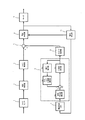
- step S101 the output of the torque sensor 1 phase-compensated by the phase compensator 2 is read into the microcomputer and stored in the memory.
- step S102 the current detection signal is read and stored in the memory.
- the current detection signal is obtained, for example, by detecting a voltage drop of the shunt resistor.
- step S103 the torque controller 3 reads the phase-compensated torque sensor output stored in the memory, maps the auxiliary torque current, and stores it in the memory.
- step S104 the current detection signal stored in the memory is read in the drive current HPF4 and a high-pass filter is calculated and stored in the memory as a drive current HPF output.
- step S105 the drive current HPF output is output in the vibration acceleration calculator 5a. Is multiplied by a gain to calculate the motor vibration acceleration in the motor rotation direction.
- step S106 the acceleration integrator 5b integrates the motor vibration acceleration to calculate the motor vibration speed in the motor rotation direction.
- the damping controller 6 reads the rotational speed calculator output stored in the memory, calculates the damping current by multiplying the control gain, and stores it in the memory.
- step S108 the adder 7 adds the auxiliary torque current and the damping current stored in the memory and stores them in the memory as a target current.
- step S109 PI control calculation is performed on the difference between the target current and the current detection signal, and a drive voltage command value is set. This drive voltage command value is output as a PWM signal, for example, and applied to the terminal of the motor 9 for driving.
- the operations from step S101 to S109 are repeated for each control sampling.
- the driving current HPF4 which is the steering component removing means will be described.
- the frequency at which the driver can steer is about 3 Hz or less.
- the steering frequency at the time of lane change is around 0.2 Hz, and usually such low frequency steering is often performed.
- the frequency band in which steering oscillation is likely to occur is 30 Hz or more, and frequency separation from the steering frequency is possible.
- a steering frequency component can be removed and only a vibration component can be obtained by using a high-pass filter represented by the transfer function of the following equation (1) as a frequency separator. it can.
- T 3 is a time constant, which is as follows when the break frequency is f 3 [Hz].
- T 3 1 / ⁇ f 3 ⁇ (2 ⁇ ) ⁇ (2)
- the corner frequency of the high-pass filter is set low, the steering component tends to remain, and if it is set high, the phase shift of the steering oscillation component of the current detection signal obtained through the high-pass filter increases.
- the break frequency of the high-pass filter is set to any frequency within the range of the frequency that causes steering oscillation from the steering frequency to be performed, the steering frequency component can be removed while leaving the steering oscillation component of the current detection signal. Is possible. Therefore, in the first embodiment, as the drive current HPF4, a high-pass filter whose break frequency is set in a range of 0.2 to 30 Hz is used, aiming at a maximum frequency that can be steered by a general driver, and a steering component is set. A steering oscillation component of the removed current detection signal is obtained.
- the relationship between the current and the motor torque is a known value as the torque constant Kt.
- Kt the torque constant
- the output of the drive current HPF4 by multiplying the output of the drive current HPF4 by the torque constant Kt and dividing by the rotational moment of inertia Jm, it can be converted into motor vibration acceleration in the motor rotation direction.
- the reaction torque from the torque sensor and the reaction torque from the tire are transmitted to the motor, but generally, the moment of inertia is proportional to the square of the vibration frequency, so that the reaction force from the torque sensor is high when the vibration frequency is high.
- the effect of reaction torque from tires and tires is relatively small and can be ignored. Therefore, by multiplying the output of the drive current HPF4 by the gain Kt / Jm, it can be converted into motor vibration acceleration in the motor rotation direction. Further, by integrating the motor vibration acceleration in the motor rotation direction, the motor vibration speed in the motor rotation direction can be obtained.
- the damping current is calculated based on the motor vibration speed calculated from the current detection signal from which the steering frequency component is removed. Even when the accuracy is not sufficiently high for torque vibration with extremely small output, accurate motor vibration speed can be estimated and damping control can be performed. In general, even if the torque proportional gain is increased, control system oscillation is prevented. Can do. Therefore, since the damping control gain of the damping controller 6 can be increased to make the damping work more effective, the steering torque can be reduced without the driver feeling the steering wheel vibration.
- FIG. FIG. 5 is a block diagram showing a configuration of an electric power steering control apparatus according to Embodiment 2 of the present invention. Since the parts other than the vibration speed estimator 5 that calculates the vibration component of the motor rotation speed from the drive current HPF have the same configuration as that of the first embodiment, the description thereof is omitted.
- the vibration speed estimator 5 multiplies the output of the drive current HPF4 by a gain to calculate the motor torque vibration acceleration in the motor rotation direction by the motor torque, and the reaction force torque from the torque sensor and the tire
- An acceleration adder 5e that adds the output of the reaction force torque acceleration calculator 5d that outputs the reaction force torque as an acceleration dimension
- an acceleration integrator 5b that integrates the output of the acceleration adder 5e to calculate the motor vibration speed in the motor rotation direction.
- the speed integrator 5c integrates the output of the acceleration integrator 5b and calculates the motor vibration angle in the motor rotation direction.
- the reaction force torque acceleration calculator 5d multiplies the motor vibration angle in the motor rotation direction calculated by the speed integrator 5c by a gain to obtain a reaction force torque acceleration signal.
- the motor vibration speed signal thus obtained is output to the damping controller 6 as in the first embodiment.
- step S301 the output of the torque sensor 1 phase-compensated by the phase compensator 2 is read into the microcomputer and stored in the memory.
- step S302 the current detection signal is read and stored in the memory.
- the current detection signal is obtained, for example, by detecting a voltage drop of the shunt resistor.
- step S303 the torque controller 3 reads the phase compensated torque sensor output stored in the memory, maps the auxiliary torque current, and stores it in the memory.
- step S304 the current detection signal stored in the memory is read in the drive current HPF4 and a high-pass filter is calculated and stored in the memory as a drive current HPF output.
- step S305 the drive current HPF is output in the vibration acceleration calculator 5a. Is multiplied by a gain to calculate the motor torque vibration acceleration in the motor rotation direction by the torque generated by the motor.
- step S306 the acceleration adder 5e adds the motor torque vibration acceleration signal calculated by the vibration acceleration calculator 5a and the reaction force torque acceleration signal calculated by the reaction torque acceleration calculator 5d and stored in the memory. And stored in a memory as a motor vibration acceleration signal.
- the acceleration integrator 5b integrates the motor vibration acceleration, calculates the motor vibration speed in the motor rotation direction, and stores it in the memory.
- step S308 the motor vibration speed signal is integrated in the speed integrator 5c, and the motor vibration angle signal is calculated and stored in the memory.
- step S309 the reaction force torque acceleration calculator multiplies the motor vibration angle signal by a gain to calculate a reaction force torque acceleration signal obtained by converting the reaction force torque from the torque sensor or the reaction force torque from the tire into the dimension of acceleration.
- step S310 the motor vibration speed stored in the memory in the acceleration integrator 5b is output to the damping controller 6.
- step S311 the damping controller 6 calculates the damping current by multiplying the motor vibration speed by the control gain and stores it in the memory.
- step S312 the adder 7 adds the auxiliary torque current and the damping current stored in the memory and stores them in the memory as a target current.
- step S313 PI control calculation is performed on the difference between the target current and the current detection signal, and a drive voltage command value is set. This drive voltage command value is output as a PWM signal, for example, and applied to the terminal of the motor 9 for driving.
- the operations from step S301 to step S313 are repeated for each control sampling.
- a map showing the relationship between the torque sensor output used in step S303 and the auxiliary torque current, a gain for converting the drive current HPF output used in step S305 into vibration acceleration in the motor rotation direction, and the motor used in step S309 A map, proportionality coefficient, etc. necessary for calculating target current such as gain for calculating reaction force torque acceleration signal by multiplying vibration angle signal by gain, control gain for calculating damping current used in step S310 above These constants are set in the ROM in advance.
- step S305 to S309 since the operation from step S305 to S309 is different from the first embodiment, this part will be further described.
- the relationship between the current and the motor torque is a known value as the torque constant Kt as described above. By dividing this by the rotational moment of inertia Jm, it can be converted into motor torque vibration acceleration in the motor rotation direction. At this time, the reaction torque from the torque sensor neglected in the first embodiment and the reaction torque from the tire are also transmitted to the motor with little influence. Further, since these torques are predominantly caused by the torsion bar of the torque sensor and the torsional deformation of the tire, the torque is proportional to the rotation angle, and the steering frequency component is removed by the drive current HPF4.
- vibration torque in the motor rotation direction can be obtained. Therefore, by dividing this vibration torque by the rotational moment of inertia Jm, it can be converted into vibration acceleration in the motor rotation direction. Therefore, by multiplying the motor vibration angle signal by the gain Ks / Jm, it is possible to convert the reaction force torque vibration acceleration in the motor rotation direction. As described above, by adding the reaction torque torque acceleration to the motor torque vibration acceleration, it is possible to calculate a more accurate motor vibration acceleration in the direction of motor rotation. The motor vibration speed in the rotation direction can be obtained.
- the sum of the motor vibration acceleration calculated from the current detection signal from which the steering frequency component has been removed and the torque vibration acceleration due to the torsion bar of the torque sensor or the torsional deformation of the tire is calculated. Since the damping current is calculated based on the motor vibration speed, it is possible to estimate the accurate motor vibration speed and perform the damping control even when using a torque detecting means that is inexpensive and not sufficiently accurate as described above. In general, even if the torque proportional gain is increased, oscillation of the control system can be prevented. Therefore, since the damping control gain of the damping controller 6 can be increased to make the damping work more effective, the steering torque can be reduced without the driver feeling the steering wheel vibration.
- the signal input to the drive current HPF is the output of the current detector 10, but it may be the target current.
- the output of the current detector 10 when the output of the current detector 10 is set as a target current, the configuration is shown in the block diagram of FIG. 3 and the flowchart of FIG. At this time, the target current may be the value calculated in the previous sampling.
- the configuration is shown in the block diagram of FIG. 7 and the flowchart of FIG.
- the induced voltage is known to be proportional to the motor rotation speed, it can be obtained by using a motor rotation speed sensor such as a resolver.
- the frequency that can be steered by the driver is generally about 3 Hz or less, and the induced voltage is dominated by the steering frequency component. Any characteristic can be used as long as it can be detected without causing a gain shift.
- current control there is a method that does not have a current detection means and performs current control from the target current and the induced voltage calculation value, and the configuration described in this paragraph is also applicable to the electric power steering control device of such a method. Is possible.
- T 4 s / (T 4 s + 1) (3)
- the transfer function of the integrator is 1 / s (4) Therefore, by integrating the signal that has passed through the high-pass filter, the following transfer function is obtained by multiplying the low-pass filter by the gain.
- T 4 / (T 4 s + 1) (5)
- T 4 is a time constant, which is as follows with the break frequency being f 4 [Hz].
- T 4 1 / ⁇ f 4 ⁇ (2 ⁇ ) ⁇ (6)
- T 4 1 / ⁇ f 4 ⁇ (2 ⁇ ) ⁇ (6)
Landscapes
- Engineering & Computer Science (AREA)
- Chemical & Material Sciences (AREA)
- Combustion & Propulsion (AREA)
- Transportation (AREA)
- Mechanical Engineering (AREA)
- Steering Control In Accordance With Driving Conditions (AREA)
- Power Steering Mechanism (AREA)
Abstract
Description
実施の形態1.
図1は、本発明の実施の形態1に係わる電動式パワーステアリング制御装置の構成を示すブロック図である。同図において、運転者が操舵した場合の操舵トルクを検出するトルクセンサ1の出力信号は、位相補償器2により位相補償され、その周波数特性が改善される。ついで、位相補償器2により位相補償されたトルクセンサ1の出力に基づいて、トルク制御器3により、上記操舵トルクを補助する補助トルク電流が演算される。
一方、操舵成分除去手段である駆動電流ハイパスフィルタ(以下、駆動電流HPFという)4は、電流検出器10で検出された電流検出信号から操舵周波数成分を除去する。ついで、振動速度推定器5は、上記の駆動電流HPFの出力から、モータ回転速度の振動成分を演算する。ここで、振動速度推定器5は、上記駆動電流HPFの出力にゲインを乗じてモータトルクによるモータ回転方向の振動加速度を演算する振動加速度演算器5aと、これを積分しモータ回転方向の振動速度を演算する加速度積分器5bを構成要素として含む。そして、ダンピング制御器6は、上記振動速度推定器5の出力であるモータ振動速度信号に基づいて操舵の減衰特性を制御するためのダンピング電流を演算する。
次いで、トルク制御器3で演算された補助トルク電流と、ダンピング制御器6で演算されたダンピング電流とが、加算器7で加算され目標電流が演算される。そして、電流制御器8の出力端では、モータ9に通電される電流が上記目標電流に一致するように制御される。モータ9がアシストトルクを発生すべく、例えば目標電流と電流検出信号の差に対してPI制御演算を行うことにより、モータ9の入力端子に印加する駆動電圧指令値を設定する。この駆動電圧指令値は、例えばPWM信号として出力される。
ステップS101で、位相補償器2で位相補償されたトルクセンサ1の出力をマイコンに読み込みメモリに記憶し、ステップS102で、電流検出信号を読み込みメモリに記憶する。電流検出信号は例えばシャント抵抗の電圧降下を検出することにより得られる。次に、ステップS103において、トルク制御器3により、上記メモリに記憶された位相補償後のトルクセンサ出力を読み込み、補助トルク電流をマップ演算しメモリに記憶する。
ステップS104では、駆動電流HPF4において、上記メモリに記憶された電流検出信号を読み込みハイパスフィルタの演算を行い駆動電流HPF出力としてメモリに記憶し、ステップS105では、振動加速度演算器5aにおいて駆動電流HPF出力にゲインを乗じてモータ回転方向のモータ振動加速度を演算する。ステップS106では加速度積分器5bにおいてモータ振動加速度を積分演算しモータ回転方向のモータ振動速度を演算する。ステップS107において、ダンピング制御器6により、上記メモリに記憶された回転速度演算器出力を読み込み、制御ゲインを乗じてダンピング電流を演算しメモリに記憶する。ステップS108では、加算器7において、上記メモリに記憶された補助トルク電流とダンピング電流とを加算し、目標電流としてメモリに記憶する。ステップS109では、目標電流と電流検出信号の差に対してPI制御演算を行い、駆動電圧指令値を設定する。この駆動電圧指令値は例えばPWM信号として出力しモータ9の端子に印加し駆動する。上記ステップS101からS109までの動作を、制御サンプリング毎に繰り返す。
一般に運転者が操舵可能な周波数は3Hz程度以下である。また、例えばレーンチェンジ時の操舵周波数は、0.2Hz付近であり、通常はこのような低周波の操舵を行うケースが多い。これに対し、ステアリング発振を生じやすい周波数帯域は30Hz以上であり、操舵周波数との周波数分離が可能である。
T3s/(T3s+1) (1)
ここでT3は時定数であり、折点周波数をf3[Hz]とすると下記となる。
T3=1/{f3×(2π)} (2)
従って、駆動電流HPF4の出力にゲインKt/Jmを乗じることによりモータ回転方向のモータ振動加速度に変換することができる。
さらにモータ回転方向のモータ振動加速度を積分演算することにより、モータ回転方向のモータ振動速度を得ることができる。
図5は、本発明の実施の形態2に係わる電動式パワーステアリング制御装置の構成を示すブロック図である。駆動電流HPFからモータ回転速度の振動成分を演算する振動速度推定器5以外の部分は、実施の形態1と全く同一の構成であるので説明を省略する。振動速度推定器5は、駆動電流HPF4の出力にゲインを乗じて、モータトルクによるモータ回転方向のモータトルク振動加速度を演算する振動加速度演算器5aと、トルクセンサからの反力トルクやタイヤからの反力トルクを加速度の次元として出力する反力トルク加速度演算器5dの出力を加算する加速度加算器5e、加速度加算器5eの出力を積分しモータ回転方向のモータ振動速度を演算する加速度積分器5b、加速度積分器5bの出力を積分しモータ回転方向のモータ振動角度を演算する速度積分器5cよりなる。反力トルク加速度演算器5dは、速度積分器5cで演算されたモータ回転方向のモータ振動角度にゲインを乗じて反力トルク加速度信号を得る。このようにして得られたモータ振動速度信号を実施の形態1と同様にダンピング制御器6に出力する。
ステップS301で、位相補償器2で位相補償されたトルクセンサ1の出力をマイコンに読み込みメモリに記憶し、ステップS302で、電流検出信号を読み込みメモリに記憶する。電流検出信号は例えばシャント抵抗の電圧降下を検出することにより得られる。
次に、ステップS303において、トルク制御器3により、上記メモリに記憶された位相補償後のトルクセンサ出力を読み込み、補助トルク電流をマップ演算しメモリに記憶する。
ステップS304では、駆動電流HPF4において、上記メモリに記憶された電流検出信号を読み込みハイパスフィルタの演算を行い駆動電流HPF出力としてメモリに記憶し、ステップS305では、振動加速度演算器5aにおいて駆動電流HPF出力にゲインを乗じてモータが発生するトルクによるモータ回転方向のモータトルク振動加速度を演算する。ステップS306では、加速度加算器5eにおいて、振動加速度演算器5aで演算されたモータトルク振動加速度信号と、反力トルク加速度演算器5dで演算しメモリに記憶された反力トルク加速度信号とを加算演算しモータ振動加速度信号としてメモリに記憶する。ステップS307では加速度積分器5bにおいてモータ振動加速度を積分演算しモータ回転方向のモータ振動速度を演算しメモリに記憶する。ステップS308では速度積分器5cにおいてモータ振動速度信号を積分して、モータ振動角度信号を演算しメモリに記憶する。ステップS309では反力トルク加速度演算器において、モータ振動角度信号にゲインを乗じて、トルクセンサからの反力トルクやタイヤからの反力トルクを加速度の次元に変換した反力トルク加速度信号を演算しメモリに記憶する。ステップS310では加速度積分器5bにおいてメモリに記憶されたモータ振動速度をダンピング制御器6に出力する。
以上のように、モータトルク振動加速度に反力トルク振動加速度を加算することにより、より正確なモータ回転方向のモータ振動加速度を演算することができ、これを積分演算することにより、より正確なモータ回転方向のモータ振動速度を得ることができる。
T4s/(T4s+1) (3)
積分器の伝達関数は
1/s (4)
であるので、ハイパスフィルタを通した信号を積分することにより、ローパスフィルタにゲインを乗じた下記の伝達関数となる。
T4/(T4s+1) (5)
ここでT4は時定数であり、折点周波数をf4[Hz]とする下記となる。
T4=1/{f4×(2π)} (6)
時定数は、例えば30Hzで振動が発生する場合は、折点周波数f4を30Hz以下など振動周波数以下の範囲に設定する。
この場合、折点周波数f4以下の周波数範囲では積分されない擬似積分しとなるので、信号にオフセットがある場合にも積分によるドリフトを防止することができる。
Claims (4)
- 運転者による操舵トルクをトーションバーの相対角から検出する操舵トルク検出手段と、上記検出された操舵トルク信号に基づいて上記操舵トルクを補助する補助トルク電流を演算するトルク制御器と、
上記操舵トルクを補助するトルクを発生するモータと、
上記モータに通電される電流の検出値もしくは指令値から操舵による成分を除去する電流操舵成分除去手段と、
上記モータの回転方向の振動速度を推定する振動速度推定手段と、
上記推定されたモータ振動速度の推定値を用いて、上記補助トルク電流に加算されるダンピング電流を演算するダンピング制御器と、
を備えた電動式パワーステアリング制御装置であって、
上記振動速度推定手段は、電流操舵成分除去手段から出力されるモータ電流に積算してモータの回転方向の振動加速度を演算する振動加速度演算手段と、
振動加速度演算手段出力を積分してモータ回転方向の振動速度を演算する回転加速度積分手段と、
を備えたことを特徴とする電動式パワーステアリング制御装置。 - 上記モータの回転方向の振動速度を推定する振動速度推定手段の出力を積分してモータの回転方向の振動角度を演算する速度積分手段と、
上記回転方向の振動角度から、トルクセンサからの反力トルクやタイヤからの反力トルクを加速度の次元として出力する反力トルク加速度を演算する反力トルク加速度演算手段と、
上記電流操舵成分除去手段から出力されるモータ電流に積算してモータの回転方向の振動加速度を演算したモータトルク振動加速度演算手段の出力を加算し、モータ振動加速度を演算する加速度加算手段と、
を有し、
上記回転加速度積分手段は、上記加速度加算手段出力を積分演算することを特徴とする請求項1記載の電動式パワーステアリング制御装置。 - 折点周波数が上記モータの回転方向の振動周波数以下の周波数の範囲に設定されたハイパスフィルタを、上記回転加速度積分手段あるいは上記速度積分手段に挿入することを特徴とする請求項1または請求項2に記載の電動式パワーステアリング制御装置。
- 上記電流操舵成分除去手段への入力信号は、電流検出器の出力あるいは目標電流であることを特徴とする請求項1乃至請求項3の何れか1の請求項に記載の電動式パワーステアリング制御装置。
Priority Applications (5)
| Application Number | Priority Date | Filing Date | Title |
|---|---|---|---|
| KR1020117001586A KR101191031B1 (ko) | 2008-07-30 | 2008-11-04 | 전동식 파워 스티어링 제어 장치 |
| JP2010522536A JP5140158B2 (ja) | 2008-07-30 | 2008-11-04 | 電動式パワーステアリング制御装置 |
| CN2008801298190A CN102066182B (zh) | 2008-07-30 | 2008-11-04 | 电动助力转向控制装置 |
| US12/990,958 US8548684B2 (en) | 2008-07-30 | 2008-11-04 | Electric power steering control apparatus |
| EP08876655.5A EP2305538B1 (en) | 2008-07-30 | 2008-11-04 | Motor-driven power steering control device |
Applications Claiming Priority (2)
| Application Number | Priority Date | Filing Date | Title |
|---|---|---|---|
| JP2008195889 | 2008-07-30 | ||
| JP2008-195889 | 2008-07-30 |
Publications (1)
| Publication Number | Publication Date |
|---|---|
| WO2010013298A1 true WO2010013298A1 (ja) | 2010-02-04 |
Family
ID=41610024
Family Applications (1)
| Application Number | Title | Priority Date | Filing Date |
|---|---|---|---|
| PCT/JP2008/003165 Ceased WO2010013298A1 (ja) | 2008-07-30 | 2008-11-04 | 電動式パワーステアリング制御装置 |
Country Status (6)
| Country | Link |
|---|---|
| US (1) | US8548684B2 (ja) |
| EP (1) | EP2305538B1 (ja) |
| JP (1) | JP5140158B2 (ja) |
| KR (1) | KR101191031B1 (ja) |
| CN (1) | CN102066182B (ja) |
| WO (1) | WO2010013298A1 (ja) |
Families Citing this family (11)
| Publication number | Priority date | Publication date | Assignee | Title |
|---|---|---|---|---|
| KR101606231B1 (ko) * | 2012-07-26 | 2016-04-01 | 주식회사 만도 | 전동식 조향 장치 및 그의 제어방법 |
| DE102015112360B4 (de) * | 2014-07-30 | 2020-07-09 | Steering Solutions IP Holding Corp. | Modul zur radunwuchtabweisung |
| JP6287767B2 (ja) * | 2014-11-10 | 2018-03-07 | 株式会社デンソー | モータ制御装置 |
| US9966890B2 (en) * | 2016-02-16 | 2018-05-08 | Steering Solutions Ip Holding Corporation | Detection of offset errors in phase current measurement for motor control system |
| US9873450B2 (en) * | 2016-02-16 | 2018-01-23 | Steering Solutions Ip Holding Corporation | Detection of offset errors in phase current measurement for motor control system |
| JP7115135B2 (ja) * | 2018-08-13 | 2022-08-09 | 株式会社アイシン | モータ制御装置 |
| JP7342876B2 (ja) * | 2018-09-26 | 2023-09-12 | ニデック株式会社 | ステアリング制御装置およびパワーステアリング装置 |
| JP7154425B2 (ja) * | 2019-09-02 | 2022-10-17 | 東芝三菱電機産業システム株式会社 | 電力変換装置及び電動機ドライブシステム |
| JP7452688B2 (ja) * | 2020-10-09 | 2024-03-19 | 日産自動車株式会社 | 転舵方法及び転舵装置 |
| US12172706B2 (en) * | 2021-09-29 | 2024-12-24 | Nidec Corporation | Motor control device, motor control method, motor module, and electric power steering device |
| CN119218294A (zh) * | 2023-06-29 | 2024-12-31 | 尼得科株式会社 | 控制装置和转向装置 |
Citations (5)
| Publication number | Priority date | Publication date | Assignee | Title |
|---|---|---|---|---|
| JP2000168600A (ja) | 1998-12-01 | 2000-06-20 | Mitsubishi Electric Corp | 電動式パワーステアリング制御装置 |
| JP2006335228A (ja) * | 2005-06-02 | 2006-12-14 | Mitsubishi Electric Corp | 電動パワーステアリング制御装置 |
| JP2007112189A (ja) * | 2005-10-18 | 2007-05-10 | Mitsubishi Electric Corp | 電動パワーステアリング制御装置 |
| JP2007161006A (ja) * | 2005-12-12 | 2007-06-28 | Mitsubishi Electric Corp | 電動パワーステアリング制御装置 |
| JP2008001322A (ja) * | 2006-06-26 | 2008-01-10 | Nissan Motor Co Ltd | パワーステアリング装置及び振動状態検出方法 |
Family Cites Families (4)
| Publication number | Priority date | Publication date | Assignee | Title |
|---|---|---|---|---|
| JPS60148392A (ja) * | 1984-01-11 | 1985-08-05 | Hitachi Ltd | 電動機の回転制御装置 |
| JP4060805B2 (ja) * | 2004-01-05 | 2008-03-12 | 三菱電機株式会社 | 電動機のトルク制御装置及び電動機のトルク制御方法及び電動機の回転子位置検出装置及び電動機の回転子位置検出方法及び密閉型圧縮機及び冷凍空調装置 |
| EP2371676B1 (en) * | 2006-04-13 | 2013-09-04 | Mitsubishi Electric Corporation | Electric power steering control system |
| WO2009122606A1 (ja) | 2008-04-04 | 2009-10-08 | 三菱電機株式会社 | 電動式パワーステアリング制御装置 |
-
2008
- 2008-11-04 US US12/990,958 patent/US8548684B2/en not_active Expired - Fee Related
- 2008-11-04 JP JP2010522536A patent/JP5140158B2/ja not_active Expired - Fee Related
- 2008-11-04 KR KR1020117001586A patent/KR101191031B1/ko not_active Expired - Fee Related
- 2008-11-04 WO PCT/JP2008/003165 patent/WO2010013298A1/ja not_active Ceased
- 2008-11-04 EP EP08876655.5A patent/EP2305538B1/en not_active Not-in-force
- 2008-11-04 CN CN2008801298190A patent/CN102066182B/zh not_active Expired - Fee Related
Patent Citations (5)
| Publication number | Priority date | Publication date | Assignee | Title |
|---|---|---|---|---|
| JP2000168600A (ja) | 1998-12-01 | 2000-06-20 | Mitsubishi Electric Corp | 電動式パワーステアリング制御装置 |
| JP2006335228A (ja) * | 2005-06-02 | 2006-12-14 | Mitsubishi Electric Corp | 電動パワーステアリング制御装置 |
| JP2007112189A (ja) * | 2005-10-18 | 2007-05-10 | Mitsubishi Electric Corp | 電動パワーステアリング制御装置 |
| JP2007161006A (ja) * | 2005-12-12 | 2007-06-28 | Mitsubishi Electric Corp | 電動パワーステアリング制御装置 |
| JP2008001322A (ja) * | 2006-06-26 | 2008-01-10 | Nissan Motor Co Ltd | パワーステアリング装置及び振動状態検出方法 |
Non-Patent Citations (1)
| Title |
|---|
| See also references of EP2305538A4 |
Also Published As
| Publication number | Publication date |
|---|---|
| KR101191031B1 (ko) | 2012-10-16 |
| EP2305538A1 (en) | 2011-04-06 |
| EP2305538B1 (en) | 2014-07-23 |
| CN102066182B (zh) | 2012-11-28 |
| US8548684B2 (en) | 2013-10-01 |
| JPWO2010013298A1 (ja) | 2012-01-05 |
| EP2305538A4 (en) | 2013-04-03 |
| US20110054740A1 (en) | 2011-03-03 |
| CN102066182A (zh) | 2011-05-18 |
| JP5140158B2 (ja) | 2013-02-06 |
| KR20110025213A (ko) | 2011-03-09 |
Similar Documents
| Publication | Publication Date | Title |
|---|---|---|
| JP5140158B2 (ja) | 電動式パワーステアリング制御装置 | |
| JP4999984B2 (ja) | 電動式パワーステアリング制御装置 | |
| JP4203062B2 (ja) | 車両用操舵装置 | |
| EP3072784B1 (en) | Motor-driven power steering apparatus | |
| WO2014136516A1 (ja) | 電動パワーステアリング装置 | |
| EP2998201B1 (en) | Control apparatus for electric-powered power steering apparatus | |
| WO2019235609A1 (ja) | 電動パワーステアリング装置 | |
| JPWO2019167661A1 (ja) | 車両用操向装置 | |
| WO2020115973A1 (ja) | 車両用操向装置 | |
| JP4227133B2 (ja) | 電動パワーステアリング制御装置 | |
| JP7222309B2 (ja) | 車両用操向装置 | |
| JP2009096325A (ja) | ステアリング装置の故障検知装置 | |
| JP4347871B2 (ja) | 車両用操舵制御装置 | |
| JP2006315617A (ja) | 車両用操舵制御装置 | |
| JP4223501B2 (ja) | 電動式パワーステアリング制御装置 | |
| JP4129021B2 (ja) | 車両用操舵制御装置 | |
| JP4098807B2 (ja) | 車両用操舵制御装置 | |
| JP5040414B2 (ja) | 電動パワーステアリング装置の制御装置 | |
| JP5739085B2 (ja) | 電動パワーステアリング装置 | |
| JP2008247248A (ja) | 車両用操舵装置 | |
| JP2006076484A (ja) | 電動パワーステアリング装置の制御装置 | |
| JP2011088486A (ja) | 電動パワーステアリング装置 |
Legal Events
| Date | Code | Title | Description |
|---|---|---|---|
| WWE | Wipo information: entry into national phase |
Ref document number: 200880129819.0 Country of ref document: CN |
|
| 121 | Ep: the epo has been informed by wipo that ep was designated in this application |
Ref document number: 08876655 Country of ref document: EP Kind code of ref document: A1 |
|
| WWE | Wipo information: entry into national phase |
Ref document number: 2010522536 Country of ref document: JP |
|
| WWE | Wipo information: entry into national phase |
Ref document number: 12990958 Country of ref document: US |
|
| ENP | Entry into the national phase |
Ref document number: 20117001586 Country of ref document: KR Kind code of ref document: A |
|
| WWE | Wipo information: entry into national phase |
Ref document number: 2008876655 Country of ref document: EP |
|
| NENP | Non-entry into the national phase |
Ref country code: DE |