WO2010016114A1 - 回路遮断器の可動接触子装置 - Google Patents
回路遮断器の可動接触子装置 Download PDFInfo
- Publication number
- WO2010016114A1 WO2010016114A1 PCT/JP2008/064104 JP2008064104W WO2010016114A1 WO 2010016114 A1 WO2010016114 A1 WO 2010016114A1 JP 2008064104 W JP2008064104 W JP 2008064104W WO 2010016114 A1 WO2010016114 A1 WO 2010016114A1
- Authority
- WO
- WIPO (PCT)
- Prior art keywords
- pair
- movable contact
- contact
- portions
- movable
- Prior art date
- Legal status (The legal status is an assumption and is not a legal conclusion. Google has not performed a legal analysis and makes no representation as to the accuracy of the status listed.)
- Ceased
Links
Images




Classifications
-
- H—ELECTRICITY
- H01—ELECTRIC ELEMENTS
- H01H—ELECTRIC SWITCHES; RELAYS; SELECTORS; EMERGENCY PROTECTIVE DEVICES
- H01H1/00—Contacts
- H01H1/12—Contacts characterised by the manner in which co-operating contacts engage
- H01H1/14—Contacts characterised by the manner in which co-operating contacts engage by abutting
- H01H1/22—Contacts characterised by the manner in which co-operating contacts engage by abutting with rigid pivoted member carrying the moving contact
- H01H1/221—Contacts characterised by the manner in which co-operating contacts engage by abutting with rigid pivoted member carrying the moving contact and a contact pressure spring acting between the pivoted member and a supporting member
-
- H—ELECTRICITY
- H01—ELECTRIC ELEMENTS
- H01H—ELECTRIC SWITCHES; RELAYS; SELECTORS; EMERGENCY PROTECTIVE DEVICES
- H01H1/00—Contacts
- H01H1/12—Contacts characterised by the manner in which co-operating contacts engage
- H01H1/14—Contacts characterised by the manner in which co-operating contacts engage by abutting
- H01H1/22—Contacts characterised by the manner in which co-operating contacts engage by abutting with rigid pivoted member carrying the moving contact
- H01H1/221—Contacts characterised by the manner in which co-operating contacts engage by abutting with rigid pivoted member carrying the moving contact and a contact pressure spring acting between the pivoted member and a supporting member
- H01H2001/223—Contacts characterised by the manner in which co-operating contacts engage by abutting with rigid pivoted member carrying the moving contact and a contact pressure spring acting between the pivoted member and a supporting member using a torsion spring
-
- H—ELECTRICITY
- H01—ELECTRIC ELEMENTS
- H01H—ELECTRIC SWITCHES; RELAYS; SELECTORS; EMERGENCY PROTECTIVE DEVICES
- H01H77/00—Protective overload circuit-breaking switches operated by excess current and requiring separate action for resetting
- H01H77/02—Protective overload circuit-breaking switches operated by excess current and requiring separate action for resetting in which the excess current itself provides the energy for opening the contacts, and having a separate reset mechanism
- H01H77/10—Protective overload circuit-breaking switches operated by excess current and requiring separate action for resetting in which the excess current itself provides the energy for opening the contacts, and having a separate reset mechanism with electrodynamic opening
- H01H77/102—Protective overload circuit-breaking switches operated by excess current and requiring separate action for resetting in which the excess current itself provides the energy for opening the contacts, and having a separate reset mechanism with electrodynamic opening characterised by special mounting of contact arm, allowing blow-off movement
- H01H77/104—Protective overload circuit-breaking switches operated by excess current and requiring separate action for resetting in which the excess current itself provides the energy for opening the contacts, and having a separate reset mechanism with electrodynamic opening characterised by special mounting of contact arm, allowing blow-off movement with a stable blow-off position
Definitions
- This invention relates to an improvement of a movable contact device in a circuit breaker.
- a circuit breaker such as a circuit breaker for wiring or a circuit breaker includes a power supply side terminal connected to the power supply side of the distribution circuit, a load side terminal connected to the load side of the distribution circuit, and a power supply
- a movable contact device including a movable contact provided with a fixed contact provided on the side terminal and a movable contact connected to the load side terminal and capable of contacting or separating from the fixed contact, and driving the movable contact device
- An open / close mechanism that moves the movable contact to or away from the fixed contact, an operation handle that manually operates the open / close mechanism, and an automatic open / close when a predetermined overcurrent or leakage current flows through the power distribution circuit
- an automatic trip device that drives the mechanism to shut off the power distribution circuit.
- a movable contact device for such a circuit breaker, a plurality of movable contactors each having a movable contact at one end and having the other end penetrated by a shaft pin, Insulator crossbar that holds the shaft pin and supports each movable contactor rotatably around the shaft pin, and the movable contactor sandwiching the other end of the movable contactor from both sides in the axial direction of the shaft pin
- a holding piece made of a conductor that is in sliding contact with the other end of the wire, a flexible conductor having one end connected to the holding piece and the other end connected to the load side terminal, and movable when the circuit breaker is turned on.
- a configuration including a torsion coil spring that biases the movable contact in a direction in which a predetermined contact pressure is applied to the contact has been proposed (for example, see Patent Document 1).
- a notch portion is formed in the above-described sandwiching piece, and a shaft pin penetrating the other end portion of the movable contact by the notch portion is provided. It is configured to receive.
- the torsion coil spring described above is a connection in which one end portion is fixed to the crossbar and the shaft pin is inserted to form a compression spring and the other end portions of these coil portions are integrally connected.
- the connecting piece is configured to constantly urge the movable contact in the ON direction by pressing the connecting piece against the above-described movable contact.
- the conventional movable contact device described in Patent Document 1 because it is configured to receive the shaft pin that penetrates the other end of the movable contact by the notch formed in the clamping piece, the flexible conductor can be connected to the movable contact via the sandwiching piece. Further, the contact state between the movable contact and the sandwiching piece can be stabilized by pressing the sandwiching piece against the movable contact by the coil portion of the torsion coil spring, and the movable contact rotates around the shaft pin. In the meantime, it is possible to keep the movable contact and the flexible conductor in an electrically good contact state.
- the movable contactor, the torsion coil spring, and the shaft pin are combined with each other.
- the torsion coil spring is sandwiched between the movable contact and the crossbar, and the coil portion of the torsion coil spring is compressed to generate an urging force as a compression spring. Yes.
- the clamping piece in order to insert the clamping piece between the torsion coil spring and the movable contact, the clamping piece is slid on the side of the movable contact while the clamping piece is pressed against the side of the movable contact by the torsion coil spring. Will be done. As a result, scratches may occur on the side surface of the movable contact and the inner surface of the holding piece.
- the present invention has been made in order to solve the above-described problems in the movable contact device of the conventional circuit breaker.
- the movable contact device can be easily assembled, and the number of components can be reduced.
- the object of the present invention is to provide a movable contactor device with few circuit breakers.
- a movable contact device for a circuit breaker includes a pair of connecting conductor portions opposed to each other with a cross bar provided with a recess having an opening on a peripheral surface thereof and supported rotatably about an axis.
- a movable contact support member in which at least a part of the pair of connection conductors is fitted in the recess of the crossbar; a movable contact at one end; and the other end connected to the pair of connection conductors.
- a movable contact that is movably supported; and a contact pressure spring that urges the movable contact to apply a contact pressure to the movable contact when the movable contact and a fixed contact provided in a circuit breaker are in contact with each other.
- a movable contactor device for a circuit breaker comprising: the movable contactor, wherein the other end portion is disposed between the pair of connecting conductor portions, and both side surfaces of the other end portion are the pair of the pair.
- Each of the contact pressure springs is slidably in contact with the inner surface of the connecting conductor portion.
- the coil springs and the one ends of the pair of coil springs are connected to each other and extend toward one end of the movable contact to contact the movable contact and apply the contact pressure.
- An arm-shaped spring portion that urges the movable contact, and extends from the other end of each of the pair of coil springs in the opposite direction to the one end of the movable contact, when the contact pressure spring is fitted.
- a pair of feet that abut against the wall surface of the recess of the crossbar, and the recess of the crossbar includes a spring holding wall that abuts at least a part of the outer peripheral portion of the coil spring portion and holds the coil spring portion. It is characterized by having.
- the movable contact has the other end disposed between the pair of connection conductors, and both side surfaces of the other end are the pair of connection conductors.
- the contact pressure springs are slidably in contact with the inner side surfaces of the pair of connection conductor portions, and are fitted between the outer side surfaces of the pair of connection conductor portions and the side walls of the recesses of the crossbar.
- a pair of coil spring portions that are biased toward the other end portion of the movable contact and one end portions of the pair of coil spring portions are connected to each other and extend toward one end portion of the movable contact.
- a recess of the cross bar includes a spring holding wall that holds the coil spring portion in contact with at least a part of the outer peripheral portion of the coil spring portion.
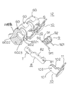
- FIG. 4 is an exploded perspective view showing the movable contact device according to the first embodiment of the present invention with a crossbar broken from a breaking line A in FIG. 3.
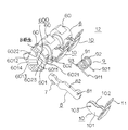
- FIG. 4 is an exploded perspective view showing the movable contact device according to the first embodiment of the present invention with a crossbar broken from a broken line B in FIG. 3.
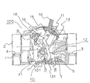
- Embodiment 1 a circuit breaker including a movable contact device according to Embodiment 1 of the present invention will be described.
- a base 1 and a cover 2 formed of a synthetic resin material are combined together by a screw (not shown) to constitute a housing of a circuit breaker 100 for three phases.
- a power supply side terminal 3 connected to the power supply side of a three-phase electric circuit (not shown) opened and closed by a circuit breaker 100, and a load side connected to the load side of the electric circuit described above.
- Terminal 4 is fixed.
- a fixed contact 5 is fixed to the end of the power supply side terminal 3.
- the cross bar 6 made of a synthetic resin material is supported by the base 1 so as to be rotatable around its axis.
- the movable contact 8 having the movable contact 7 at one end is inserted into a later-described recess of the cross bar 6 as described later.
- the contact pressure spring 9 is fitted in the aforementioned recess of the cross bar 6 and urges the movable contact 8 so as to apply a contact pressure to the movable contact 7 as will be described later.
- the movable contact supporting member 10 has a base 11 fixed to the base 1 and a pair of connecting conductors 101 and 102 that rise substantially vertically from the base 11 as will be described later (only 101 is shown in FIG. 1).
- connection conductor portions 101 and 102 are slidably electrically connected to the side surface of the other end portion of the movable contact 8 and the pair of connection conductor portions 101 and 102
- the other end of the movable contact 8 is rotatably supported.
- the base 11 of the movable contact support member 10 is connected to the load side terminal 4 via a load side connection conductor 41.
- the cross bar 6, the movable contact 7, the movable contact 8, the contact pressure spring 9, and the movable contact support member 10 constitute the movable contact device 12 according to the first embodiment of the present invention. Yes. Details of the configuration of the movable contact device 12 will be described later.
- the lower link 13 has one end rotatably connected to the cross bar 6 and the other end rotatably connected to one end of the upper link 14.
- One end portion of the operation mechanism portion 15 is rotatably supported by the base 1, and an operation handle 16 that is operated by an operator is fixed to the other end portion.
- the other end of the upper link 14 is rotatably connected to the other end of the operation mechanism unit 15.
- One end of the toggle spring 17 formed by the tension coil spring is fixed to the connecting portion between the lower link 13 and the upper link 14, and the other end is fixed to the other end of the operation mechanism portion 15.
- the upper link 14, the lower link 13, and the toggle spring 17 constitute a so-called toggle link mechanism.
- the operation mechanism unit 15 rotates around the one end portion in the direction of the closed position on the right side of the drawing.
- one end of the toggle spring 17 moves to the right in the drawing along with the rotation of the operation mechanism 15 and moves to the right beyond the connection point between the upper link 14 and the operation mechanism 15.
- the upper link 14 and the lower link 13 are aligned in the state shown in the figure by the pulling force of the toggle spring 17.
- the lower link 13 rapidly rotates the cross bar 6 in the clockwise direction, rotates the movable contact 8 in the clockwise direction, and contacts the movable contact 7 with the fixed contact 5.
- the electric circuit is closed.
- the movable contact 8 is urged by a contact pressure spring 9 and applies a predetermined contact pressure to the movable contact 7 that is in contact with the fixed contact 5.
- the automatic trip device 18 is engaged with a part of the upper link 14 when the operation handle 16 is in the illustrated closed position, that is, when the movable contact 7 is in contact with the fixed contact 5 to close the electric circuit. Thus, the upper link 14 is latched to rotate counterclockwise around the other end.
- the automatic trip mechanism 18 is provided with, for example, a time trip trip mechanism using bimetal and an instantaneous trip mechanism using an electromagnet.
- the time-release trip mechanism of the automatic trip device 18 When an overcurrent of a predetermined value or more continues to flow in the electric circuit for a predetermined time or longer, the time-release trip mechanism of the automatic trip device 18 operates to release the aforementioned latch. As a result, the upper link 18 rapidly rotates counterclockwise around the other end due to the pulling force of the toggle spring 17, and the lower link 13 is rapidly pulled upward in the figure, and at the same time the cross bar 6 is counterclockwise. Rotate in the direction. As a result, the movable contact 7 of the movable contact 8 is rapidly separated from the fixed contact 5 and interrupts the electric circuit. When an excessive current such as a short-circuit current flows in the electric circuit, the instantaneous trip mechanism of the automatic trip device 18 operates to release the aforementioned latch. As a result, the electric circuit is instantaneously interrupted by the same operation as that of the time-delay trip mechanism described above.
- the cross bar 6 is formed of a synthetic resin material as described above, and both end portions in the axial direction are rotatably supported by the base 1.
- the cross bar 6 has three movable contact mounting portions 60 for mounting the movable contact 8, the contact pressure spring 9, and the movable contact receiving member 10 corresponding to the U phase, V phase, and W phase, respectively. Are provided at equal intervals W.
- the cross bar 6 includes a concave portion 600 having an opening portion 6001 that opens on the peripheral surface of the cross bar in each of the movable contact mounting portions 60 described above.
- the recess 600 includes a through hole 601 that penetrates from the opening 6001 in a direction perpendicular to the axial direction of the crossbar 6, and openings 6021 and 6031 that are integrated with the opening 6001.
- a pair of recessed portions 602 and 603 that are recessed in the axial direction from both sides of the hole 601 in the axial direction are provided.
- the through hole 601 includes an opening 6012 that opens on the peripheral surface of the cross bar 6 on the opposite side to the opening 6011, and the above-described opening 6012 from the middle of the through hole 601.
- a concave groove 6013 extending to the top is provided.
- the pair of depressed portions 602 and 603 are U-shaped that abut against the outer peripheral portions of a pair of coil spring portions 91 and 92 of a contact pressure spring 9 to be described later and hold the outer diameters of the coil spring portions 91 and 92, respectively.
- a flat wall surface 6023 connected to the spring holding wall 6022.
- the spring holding wall and the flat wall surface of the depressed portion 603 are not shown in the drawing, they are formed in the same manner as the spring holding wall 2022 and the wall surface 6023 of the depressed portion 602.
- the internal space of the above-mentioned through-hole 601 and a pair of depression part 602,603 is mutually connected like illustration.
- Both side walls of the concave groove 6013 provided in the above-described through hole 601 protrude from the both side walls of the through hole 601 to the inside of the through hole 601 through the inclined surface 6014 (FIG. 5 shows only one side wall. Is displayed, but the other side wall is also formed in the same manner).
- the groove width of the concave groove 6013 is formed to be slightly larger than the thickness of the conductive member constituting the movable contact 8, and therefore the concave groove 6013 is formed on the cross bar 6 in the movable contact 8. This serves to regulate the movement of the lens in the axial direction.
- the movable contact support member 10 includes a base portion 11 fixed to the base 1 of the circuit breaker 100, and a pair of connection conductor portions 101 and 102 that are vertically raised from the base portion 11 and have tip portions facing each other in parallel.
- the pair of protrusions 103 provided so as to protrude from the opposing wall surfaces of the pair of connection conductors 101 and 102 (only the base portion 103 of the protrusion of the connection conductor 101 is shown in FIGS. 3 to 5). Display).
- the base portion 11 of the movable contact support member 10 is inserted into the rising portions of the connecting conductor portions 101 and 102 by inserting the aforementioned load side connecting conductor 41 against the elastic force of the rising portions.
- the side connection conductor 41 is electrically connected.
- the movable contact 8 has a movable contact 7 fixed at one end and a through hole 81 at the other end.
- the above-described pair of protrusions provided on the connection conductor portions 101 and 102 of the movable contact support member 10 are inserted from both sides of the movable contact 8.
- the other end part of the movable contact 8 is rotatably supported by the movable contact support member 10.
- the inner side surfaces of the connecting conductor portions 101 and 102 of the movable contact support member 10 are in electrical contact with both side surfaces of the movable contact 8 so as to be slidable.
- this configuration eliminates the need to connect a shunt wire made of a flexible conductive wire between the movable contact 8 and the load side connection conductor 41, and a so-called shuntless energization connection structure is provided. It is composed.
- the contact pressure spring 9 is configured as a double torsion type torsion coil spring. That is, the contact pressure spring 9 includes a pair of coil spring portions 91 and 92 as compression coil springs wound with a predetermined pitch angle, and a pair of the coil spring portions 91 and 92, respectively. An arm-like spring portion that connects the one end portions to each other, extends toward one end portion of the movable contact 8 and abuts against the back surface 82 of the movable contact 8 to urge the movable contact 8 to apply the contact pressure.
- the coil spring portion 91 of the contact pressure spring 9 is fitted in the depressed portion 603 of the cross bar 6, and the outer peripheral portion thereof is a spring holding wall (not shown) of the depressed portion 603 (not shown).
- the arm-shaped spring portion 93 comes into contact with the back surface of the movable contact 8 at point E, and the foot portion 911 hits the wall surface (not shown) of the depressed portion 603 at point F. Touch.
- the coil spring portion 91 is pressed in the H direction against the spring holding wall of the depressed portion 603 at the point G, and the outer diameter thereof is held. Therefore, it is possible to hold the outer diameter of the coil spring portions 91 and 92 and to attach the shaft pin to the cross bar 6 without penetrating the shaft pins through the coil spring portions 91 and 92 as in the prior art.
- the arm-shaped spring portion 93 of the contact pressure spring 9 is brought into contact with the back surface 82 of the movable contact 12, and the axially inner end portions of the pair of coil spring portions 91 and 92 of the contact pressure spring 9 are moved to the movable contact.
- the outer surfaces of the pair of connecting conductor portions 101 and 102 of the support member 10 are brought into contact with each other.
- the contact springs 9 and the other end of the movable contact 8 and the movable contact support member 10 are sandwiched between the connection conductor portions 101 and 102 of the movable contact support member 10 by the pair of coil spring portions 91 and 92. Attach to.
- the movable contact 8 is inserted into the through hole 601 from the opening 6001 of the cross bar 6 shown in FIGS. 3 to 4, and one end of the movable contact 8 passes through the through hole 601. Project from the opening 6012.
- the contact pressure spring 9 is inserted into the pair of recessed portions 602 and 603 of the crossbar 6 from the respective openings 6021 and 6031 while the coil spring portions 91 and 92 are compressed.
- a part of the outer peripheral portion of 92 is in contact with the U-shaped spring holding wall 6022 of the respective recessed portions 602 and 603.
- the pair of feet 911 and 921 of the contact pressure spring 9 is inserted into the recesses 602 and 603 of the pair of recesses 603 during the insertion operation. It naturally abuts against the wall surface 6023. Further, when the coil spring portions 91 and 92 of the contact pressure spring 9 are inserted into the recessed portions 602 and 603 and released from the above-described gripping, they are extended in the axial direction by the spring force, and the outer end portions in the axial direction thereof. Comes into contact with the side wall portions of the respective recessed portions 602 and 603. At this time, the coil spring portions 91 and 92 hold the compressed state.
- the inner end of the contact pressure spring 9 in the axial direction presses the connection conductors 101 and 102 of the movable contact support member 10 toward the both side surfaces of the movable contact 8 by the spring force.
- the contact pressure as the shuntless contact portion between the movable contact 8 and the connection conductor portions 101 and 102 of the movable contact support member 10 is maintained, and both are slidable and kept in electrical connection. It is.
- the assembly work of the movable contact device 12 is thus completed, and the movable contact device 12 shown in FIGS. 2 and 7 is configured.
- the movable contact device 12 of the circuit breaker according to the first embodiment of the present invention can be mounted on the crossbar 6 with the movable contact 8 and the movable contact supporting member 10 connected.
- the foot portions 911 and 921 of the contact pressure spring 9 are engaged with the wall surface of the recess only by the operation of compressing the coil spring portions 91 and 92 of the contact pressure spring 9 and inserting them into the recess 600 of the crossbar 6. Since a predetermined rotational moment to the movable contact 8 can be obtained, the springing work of the foot portions 911 and 921 of the contact pressure spring after the contact pressure spring 9 is inserted becomes unnecessary, and the assembly time can be shortened. .
- the contact pressure spring 9 is held. This eliminates the need for a shaft pin or the like to reduce the number of parts. Further, the side surfaces of the movable contact and the inner surface of the connecting conductor portion are not scratched during assembly unlike conventional devices, and the life can be extended.
- the present invention can be used in the field of circuit breakers such as a circuit breaker for wiring and a circuit breaker for wiring.
Landscapes
- Breakers (AREA)
Abstract
Description
先ず、この発明の実施の形態1による可動接触子装置を備えた回路遮断器について説明する。図1に於いて、合成樹脂材料で形成されたベース1とカバー2とは、ネジ(図示せず)により一体に組み合わされて3相用の回路遮断器100の筐体を構成する。ベース1の内部には、回路遮断器100により開閉される3相電気回路(図示せず)の電源側に接続される電源側端子3と、前述の電気回路の負荷側に接続される負荷側端子4が固定されている。電源側端子3の端部には固定接点5が固定されている。
Claims (5)
- 周面に開口部を有する凹部を備え軸心の周りに回動自在に支持されるクロスバーと、間隔を介して対向する一対の接続導体部を有し前記一対の接続導体部の少なくとも一部分が前記クロスバーの前記凹部に嵌装される可動接触子支持部材と、一端部に可動接点を備え他端部が前記一対の接続導体部に回動自在に支持される可動接触子と、前記可動接点と回路遮断器に設けられた固定接点との接触時に前記可動接点に接触圧力を付与すべく前記可動接触子を付勢する接圧ばねとを備えた回路遮断器の可動接触子装置であって、前記可動接触子は、前記他端部が前記1対の接続導体部の間に配置され、前記他端部の両側面が前記一対の接続導体部の内側面に夫々摺動可能に接触し、前記接圧ばねは、前記一対の接続導体部の夫々の外側面と前記クロスバーの凹部の側壁との間に嵌装され前記1対の接続導体部を前記可動接触子の前記他端部側に付勢する1対のコイルばね部と、前記1対のコイルばね部の夫々の一端部を相互に連結して前記可動接触子の一端部側に延び前記可動接触子に当接して前記接触圧力を付与すべく前記可動接触子を付勢する腕状ばね部と、前記一対のコイルばね部の夫々の他端部から前記可動接触子の一端部側とは逆の方向に延び前記接圧ばねの嵌装時に前記クロスバーの凹部の壁面に当接する一対の足部とを備え、前記クロスバーの凹部は、前記コイルばね部の外周部の少なくとも一部に当接して前記コイルばね部を保持するばね保持壁を備えていることを特徴とする回路遮断器の可動接触子装置。
- 前記クロスバーの凹部は、前記クロスバーを前記開口部から前記クロスバーの軸方向に対して直交する方向に貫通する貫通孔と、前記開口部に於いて開口し前記貫通孔の前記軸方向の両側から前記軸方向に夫々陥没すると共に前記ばね保持壁を備えた1対の陥没部とを備え、前記可動接触子は、前記他端部の少なくとも一部分が前記貫通孔内に挿入され前記一端部が前記貫通孔を貫通して前記クロスバーの周面から突出しており、前記一対の接続導体部の少なくとも一部分が前記貫通孔に嵌装され、前記1対のコイルばね部は、前記1対の接続導体部の外側表面と前記1対の陥没部の側壁との間に夫々嵌装されていることを特徴とする請求項1に記載の回路遮断器の可動接触子装置。
- 前記貫通孔は、前記可動接触子の前記軸方向の移動を規制する凹溝を備えていることを特徴とする請求項2に記載の回路遮断器の可動接触子装置。
- 前記1対の陥没部は、前記1対のコイルばね部の夫々の外周部に当接して夫々のコイルばね部の外径を保持するU字状のばね保持壁を備えていることを特徴とする請求項2に記載の回路遮断器の可動接触子装置。
- 前記クロスバーの凹部は、前記1対の接続導体部の外側面に前記1対のコイルばね部が装着された状態で前記接圧ばねを前記1対の接続導体部と共に前記開口部から前記嵌装し得るように構成され、前記接圧ばねは、前記嵌装時に前記1対の足部が前記凹部の壁面に夫々当接するように構成されていることを特徴とする請求項1に記載の回路遮断器の可動接触子装置。
Priority Applications (4)
| Application Number | Priority Date | Filing Date | Title |
|---|---|---|---|
| JP2010523673A JP5134085B2 (ja) | 2008-08-06 | 2008-08-06 | 回路遮断器の可動接触子装置 |
| EP08808716.8A EP2323155B1 (en) | 2008-08-06 | 2008-08-06 | Movable contactor device of circuit breaker |
| CN200880129406.2A CN102047371B (zh) | 2008-08-06 | 2008-08-06 | 断路器的可动触头装置 |
| PCT/JP2008/064104 WO2010016114A1 (ja) | 2008-08-06 | 2008-08-06 | 回路遮断器の可動接触子装置 |
Applications Claiming Priority (1)
| Application Number | Priority Date | Filing Date | Title |
|---|---|---|---|
| PCT/JP2008/064104 WO2010016114A1 (ja) | 2008-08-06 | 2008-08-06 | 回路遮断器の可動接触子装置 |
Publications (1)
| Publication Number | Publication Date |
|---|---|
| WO2010016114A1 true WO2010016114A1 (ja) | 2010-02-11 |
Family
ID=41663344
Family Applications (1)
| Application Number | Title | Priority Date | Filing Date |
|---|---|---|---|
| PCT/JP2008/064104 Ceased WO2010016114A1 (ja) | 2008-08-06 | 2008-08-06 | 回路遮断器の可動接触子装置 |
Country Status (4)
| Country | Link |
|---|---|
| EP (1) | EP2323155B1 (ja) |
| JP (1) | JP5134085B2 (ja) |
| CN (1) | CN102047371B (ja) |
| WO (1) | WO2010016114A1 (ja) |
Cited By (2)
| Publication number | Priority date | Publication date | Assignee | Title |
|---|---|---|---|---|
| WO2013171837A1 (ja) * | 2012-05-15 | 2013-11-21 | 三菱電機株式会社 | 回路遮断器 |
| JP2017514283A (ja) * | 2014-04-24 | 2017-06-01 | ヘイガー−エレクトロ エスエーエス(ソシエテ パー アクションズ シンプリフィー) | 導体編組の無い可動接点デバイス |
Families Citing this family (7)
| Publication number | Priority date | Publication date | Assignee | Title |
|---|---|---|---|---|
| JP5776327B2 (ja) * | 2011-05-18 | 2015-09-09 | 富士電機機器制御株式会社 | 回路遮断器 |
| CN103107050B (zh) * | 2011-11-09 | 2017-06-30 | 河村电器产业株式会社 | 具备支承可动接触件的隔板的电路断路器 |
| ITMI20131034A1 (it) * | 2013-06-21 | 2014-12-22 | Gewiss Spa | Dispositivo di chiusura dei contatti di un interruttore |
| US9805895B2 (en) * | 2015-11-17 | 2017-10-31 | Eaton Corporation | Electrical switching apparatus and clinch joint assembly therefor |
| CN111769015B (zh) * | 2020-06-06 | 2022-11-04 | 武汉船用电力推进装置研究所(中国船舶重工集团公司第七一二研究所) | 一种塑壳断路器多片式动触头及触头系统 |
| CN111710539A (zh) * | 2020-07-20 | 2020-09-25 | 上海瑞忒尔电气技术有限公司 | 一种开关装置的触头系统 |
| CN114068225B (zh) * | 2021-09-30 | 2024-09-06 | 浙江德力西国际电工有限公司 | 一种多控开关及多控电路系统 |
Citations (4)
| Publication number | Priority date | Publication date | Assignee | Title |
|---|---|---|---|---|
| JPS59178847U (ja) * | 1983-05-16 | 1984-11-29 | 三菱電機株式会社 | 回路しや断器 |
| JPH11306950A (ja) * | 1998-04-21 | 1999-11-05 | Mitsubishi Electric Corp | 回路遮断器 |
| JP2000268697A (ja) * | 1999-03-19 | 2000-09-29 | Mitsubishi Electric Corp | 回路遮断器の可動接触装置 |
| JP2001068008A (ja) | 1999-08-26 | 2001-03-16 | Matsushita Electric Works Ltd | 回路遮断器の可動接触子装置 |
Family Cites Families (3)
| Publication number | Priority date | Publication date | Assignee | Title |
|---|---|---|---|---|
| JP4399102B2 (ja) * | 2000-12-26 | 2010-01-13 | 三菱電機株式会社 | 回路遮断器 |
| JP4356267B2 (ja) * | 2001-05-28 | 2009-11-04 | 富士電機機器制御株式会社 | 配線用回路しゃ断器 |
| JP4321296B2 (ja) * | 2004-02-19 | 2009-08-26 | 富士電機機器制御株式会社 | 反発形回路遮断器の接触子装置 |
-
2008
- 2008-08-06 WO PCT/JP2008/064104 patent/WO2010016114A1/ja not_active Ceased
- 2008-08-06 CN CN200880129406.2A patent/CN102047371B/zh active Active
- 2008-08-06 EP EP08808716.8A patent/EP2323155B1/en not_active Not-in-force
- 2008-08-06 JP JP2010523673A patent/JP5134085B2/ja active Active
Patent Citations (4)
| Publication number | Priority date | Publication date | Assignee | Title |
|---|---|---|---|---|
| JPS59178847U (ja) * | 1983-05-16 | 1984-11-29 | 三菱電機株式会社 | 回路しや断器 |
| JPH11306950A (ja) * | 1998-04-21 | 1999-11-05 | Mitsubishi Electric Corp | 回路遮断器 |
| JP2000268697A (ja) * | 1999-03-19 | 2000-09-29 | Mitsubishi Electric Corp | 回路遮断器の可動接触装置 |
| JP2001068008A (ja) | 1999-08-26 | 2001-03-16 | Matsushita Electric Works Ltd | 回路遮断器の可動接触子装置 |
Non-Patent Citations (1)
| Title |
|---|
| See also references of EP2323155A4 * |
Cited By (4)
| Publication number | Priority date | Publication date | Assignee | Title |
|---|---|---|---|---|
| WO2013171837A1 (ja) * | 2012-05-15 | 2013-11-21 | 三菱電機株式会社 | 回路遮断器 |
| CN104303252A (zh) * | 2012-05-15 | 2015-01-21 | 三菱电机株式会社 | 电路断路器 |
| CN104303252B (zh) * | 2012-05-15 | 2017-03-08 | 三菱电机株式会社 | 电路断路器 |
| JP2017514283A (ja) * | 2014-04-24 | 2017-06-01 | ヘイガー−エレクトロ エスエーエス(ソシエテ パー アクションズ シンプリフィー) | 導体編組の無い可動接点デバイス |
Also Published As
| Publication number | Publication date |
|---|---|
| JP5134085B2 (ja) | 2013-01-30 |
| JPWO2010016114A1 (ja) | 2012-01-12 |
| CN102047371B (zh) | 2013-07-03 |
| EP2323155A4 (en) | 2013-11-13 |
| EP2323155B1 (en) | 2016-11-09 |
| CN102047371A (zh) | 2011-05-04 |
| EP2323155A1 (en) | 2011-05-18 |
Similar Documents
| Publication | Publication Date | Title |
|---|---|---|
| JP5134085B2 (ja) | 回路遮断器の可動接触子装置 | |
| CN108417459B (zh) | 一种断路器的操作机构和断路器 | |
| CN1388547A (zh) | 模制盒断路器 | |
| KR101780888B1 (ko) | 회로 차단기 | |
| JP2015103411A (ja) | 漏電遮断器 | |
| KR102169502B1 (ko) | 트립유닛형 온도감지 차단기 | |
| CN101552159B (zh) | 电路断路器 | |
| CN1065071C (zh) | 电路断路器 | |
| CN101978459B (zh) | 断路器 | |
| JP5231834B2 (ja) | 回路遮断器 | |
| KR101579698B1 (ko) | 회로차단기 | |
| KR101463043B1 (ko) | 회로차단기의 슬라이드형 가동접촉자 어셈블리 | |
| JP5054662B2 (ja) | 回路遮断器 | |
| CN103456571B (zh) | 断路器 | |
| JP3804352B2 (ja) | 回路遮断器の可動接触子装置 | |
| CN101010767A (zh) | 电路断路器 | |
| JP3206696B2 (ja) | 回路遮断器の可動接触子装置 | |
| KR101193450B1 (ko) | 습동부 밀착하중 균일화를 위한 가동접촉자 어셈블리 | |
| JP3826688B2 (ja) | 回路遮断器 | |
| JPH0641328Y2 (ja) | 回路遮断器 | |
| JP2000040458A (ja) | 回路遮断器 | |
| JP2619359B2 (ja) | 配線用遮断器 | |
| JP3291835B2 (ja) | 回路遮断器 | |
| JP3331151B2 (ja) | 多極型回路遮断器 | |
| JPS6214591Y2 (ja) |
Legal Events
| Date | Code | Title | Description |
|---|---|---|---|
| WWE | Wipo information: entry into national phase |
Ref document number: 200880129406.2 Country of ref document: CN |
|
| 121 | Ep: the epo has been informed by wipo that ep was designated in this application |
Ref document number: 08808716 Country of ref document: EP Kind code of ref document: A1 |
|
| WWE | Wipo information: entry into national phase |
Ref document number: 2010523673 Country of ref document: JP |
|
| REEP | Request for entry into the european phase |
Ref document number: 2008808716 Country of ref document: EP |
|
| WWE | Wipo information: entry into national phase |
Ref document number: 2008808716 Country of ref document: EP |
|
| NENP | Non-entry into the national phase |
Ref country code: DE |