WO2010016263A1 - 画像復元装置および画像復元方法 - Google Patents
画像復元装置および画像復元方法 Download PDFInfo
- Publication number
- WO2010016263A1 WO2010016263A1 PCT/JP2009/003780 JP2009003780W WO2010016263A1 WO 2010016263 A1 WO2010016263 A1 WO 2010016263A1 JP 2009003780 W JP2009003780 W JP 2009003780W WO 2010016263 A1 WO2010016263 A1 WO 2010016263A1
- Authority
- WO
- WIPO (PCT)
- Prior art keywords
- time
- image
- information
- estimated value
- correlation
- Prior art date
- Legal status (The legal status is an assumption and is not a legal conclusion. Google has not performed a legal analysis and makes no representation as to the accuracy of the status listed.)
- Ceased
Links
Images










Classifications
-
- G—PHYSICS
- G06—COMPUTING OR CALCULATING; COUNTING
- G06T—IMAGE DATA PROCESSING OR GENERATION, IN GENERAL
- G06T5/00—Image enhancement or restoration
- G06T5/20—Image enhancement or restoration using local operators
-
- G—PHYSICS
- G06—COMPUTING OR CALCULATING; COUNTING
- G06T—IMAGE DATA PROCESSING OR GENERATION, IN GENERAL
- G06T5/00—Image enhancement or restoration
- G06T5/70—Denoising; Smoothing
-
- G—PHYSICS
- G06—COMPUTING OR CALCULATING; COUNTING
- G06T—IMAGE DATA PROCESSING OR GENERATION, IN GENERAL
- G06T5/00—Image enhancement or restoration
- G06T5/73—Deblurring; Sharpening
Definitions
- the present invention relates to an image restoration device and an image restoration method.
- Non-patent Documents 1 and 2 An image restoration method using a Wiener filter is widely known as a conventional image restoration technique in a situation where re-taking is not permitted (Non-patent Documents 1 and 2).
- This method is a filter that minimizes the mean square error between the restored image obtained through the filter and the original image, and is also called a least square filter. Since this method performs processing in the frequency domain, it is an image restoration method on the premise of the continuity of a stochastic process and the size of a semi-infinite image.
- Non-Patent Document 3 an image restoration method using a projection filter is also known (Non-Patent Document 3, Non-Patent Document 4).
- the projection filter evaluates the closeness of the original image and the restored image directly in the space of the original image, and the noise image component of the restored image is the best approximation of each original image, that is, the orthogonal projection of each original image. Among these, the mean square of the noise component of the restored image is minimized. From this property, the projection filter is a technique for restoring the best approximate image regardless of the appearance frequency.
- an image restoration method using a Kalman filter is also known (Non-patent Documents 5 and 6).
- AR coefficient an AR (Auto-Regressive) parameter (hereinafter referred to as “AR coefficient”) is estimated for a degraded image, and then in step 2, the AR coefficient estimated in step 1 is calculated.
- a state space model state equation and observation equation
- Kalman filter algorithm Kalman filter algorithm
- the image restoration method using the Wiener filter has the advantage that restoration is possible regardless of the degradation state of the image, but on the other hand, it is a natural image (processed) that has a strong non-stationarity (change in image dispersion). However, there is a drawback in that the restoration accuracy is low for an image that has not been shot).
- the image restoration method using the Wiener filter performs processing in the frequency domain as described above, and therefore assumes the stationary nature of the stochastic process and the size of the semi-infinite image, but in reality, Since it is difficult to satisfy this precondition in a real environment, there are cases where it cannot be properly restored (the problem of non-stationarity of natural images). Further, since this method is a batch process using the least square error as an evaluation amount, there is a possibility that the restored image remains blurred (evaluation amount problem).
- the restoration accuracy is lowered, that is, in the image, there is a problem that the restoration of the edge portion having the low appearance frequency is affected.
- an image photographed with a camera has a problem that it cannot be optimally restored especially at the edge portion because it has many edge portions and strong non-stationarity.
- the tone, color, or the like does not change, that is, the monotonous background portion in which the dispersion of the image does not change has high steadiness, usually, good restoration accuracy can be obtained.
- the image restoration method using the Kalman filter is a method for solving the problems of the image restoration method using the Wiener filter (the problem of unsteadiness of natural images and the problem of the evaluation amount). While having the advantage of being able to solve the problems of the used image restoration technique, there is a problem that the restoration accuracy is low when the processing target image (observed image / degraded image) is deteriorated due to blur.
- step 1 in order to consider the correlation between the pixel of interest and its surrounding pixels, the AR coefficient for the pixel of interest and its surrounding pixels is estimated as preprocessing, and then step 2 Then, a state space model (state equation and observation equation) is constructed using the AR coefficient estimated in step 1, and specifically, a state equation is constructed from the AR coefficient estimated in step 1 and the original image.
- a state space model state equation and observation equation
- the image restoration method using the Kalman filter is a process only in the time domain that does not assume stationarity, and is a sequential process using the variance of the estimation error as an evaluation amount. The problem of the method can be solved.
- this method executes the Kalman filter algorithm in step 2 using the AR coefficient estimated in step 1, the restoration accuracy of the deteriorated image greatly depends on the estimation accuracy of the AR coefficient in step 1.
- AR system problem For example, in the case of a digital camera, if the image to be processed includes deterioration based on blurring (such as defocus), it is difficult to determine the AR order and estimate the AR coefficient in step 1, so that the Kalman filter in step 2 is used. The accuracy of image restoration will be affected.
- An object of the present invention is to provide a simple and practical image restoration apparatus and image restoration method capable of improving the image restoration capability.
- the image restoration device of the present invention is an image restoration device that estimates the original image information only from the deteriorated image information in which unnecessary information is mixed in the original image information.
- a correlation calculation unit that calculates a correlation value of an estimation error when the state quantity of the system at time n + 1 including the original image information is estimated from information up to n or time n + 1, and deteriorated image information only at time n , Using the correlation value calculated by the correlation calculation unit, the optimal estimated value of the state quantity at time n + 1 based on the information up to time n + 1 and the optimal estimation of the state quantity at time n + 1 based on the information up to time n
- a weighting factor calculating unit that calculates a weighting factor for defining the relationship between the value and the estimation error of the observation amount including the deteriorated image information, and the weighting factor calculating unit for the deteriorated image information only at time n
- the image restoration device of the present invention is preferably an image restoration device that estimates the original image information only from the deteriorated image information in which unnecessary information is mixed in the original image information, and for the deteriorated image information only at time n.
- a first correlation calculation unit that calculates a correlation value matrix of estimation errors when the state quantity of the system at time n + 1 including the original image information is estimated from information up to time n, and a degraded image only at time n
- a weighting factor calculation unit for calculating a weighting factor matrix for defining the relationship between the optimum estimated value of the state quantity at time n + 1 and the estimation error of the observation amount including the deteriorated image information, and only the time n Degraded image information
- a first optimal estimated value calculation unit that calculates an optimal estimated value vector of the state
- the image restoration method of the present invention is an image restoration method for estimating the original image information only from the deteriorated image information in which unnecessary information is mixed in the original image information.
- a correlation calculation step of calculating a correlation value of an estimation error when the state quantity of the system at time n + 1 including the original image information is estimated from information up to n or time n + 1, and deterioration image information only at time n Using the correlation value calculated in the correlation calculation step, the optimal estimated value of the state quantity at time n + 1 based on the information up to time n + 1 and the optimal estimated value of the state quantity at time n + 1 based on the information up to time n
- a weighting factor calculating step for calculating a weighting factor for defining the relationship between the estimated error of the observation amount including the deteriorated image information, and the weighting factor calculating step for the deteriorated image information only at time n Using the calculated weighting factor, and to have, and the optimum estimated value calculation step of calculating the optimum estimated
- the image restoration method of the present invention is preferably an image restoration method for estimating the original image information only from the deteriorated image information in which unnecessary information is mixed in the original image information, and for the deteriorated image information only at time n.
- a first correlation calculation step of calculating a correlation value matrix of an estimation error when the state quantity of the system at time n + 1 including the original image information is estimated from information up to time n, and a degraded image only at time n For the information, using the correlation value matrix of the estimation error calculated in the first correlation calculation step, the optimum estimated value of the state quantity at time n + 1 by the information up to time n + 1 and the information up to time n
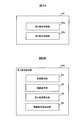
- FIG. 1 is a block diagram showing a configuration of an image restoration apparatus according to an embodiment of the present invention.
- 2A is a block diagram showing the configuration of the image restoration processing unit in FIG. 1
- FIG. 2B is a block diagram showing the configuration of the first restoration processing unit in FIG. 2A.
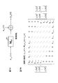
- Diagram for explaining the process of image degradation Block diagram showing the system configuration of the state space model of the inventive method.
- FIG. 5A is a figure which shows the state process of a state space model
- FIG. 5B is an example of a process target block and its time change
- FIG. 5C shows a specific example of the state equation.
- FIG. 7A is a figure which shows the observation process of a state space model
- FIG. 7B is a figure which shows the specific example of an observation equation
- FIG. 8A is a figure which shows the definition of the conventional observation equation
- FIG. 8B is a state quantity which affects an observation amount.
- Graphic showing range visually is a figure for demonstrating the structure of the observation equation of an invention method
- FIG. 9A is a figure which shows the definition of the observation equation of an invention method
- FIG. 9A is a figure which shows the definition of the observation equation of an invention method
- FIG. 9B shows the range of the state quantity which affects an observation amount visually.
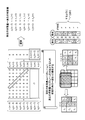
- Illustration Diagram for explaining how to assign the coefficients that make up the observed transition matrix
- the flowchart which shows the process sequence which performs the algorithm of FIG.
- Explanatory diagram summarizing the invention method visually Diagram for explaining simulation conditions Illustration for explaining the original image "Cameraman”
- the figure which shows the simulation result (visual evaluation) for original picture “cameraman” The figure which expanded the peripheral area of the circle of the broken line in FIG.
- FIG. 1 is a block diagram showing a configuration of an image restoration apparatus according to an embodiment of the present invention.
- a suitable image restoration apparatus to which the image restoration method of the present invention is applied will be described by taking a general-purpose image restoration apparatus that can handle various applications as an example.
- the image restoration apparatus 100 shown in FIG. 1 is configured by a computer, and is roughly divided into an image input apparatus 110, an input interface unit 120, an operation unit 130, an internal interface unit 140, a storage unit 150, an image restoration processing unit 160, and an output.
- An interface unit 170 and an image output device 180 are included.
- the image input device 110 is an input device for inputting image data (degraded image) to be restored to a computer as digital data.
- the input image may be a still image or a moving image.
- a camera 112 for example, a camera 112, a scanner 114, a recording medium 116, a modem 118, or the like can be used.
- the camera 112 means all devices having an imaging function.
- a digital camera digital still camera and digital video camera
- a mobile phone equipped with a camera function a security camera (surveillance camera), an image diagnosis Medical equipment (endoscope, X-ray, echo, CT, MRI, etc.), etc.
- the scanner 114 is one of typical image input devices, and includes a film scanner that exclusively reads from files such as negatives and positives.
- the recording medium 116 broadly means a recording medium capable of recording image data.
- a magnetic disk HDD, FD, etc.
- an optical disk CD, DVD, BD, etc.
- a magneto-optical disk MO
- the modem 118 is a device for connecting to an external communication network (for example, a telephone line, a LAN, the Internet, etc.).
- an external communication network for example, a telephone line, a LAN, the Internet, etc.
- the type of the image input device 110 may be appropriately selected according to the application of the image restoration device 100.
- the input interface unit 120 performs input processing such as converting image data provided from the image input device 110 into a data format that can be processed by a computer.
- the input interface unit 120 is provided separately and independently according to the type of the image input device 110.
- the input interface unit 120 of the recording medium 116 is also called a drive, and various types of drives can be used depending on the type of the recording medium 116.
- the drive is a device that reads and writes recording media.
- the input interface unit 120 and the output interface unit 170 are usually integrated.
- the modem 118 can function as both the image input device 110 and the image output device 180. Therefore, the input interface unit 120 and the output interface unit 170 are usually integrated with respect to the modem 118 as well.
- the input interface unit 120 may be a built-in card (board) stored inside the computer main body, or may be an externally installed device connected via the internal interface unit 140.
- the corresponding input interface unit 120 includes a sampling unit and an A / D conversion unit (both not shown).
- the sampling unit samples the input analog signal at a predetermined sampling frequency and outputs the sampled analog signal to the A / D conversion unit.
- the sampling frequency can be changed according to the type of restoration process target (information source).
- the A / D converter performs A / D conversion processing on the amplitude value of the sampled signal with a predetermined resolution.
- the operation unit 130 is typically a keyboard, a mouse, a touch panel, or the like, but a voice recognition device or the like may be used. The user can operate the computer using the operation unit 130 while confirming on a display 182 to be described later, for example.
- the operation unit 130 includes a parameter setting unit 132, an area specifying unit 134, and a restoration mode specifying unit 136.
- the parameter setting unit 132 sets various parameter values necessary for image restoration processing according to the present embodiment, which will be described in detail later, by a user input operation.
- the area designating unit 134 designates an area (a specific range of an image) to be subjected to image restoration processing for the input image by a user input operation.
- the restoration mode designating unit 136 designates a restoration mode to be described later by a user input operation.
- the internal interface unit 140 is inside the computer main body and has a function of connecting the input interface unit 120, the operation unit 130, the storage unit 150, the image restoration processing unit 160, and the output interface unit 170 to each other. Various signals are exchanged inside the computer via the internal interface unit 140.
- the storage unit 150 includes a main storage device 152 and an auxiliary storage device 154.
- the main storage device 152 is an element constituting the main body of the computer, and mainly stores programs and data.
- the auxiliary storage device 154 is a storage device that compensates for the lack of capacity of the main storage device 152.
- the auxiliary storage device 154 is typically a hard disk (HD), but may be a portable device such as a CD-ROM, DVD, SSD (Solid State Drive), flash memory, or the like. A combination of these may be used.
- the program (image restoration algorithm) for executing the image restoration process in the present embodiment may be stored in advance in the storage unit 150 (the main storage device 152 or the auxiliary storage device 154), or both the interface units from the recording medium 116. It may be installed in the storage unit 150 via 120 and 140, or may be downloaded to the storage unit 150 from the outside via the modem 118 and both interface units 120 and 140.
- image restoration processing is performed on the captured image data, and the restored image data is retrieved from the image output device 180.
- a storage area for storing image data, a storage area temporarily necessary for data processing (called a work area or a work memory), and a storage area for storing image data to be output is necessary. These storage areas are allocated on the main storage device 152 or the auxiliary storage device 154.
- image data after restoration processing is output to a display 182 to be described later.
- the display memory 156 is shown separately on the drawing.
- the image restoration processing unit 160 is a characteristic component of the present invention, and executes a built-in image restoration algorithm described later.
- a state space model state equation and observation equation
- the image restoration is realized by executing the Kalman filter, whereas the image restoration method of the present invention (hereinafter referred to as “invention technique”) uses a new prediction method composed of a state equation and an observation equation. Restore is realized.
- the state equation is clear image information (original image). Information)
- image restoration is realized. Yes.
- the image to be restored may be a still image or a moving image.
- the image output device 180 is an output device for taking out image data (restored image) restored by the computer (image restoration processing unit 160) to the outside in a predetermined output form.
- a display 182, a printer 184, a recording medium 186, a modem 188, or the like can be used as the image output device 180.
- the recording medium 186 and the modem 188 may be shared with the recording medium 116 and the modem 118 as the image input device 110, respectively.
- the type of the image output device 180 may be appropriately selected according to the application of the image restoration device 100.
- the output interface unit 170 performs output processing such as converting image data (restored image) restored by the computer (image restoration processing unit 160) into a data format that can be output to the image output device 180.
- the output interface unit 170 is provided separately and independently according to the type of the image output device 180.
- the input interface unit 120 and the output interface unit 170 are usually integrated.
- the output interface unit 170 may be a built-in card (board) stored inside the computer main body, or an externally installed device connected via the internal interface unit 140. May be.
- FIG. 2A is a block diagram showing the configuration of the image restoration processing unit 160 in FIG. 1
- FIG. 2B is a block diagram showing the configuration of the first restoration processing unit 160a in FIG. 2A.
- the image restoration processing unit 160 includes a first restoration processing unit 160a and a second restoration processing unit 160b.
- the first restoration processing unit 160a performs the image restoration method of the present invention.
- the second restoration processing unit 160b performs an image restoration method other than the image restoration method of the present invention, for example, a conventional image restoration method such as an image restoration method using a Wiener filter or an image restoration method using a Kalman filter.
- a conventional image restoration method such as an image restoration method using a Wiener filter or an image restoration method using a Kalman filter.
- image restoration processing using the first restoration processing unit 160a and the second restoration processing unit 160b can be performed.
- an image restoration method using a Wiener filter hereinafter referred to as “conventional method” is taken as an example.
- the first restoration processing unit 160a includes an initial setting unit 162, a correlation calculation unit 164, a weighting factor calculation unit 166, and an optimum estimated value calculation unit 168.
- the first restoration processing unit 160a executes a built-in image restoration algorithm (invention technique) in cooperation with each of the units 162 to 168, so that a clear image (original image) is obtained only from the captured image data (degraded image). ).
- the initial setting unit 162 performs initial setting of the image restoration algorithm of the inventive method
- the correlation calculation unit 164 performs correlation calculation of the estimation error of the original image (desired information, clear image)
- the weight coefficient calculation unit 166 calculates a weighting coefficient necessary for calculating the optimum estimated value of the original image (desired information)
- the optimum estimated value calculating unit 168 calculates the optimum estimated value of the original image (desired information).
- a deteriorated image is generally obtained by a model obtained by adding noise to a convolution of an original image and a blurred point spread function (PSF: Point Spread Function). That is, a degraded image g (x, y) obtained by an imaging system (an apparatus that captures an object, a system that generates an image, etc.) is f (n, m) representing the original image representing the object, and the point spread of the blur is increased.
- the function is represented by h (x, y) and the noise is represented by n (x, y), it is represented by the following equation (1).
- the blurred point spread function h (x, y) represents the characteristics of the imaging system including imaging conditions.
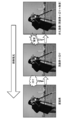
- FIG. 3 is a diagram for explaining a process of image degradation.
- the deteriorated image shown at the right end of FIG. Blur is caused by a pixel affecting its surrounding pixels, but noise occurs regardless of the pixel.
- blur is caused by camera shake or defocus, and noise is unavoidably caused by dark current or thermal noise.
- restoration of a degraded image is nothing but removing blur and noise from the degraded image.
- a new state space model (state equation and observation equation) is constructed so as not to use the concept of the AR system. That is, the state equation is configured using only clear image information (original image information), and the observation equation is configured using degraded image information, clear image information (original image information), blur information, and noise. .
- a new state space model (state equation and observation equation) is constructed, and this new state space model is expressed by the following equation (2).
- the vector x p1 (n) is a state vector (original image information)
- the matrix ⁇ p1 is a state transition matrix
- the vector ⁇ p1 (n) is a drive source.
- the vector y p1 (n) is an observation vector (observation image information and degraded image information)
- the matrix M p1 is an observation transition matrix
- the vector ⁇ p1 (n) is an observation noise.
- “N” is the time n of the apparatus.
- Time n represents the processing order (nth) of the processing target block including a plurality of peripheral pixels including the target pixel.
- invention technique 1 one specific technique (hereinafter referred to as “invention technique 1”) is presented as an invention technique.
- the subscript “p1” indicates that the invention method 1 is concerned.
- FIG. 4 is a block diagram showing the system configuration in this state space model.
- this state space model is composed of a state process and an observation process.
- a state process is described by a state equation, and an observation process is described by an observation equation.
- “201” is a state vector x p1 (n) at time n
- “202” is a state vector x p1 (n + 1) at time n + 1
- “203” is an observation vector y p1 (n) at time n
- “ 204 ” is the observed noise vector ⁇ p1 (n) at time n
- “ 205 ” is the drive source vector ⁇ p1 (n + 1) at time n + 1
- “ 206 ” is the state transition matrix ⁇ p1
- “ 207 ” is the observed transition matrix M p1.
- the state equation in equation (2) describes the system to be observed with a state space model, and is an internal state, that is, a state variable (here, state vectors x p1 (n), x p1 (n + 1)) with respect to time. It shows the generation process.
- the observation equation in equation (2) describes the process of observation through some kind of observation device, and the observation result (here, the observation vector y p1 (n)) is the observed quantity, that is, the input (here, It shows how it is generated depending on the state vector x p1 (n)).
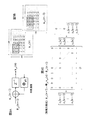
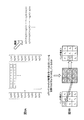
- FIG. 5 is a diagram for explaining a specific example of the formulation of the state equation of the inventive method.
- FIG. 5A is a diagram showing a state process of the state space model
- FIG. 5B is a block to be processed and its time.
- FIG. 5C is a diagram illustrating an example of the change
- FIG. 5C is a diagram illustrating a specific example of the state equation.
- the degraded image restoration process is performed using not only the processing target pixel but also the surrounding pixels. That is, an area of K ⁇ K (where J> K) (hereinafter referred to as “region of interest”) around a processing target pixel of a J ⁇ J size image is set as a processing target block, and this processing is performed. Image restoration processing is performed using pixel information in the target block.
- the attention area means a range in which processing is performed using K ⁇ K pixels in image restoration.
- a processing target pixel of an image having a size of 256 ⁇ 256 is centered, and a surrounding region of 3 ⁇ 3 is a processing target block. It becomes. In the drawing, the block to be processed is shaded.
- the image restoration process is performed using pixel information in the 3 ⁇ 3 attention area.
- FIG. 5B assuming that some pixels of an image having a size of 256 ⁇ 256 are numbered 1 to 36, this corresponds to the state vector x p1 (n) at time n.
- the processing target block includes 9 pixels of 3 ⁇ 3 with numbers 1, 2, 3, 7, 8, 9, 13, 14, and 15, and the state vector x p1 (n + 1) at the next time n + 1.
- the processing target block corresponding to is composed of 9 pixels of 3 ⁇ 3 with numbers 7, 8, 9, 13, 14, 15, 19, 20, and 21.
- the state equation in the equation (2) is defined by the following equation (3) also shown in FIG. 5C.
- the state vector x p1 (n) is nine pieces of pixel information x 1 (n), x 2 (n), and x 3 (x 3 (n) included in a 3 ⁇ 3 processing target block as a state quantity including original image information.
- the state transition matrix ⁇ p1 is a 9 ⁇ 9 order matrix defined by the equation (3)
- the drive source vector ⁇ p1 (n) is a 9 ⁇ 1 order matrix similarly defined by the equation (3). Is a vector.
- FIG. 6 is a diagram for explaining the configuration of the state equation represented by Expression (3).
- the state equation representing the relationship between x p1 (n) and x p1 (n + 1) is x p1 (n) composed of a clear image, ⁇ p1 composed of 0 and 1, and a clear image that is a colored signal.
- FIG. 7 is a diagram for explaining a specific example of the formulation of the observation equation of the invention technique.
- FIG. 7A is a diagram showing the observation process of the state space model
- FIG. 7B is a specific example of the observation equation.
- the observation equation in the equation (2) is defined by the following equation (4) also shown in FIG. 7B.
- the observation vector y p1 (n) is nine pieces of pixel information y 1 (n), y 2 (n), y 3 (y) included in the 3 ⁇ 3 processing target block as an observation amount including degraded image information.
- the observed transition matrix M p1 is a 9 ⁇ 9 order matrix defined by the equation (4), and corresponds to the blur point spread function (PSF) in the image degradation model.
- PSF blur point spread function
- the observation noise vector ⁇ p1 (n) is the observation noise ⁇ 1 (n), ⁇ 2 (n), ⁇ 3 (n), ⁇ corresponding to nine pixels included in the 3 ⁇ 3 processing target block. 4 (n), ⁇ 5 (n), ⁇ 6 (n), ⁇ 7 (n), ⁇ 8 (n), and ⁇ 9 (n) are 9 ⁇ 1 order vectors.
- FIG. 8 is a diagram for explaining the configuration (general example) of a conventional general observation equation
- FIG. 9 is a diagram for explaining the configuration of the observation equation represented by equation (4).
- FIG. 8A is a diagram showing the definition of a conventional general observation equation
- FIG. 8B is a diagram visually showing a range of state quantities that affect the observed quantity
- FIG. 9A is a diagram showing the definition of the observation equation of the inventive method
- FIG. 9B is a diagram visually showing the range of state quantities that affect the observed quantity.
- the observation noise vector ⁇ p1 (n) is omitted for convenience.
- FIG. 8A Deterioration due to blur in an image means that a certain pixel deteriorates under the influence of surrounding pixels as described above. Therefore, conventionally, an observation equation is generally defined as shown in FIG. 8A.
- the blur is caused by being affected by all surrounding pixels. That is, each pixel in the processing target block is affected by all the pixels in the processing target block.
- FIG. 9A shows some expressions (expressions relating to y 1 (n), y 2 (n)) obtained by expanding the observation equation.
- the observation amount y i of interest is shown in the left processing target block, and each state influencing the right processing target block is shown.
- the location of the amount x i, h r to be multiplied by the quantity of state x i shows s only.
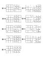
- the observation amount y 1 is affected by five state quantities x 1 to x 5 as shown in FIG. 11A, and the observation amount y 2 is shown in FIG. 11B.
- the observation quantity y 4 is affected by the eight state quantities x 1 to x 8 , and the observation quantity y 5 becomes all nine state quantities x as shown in FIG. 11E.
- the observation amount y 6 is affected by eight state quantities x 2 to x 9 as shown in FIG. 11F.
- the observation amount y 7 is affected by seven state quantities x 3 to x 9 , and the observation quantity y 8 is changed into six state quantities x 4 as shown in FIG. 11H.
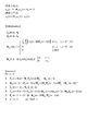
- FIG. 12 is a diagram showing an example of the algorithm of the inventive method. This algorithm can be applied not only to still images but also to moving images, regardless of the type of image.
- the algorithm of the invention method 1 is roughly divided into an initialization process and an iteration process, and the iterative process is a new state space model (state equation and observation equation). It is composed based on. In the iteration process, steps 1 to 6 are repeated sequentially.
- FIG. 13 is a flowchart showing a processing procedure for executing the algorithm of FIG.
- the initial setting unit 162 performs initial setting (S1000). Specifically, in the initial setting unit 162, an initial value x p1 of an optimum estimated value of a state vector, that is, a desired signal (original image signal) vector that is a state quantity (hereinafter referred to as an “optimum estimated value vector of a desired signal”). (0
- the state transition matrix ⁇ p1 and the observed transition matrix M p1 are set as shown in Expression (3) and Expression (4), respectively.
- the initial value of the counter at time n is set to “0”.
- the i-th element of the vector a (n) is expressed as a (n) [i]
- the i-th row and j-th column element of the matrix A (n) is A (n). It shall be written as [i, j].
- the optimum estimated value vector x p1 of the desired signal is expressed as a hat x p1 .
- the vector 0 K is a K-dimensional zero vector
- the matrix I K is a K-th order unit matrix.
- K is the dimension of the region of interest having a size of K ⁇ K.
- K 3
- K 2 ⁇ K 6
- E [ ⁇ p1 (n), ⁇ p1 T (n)] is an autocorrelation matrix of the drive source vector ⁇ p1 (n).
- E [ ⁇ p1 (n) ⁇ p1 T (n)] [i, j] is an autocorrelation matrix of the observed noise vector ⁇ p1 , here it is equal to ⁇ 2 ⁇ [i, j] and is assumed to be known. ing. “Known” here means obtained and given by another arbitrary method (algorithm). If the observed noise vector ⁇ p1 (n) is white noise and is zero average, ⁇ 2 ⁇ is given by a variance of a predetermined number of samples.
- the correlation calculation unit 164 calculates an error covariance matrix of n ⁇ (n + 1), that is, a correlation value (matrix) (hereinafter also referred to as “correlation matrix”) of an estimation error of n ⁇ (n + 1) (S1100). ). Specifically, the correlation calculation unit 164 calculates a correlation matrix P p1 (n + 1
- This step S1100 corresponds to procedure 1 of the iterative process of FIG.
- the weighting factor calculation unit 166 calculates a weighting factor (matrix) (S1200). Specifically, the weighting factor calculation unit 166 multiplies the estimation error of the observation signal vector that is an observation amount (hereinafter referred to as “estimation error vector of the observation signal”) by a weighting factor (matrix), and uses the information up to time n. The addition of the optimum estimated value vector x p1 (n + 1
- This calculation is performed by calculating the correlation matrix P p1 (n + 1
- This step S1200 corresponds to procedure 2 of the iterative process of FIG.
- the optimum estimated value calculation unit 168 calculates the optimum estimated value (vector) of the state quantity (desired signal) of n ⁇ (n + 1) (S1300). Specifically, the optimum estimated value calculation unit 168 calculates an optimum estimated value vector x p1 (n + 1
- This step S1300 corresponds to procedure 3 of the iterative process of FIG.
- the optimum estimated value calculation unit 168 calculates the optimum estimated value (vector) of the state quantity (desired signal) from (n + 1) ⁇ (n + 1) (S1400). Specifically, the optimum estimated value calculation unit 168 calculates an optimum estimated value vector x p1 (n + 1
- This calculation includes an optimal estimated value vector x p1 (n + 1
- This step S1400 corresponds to procedure 4 of the iterative process of FIG.
- step S1500 it is determined whether or not to end the process. This determination is made, for example, by determining whether the time n has reached a predetermined number N of samples. As a result of this determination, when the time n has not reached the predetermined number of samples N (S1500: NO), the process proceeds to step S1600, and when the time n has reached the predetermined number of samples N (S1500: YES), The process proceeds to step S1800.
- the criterion for determination is not limited to the above example. For example, when processing is performed in real time, the processing may be terminated when there are no more samples even if the time n has not reached the predetermined number of samples N.
- step S1600 the correlation calculation unit 164 calculates an error covariance matrix of (n + 1) ⁇ (n + 1), that is, a correlation value (matrix) of an estimation error of (n + 1) ⁇ (n + 1). Specifically, the correlation calculation unit 164 calculates a correlation matrix P p1 (n + 1
- This calculation is performed by calculating the correlation matrix P p1 (n + 1
- This step S1600 corresponds to procedure 5 of the iterative process of FIG.
- step S1800 the calculation result of this algorithm is temporarily stored as an output value.
- n + 1) of the desired signal calculated in step S1400 is temporarily stored in the image restoration processing unit 160 or the storage unit 150 as an output value of this algorithm.
- FIG. 14 is an explanatory diagram visually summarizing the invention method. As described above, in the inventive method, since a new state space model (state equation and observation equation) is configured, it is possible to perform image restoration processing by one-step processing. This is one of the major features of the present invention.
- the two-stage process (after determining the AR order and estimating the AR coefficient in Step 1, using the estimated AR coefficient in Step 2, the state is determined.
- Image restoration is realized by a spatial model (a state equation and an observation equation are formed and a Kalman filter is executed). Therefore, it is easily expected that the image restoration capability by the Kalman filter in step 2 is greatly influenced by the determination of the AR order in step 1 and the estimation accuracy of the AR coefficient.
- a new state space model state equation and observation equation) that does not require the concept of the AR system is constructed, and a high-performance image restoration is performed by a new one-step prediction method using the state space model. Is realized.
- the number of processing steps can be reduced by one step, so that the amount of calculation can be reduced, and consequently the circuit scale can be reduced and the memory capacity can be reduced.
- the determination of the order of the AR coefficient necessary for estimating the AR coefficient in Step 1 becomes a big problem.
- the order of the AR coefficient depends on the state quantity, it is difficult to theoretically accurately determine the order of the AR coefficient unless the state quantity is known. This means that the state quantity must be known, and real-time processing becomes difficult.
- the order of the AR coefficient that is not accurate is used, it is difficult to estimate the AR coefficient accurately. Therefore, this is a major factor for reducing the image restoration capability of the conventional image restoration method using the Kalman filter. Even if the AR order and the AR coefficient can be estimated in real time by some technique, an increase in the calculation amount is unavoidable due to an increase in the number of processing steps. On the other hand, since the inventive method does not require the concept of the AR system, such a problem does not occur.
- the state quantity is modeled by expressing it using the AR system.
- the conventional image restoration method using the Kalman filter can be applied only to state quantities that can be modeled by the AR system. That is, the conventional image restoration method using the Kalman filter cannot be applied to state quantities that are difficult to model in the AR system.
- the inventive method does not require the concept of the AR system, there is no such restriction regarding the application target.
- the Kalman filter theory is applied on the assumption that the driving source of the state equation is a white signal and the state quantity and the observation noise are uncorrelated.
- the algorithm of the inventive method can be executed by a special configuration of the state equation and the observation equation. This means that the inventive method can be implemented without considering general application conditions of Kalman filter theory. That is, it can be said that the invention method has a wider application range than the Kalman filter theory.
- the inventive method that does not require the concept of the AR system is a scene where re-taking of images is not allowed, for example, instantaneous restoration of images such as the heart and lungs in the medical field, restoration of old documents degraded due to dirt, It can also contribute to character / object recognition.
- the inventor performed a simulation to verify the effect of the present invention (effectiveness of the inventive method). Specifically, in order to evaluate the image restoration ability of the inventive method 1, (1) visual evaluation, (2) objective evaluation, and (3) subjective evaluation were performed.
- the visual evaluation is an evaluation in which an original image and a restored image are compared visually.
- Objective evaluation is numerical evaluation.
- Subjective evaluation is an interview survey. Hereinafter, these will be described in order.
- FIG. 15 is a diagram for explaining the simulation conditions.
- the image “cameraman” has a strong steadiness because the dispersion of the image is not changed in the sky portion, and is non-stationary because the dispersion of the image is changed in the head portion of the person. It can be said that the nature is strong.
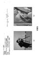
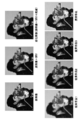
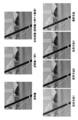
- FIG. 17 is a diagram showing a simulation result (visual evaluation) for the original image “cameraman”, and FIG. 18 is an enlarged view of a peripheral area of a broken-line circle in FIG.
- the conventional technique 1 has almost no blur.
- the blur is removed more than in the conventional method 1, but the blur still remains as compared with the original image.
- the conventional method 3 is a restored image different from the original image, although the blur is removed and the image is clearer than the conventional methods 1 and 2.
- the conventional method 3 is darker as a whole than the original image, and the sky portion is deteriorated more than the deteriorated image.
- the inventive method faithfully restores the original image as compared with the conventional methods 1, 2, and 3, as shown in FIG. That is, the effectiveness of the inventive method can also be confirmed in the enlarged image of FIG.
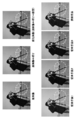
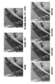
- FIG. 19 is a diagram showing a simulation result (visual evaluation) for the original image “cameraman”, and FIG. 20 is an enlarged view of a peripheral area of a broken-line circle in FIG.
- the conventional method 1 does not remove the blur at all.
- the blur is removed from the conventional method 1, but the original image is not restored.
- the conventional method 3 seems to have removed the blur as compared with the conventional methods 1 and 2, but the entire image is rough, and it can be confirmed that it is a restored image far from the original image.
- the inventive method restores the original image more faithfully than the conventional methods 1, 2, and 3, as shown in FIG. That is, the effectiveness of the inventive method can be confirmed also in the enlarged image of FIG.
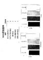
- FIG. 21 is a diagram showing a simulation result (visual evaluation) for the original image “Lena”, and FIG. 22 is an enlarged view of a peripheral area of a broken-line circle in FIG.
- the conventional method 1 As well shown in FIG. 22, in the conventional method 1, the blur is hardly removed, and the restored image is generally whiter than the original image (the luminance is high).
- the conventional method 2 has the blur removed as compared with the conventional method 1, but the blur has not been removed up to the original image.
- the conventional method 3 is clearer than the conventional methods 1 and 2 and appears to be clear, but has deteriorated more than the deteriorated image, and is an image far from the original image. . This point is particularly noticeable when paying attention to the skin area.
- FIG. 23 is a diagram illustrating a simulation result (objective evaluation) for an original image.
- the image restoration capability was evaluated using SNR out [dB] represented by the following equation (11) also shown in FIG.
- SNR is the ratio of noise to signal, and it can be said that the larger the numerical value, the less the deterioration (such as blur and noise) and the better the image.
- the invention method has a larger SNR out value than the conventional methods 1, 2, and 3 for both the “cameraman” and “Lena” images.
- the inventive method has higher image restoration capability than the conventional methods 1, 2, and 3 in terms of objective evaluation.
- FIG. 24 is a diagram illustrating a simulation result (subjective evaluation) for an original image.
- a subjective evaluation was conducted by interview survey.
- the performance evaluation of the image restoration was performed by an interview survey using a 5-step MOS (average opinion value) based on ACR (absolute category evaluation).
- MOS evaluation criteria are as shown in FIG. Fifty listeners evaluated images obtained by image restoration (see FIGS. 17 to 22). Each listener determines an evaluation value “1” to “5”. The evaluation value “5” is the best.
- the MOS method has a higher evaluation than the conventional methods 1, 2, and 3 for both the “cameraman” and “Lena” images.
- the inventive method has higher image restoration capability than the conventional methods 1, 2, and 3 in terms of subjective evaluation.
- the image restoration method of the present invention exhibits higher image restoration ability than the conventional technique.
- the image restoration method of the present invention has significantly higher restoration accuracy than the conventional method in the edge portion where the non-stationarity is strong.
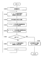
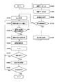
- the flowchart shown in FIG. 25 is stored as a control program in the storage unit 150 (the main storage device 152 or the auxiliary storage device 154), and is executed by a CPU (not shown).
- step S2000 image data (degraded image) to be restored is captured from the image input device 110 and stored in a predetermined storage area of the storage unit 150 (the main storage device 152 or the auxiliary storage device 154).
- step S2050 the image data captured in step S2000 is written in the display memory 156 and displayed on the display 182.
- step S2100 the area specifying unit 134 of the operation unit 130 performs area specifying processing. Specifically, when an area to be subjected to image restoration processing (a specific range of an image) is specified in the image displayed on the display 182 in step S2050 by the user's input operation, the specified area is displayed. Generate data. The area is specified by, for example, a pointer on the screen. If the area is not designated by the user, the entire displayed image is treated as designated.
- image restoration processing a specific range of an image
- step S2150 it is determined whether or not to perform enlargement processing. This determination is made based on the designated area data generated in step S2100, for example. Specifically, when the designated area is smaller than the entire displayed image, it is determined that the enlargement process is performed. As a result of this determination, when the enlargement process is performed (S2150: YES), the process proceeds to step S2200, and when the enlargement process is not performed (S2150: NO), the process immediately proceeds to step S2250.
- step S2200 the area designated in step S2100 is enlarged. Specifically, for example, the enlargement process is performed so that the designated area has a size corresponding to the entire displayed image.
- the result of the enlargement process is written in the working memory of the storage unit 150 (the main storage device 152 or the auxiliary storage device 154). Even when the enlargement process is not performed, the image data is written in the working memory.
- step S2250 the processing target block at time n (eg, 3 ⁇ 3 size) is selected.
- step S2300 it is determined whether or not an abrupt change region of the image is detected for the processing target block selected in step S2250.
- the sudden change region of the image corresponds to, for example, an edge portion of the image.
- pixel data is processed on the processing target block (3 ⁇ 3 size) selected in step S2250.
- step S2400 it is detected whether there is a sudden change point of pixel data.
- An example of a specific detection method is as follows.
- ⁇ it is determined that there is no abrupt pixel data change point.
- step S2350 image restoration processing by the inventive method is performed on the processing target block selected in step S2250.
- the image restoration process according to the invention technique can be performed with high accuracy even when there is a sudden change point of pixel data, that is, when an edge portion or the like is included.
- An example of the detailed procedure of the image restoration process according to the inventive method is as described with reference to the flowchart of FIG.
- step S2400 an image restoration process using an image restoration technique other than the inventive technique is performed on the processing target block selected in step S2250.
- image restoration method any image restoration method including an image restoration method using a Wiener filter, an image restoration method using a projection filter, an image restoration method using a Kalman filter, and the like can be used. This is because when there is no abrupt change point of pixel data, that is, when an edge portion or the like is not included, restoration processing can be performed with high accuracy by other image restoration methods.
- step S2450 the restoration processing result in step S2350 or the restoration processing result in step S2400 is sequentially stored in the working memory of the storage unit 150 (the main storage device 152 or the auxiliary storage device 154).
- step S2500 the value of the counter at time n is incremented by one.
- step S2550 it is determined whether or not the image restoration process for one page has been completed. This determination is made based on the value of the counter at time n. As a result of this determination, if the image restoration process for one page is completed (S2550: YES), the process proceeds to step S2600, and if the image restoration process for one page is not completed (S2550: NO), step The process returns to S2250.
- step S2600 since the image restoration processing for one page is completed, the display memory 156 is updated. In other words, the display memory 156 is updated when the image restoration process for one page is completed.
- step S2650 it is determined whether the image restoration process has been completed for all pages of the image data captured in step S2000. As a result of this determination, if the image restoration process for all pages has not been completed (S2650: NO), the process returns to step S2250, and if the image restoration process for all pages has been completed (S2650: YES), A series of processing ends.
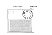
- FIG. 27 is a diagram for explaining an example of implementation of the restoration mode.
- the observation transition matrix M p1 is a 9 ⁇ 9 order matrix defined by the equation (4), and corresponds to the blur point spread function (PSF) in the image degradation model.
- the user can arbitrarily specify the restoration mode via the restoration mode designation unit 136 of the operation unit 130. For example, in the example of FIG.
- an appropriate observation transition matrix M p1 suitable for each shooting mode is set in advance for each shooting mode such as a night view mode or a sport mode that is often set for a digital camera or the like. . Therefore, the user can use the optimum restoration mode by switching the photographing mode. Note that the restoration mode (values of the elements h r and s of the observed transition matrix M p1 ) itself can be readjusted automatically or manually.
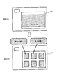
- FIG. 28 is a diagram for explaining another example of implementation of the restoration mode.
- a new state space model (state equation and observation equation) that does not require the concept of the AR system is constructed, and image restoration is performed by a new prediction method of one-stage processing.
- image restoration is performed by a new prediction method of one-stage processing.
- it has a simple configuration that does not require the steps of determining the AR order and estimating the AR coefficient, and has a utility that can effectively perform restoration processing even for a natural image with strong non-stationarity,
- the image restoration capability can be improved as compared with the conventional method.
- the present invention can be widely applied to scenes in which retaking of images is not permitted.
- the type of image is not limited and may be a still image or a moving image.
- the inventive method to a degraded image including an enlarged image, it is possible to remove blur and noise from the degraded image and provide a clear image not only in the crime prevention field but also in a surveillance camera or the like.
- the present invention can also be applied to the case where accident determination or instrument failure diagnosis is performed based on a photographed image.
- the image restoration technology installed in these products is a technology for preventing blur and noise such as face recognition and filters, and does not assume a scene where re-shooting is not allowed. Therefore, by applying the inventive method to these products, instantaneous image restoration that does not allow re-taking is possible.
- one of the most effective means for investigating health is diagnostic imaging such as endoscopes, X-rays, echoes, CT, and MRI.
- diagnostic imaging such as endoscopes, X-rays, echoes, CT, and MRI.
- the health diagnosis is performed from information including blur and noise by the operation of the lungs and the heart.
- the invention method is also effective in the case of such a front / rear camera of an automobile that requires image restoration processing in real time.
- the image restoration apparatus and the image restoration method according to the present invention are useful as a simple and practical image restoration apparatus and an image restoration method capable of improving the image restoration capability.
Landscapes
- Physics & Mathematics (AREA)
- General Physics & Mathematics (AREA)
- Engineering & Computer Science (AREA)
- Theoretical Computer Science (AREA)
- Image Processing (AREA)
Abstract
画像復元性能を向上できるシンプルで実用的な画像復元装置。画像復元装置100は、第1復元処理部160aを有し、原画像情報に不必要な情報が混在した劣化画像情報から原画像情報を推定する。相関演算部164は、時刻nのみの劣化画像情報に対して、時刻n又は時刻n+1までの情報により原画像情報を含む時刻n+1でのシステムの状態量を推定した場合の推定誤差の相関値を算出する。重み係数算出部166は、時刻nのみの劣化画像情報に対して、前記相関値を用いて、時刻n+1までの情報による時刻n+1での状態量の最適推定値と、時刻nまでの情報による時刻n+1での状態量の最適推定値と、劣化画像情報を含む観測量の推定誤差との関係を規定するための重み係数を算出する。最適推定値算出部168は、時刻nのみの劣化画像情報に対して、前記重み係数を用いて、時刻n+1までの情報による時刻n+1での状態量の最適推定値を算出する。
Description
本発明は、画像復元装置および画像復元方法に関する。
近年、画像工学の分野において、劣化した画像から原画像を復元する技術の研究開発が多くなされている。すなわち、原画像(所望情報、クリアな画像)に不必要な情報(ぼけと雑音)が混在した劣化画像(受信情報)から不必要な情報(ぼけと雑音)を取り除き、原画像(所望情報)のみを抽出することは、画像復元の分野において必要不可欠な技術であり、近年盛んに研究開発が行われている。例えば、デジタルカメラ(デジタルスチルカメラおよびデジタルビデオカメラの総称)や携帯電話などで撮影された画像は、手ぶれや焦点ずれなどに起因する「ぼけ」と、暗電流や熱雑音などに起因するガウス性またはインパルス性の「雑音」との影響から、実物と比較して画質が劣化することは避けられない。「画像復元」とは、このように劣化した画像からできるだけ原画像に近い画像を復元することである。
現在一般に市場で普及している画像復元技術の多くは、例えば、手ぶれ補正や顔認識、色補正、様々なフィルタなどを用いて、予めぼけと雑音の影響を軽減させる予防的な技術が主流となっている。この結果、近年、特にデジタルカメラの分野では、デジタルカメラの多機能化・高性能化により鮮明な画像が気軽に手に入れられるようになってきている。
しかし、これらの予防的な技術は、何度も画像を撮り直せる状況下では問題ないが、古文書などの既に劣化している画像や、スポーツや医療などの分野における瞬間的に変化する画像など、撮り直しが許されない画像に対する復元は、いまだ困難な問題である。ここで、スポーツと医療の分野における瞬間的に変化する画像は、例えば、選手の瞬間的な動作や、肺や心臓などの臓器の瞬間的な様子などである。したがって、今日、特に、撮り直しが許されない状況下における画像復元の重要性が高まってきている。
撮り直しが許されない状況下における従来の画像復元技術として、ウィナーフィルタ(Wiener Filter)を用いた画像復元手法が広く知られている(非特許文献1、非特許文献2)。この手法は、フィルタを通して得られる復元画像と原画像との平均2乗誤差を最小にするフィルタであって、最小2乗フィルタとも呼ばれている。この手法は、周波数領域で処理を行うため、確率過程の定常性と半無限長の画像のサイズとを前提にした画像復元手法である。
また、他の画像復元技術として、射影フィルタを用いた画像復元手法も知られている(非特許文献3、非特許文献4)。射影フィルタは、原画像と復元画像との近さを直接原画像の空間で評価しており、復元画像の雑音の画像成分が個々の原画像の最良近似、つまり、個々の原画像の正射影となるものの中で、復元画像の雑音成分の2乗平均を最小にするものである。また、この性質から、射影フィルタは、出現頻度に無関係に、最良近似画像を復元する手法である。
また、さらに他の画像復元技術として、カルマンフィルタ(Kalman Filter)を用いた画像復元手法も知られている(非特許文献5、非特許文献6)。この手法は、まずステップ1で、劣化画像に対してAR(Auto Regressive:自己回帰)システムのパラメータ(以下「AR係数」という)を推定した後、ステップ2で、ステップ1で推定したAR係数を用いて状態空間モデル(状態方程式と観測方程式)を構成し、これにカルマンフィルタ理論(カルマンフィルタアルゴリズム)を適用することによって、高性能な画像復元を実現している。
西宮亮平、外1名、「複数のウィーナーフィルタによる画像復元」(Image Restoration by Using Multiple Wiener Filters)、電子情報通信学会論文誌、A、Vol.J83-A、No.7、pp.892-902、2000年7月
山根延元、外3名、「画像の局所定常ガウス混合モデルに基づく適応的ウィーナーフィルタを用いた最適雑音除去」(An Optimal Noise Removal Using Adaptive Wiener Filter Based on Locally Stationary Gaussian Mixture Distribution Model for Images)、電子情報通信学会論文誌、A、Vol.J85-A、No.9、pp.993-1004、2002年9月
小川 英光 、外1名、「部分射影フィルタの諸性質」(Properties of Partial Projection Filter)、電子情報通信学会論文誌、A、Vol.J71-A、No.2、pp.527-534、1988年2月
小出 裕司、外2名、「信号・画像推定のための射影フィルタ族の統一理論」(A Unified Theory of the Family of Projection Filters for Signal and Image Estimation)、電子情報通信学会論文誌、D-II、Vol.J77-D-II、No.7、pp.1293-1301、1994年7月
城崇、外2名、「カルマンフィルタによる高精度画像復元のための画像のモデリングとパラメータ推定」(Image Modeling and Parameter Identification for Image Restoration Using a Kalman Filter)、電子情報通信学会論文誌、D-II、Vol.J80-D-II、No.11、pp.2912-2919、1997年11月
松村淳、外2名、「効果的な雑音除去のための適応的な画像のモデル化によるカルマンフィルタ」(A Kalman Filter Using Adaptive Image Modeling for Noise Reduction)、電子情報通信学会論文誌、D-II、Vol.J86-D-II、No.2、pp.212-222、2003年2月
しかしながら、ウィナーフィルタを用いた画像復元手法は、画像の劣化状態によらず復元が可能であるという利点を有する反面、非定常性(画像の分散が変化していること)が強い自然画像(加工されていない撮影されたままの画像)に対する復元精度が低いという欠点がある。
すなわち、ウィナーフィルタを用いた画像復元手法は、上記のように、周波数領域で処理を行うため、確率過程の定常性と半無限長の画像のサイズとを前提にしているが、現実には、実環境においてこの前提条件が成り立つことは困難であるため、適切に復元されない場合が存在する(自然画像の非定常性の問題)。また、この手法は、最小2乗誤差を評価量とした一括処理であるため、復元画像にぼけが残るという問題が生じる可能性もある(評価量の問題)。
具体的には、ウィナーフィルタを用いた画像復元手法では、画像の出現頻度が低くなると、復元精度が低下する、つまり、画像においては、出現頻度が低いエッジ部分の復元に影響するという問題がある。換言すれば、例えば、カメラで撮影された画像は、エッジ部分が多く非定常性が強いため、特にエッジ部分において最適に復元できないという問題がある。ただし、階調や色などが変化していない、つまり、画像の分散が変化していない、単調な背景部分などは、定常性が強いため、通常、良好な復元精度を得ることができる。
また、カルマンフィルタを用いた画像復元手法は、ウィナーフィルタを用いた画像復元手法の問題点(自然画像の非定常性の問題と評価量の問題)を解決するための手法であって、ウィナーフィルタを用いた画像復元手法の問題点を解決可能であるという利点を有する反面、処理対象画像(観測画像・劣化画像)にぼけに基づく劣化があると、復元精度が低いという問題がある。
すなわち、カルマンフィルタを用いた画像復元手法は、ステップ1で、注目画素とその周囲の画素との相関を考慮すべく、前処理として注目画素とその周囲の画素に対するAR係数を推定した後、ステップ2で、ステップ1で推定したAR係数を用いて状態空間モデル(状態方程式と観測方程式)を構成し、具体的には、ステップ1で推定したAR係数と原画像から状態方程式を構成し、原画像と劣化関数と雑音から観測方程式を構成することにより、カルマンフィルタ理論(カルマンフィルタアルゴリズム)を用いて画像を復元している。したがって、カルマンフィルタを用いた画像復元手法は、定常性を前提としない時間領域のみの処理であり、かつ、推定誤差の分散を評価量とする逐次的処理であるため、ウィナーフィルタを用いた画像復元手法の問題点を解決することができる。
しかしながら、一方で、この手法は、ステップ1で推定したAR係数を用いてステップ2のカルマンフィルタアルゴリズムを実行するため、ステップ1でのAR係数の推定精度に劣化画像の復元精度が大きく依存してしまうという問題を有している(ARシステムの問題)。例えば、デジタルカメラの場合、処理対象画像にぼけ(焦点ずれなど)に基づく劣化が含まれると、ステップ1でのAR次数の決定およびAR係数の推定が困難となるため、ステップ2でのカルマンフィルタによる画像復元の精度に影響が出てしまう。
この点、一般には、AR係数の正確な推定は困難である。AR係数の正確な推定は、例えば、画像復元であれば、クリアな画像(原画像)に依存しているからである。このことは、原画像が既知でなければならないことを意味しているため、リアルタイム処理は困難となる。また、仮に何らかの手法でリアルタイムにAR係数を正確に推定することが可能になったとしても、処理が増加するため演算量の問題は避けられない。また、そもそも、AR係数の推定はAR係数の次数を決定した後に行われるが、AR係数の次数を決定するのは非常に困難であり、この点からもAR係数の正確な推定は困難であるといえる。
したがって、今日、ウィナーフィルタを用いた画像復元手法の問題点およびカルマンフィルタを用いた画像復元手法の問題点の両方を解決しうる、シンプルで実用的な高性能の画像復元手法、つまり、シンプルな構成を有し、かつ、実環境でも使用可能であり、しかも劣化画像の復元性能(つまり、画像復元能力)が高い画像復元手法が求められている。
本発明の目的は、画像復元能力を向上することができるシンプルで実用的な画像復元装置および画像復元方法を提供することである。
本発明の画像復元装置は、原画像情報に不必要な情報が混在した劣化画像情報のみから前記原画像情報を推定する画像復元装置であって、時刻nのみの劣化画像情報に対して、時刻nまたは時刻n+1までの情報により前記原画像情報を含む時刻n+1でのシステムの状態量を推定した場合の推定誤差の相関値を算出する相関演算部と、時刻nのみの劣化画像情報に対して、前記相関演算部によって算出された相関値を用いて、時刻n+1までの情報による時刻n+1での前記状態量の最適推定値と、時刻nまでの情報による時刻n+1での前記状態量の最適推定値と、前記劣化画像情報を含む観測量の推定誤差と、の関係を規定するための重み係数を算出する重み係数算出部と、時刻nのみの劣化画像情報に対して、前記重み係数算出部によって算出された重み係数を用いて、時刻nまたは時刻n+1までの情報による時刻n+1での前記状態量の最適推定値を算出する最適推定値算出部と、を有する構成を採る。
本発明の画像復元装置は、好ましくは、原画像情報に不必要な情報が混在した劣化画像情報のみから前記原画像情報を推定する画像復元装置であって、時刻nのみの劣化画像情報に対して、時刻nまでの情報により前記原画像情報を含む時刻n+1でのシステムの状態量を推定した場合の推定誤差の相関値行列を算出する第1の相関演算部と、時刻nのみの劣化画像情報に対して、前記第1の相関演算部によって算出された推定誤差の相関値行列を用いて、時刻n+1までの情報による時刻n+1での前記状態量の最適推定値と、時刻nまでの情報による時刻n+1での前記状態量の最適推定値と、前記劣化画像情報を含む観測量の推定誤差と、の関係を規定するための重み係数行列を算出する重み係数算出部と、時刻nのみの劣化画像情報に対して、時刻nまでの情報による時刻n+1での前記状態量の最適推定値ベクトルを算出する第1の最適推定値算出部と、時刻nのみの劣化画像情報に対して、前記重み係数算出部によって算出された重み係数行列を用いて、時刻n+1までの情報による時刻n+1での前記状態量の最適推定値ベクトルを算出する第2の最適推定値算出部と、時刻nのみの劣化画像情報に対して、時刻n+1までの情報により時刻n+1での前記状態量を推定した場合の推定誤差の相関値行列を算出する第2の相関演算部と、を有する構成を採る。
本発明の画像復元方法は、原画像情報に不必要な情報が混在した劣化画像情報のみから前記原画像情報を推定する画像復元方法であって、時刻nのみの劣化画像情報に対して、時刻nまたは時刻n+1までの情報により前記原画像情報を含む時刻n+1でのシステムの状態量を推定した場合の推定誤差の相関値を算出する相関演算工程と、時刻nのみの劣化画像情報に対して、前記相関演算工程で算出した相関値を用いて、時刻n+1までの情報による時刻n+1での前記状態量の最適推定値と、時刻nまでの情報による時刻n+1での前記状態量の最適推定値と、前記劣化画像情報を含む観測量の推定誤差と、の関係を規定するための重み係数を算出する重み係数算出工程と、時刻nのみの劣化画像情報に対して、前記重み係数算出工程で算出した重み係数を用いて、時刻nまたは時刻n+1までの情報による時刻n+1での前記状態量の最適推定値を算出する最適推定値算出工程と、を有するようにした。
本発明の画像復元方法は、好ましくは、原画像情報に不必要な情報が混在した劣化画像情報のみから前記原画像情報を推定する画像復元方法であって、時刻nのみの劣化画像情報に対して、時刻nまでの情報により前記原画像情報を含む時刻n+1でのシステムの状態量を推定した場合の推定誤差の相関値行列を算出する第1の相関演算工程と、時刻nのみの劣化画像情報に対して、前記第1の相関演算工程で算出した推定誤差の相関値行列を用いて、時刻n+1までの情報による時刻n+1での前記状態量の最適推定値と、時刻nまでの情報による時刻n+1での前記状態量の最適推定値と、前記劣化画像情報を含む観測量の推定誤差と、の関係を規定するための重み係数行列を算出する重み係数算出工程と、時刻nのみの劣化画像情報に対して、時刻nまでの情報による時刻n+1での前記状態量の最適推定値ベクトルを算出する第1の最適推定値算出工程と、時刻nのみの劣化画像情報に対して、前記重み係数算出工程で算出した重み係数行列を用いて、時刻n+1までの情報による時刻n+1での前記状態量の最適推定値ベクトルを算出する第2の最適推定値算出工程と、時刻nのみの劣化画像情報に対して、時刻n+1までの情報により時刻n+1での前記状態量を推定した場合の推定誤差の相関値行列を算出する第2の相関演算工程と、を有するようにした。
本発明によれば、画像復元能力を向上することができるシンプルで実用的な画像復元装置および画像復元方法を得ることができる。
以下、本発明の実施の形態について、図面を参照して詳細に説明する。
図1は、本発明の一実施の形態に係る画像復元装置の構成を示すブロック図である。ここでは、本発明の画像復元方法を適用した好適な画像復元装置について、特に各種の用途に対応可能な汎用的な画像復元装置を例にとって説明する。
図1に示す画像復元装置100は、コンピュータで構成されており、大別して、画像入力装置110、入力インタフェース部120、操作部130、内部インタフェース部140、記憶部150、画像復元処理部160、出力インタフェース部170、および画像出力装置180を有する。
画像入力装置110は、復元処理の対象となる画像データ(劣化画像)をデジタルデータとしてコンピュータに入力するための入力装置である。入力する画像は、静止画像でも動画像でもよい。画像入力装置110としては、例えば、カメラ112やスキャナ114、記録メディア116、モデム118などを用いることができる。カメラ112は、撮像機能を有するすべての装置を意味し、例えば、デジタルカメラ(デジタルスチルカメラとデジタルビデオカメラ)のほかに、カメラ機能を搭載した携帯電話や、防犯カメラ(監視カメラ)、画像診断を行うための医療機器(内視鏡、レントゲン、エコー、CT、MRIなど)などを含むことができる。スキャナ114は、代表的な画像入力装置の1つであり、ネガやポジといったファイルからの読み込みを専用に行うフィルムスキャナなども含んでいる。記録メディア116は、画像データを記録可能な記録媒体を広く意味し、例えば、磁気ディスク(HDDやFDなど)や、光ディスク(CDやDVD、BDなど)、光磁気ディスク(MO)、フラッシュメモリ(メモリカードやUSBメモリなど)などである。モデム118は、外部の通信ネットワーク(例えば、電話回線やLAN、インターネットなど)と接続するための装置である。なお、画像入力装置110の種類は、画像復元装置100の用途に応じて適宜選択すればよい。
入力インタフェース部120は、画像入力装置110から提供される画像データをコンピュータで処理可能なデータ形式に変換するなどの入力処理を行う。図示しないが、入力インタフェース部120は、画像入力装置110の種類に応じて別個独立に設けられる。例えば、記録メディア116の入力インタフェース部120は、ドライブとも呼ばれ、記録メディア116の種類に応じて様々な種類のドライブが使用可能である。なお、ドライブは、記録メディアを読み書きする装置であり、記録メディアに関する限り、通常は、入力インタフェース部120と出力インタフェース部170は一体化されている。また、通常、モデム118は、画像入力装置110としても画像出力装置180としても機能しうるため、モデム118に関しても、通常、入力インタフェース部120と出力インタフェース部170は一体化されている。入力インタフェース部120は、コンピュータ本体の内部に格納された内蔵カード(ボード)であってもよいし、内部インタフェース部140を介して接続された外部設置型機器であってもよい。
なお、画像入力装置110が画像情報をアナログデータとして出力する場合、対応する入力インタフェース部120は、サンプリング部およびA/D変換部(共に図示せず)を有する。サンプリング部は、所定のサンプリング周波数で、入力されたアナログ信号をサンプリング処理し、A/D変換部に出力する。サンプリング周波数は、復元処理対象(情報源)の種類に応じて変更可能である。A/D変換部は、サンプリングされた信号の振幅値を所定の分解能でA/D変換処理する。
操作部130は、典型的にはキーボートやマウス、タッチパネルなどであるが、音声認識装置などを用いてもよい。使用者は、操作部130を用い、例えば、後述するディスプレイ182で確認をしながらコンピュータを操作することができる。また、操作部130は、パラメータ設定部132、領域指定部134、および復元モード指定部136を有する。パラメータ設定部132は、使用者の入力操作により、後で詳述する本実施の形態における画像復元処理に必要な各種パラメータの値を設定する。領域指定部134は、使用者の入力操作により、入力された画像に対して画像復元処理の対象となる領域(画像の特定の範囲)を指定する。復元モード指定部136は、使用者の入力操作により、後述する復元モードを指定する。
内部インタフェース部140は、コンピュータ本体の内部にあって、入力インタフェース部120、操作部130、記憶部150、画像復元処理部160、および出力インタフェース部170を相互に接続する機能を有する。コンピュータの内部における各種信号のやり取りは、内部インタフェース部140を介して行われる。
記憶部150は、主記憶装置152および補助記憶装置154を有する。主記憶装置152は、コンピュータの本体を構成する一要素であって、主にプログラムとデータを格納する。補助記憶装置154は、主記憶装置152の容量の不足を補う記憶装置である。補助記憶装置154は、典型的にはハードディスク(HD)であるが、CD-ROMやDVD、SSD(Solid State Drive)、フラッシュメモリなどの可搬性のあるものであってもよいし、また、それらの組み合わせであってもよい。本実施の形態における画像復元処理を実行させるプログラム(画像復元アルゴリズム)は、予め記憶部150(主記憶装置152または補助記憶装置154)に格納されていてもよいし、記録メディア116から両インタフェース部120、140を介して記憶部150にインストールしたり、モデム118および両インタフェース部120、140を介して外部から記憶部150にダウンロードしたりしてもよい。
なお、画像入力装置110から画像データを取り込み、取り込んだ画像データに対して画像復元処理を行い、復元処理後の画像データを画像出力装置180から取り出すという一連の処理を実行するためには、取り込んだ画像データを格納しておく記憶領域と、データ処理の上で一時的に必要な記憶領域(作業領域または作業用メモリと呼ばれる)と、出力すべき画像データを格納しておく記憶領域とが必要である。これらの記憶領域は、主記憶装置152または補助記憶装置154の上に取られるが、ここでは、説明の便宜上、復元処理後の画像データを後述するディスプレイ182に出力する場合を想定して、特に表示メモリ156を図面上に別途表記している。
画像復元処理部160は、本発明の特徴的な構成要素であり、後述する内蔵された画像復元アルゴリズムを実行する。カルマンフィルタを用いた従来の画像復元手法では、2段階処理、つまり、AR次数を決定し、AR係数を推定した後、この推定したAR係数を用いて状態空間モデル(状態方程式と観測方程式)を構成してカルマンフィルタを実行することによって、画像復元を実現しているのに対し、本発明の画像復元方法(以下「発明手法」という)では、状態方程式と観測方程式から構成される新しい予測法によって画像復元を実現している。具体的には、発明手法では、ARシステムのコンセプトを必要としない新しい状態空間モデル(状態方程式と観測方程式)を構成することによって、より具体的には、状態方程式をクリアな画像情報(原画像情報)のみで構成し、かつ、観測方程式を劣化画像情報、クリアな画像情報(原画像情報)、ぼけ情報、および雑音で構成した新たな状態空間モデルを用いることによって、画像復元を実現している。画像復元の対象となる画像は、静止画像でも動画像でもよい。なお、本発明の画像復元方法については、後で詳細に説明する。
画像出力装置180は、コンピュータ(画像復元処理部160)で復元処理された画像データ(復元画像)を所定の出力形態で外部に取り出すための出力装置である。画像出力装置180としては、例えば、ディスプレイ182やプリンタ184、記録メディア186、モデム188などを用いることができる。記録メディア186およびモデム188は、画像入力装置110としての記録メディア116およびモデム118とそれぞれ共用してもよい。なお、画像出力装置180の種類は、画像復元装置100の用途に応じて適宜選択すればよい。
出力インタフェース部170は、コンピュータ(画像復元処理部160)で復元処理された画像データ(復元画像)を画像出力装置180に出力可能なデータ形式に変換するなどの出力処理を行う。図示しないが、出力インタフェース部170は、画像出力装置180の種類に応じて別個独立に設けられる。上記のように、記録メディアおよびモデムに関しては、通常、入力インタフェース部120と出力インタフェース部170は一体化されている。出力インタフェース部170も、入力インタフェース部120と同様に、コンピュータ本体の内部に格納された内蔵カード(ボード)であってもよいし、内部インタフェース部140を介して接続された外部設置型機器であってもよい。
図2Aは、図1の画像復元処理部160の構成を示すブロック図であり、図2Bは、図2Aの第1復元処理部160aの構成を示すブロック図である。
本実施の形態では、図2Aに示すように、画像復元処理部160は、第1復元処理部160aと第2復元処理部160bを有する。第1復元処理部160aは、本発明の画像復元方法を実施する。第2復元処理部160bは、本発明の画像復元方法以外の画像復元方法、例えば、ウィナーフィルタを用いた画像復元手法やカルマンフィルタを用いた画像復元手法などの従来の画像復元方法を実施する。これによって、第1復元処理部160aと第2復元処理部160bとを用いた画像復元処理が可能となる。なお、以下では、第2復元処理部160bで実施する従来の画像復元方法として、例えば、ウィナーフィルタを用いた画像復元手法(以下「従来手法」という)を例にとる。
第1復元処理部160aは、図2Bに示すように、初期設定部162、相関演算部164、重み係数算出部166、および最適推定値算出部168を有する。第1復元処理部160aは、各部162~168の協働の下、内蔵された画像復元アルゴリズム(発明手法)を実行することによって、取り込んだ画像データ(劣化画像)のみからクリアな画像(原画像)を復元する。このとき、初期設定部162は、発明手法の画像復元アルゴリズムの初期設定を行い、相関演算部164は、原画像(所望情報、クリアな画像)の推定誤差の相関演算を行い、重み係数算出部166は、原画像(所望情報)の最適推定値の算出に必要な重み係数の算出を行い、最適推定値算出部168は、原画像(所望情報)の最適推定値の算出を行う。なお、各部162~168の具体的な処理内容は、後で詳細に説明する。
以下、第1復元処理部160aで行われる画像復元処理動作について詳細に説明するが、ここでは、まず、画像復元の理論となる劣化画像モデルについて説明しておく。
劣化した画像は、一般的に、原画像とぼけの点拡がり関数(PSF:Point Spread Function)の畳み込み(コンボリューション)に雑音を加えたモデルによって得られる。すなわち、イメージングシステム(対象物を撮像する装置や画像を生成するシステムなど)によって得られる劣化画像g(x,y)は、対象物を表す原画像をf(n,m)、ぼけの点拡がり関数をh(x,y)、雑音をn(x,y)でそれぞれ表すと、次の式(1)で表される。なお、ぼけの点拡がり関数h(x,y)は、撮影条件なども含めたイメージングシステムの特性を表している。

図3は、画像の劣化の過程を説明するための図である。
例えば、図3の左端に示す原画像にぼけが生じると、図3の中央に示す画像となり、この画像にさらに雑音が加わると、図3の右端に示す劣化画像となる。ぼけは、ある画素がその周囲の画素に影響することによって生じるが、雑音は、画素に関係なく発生する。上記のように、カメラなどで撮影された画像の場合、ぼけは、手ぶれや焦点ずれなどに起因して生じ、雑音は、暗電流や熱雑音などに起因して不可避的に発生する。図3に示すように、劣化画像の復元は、劣化画像からぼけと雑音を取り除くことにほかならない。
発明手法では、上記のように、ARシステムのコンセプトを用いないようにするために、新しい状態空間モデル(状態方程式と観測方程式)を構成する。すなわち、クリアな画像情報(原画像情報)のみを用いて状態方程式を構成し、かつ、劣化画像情報、クリアな画像情報(原画像情報)、ぼけ情報、および雑音を用いて観測方程式を構成する。
具体的には、発明手法では、新しい状態空間モデル(状態方程式と観測方程式)を構成し、この新しい状態空間モデルは、次の式(2)で表される。ただし、状態方程式において、ベクトルxp1(n)は状態ベクトル(原画像情報)、行列Φp1は状態遷移行列、ベクトルδp1(n)は駆動源である。また、観測方程式において、ベクトルyp1(n)は観測ベクトル(観測画像情報、劣化画像情報)、行列Mp1は観測遷移行列、ベクトルεp1(n)は観測雑音である。また、「n」とは、装置の時刻nである。時刻nは、注目画素を含む複数の周辺画素からなる処理対象ブロックの処理の順番(n番目)を表している。なお、ここでは、発明手法として1つの具体的な手法(以下「発明手法1」という)を提示する。以下の説明において、添え字「p1」は、発明手法1に係るものであることを示している。
図4は、この状態空間モデルにおけるシステム構成をブロック線図で表したものである。
図4に示すように、この状態空間モデルは、状態過程と観測過程とで構成される。状態過程は、状態方程式によって記述され、観測過程は、観測方程式によって記述される。図4において、「201」は時刻nにおける状態ベクトルxp1(n)、「202」は時刻n+1における状態ベクトルxp1(n+1)、「203」は時刻nにおける観測ベクトルyp1(n)、「204」は時刻nにおける観測雑音ベクトルεp1(n)、「205」は時刻n+1における駆動源ベクトルδp1(n+1)、「206」は状態遷移行列Φp1、「207」は観測遷移行列Mp1である。式(2)における状態方程式は、観測対象のシステムを状態空間モデルで記述したものであり、内部状態つまり状態変数(ここでは、状態ベクトルxp1(n)、xp1(n+1))の時間に対する生成過程を表している。また、式(2)における観測方程式は、何らかの観測装置を通じて観測する過程を記述したものであり、観測結果(ここでは、観測ベクトルyp1(n))が、被観測量つまり入力(ここでは、状態ベクトルxp1(n))に依存して生成される様子を示している。
図5は、発明手法の状態方程式の定式化の具体例を説明するための図であり、特に、図5Aは、状態空間モデルの状態過程を示す図、図5Bは、処理対象ブロックおよびその時間変化の一例を示す図、図5Cは、状態方程式の具体例を示す図である。
本実施の形態では、劣化画像の復元処理は、処理対象画素のみを用いるのではなく、その周辺の画素も含めて処理を行う。すなわち、J×Jの大きさの画像のある処理対象画素を中心にして、その周辺K×K(ただし、J>K)の領域(以下「注目領域」という)を処理対象ブロックとし、この処理対象ブロックの中の画素情報を用いて、画像の復元処理を行う。このように、注目領域とは、画像復元においてK×Kの画素を用いて処理を行う範囲を意味する。
例えば、J=256、K=3とした場合、図5に示すように、256×256の大きさの画像のある処理対象画素を中心にして、その周辺3×3の注目領域が処理対象ブロックとなる。図面上、処理対象ブロックは、網かけされている。画像復元処理は、この3×3の注目領域の中の画素情報を用いて行われる。単に説明の便宜上、図5Bに示すように、256×256の大きさの画像の一部の画素に1~36の番号を付したとすると、時刻nにおける状態ベクトルxp1(n)に対応する処理対象ブロックは、番号が1、2、3、7、8、9、13、14、15の3×3の9個の画素を構成要素とし、次の時刻n+1における状態ベクトルxp1(n+1)に対応する処理対象ブロックは、番号が7、8、9、13、14、15、19、20、21の3×3の9個の画素を構成要素としている。
このとき、式(2)における状態方程式は、図5Cにも示す次の式(3)で定義される。ここで、状態ベクトルxp1(n)は、原画像情報を含む状態量として3×3の処理対象ブロックに含まれる9個の画素情報x1(n)、x2(n)、x3(n)、x4(n)、x5(n)、x6(n)、x7(n)、x8(n)、x9(n)を要素とする9×1次のベクトルである。また、状態遷移行列Φp1は、式(3)で定義された9×9次の行列であり、駆動源ベクトルδp1(n)は、同じく式(3)で定義された9×1次のベクトルである。
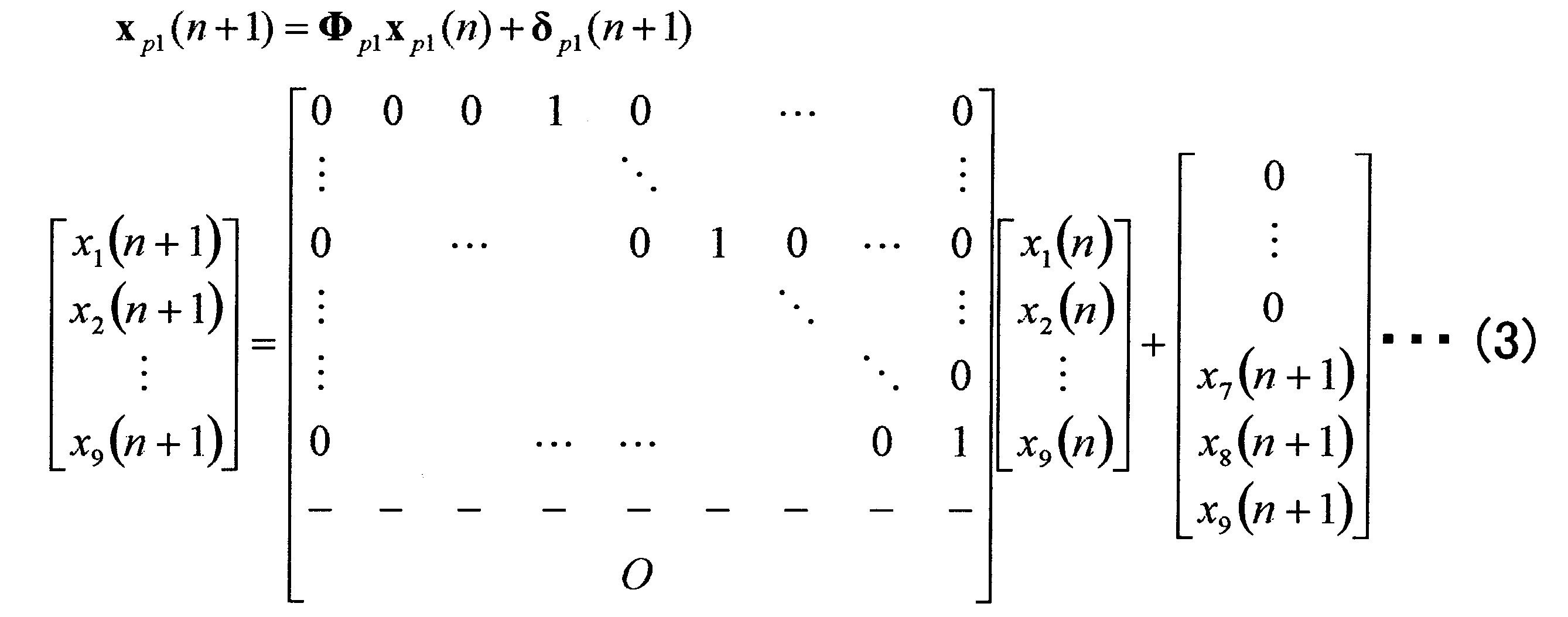
図6は、式(3)で表される状態方程式の構成を説明するための図である。
式(3)で表される状態方程式の特徴は、状態遷移行列Φp1の一部の要素を「1」に設定し、残りの要素をすべて「0」に設定した点、および、駆動源ベクトルδp1(n)の一部の要素を有色信号である状態量xi(n)(i=7,8,9)で表した点にある。これは、図6に示すように、現在の時刻n+1における処理対象ブロックと過去の時刻nにおける処理対象ブロックとが重なる部分において、現在の状態量(原画像の画素情報)x1(n+1)、x2(n+1)、x3(n+1)、x4(n+1)、x5(n+1)、x6(n+1)と過去の状態量(原画像の画素情報)x4(n)、x5(n)、x6(n)、x7(n)、x8(n)、x9(n)とを対応させるためである。この結果、xp1(n)とxp1(n+1)の関係を表す状態方程式は、クリアな画像からなるxp1(n)と、0と1からなるΦp1と、有色信号であるクリアな画像からなる駆動源ベクトルδp1(n)とから構成されるため、所望の状態量(原画像の画素情報)、つまり、クリアな画像情報(原画像情報)のみで構成されることになる。
図7は、発明手法の観測方程式の定式化の具体例を説明するための図であり、特に、図7Aは、状態空間モデルの観測過程を示す図、図7Bは、観測方程式の具体例を示す図である。
図5および図6の例に対応して、式(2)における観測方程式は、図7Bにも示す次の式(4)で定義される。ここで、観測ベクトルyp1(n)は、劣化画像情報を含む観測量として3×3の処理対象ブロックに含まれる9個の画素情報y1(n)、y2(n)、y3(n)、y4(n)、y5(n)、y6(n)、y7(n)、y8(n)、y9(n)を要素とする9×1次のベクトルである。また、観測遷移行列Mp1は、式(4)で定義された9×9次の行列であって、画像の劣化モデルにおけるぼけの点拡がり関数(PSF)に対応している。観測遷移行列Mp1を構成する各要素hr,s(r,sはhの座標であり、r,s=-1,0,1)は、既知であって、予めデータ化して適切に設定されている。また、観測雑音ベクトルεp1(n)は、3×3の処理対象ブロックに含まれる9個の画素に対応する観測雑音ε1(n)、ε2(n)、ε3(n)、ε4(n)、ε5(n)、ε6(n)、ε7(n)、ε8(n)、ε9(n)を要素とする9×1次のベクトルである。
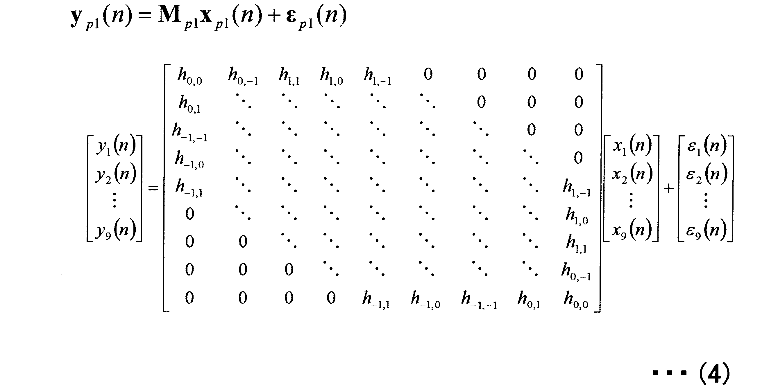
図8は、従来の一般的な観測方程式の構成(一般例)を説明するための図であり、図9は、式(4)で表される観測方程式の構成を説明するための図である。特に、図8Aは、従来一般的な観測方程式の定義を示す図、図8Bは、観測量に影響する状態量の範囲を視覚的に示す図である。また、図9Aは、発明手法の観測方程式の定義を示す図、図9Bは、観測量に影響する状態量の範囲を視覚的に示す図である。なお、図8および図9の説明においては、便宜上、観測雑音ベクトルεp1(n)は省略する。
画像においてぼけに基づく劣化とは、上記のように、ある画素がその周囲の画素の影響を受けて劣化することである。そこで、従来は、一般的に、図8Aに示すように観測方程式を定義していた。この場合、ぼけは、周囲のすべての画素の影響を受けることに起因して生じる。すなわち、処理対象ブロックの中の各画素は、処理対象ブロックの中のすべての画素の影響を受けることになる。言い換えれば、各観測量yi(i=1,2,…,9)は、すべての状態量xi(i=1,2,…,9)の影響を受けて成り立つ。これを視覚的に示すと、例えば、図8Bに示すようになる。すなわち、図8Bに示すように、例えば、観測量がy1の場合もy2の場合も、3×3(=9)個のすべての状態量x1~x9の影響を受けることになる。
これに対し、式(4)で表される観測方程式の特徴は、観測遷移行列Mp1の一部の要素を、3×3(=9)個の係数hr,s(r,s=-1,0,1)を用いて規則的に設定し、残りの要素をすべて「0」に設定した点にある。例えば、図9Aは、観測方程式を展開して得られる一部の式(y1(n)、y2(n)に関する式)を示している。観測遷移行列Mp1に対する係数hr,sの割り当て方法は、次の通りである。すなわち、9個の係数hr,s(r,s=-1,0,1)を図10に示すようにマトリックス状に配列し(以下「係数マトリックス」という)、係数マトリックスの中央(つまり、係数h0,0)の位置を観測量yi(i=1,2,…,9)の注目画素iの位置に合わせたときの、その係数マトリックスに従って、観測遷移行列Mp1の一部の要素に係数hr,s(r,s=-1,0,1)を割り当てる。これを視覚的に示すと、例えば、図9Bに示すようになる。すなわち、図9Bに示すように、例えば、観測量がy1の場合は、3×3(=9)個の状態量x1~x9のうち、5個のx1~x5の影響を受け、観測量がy2の場合は、6個のx1~x6の影響を受けることになる。
図11は、図9Aに示す観測遷移行列Mp1に基づく、各観測量yiに影響する状態量xiの範囲を、割り当てられた係数hr,s(r,s=-1,0,1)と共に示す図である。なお、ここでは、説明の便宜上、図11A~図11Iの各図において、左側の処理対象ブロックには、注目する観測量yiのみを示し、右側の処理対象ブロックには、影響を与える各状態量xiの場所に、この状態量xiに乗算されるhr,sのみを示している。
式(4)で表される観測方程式では、観測量y1は、図11Aに示すように、5個の状態量x1~x5の影響を受け、観測量y2は、図11Bに示すように、6個の状態量x1~x6の影響を受け、観測量y3は、図11Cに示すように、7個の状態量x1~x7の影響を受ける。また、観測量y4は、図11Dに示すように、8個の状態量x1~x8の影響を受け、観測量y5は、図11Eに示すように、9個すべての状態量x1~x9の影響を受け、観測量y6は、図11Fに示すように、8個の状態量x2~x9の影響を受ける。また、観測量y7は、図11Gに示すように、7個の状態量x3~x9の影響を受け、観測量y8は、図11Hに示すように、6個の状態量x4~x9の影響を受け、観測量y9は、図11Iに示すように、5個の状態量x5~x9の影響を受ける。
図12は、発明手法のアルゴリズムの一例を示す図である。なお、このアルゴリズムは、画像の種類を問わず、静止画像のみならず動画像にも適用可能である。
発明手法1のアルゴリズムは、図12に示すように、初期設定(Initialization)の過程と反復(Iteration)の過程とに大別され、反復過程は、新しい状態空間モデル(状態方程式と観測方程式)を基に構成されている。反復過程では、1~6の手順を逐次繰り返す。
図13は、図12のアルゴリズムを実行する処理手順を示すフローチャートである。
まず、初期設定部162で、初期設定を行う(S1000)。具体的には、初期設定部162において、状態ベクトル、つまり、状態量である所望信号(原画像信号)ベクトルの最適推定値(以下「所望信号の最適推定値ベクトル」という)の初期値xp1(0|0)、所望信号ベクトルの推定誤差(以下「所望信号の推定誤差ベクトル」という)の相関行列の初期値Pp1(0|0)、駆動源ベクトルの共分散の値Rδp1(n)[i,j]、および、観測雑音ベクトルの共分散の値Rεp1(n)[i,j]を、次の式(5)に示すようにそれぞれ設定する。また、図12では図示しないが、状態遷移行列Φp1および観測遷移行列Mp1を、式(3)および式(4)に示すようにそれぞれ設定する。なお、ここでは、時刻nのカウンタの初期値を「0」に設定している。また、ベクトルと行列の要素を示す場合、ベクトルa(n)のi番目の要素をa(n)[i]と表記し、行列A(n)のi行j列の要素をA(n)[i,j]と表記することとする。また、図12において、所望信号の最適推定値ベクトルxp1は、ハットxp1と表記する。
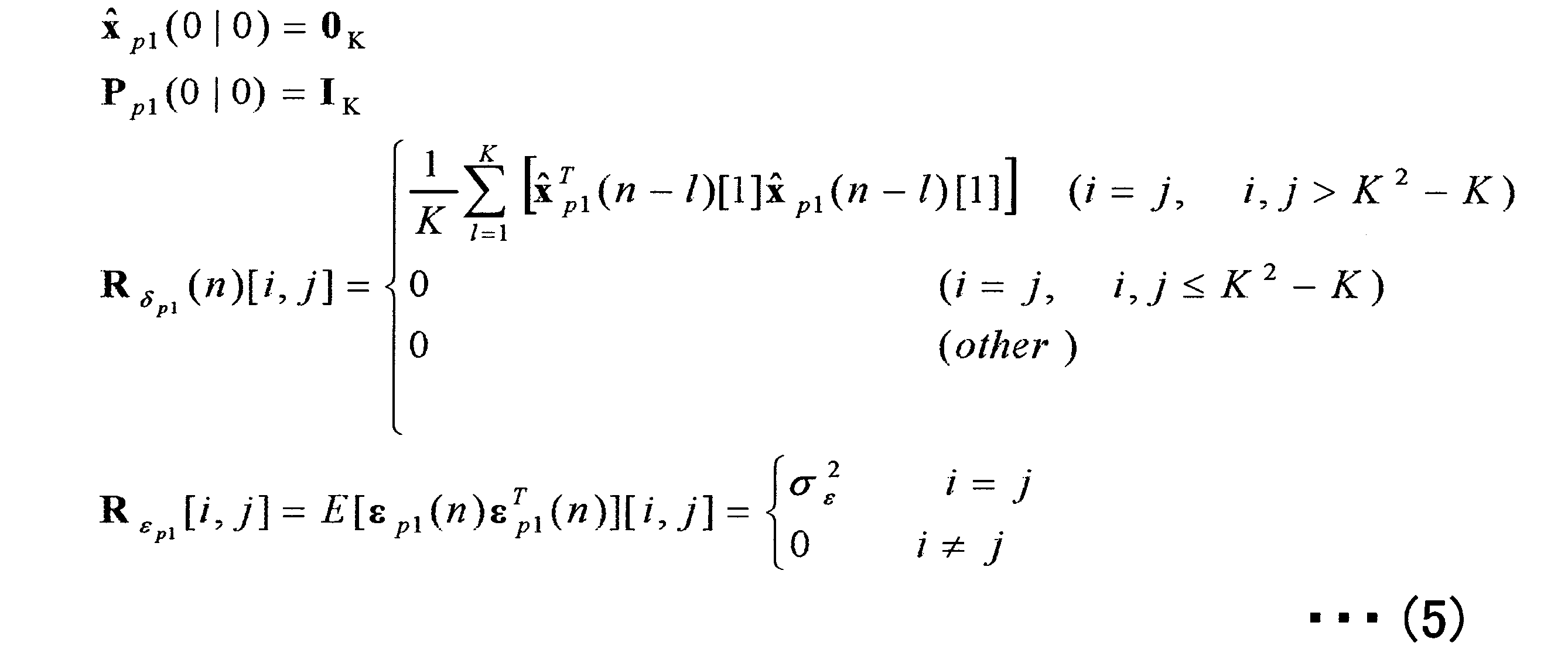
ただし、ベクトル0Kは、K次元の零ベクトルであり、行列IKは、K次の単位行列である。また、Kは、K×Kの大きさの注目領域のその次元である。K=3の場合、K2-K=6となり、「i,j>K2-K」は、「i,j=7,8,9」に対応している。また、E[δp1(n),δp1
T(n)]は、駆動源ベクトルδp1(n)の自己相関行列である。E[εp1(n)εp1
T(n)][i,j]は、観測雑音ベクトルεp1の自己相関行列であり、ここではσ2
ε[i,j]と等しく、既知と仮定している。ここでいう「既知」とは、別の任意の方法(アルゴリズム)で求められて与えられることを意味する。もし観測雑音ベクトルεp1(n)が白色雑音であり零平均であれば、σ2
εは所定のサンプル数の分散で与えられる。
次に、相関演算部164で、n→(n+1)の誤差共分散行列、つまり、n→(n+1)の推定誤差の相関値(行列)(以下「相関行列」ともいう)を計算する(S1100)。具体的には、相関演算部164において、時刻nまでの情報により時刻n+1での所望信号ベクトルを推定した場合の誤差(所望信号の推定誤差ベクトル)の相関行列Pp1(n+1|n)を計算する。この計算は、ステップS1000でそれぞれ設定した状態遷移行列Φp1および駆動源ベクトルの共分散Rδp1(n+1)[i,j]の値、ならびに、ステップS1000で設定した(n=0の場合)または前回のステップS1600で計算した(n≧1の場合)所望信号の推定誤差ベクトルの相関行列Pp1(n|n)を用いて、次の式(6)により行う。なお、このステップS1100は、図12の反復過程の手順1に相当する。

次に、重み係数算出部166で、重み係数(行列)の計算を行う(S1200)。具体的には、重み係数算出部166において、観測量である観測信号ベクトルの推定誤差(以下「観測信号の推定誤差ベクトル」という)に重み係数(行列)をかけて、時刻nまでの情報による時刻n+1での所望信号の最適推定値ベクトルxp1(n+1|n)を加えたものが、時刻n+1までの情報による時刻n+1での所望信号の最適推定値ベクトルxp1(n+1|n+1)になるような、その重み係数行列Kp1(n+1)を計算する。この計算は、ステップS1100で計算した所望信号の推定誤差ベクトルの相関行列Pp1(n+1|n)、ならびに、ステップS1000でそれぞれ設定した観測遷移行列Mp1および観測雑音ベクトルの共分散Rεp1(n+1)[i,j]の値を用いて、次の式(7)により行う。なお、このステップS1200は、図12の反復過程の手順2に相当する。

次に、最適推定値算出部168で、n→(n+1)の状態量(所望信号)の最適推定値(ベクトル)を計算する(S1300)。具体的には、最適推定値算出部168において、時刻nまでの情報による時刻n+1での所望信号の最適推定値ベクトルxp1(n+1|n)を計算する。この計算は、ステップS1000で設定した状態遷移行列Φp1、および、前回のステップS1400で計算した所望信号の最適推定値ベクトルxp1(n|n)を用いて、次の式(8)により行う。なお、このステップS1300は、図12の反復過程の手順3に相当する。

次に、同じく最適推定値算出部168で、(n+1)→(n+1)の状態量(所望信号)の最適推定値(ベクトル)を計算する(S1400)。具体的には、最適推定値算出部168において、時刻n+1までの情報による時刻n+1での所望信号の最適推定値ベクトルxp1(n+1|n+1)を計算する。この計算は、ステップS1300で計算した所望信号の最適推定値ベクトルxp1(n+1|n)、ステップS1200で計算した重み係数行列Kp1(n+1)、ステップS1000で設定した観測遷移行列Mp1、および時刻n+1における観測信号ベクトルyp1(n+1)を用いて、次の式(9)により行う。なお、このステップS1400は、図12の反復過程の手順4に相当する。

次に、処理を終了するか否かを判断する(S1500)。この判断は、例えば、時刻nが所定のサンプル数Nに達したか否かを判定することによって行う。この判断の結果として、時刻nが所定のサンプル数Nに達していない場合は(S1500:NO)、ステップS1600に進み、時刻nが所定のサンプル数Nに達した場合は(S1500:YES)、ステップS1800に進む。なお、判断の基準は、上記の例に限定されない。例えば、リアルタイムで処理を行う場合は、時刻nが所定のサンプル数Nに達していなくても、サンプルがなくなった時点で処理を終了するようにしてもよい。
ステップS1600では、相関演算部164で、(n+1)→(n+1)の誤差共分散行列、つまり、(n+1)→(n+1)の推定誤差の相関値(行列)を計算する。具体的には、相関演算部164において、時刻n+1までの情報により時刻n+1での所望信号ベクトルを推定した場合の誤差(所望信号の推定誤差ベクトル)の相関行列Pp1(n+1|n+1)を計算する。この計算は、ステップS1200で計算した重み係数行列Kp1(n+1)、ステップS1000で設定した観測遷移行列Mp1、およびステップS1100で計算した所望信号の推定誤差ベクトルの相関行列Pp1(n+1|n)を用いて、次の式(10)により行う。なお、このステップS1600は、図12の反復過程の手順5に相当する。

次に、ステップS1700では、時刻nのカウンタを1だけインクリメントして(n=n+1)、ステップS1100に戻る。
一方、ステップS1800では、本アルゴリズムの計算結果を出力値として一時保存する。具体的には、ステップS1400で計算した所望信号の最適推定値ベクトルxp1(n+1|n+1)を、本アルゴリズムの出力値として画像復元処理部160内または記憶部150内に一時保存する。
図14は、発明手法を視覚的にまとめた説明図である。このように、発明手法では、新しい状態空間モデル(状態方程式と観測方程式)を構成しているため、1段階処理で画像の復元処理が可能となる。このことは、本発明の大きな特徴の1つである。
ここで、カルマンフィルタを用いた従来の画像復元手法との対比において、発明手法の特徴と効果をまとめて説明しておく。
カルマンフィルタを用いた従来の画像復元手法では、上記のように、2段階処理(ステップ1で、AR次数を決定し、AR係数を推定した後、ステップ2で、この推定したAR係数を用いて状態空間モデル(状態方程式と観測方程式)を構成してカルマンフィルタを実行する)によって、画像の復元を実現している。したがって、ステップ1でのAR次数の決定およびAR係数の推定の精度によってステップ2でのカルマンフィルタによる画像復元能力が大きく左右されることが、容易に予想される。これに対して、発明手法では、ARシステムのコンセプトを必要としない新しい状態空間モデル(状態方程式と観測方程式)を構成し、これを用いた1段階処理の新しい予測法によって、高性能な画像復元を実現している。また、発明手法では、処理ステップを1段階減らすことができるため、演算量を削減することができ、ひいては、回路規模の縮小やメモリ容量の削減などを図ることができる。
また、カルマンフィルタを用いた従来の画像復元手法では、ステップ1でAR係数の推定を行う際に必要となるAR係数の次数の決定が大きな問題点となる。一般にAR係数の次数は状態量に依存しているため、状態量が既知でなければ、理論的にAR係数の次数を正確に決定することは困難である。このことは、状態量が既知でなければならないことを意味しているため、リアルタイム処理は困難となる。また、それにより、正確でないAR係数の次数を用いることになるため、正確なAR係数の推定は困難である。したがって、このことは、カルマンフィルタを用いた従来の画像復元手法の画像復元能力を低下させる大きな要因となっている。また、何らかの技術でAR次数とAR係数をリアルタイムに推定できるようになったとしても、処理ステップが1段階増えることより演算量の増加は避けられない。これに対して、発明手法では、ARシステムのコンセプトを必要としないため、このような問題は生じない。
また、カルマンフィルタを用いた従来の画像復元手法では、状態量をARシステムを用いて表現することによってモデル化している。このことは、カルマンフィルタを用いた従来の画像復元手法はARシステムでモデル化可能な状態量にしか適用できないことを意味している。すなわち、カルマンフィルタを用いた従来の画像復元手法は、ARシステムでモデル化が困難な状態量には適用することができない。これに対して、発明手法は、ARシステムのコンセプトを必要としないため、適用対象に関するこのような制約は存在しない。
また、カルマンフィルタを用いた従来の画像復元手法では、状態方程式の駆動源が白色信号で、かつ、状態量と観測雑音が無相関であることを仮定した上で、カルマンフィルタ理論を適用している。これに対して、発明手法では、駆動源が有色信号(クリアな画像)となるものの、状態方程式と観測方程式の特殊な構成によって発明手法のアルゴリズムを実行することができる。このことは、発明手法は、カルマンフィルタ理論の一般的な適用条件を考慮しなくても実行可能であることを意味している。すなわち、発明手法は、カルマンフィルタ理論よりも適用範囲が広いといえる。
したがって、ARシステムのコンセプトを必要としない発明手法は、画像の撮り直しが許されない場面、例えば、医療分野における瞬間的な心臓や肺などの画像復元、汚れなどで劣化した古文書などの復元、および文字・物体認識においても貢献可能な技術である。
また、本発明者は、本発明の効果(発明手法の有効性)を実証するためにシミュレーションを行った。具体的には、発明手法1の画像復元能力を評価するために、(1)視覚評価、(2)客観評価、および(3)主観評価を行った。視覚評価は、原画像と復元画像とを視覚により比較した評価である。客観評価は、数値による評価である。主観評価は、聞き取り調査である。以下、これらを順に説明する。
まず、シミュレーション条件について説明しておく。
図15は、シミュレーション条件を説明するための図である。
本シミュレーションでは、原画像として、図15に示す2つの画像、つまり、(a)「カメラマン(Cameraman)」と(b)「レナ(Lenna)」を用いた。また、原画像に加えるぼけに対応する点拡がり関数(PSF)のモデルとして、図15に示す2次元ガウス関数を用い、雑音として、加法性白色ガウス雑音を用いた。また、信号対雑音比SNRを30dBとした。また、比較のため、シミュレーションは、同一の上記シミュレーション条件の下で、従来手法1(ウィナーフィルタを用いた画像復元手法)と、従来手法2(射影フィルタを用いた画像復元手法)と、従来手法3(カルマンフィルタを用いた画像復元手法)と、発明手法(発明手法1)に対して行った。例えば、画像「カメラマン」は、図16に示すように、空の部分は画像の分散が変化していないため定常性が強く、人物の頭の部分は画像の分散が変化しているため非定常性が強いといえる。
(1)視覚評価
図17は、原画像「カメラマン」に対するシミュレーション結果(視覚評価)を示す図であり、図18は、図17中の破線の円の周辺領域を拡大した図である。
図17は、原画像「カメラマン」に対するシミュレーション結果(視覚評価)を示す図であり、図18は、図17中の破線の円の周辺領域を拡大した図である。
図18によく示すように、従来手法1は、ぼけがほとんど取り除かれていない。また、従来手法2は、従来手法1よりもぼけが取り除かれているが、原画像と比べるとまだぼけが残っている。一方、従来手法3は、従来手法1、2に比べて、ぼけは取り除かれてくっきりしているように見えるが、原画像とは異なった復元画像となっている。特に、従来手法3は、原画像と比べて全体的に暗くなっており、空の部分においては、劣化画像よりも劣化してしまっている。
これに対して、発明手法は、図18によく示すように、従来手法1、2、3に比べて原画像を忠実に復元していることが確認できる。すなわち、図18の拡大画像においても、発明手法の有効性を確認することができる。
図19は、原画像「カメラマン」に対するシミュレーション結果(視覚評価)を示す図であり、図20は、図19中の破線の円の周辺領域を拡大した図である。
図20によく示すように、カメラの三脚部分に注目すると、従来手法1は、全くぼけが取り除かれていない。また、従来手法2は、従来手法1よりはぼけが取り除かれているが、原画像までは復元されていない。一方、従来手法3は、従来手法1、2に比べるとぼけは取り除かれているように見えるが、画像全体が荒れてしまっており、原画像とかけ離れた復元画像となっていることが確認できる。
これに対して、発明手法は、図20によく示すように、従来手法1、2、3に比べて原画像をより忠実に復元していることが確認できる。すなわち、図20の拡大画像においても、発明手法の有効性を確認することができる。
図21は、原画像「レナ」に対するシミュレーション結果(視覚評価)を示す図であり、図22は、図21中の破線の円の周辺領域を拡大した図である。
図22によく示すように、従来手法1は、ほとんどぼけが取り除かれておらず、復元画像が原画像と比べて全体的に白くなっている(輝度が高くなっている)。また、従来手法2は、従来手法1に比べるとぼけは取り除かれているが、原画像まではぼけが取り除かれていない。一方、従来手法3は、従来手法1、2に比べるとぼけが取り除かれておりはっきりとしているように見えるが、劣化画像よりも劣化してしまっており、原画像とはかけ離れた画像になっている。特に肌の部分に注目すると、この点が顕著に表れている。
これに対して、発明手法は、図22によく示すように、従来手法1、2、3に比べて原画像を忠実に復元していることが確認できる。すなわち、図22の拡大画像においても、発明手法の有効性を確認することができる。
(2)客観評価(数値による評価)
図23は、原画像に対するシミュレーション結果(客観評価)を示す図である。
図23は、原画像に対するシミュレーション結果(客観評価)を示す図である。
ここでは、従来手法と発明手法の画像復元能力を数値により評価するため、図23にも示す次の式(11)で表されるSNRout[dB]を用いて画像復元能力を評価した。なお、SNRは、信号に対する雑音の比であり、数値が大きいほど劣化(ぼけや雑音など)が少なく画像として良好であるといえる。

この場合、図23に示すように、「カメラマン」、「レナ」どちらの画像についても、発明手法は、従来手法1、2、3よりもSNRoutの数値が大きいことが確認できる。これにより、発明手法は、客観評価の点でも、従来手法1、2、3に比べて画像復元能力が高いことがわかる。
(3)主観評価(聞き取り調査)
図24は、原画像に対するシミュレーション結果(主観評価)を示す図である。
図24は、原画像に対するシミュレーション結果(主観評価)を示す図である。
ここでは、従来手法と発明手法の画像復元能力を評価するために、聞き取り調査による主観評価を行った。画像復元の性能評価は、ACR(絶対範疇評価)に基づく5段階MOS(平均オピニオン値)を用いた聞き取り調査により行った。MOS評価基準は、図24に示す通りである。50人の聴取者が画像復元により得られた画像(図17~図22参照)を評価した。各々の聴取者は、評価値「1」から「5」を決定する。評価値「5」が最良である。
図24に示すように、MOS評価は、「カメラマン」、「レナ」どちらの画像についても、発明手法は、従来手法1、2、3よりも高い評価を得ていることが確認できる。これにより、発明手法は、主観評価の点でも、従来手法1、2、3に比べて画像復元能力が高いことがわかる。
以上のシミュレーション結果により、本発明の画像復元方法(発明手法1)は、従来手法に比べて高い画像復元能力を発揮していることがわかる。特に、図17~図22の視覚評価から明らかなように、本発明の画像復元方法は、非定常性が強いエッジ部分などにおいて、従来手法に比べて著しく復元精度が高いことがわかる。
次いで、上記構成を有する画像復元装置100の動作について、図25に示すフローチャートを用いて説明する。なお、図25に示すフローチャートは、記憶部150(主記憶装置152または補助記憶装置154)に制御プログラムとして格納されており、図示しないCPUによって実行される。
まず、ステップS2000では、画像入力装置110から復元処理対象の画像データ(劣化画像)を取り込み、記憶部150(主記憶装置152または補助記憶装置154)の所定の記憶領域に格納する。
そして、ステップS2050では、ステップS2000で取り込んだ画像データを表示メモリ156に書き込んで、ディスプレイ182に表示する。
そして、ステップS2100では、操作部130の領域指定部134で、領域指定処理を行う。具体的には、使用者の入力操作により、ステップS2050でディスプレイ182に表示した画像のうち画像復元処理の対象となる領域(画像の特定の範囲)が指定されると、その指定された領域のデータを生成する。領域の指定は、例えば、画面上、ポインタなどで行われる。なお、使用者により領域の指定が行われなかった場合は、表示された画像全体を指定したものとして取り扱われる。
そして、ステップS2150では、拡大処理を行うか否かを判断する。この判断は、例えば、ステップS2100で生成した指定領域データに基づいて行われる。具体的には、指定された領域が表示された画像全体よりも小さい場合には、拡大処理を行うと判断する。この判断の結果として、拡大処理を行う場合は(S2150:YES)、ステップS2200に進み、拡大処理を行わない場合は(S2150:NO)、直ちにステップS2250に進む。
ステップS2200では、ステップS2100で指定した領域の拡大処理を行う。具体的には、例えば、指定された領域が表示された画像全体に対応する大きさとなるように拡大処理を行う。拡大処理の結果は、記憶部150(主記憶装置152または補助記憶装置154)の作業用メモリに書き込まれる。なお、拡大処理が行われなかった場合も、その画像データは作業用メモリに書き込まれる。
そして、ステップS2250では、時刻nの処理対象ブロック(例えば、3×3の大きさ)を選択する。
そして、ステップS2300では、ステップS2250で選択した処理対象ブロックに対して、画像の急激な変化領域が検出されたか否かを判断する。画像の急激な変化領域は、例えば、画像のエッジ部分などに相当する。具体的には、例えば、作業用メモリに書き込まれた画像データ(拡大処理の有無を問わず)に対して、ステップS2250で選択した処理対象ブロック(3×3の大きさ)上で画素データを順次スキャンすることにより、急激な画素データの変化点があるか否かを検出する。この判断の結果として、画像の急激な変化領域が検出された場合は(S2300:YES)、ステップS2350に進み、画像の急激な変化領域が検出されなかった場合は(S2300:NO)、ステップS2400に進む。
具体的な検出方法の一例は、次の通りである。ある一定量の過去の観測量の平均値y’(n-1)と現在の観測量y(n)との差の絶対値、つまり、|y’(n-1)-y(n)|の値をしきい値αと比較する。そして、その値がしきい値α以上の場合、つまり、|y’(n-1)-y(n)|≧αの場合は、急激な画素データの変化点があると判断し、その値がしきい値α未満の場合、つまり、|y’(n-1)-y(n)|<αの場合は、急激な画素データの変化点はないと判断する。例えば、図26において、時刻n-1の処理対象ブロック301における所定部分302の観測量の平均値y’(n-1)と、時刻nの処理対象ブロック303における注目画素の部分304の観測量y(n)とを比較する。
ステップS2350では、ステップS2250で選択した処理対象ブロックに対して、発明手法による画像復元処理を行う。発明手法による画像復元処理は、上記のように、急激な画素データの変化点がある場合、つまり、エッジ部分などを含む場合であっても、高精度な復元処理が可能である。なお、発明手法による画像復元処理の詳細な手順の一例については、図13のフローチャートを用いて説明した通りである。
一方、ステップS2400では、ステップS2250で選択した処理対象ブロックに対して、発明手法以外の他の画像復元手法による画像復元処理を行う。他の画像復元手法としては、ウィナーフィルタを用いた画像復元手法や射影フィルタを用いた画像復元手法、カルマンフィルタを用いた画像復元手法などを含む任意の画像復元手法を用いることができる。急激な画素データの変化点がない場合、つまり、エッジ部分などを含まない場合には、他の画像復元手法でも精度良く復元処理を行うことができるからである。
そして、ステップS2450では、ステップS2350での復元処理結果またはステップS2400での復元処理結果を、順次、記憶部150(主記憶装置152または補助記憶装置154)の作業用メモリに保存する。
そして、ステップS2500では、時刻nのカウンタの値を1だけインクリメントする。
そして、ステップS2550では、1頁分の画像復元処理が終了したか否かを判断する。この判断は、時刻nのカウンタの値に基づいて行われる。この判断の結果として、1頁分の画像復元処理が終了した場合は(S2550:YES)、ステップS2600に進み、1頁分の画像復元処理が終了していない場合は(S2550:NO)、ステップS2250に戻る。
ステップS2600では、1頁分の画像復元処理が終了したため、表示メモリ156の更新処理を行う。すなわち、ここでは、1頁分の画像復元処理が終了した時点で表示メモリ156を更新するように構成されている。
そして、ステップS2650では、ステップS2000で取り込んだ画像データの全頁分に対して画像復元処理が終了したか否かを判断する。この判断の結果として、全頁分の画像復元処理が終了していない場合は(S2650:NO)、ステップS2250に戻り、全頁分の画像復元処理が終了した場合は(S2650:YES)、上記一連の処理を終了する。
次に、ぼけ情報である点拡がり関数(PSF)に対応する観測遷移行列Mp1の設定と実装の具体例について、図27および図28を用いて説明する。
図27は、復元モードの実装の一例を説明するための図である。
上記のように、観測遷移行列Mp1は、式(4)で定義された9×9次の行列であって、画像の劣化モデルにおけるぼけの点拡がり関数(PSF)に対応しており、観測遷移行列Mp1を構成する各要素hr,s(r,s=-1,0,1)は、既知であって、予めデータ化して適切に設定されている。すなわち、本実施の形態では、画像によってぼけ具合が変わるため、いわばぼけ情報である観測遷移行列Mp1の各要素hr,sの値の組を復元モードとしていくつか予め設定しておき、使用者は、操作部130の復元モード指定部136を介して、その復元モードを任意に指定できるように構成されている。例えば、図27の例では、デジタルカメラなどによく設定されている夜景モードやスポーツモードなどの撮影モード毎に、予め、その撮影モードに合った適切な観測遷移行列Mp1がそれぞれ設定されている。したがって、使用者は、撮影モードを切り替えることによって、最適な復元モードを使用することができる。なお、復元モード(観測遷移行列Mp1の各要素hr,sの値)自体を自動または手動で再調整することも可能である。
図28は、復元モードの実装の他の例を説明するための図である。
図28の例では、画像によってぼけ具合が変わるため、まず、図28(A)に示すように、ディスプレイ182上で、処理対象の劣化画像を選択した後、図28(B)に示すように、観測遷移行列Mp1(各要素hr,sの値)を変えた復元画像をいくつかディスプレイ182に表示する。このとき、使用者が、例えば、操作部130(タッチパネルなど)を介して、ディスプレイ182に表示された複数の復元画像の中から、最適な復元画像を選択すると、復元画像が決定される。なお、使用者の選択の履歴をデータとして蓄積することによって、使用者の好みに合った復元モード(観測遷移行列Mp1の各要素hr,sの値)を自動で選択することも可能となる。
このように、本実施の形態によれば、ARシステムのコンセプトを必要としない新しい状態空間モデル(状態方程式と観測方程式)を構成して1段階処理の新しい予測法によって画像復元を行うため、シンプルで実用的かつ高性能な画像復元を実現することができる。すなわち、AR次数の決定およびAR係数を推定するステップを必要としないシンプルな構成で、かつ、非定常性が強い自然画像に対しても有効に復元処理を行うことができる実用性を有し、しかも、従来手法に比べて画像復元能力を向上することができる。
また、本実施の形態では、上記のように、ARシステムのコンセプトを必要としないため、画像の撮り直しが許されない場面にも広く適用可能である。なお、もちろん、ここでも、上記のように、画像の種類は限定されず、静止画像でも動画像でもよい。
例えば、古文書の傷や汚れなどをぼけや雑音とみなし、発明手法を用いてこれらを取り除き、文字・物体認識技術を用いることによって、古文書の解読、復元、およびデジタルデータベース化に効果を発揮することが期待される。
また、防犯分野においても、近年、防犯カメラ(監視カメラ)などの設置が普及しつつあり、犯罪者の多くは防犯カメラなどに撮影されていることが多いため、この画像が犯罪者の発見の手がかりとなることがある。しかし、これらの画像は一般に画質が荒く、動いている対象物の画像はぼけが生じていることが一般的である。また、これらの画像を拡大した場合には、通常、画像はより一層劣化する。そこで、拡大画像を含めてこれらの劣化画像に発明手法を適用することによって、劣化画像のぼけと雑音を取り除き、クリアな画像を提供することで、犯罪者の早期発見につながることが期待される。なお、このように、拡大画像を含めて劣化画像に発明手法を適用することによって、劣化画像のぼけと雑音を取り除き、クリアな画像を提供することは、防犯分野に限らず、監視カメラなどで撮影された画像に基づいて、事故の判定や器具の故障診断などを行う場合にも適用可能である。
また、近年、カメラ機能付き携帯電話やデジタルカメラなどが急速な勢いで普及し、1人1台の時代となっている。しかし、これらの製品に搭載されている画像復元技術は、顔認識やフィルタなどのぼけや雑音を予防する技術であり、撮り直しが許されない場面を想定していない。したがって、これらの製品に発明手法を適用することによって、撮り直しが許されない瞬間的な画像復元が可能になる。
また、医療の分野において、健康を調査する最も効果的な手段の1つとして、内視鏡やレントゲン、エコー、CT、MRIなどの画像診断がある。例えば、肺や心臓などの画像診断では、肺や心臓などの動作によってぼけと雑音を含んだ情報から健康診断を行っている。これらの画像診断に発明手法を適用してぼけと雑音を取り除くことによって、専門医にクリアな画像を迅速に提供することが可能となり、病気の早期発見の一助になることが期待される。
また、近年カーナビゲーションシステムが普及していることから、フロント・リアカメラを搭載した自動車も増えている。このようなリアルタイムで画像復元処理が必要な自動車のフロント・リアカメラなどの場合においても発明手法は有効である。
2008年8月8日出願の特願2008-206316の日本出願に含まれる明細書、図面および要約書の開示内容は、すべて本願に援用される。
本発明に係る画像復元装置および画像復元方法は、画像復元能力を向上することができるシンプルで実用的な画像復元装置および画像復元方法として有用である。
100 画像復元装置
110 画像入力装置
112 カメラ
114 スキャナ
116、186 記録メディア
118、188 モデム
120 入力インタフェース部
130 操作部
132 パラメータ設定部
134 領域指定部
136 復元モード指定部
140 内部インタフェース部
150 記憶部
152 主記憶装置
154 補助記憶装置
156 表示メモリ
160 画像復元処理部
160a 第1復元処理部
160b 第2復元処理部
162 初期設定部
164 相関演算部
166 重み係数算出部
168 最適推定値算出部
170 出力インタフェース部
180 画像出力装置
182 ディスプレイ
184 プリンタ
110 画像入力装置
112 カメラ
114 スキャナ
116、186 記録メディア
118、188 モデム
120 入力インタフェース部
130 操作部
132 パラメータ設定部
134 領域指定部
136 復元モード指定部
140 内部インタフェース部
150 記憶部
152 主記憶装置
154 補助記憶装置
156 表示メモリ
160 画像復元処理部
160a 第1復元処理部
160b 第2復元処理部
162 初期設定部
164 相関演算部
166 重み係数算出部
168 最適推定値算出部
170 出力インタフェース部
180 画像出力装置
182 ディスプレイ
184 プリンタ
Claims (16)
- 原画像情報に不必要な情報が混在した劣化画像情報のみから前記原画像情報を推定する画像復元装置であって、
時刻nのみの劣化画像情報に対して、時刻nまたは時刻n+1までの情報により前記原画像情報を含む時刻n+1でのシステムの状態量を推定した場合の推定誤差の相関値を算出する相関演算部と、
時刻nのみの劣化画像情報に対して、前記相関演算部によって算出された相関値を用いて、時刻n+1までの情報による時刻n+1での前記状態量の最適推定値と、時刻nまでの情報による時刻n+1での前記状態量の最適推定値と、前記劣化画像情報を含む観測量の推定誤差と、の関係を規定するための重み係数を算出する重み係数算出部と、
時刻nのみの劣化画像情報に対して、前記重み係数算出部によって算出された重み係数を用いて、時刻nまたは時刻n+1までの情報による時刻n+1での前記状態量の最適推定値を算出する最適推定値算出部と、
を有する画像復元装置。 - 前記相関演算部は、第1の相関演算部および第2の相関演算部を有し、
前記最適推定値算出部は、第1の最適推定値算出部および第2の最適推定値算出部を有し、
前記第1の相関演算部は、
時刻nのみの劣化画像情報に対して、時刻nまでの情報により前記原画像情報を含む時刻n+1でのシステムの状態量を推定した場合の推定誤差の相関値行列を算出し、
前記重み係数算出部は、
時刻nのみの劣化画像情報に対して、前記第1の相関演算部によって算出された推定誤差の相関値行列を用いて、時刻n+1までの情報による時刻n+1での前記状態量の最適推定値と、時刻nまでの情報による時刻n+1での前記状態量の最適推定値と、前記劣化画像情報を含む観測量の推定誤差と、の関係を規定するための重み係数行列を算出し、
前記第1の最適推定値算出部は、
時刻nのみの劣化画像情報に対して、時刻nまでの情報による時刻n+1での前記状態量の最適推定値ベクトルを算出し、
前記第2の最適推定値算出部は、
時刻nのみの劣化画像情報に対して、前記重み係数算出部によって算出された重み係数行列を用いて、時刻n+1までの情報による時刻n+1での前記状態量の最適推定値ベクトルを算出し、
前記第2の相関演算部は、
時刻nのみの劣化画像情報に対して、時刻n+1までの情報により時刻n+1の前記状態量を推定した場合の推定誤差の相関値行列を算出する、
請求項1記載の画像復元装置。 - 前記第1の相関演算部は、
所定の状態行列、与えられた駆動源ベクトルの共分散の要素値、および与えられたまたは前回前記第2の相関演算部によって算出された推定誤差の相関値行列を用いて、前記推定誤差の相関値行列の算出を行い、
前記重み係数算出部は、
前記第1の相関演算部によって算出された推定誤差の相関値行列、与えられた観測ベクトル、および与えられた観測雑音ベクトルの共分散の要素値を用いて、前記重み係数行列の算出を行い、
前記第1の最適推定値算出部は、
前記状態行列、および、与えられたまたは前回前記第2の最適推定値算出部によって算出された状態量の最適推定値ベクトルを用いて、前記状態量の最適推定値ベクトルの算出を行い、
前記第2の最適推定値算出部は、
前記第1の最適推定値算出部によって算出された状態量の最適推定値ベクトル、前記重み係数算出部によって算出された重み係数行列、前記観測ベクトル、および時刻n+1のみにおける観測量を用いて、前記状態量の最適推定値ベクトルの算出を行い、
前記第2の相関演算部は、
前記重み係数算出部によって算出された重み係数行列、前記観測ベクトル、および前記第1の相関演算部によって算出された推定誤差の相関値行列を用いて、前記推定誤差の相関値行列の算出を行う、
請求項2記載の画像復元装置。 - 原画像情報に不必要な情報が混在した劣化画像情報のみから前記原画像情報を推定する画像復元方法であって、
時刻nのみの劣化画像情報に対して、時刻nまたは時刻n+1までの情報により前記原画像情報を含む時刻n+1でのシステムの状態量を推定した場合の推定誤差の相関値を算出する相関演算工程と、
時刻nのみの劣化画像情報に対して、前記相関演算工程で算出した相関値を用いて、時刻n+1までの情報による時刻n+1での前記状態量の最適推定値と、時刻nまでの情報による時刻n+1での前記状態量の最適推定値と、前記劣化画像情報を含む観測量の推定誤差と、の関係を規定するための重み係数を算出する重み係数算出工程と、
時刻nのみの劣化画像情報に対して、前記重み係数算出工程で算出した重み係数を用いて、時刻nまたは時刻n+1までの情報による時刻n+1での前記状態量の最適推定値を算出する最適推定値算出工程と、
を有する画像復元方法。 - 前記相関演算工程は、第1の相関演算工程および第2の相関演算工程を有し、
前記最適推定値算出部工程、第1の最適推定値算出工程および第2の最適推定値算出工程を有し、
前記第1の相関演算工程は、
時刻nのみの劣化画像情報に対して、時刻nまでの情報により前記原画像情報を含む時刻n+1でのシステムの状態量を推定した場合の推定誤差の相関値行列を算出し、
前記重み係数算出工程は、
時刻nのみの劣化画像情報に対して、前記第1の相関演算工程で算出した推定誤差の相関値行列を用いて、時刻n+1までの情報による時刻n+1での前記状態量の最適推定値と、時刻nまでの情報による時刻n+1での前記状態量の最適推定値と、前記劣化画像情報を含む観測量の推定誤差と、の関係を規定するための重み係数行列を算出し、
前記第1の最適推定値算出工程は、
時刻nのみの劣化画像情報に対して、時刻nまでの情報による時刻n+1での前記状態量の最適推定値ベクトルを算出し、
前記第2の最適推定値算出工程は、
時刻nのみの劣化画像情報に対して、前記重み係数算出工程で算出した重み係数行列を用いて、時刻n+1までの情報による時刻n+1での前記状態量の最適推定値ベクトルを算出し、
前記第2の相関演算工程は、
時刻nのみの劣化画像情報に対して、時刻n+1までの情報により時刻n+1の前記状態量を推定した場合の推定誤差の相関値行列を算出する、
請求項4記載の画像復元方法。 - 前記第1の相関演算工程は、
所定の状態行列、与えられた駆動源ベクトルの共分散の要素値、および与えられたまたは前回前記第2の相関演算工程で算出した推定誤差の相関値行列を用いて、前記推定誤差の相関値行列の算出を行い、
前記重み係数算出工程は、
前記第1の相関演算工程で算出した推定誤差の相関値行列、与えられた観測ベクトル、および与えられた観測雑音ベクトルの共分散の要素値を用いて、前記重み係数行列の算出を行い、
前記第1の最適推定値算出工程は、
前記状態行列、および、与えられたまたは前回前記第2の最適推定値算出工程で算出した状態量の最適推定値ベクトルを用いて、前記状態量の最適推定値ベクトルの算出を行い、
前記第2の最適推定値算出工程は、
前記第1の最適推定値算出工程で算出した状態量の最適推定値ベクトル、前記重み係数算出工程で算出した重み係数行列、前記観測ベクトル、および時刻n+1のみにおける観測量を用いて、前記状態量の最適推定値ベクトルの算出を行い、
前記第2の相関演算工程は、
前記重み係数算出工程で算出した重み係数行列、前記観測ベクトル、および前記第1の相関演算工程で算出した推定誤差の相関値行列を用いて、前記推定誤差の相関値行列の算出を行う、
請求項5記載の画像復元方法。 - 原画像情報に不必要な情報が混在した劣化画像情報のみから前記原画像情報を推定するための画像復元プログラムであって、
コンピュータに、
時刻nのみの劣化画像情報に対して、時刻nまたは時刻n+1までの情報により前記原画像情報を含む時刻n+1でのシステムの状態量を推定した場合の推定誤差の相関値を算出する相関演算工程と、
時刻nのみの劣化画像情報に対して、前記相関演算工程で算出した相関値を用いて、時刻n+1までの情報による時刻n+1での前記状態量の最適推定値と、時刻nまでの情報による時刻n+1での前記状態量の最適推定値と、前記劣化画像情報を含む観測量の推定誤差と、の関係を規定するための重み係数を算出する重み係数算出工程と、
時刻nのみの劣化画像情報に対して、前記重み係数算出工程で算出した重み係数を用いて、時刻nまたは時刻n+1までの情報による時刻n+1での前記状態量の最適推定値を算出する最適推定値算出工程と、
を実行させるための画像復元プログラム。 - 前記相関演算工程は、第1の相関演算工程および第2の相関演算工程を有し、
前記最適推定値算出部工程、第1の最適推定値算出工程および第2の最適推定値算出工程を有し、
前記第1の相関演算工程は、
時刻nのみの劣化画像情報に対して、時刻nまでの情報により前記原画像情報を含む時刻n+1でのシステムの状態量を推定した場合の推定誤差の相関値行列を算出し、
前記重み係数算出工程は、
時刻nのみの劣化画像情報に対して、前記第1の相関演算工程で算出した推定誤差の相関値行列を用いて、時刻n+1までの情報による時刻n+1での前記状態量の最適推定値と、時刻nまでの情報による時刻n+1での前記状態量の最適推定値と、前記劣化画像情報を含む観測量の推定誤差と、の関係を規定するための重み係数行列を算出し、
前記第1の最適推定値算出工程は、
時刻nのみの劣化画像情報に対して、時刻nまでの情報による時刻n+1での前記状態量の最適推定値ベクトルを算出し、
前記第2の最適推定値算出工程は、
時刻nのみの劣化画像情報に対して、前記重み係数算出工程で算出した重み係数行列を用いて、時刻n+1までの情報による時刻n+1での前記状態量の最適推定値ベクトルを算出し、
前記第2の相関演算工程は、
時刻nのみの劣化画像情報に対して、時刻n+1までの情報により時刻n+1の前記状態量を推定した場合の推定誤差の相関値行列を算出する、
請求項7記載の画像復元プログラム。 - 前記第1の相関演算工程は、
所定の状態行列、与えられた駆動源ベクトルの共分散の要素値、および与えられたまたは前回前記第2の相関演算工程で算出した推定誤差の相関値行列を用いて、前記推定誤差の相関値行列の算出を行い、
前記重み係数算出工程は、
前記第1の相関演算工程で算出した推定誤差の相関値行列、与えられた観測ベクトル、および与えられた観測雑音ベクトルの共分散の要素値を用いて、前記重み係数行列の算出を行い、
前記第1の最適推定値算出工程は、
前記状態行列、および、与えられたまたは前回前記第2の最適推定値算出工程で算出した状態量の最適推定値ベクトルを用いて、前記状態量の最適推定値ベクトルの算出を行い、
前記第2の最適推定値算出工程は、
前記第1の最適推定値算出工程で算出した状態量の最適推定値ベクトル、前記重み係数算出工程で算出した重み係数行列、前記観測ベクトル、および時刻n+1のみにおける観測量を用いて、前記状態量の最適推定値ベクトルの算出を行い、
前記第2の相関演算工程は、
前記重み係数算出工程で算出した重み係数行列、前記観測ベクトル、および前記第1の相関演算工程で算出した推定誤差の相関値行列を用いて、前記推定誤差の相関値行列の算出を行う、
請求項8記載の画像復元プログラム。 - 画像データを入力する画像入力部と、
請求項4から請求項6のいずれかに記載の画像復元方法を実施して、前記画像入力部によって入力された画像データを劣化画像情報として、原画像情報を推定する画像復元処理部と、
前記画像復元処理部によって推定された原画像情報を出力する画像出力部と、
を有する画像復元装置。 - 使用者の入力操作により、前記画像復元処理部による画像復元処理に必要な各種設定を行う操作部、
をさらに有する請求項10記載の画像復元装置。 - 前記操作部は、
前記入力された画像データに対して、前記画像復元処理の対象となる領域を指定する領域指定部、
を有する請求項11記載の画像復元装置。 - 前記画像復元処理部は、
前記画像復元処理の内容が異なる複数の復元モードを実行可能であり、
前記操作部は、
前記画像復元処理部が実行する復元モードを指定する復元モード指定部、
を有する請求項11記載の画像復元装置。 - 画像データを入力する画像入力工程と、
前記画像入力工程で入力した画像データを表示する画像表示工程と、
前記画像表示工程で表示した画像データに対して、画像復元処理の対象となる領域を設定する領域設定工程と、
請求項4から請求項6のいずれかに記載の画像復元方法を実施して、前記画像入力工程で入力した画像データのうち、前記領域設定工程で設定した領域に含まれる画像データを劣化画像情報として、原画像情報を推定する画像復元処理工程と、
前記画像復元処理工程で推定した原画像情報を出力する画像出力工程と、
を有する画像復元方法。 - 前記画像復元処理工程は、
前記画像復元処理の内容が異なる複数の復元モードを実行可能であり、
指定された復元モードに対応する内容の画像復元処理を実行する、
を有する請求項14記載の画像復元方法。 - 請求項4から請求項6のいずれかに記載の画像復元方法以外の他の画像復元方法を実施して、前記画像入力工程で入力した画像データのうち、前記領域設定工程で設定した領域に含まれる画像データを劣化画像情報として、原画像情報を推定する他の画像復元処理工程と、
前記領域設定工程で設定した領域の中から、画像の急激な変化領域を検出する変化領域検出工程と、をさらに有し、
前記変化領域検出工程で検出した画像の急激な変化領域に対して、前記画像復元処理工程を実行し、それ以外の領域に対して、前記他の画像復元処理工程を実行する、
請求項14記載の画像復元方法。
Priority Applications (3)
| Application Number | Priority Date | Filing Date | Title |
|---|---|---|---|
| EP09804750.9A EP2302584A4 (en) | 2008-08-08 | 2009-08-06 | Image restoring device and image restoring method |
| US13/057,059 US8532422B2 (en) | 2008-08-08 | 2009-08-06 | Image restoring device and image restoring method |
| JP2010523766A JP5447867B2 (ja) | 2008-08-08 | 2009-08-06 | 画像復元装置および画像復元方法 |
Applications Claiming Priority (2)
| Application Number | Priority Date | Filing Date | Title |
|---|---|---|---|
| JP2008-206316 | 2008-08-08 | ||
| JP2008206316 | 2008-08-08 |
Publications (1)
| Publication Number | Publication Date |
|---|---|
| WO2010016263A1 true WO2010016263A1 (ja) | 2010-02-11 |
Family
ID=41663490
Family Applications (1)
| Application Number | Title | Priority Date | Filing Date |
|---|---|---|---|
| PCT/JP2009/003780 Ceased WO2010016263A1 (ja) | 2008-08-08 | 2009-08-06 | 画像復元装置および画像復元方法 |
Country Status (4)
| Country | Link |
|---|---|
| US (1) | US8532422B2 (ja) |
| EP (1) | EP2302584A4 (ja) |
| JP (1) | JP5447867B2 (ja) |
| WO (1) | WO2010016263A1 (ja) |
Cited By (1)
| Publication number | Priority date | Publication date | Assignee | Title |
|---|---|---|---|---|
| US9478047B2 (en) | 2013-08-02 | 2016-10-25 | Samsung Electronics Co., Ltd. | Apparatus and method for reconstructing images by displaying user interface indicating image reconstruction modes |
Families Citing this family (2)
| Publication number | Priority date | Publication date | Assignee | Title |
|---|---|---|---|---|
| JP5672527B2 (ja) * | 2010-09-01 | 2015-02-18 | パナソニックIpマネジメント株式会社 | 画像処理装置及び画像処理方法 |
| JP2020081661A (ja) * | 2018-11-29 | 2020-06-04 | キヤノン株式会社 | 放射線撮影システム、制御装置、制御方法及びプログラム |
Citations (6)
| Publication number | Priority date | Publication date | Assignee | Title |
|---|---|---|---|---|
| JPH08123959A (ja) * | 1994-10-28 | 1996-05-17 | Olympus Optical Co Ltd | 電子画像ノイズ除去システム |
| JP2003060916A (ja) * | 2001-08-16 | 2003-02-28 | Minolta Co Ltd | 画像処理装置、画像処理方法、プログラム及び記録媒体 |
| JP2007241126A (ja) * | 2006-03-10 | 2007-09-20 | Seiko Epson Corp | 撮像装置 |
| JP2008011252A (ja) * | 2006-06-29 | 2008-01-17 | Toshiba Corp | 撮像装置、手ぶれ補正方法およびプログラム |
| JP2008177064A (ja) * | 2007-01-19 | 2008-07-31 | Hitachi High-Technologies Corp | 走査型荷電粒子顕微鏡装置および走査型荷電粒子顕微鏡装置で取得した画像の処理方法 |
| JP2008206316A (ja) | 2007-02-20 | 2008-09-04 | Toyota Industries Corp | インターロック機構 |
Family Cites Families (4)
| Publication number | Priority date | Publication date | Assignee | Title |
|---|---|---|---|---|
| JP4053185B2 (ja) * | 1999-06-22 | 2008-02-27 | 富士フイルム株式会社 | 画像処理方法および装置 |
| JP4882999B2 (ja) * | 2007-12-21 | 2012-02-22 | ソニー株式会社 | 画像処理装置、画像処理方法、プログラム、および学習装置 |
| US8527266B2 (en) * | 2008-03-21 | 2013-09-03 | Tokyo University Of Science Educational Foundation Administrative Organization | Noise suppression device and noise suppression method |
| US8131097B2 (en) * | 2008-05-28 | 2012-03-06 | Aptina Imaging Corporation | Method and apparatus for extended depth-of-field image restoration |
-
2009
- 2009-08-06 JP JP2010523766A patent/JP5447867B2/ja not_active Expired - Fee Related
- 2009-08-06 EP EP09804750.9A patent/EP2302584A4/en not_active Withdrawn
- 2009-08-06 WO PCT/JP2009/003780 patent/WO2010016263A1/ja not_active Ceased
- 2009-08-06 US US13/057,059 patent/US8532422B2/en not_active Expired - Fee Related
Patent Citations (6)
| Publication number | Priority date | Publication date | Assignee | Title |
|---|---|---|---|---|
| JPH08123959A (ja) * | 1994-10-28 | 1996-05-17 | Olympus Optical Co Ltd | 電子画像ノイズ除去システム |
| JP2003060916A (ja) * | 2001-08-16 | 2003-02-28 | Minolta Co Ltd | 画像処理装置、画像処理方法、プログラム及び記録媒体 |
| JP2007241126A (ja) * | 2006-03-10 | 2007-09-20 | Seiko Epson Corp | 撮像装置 |
| JP2008011252A (ja) * | 2006-06-29 | 2008-01-17 | Toshiba Corp | 撮像装置、手ぶれ補正方法およびプログラム |
| JP2008177064A (ja) * | 2007-01-19 | 2008-07-31 | Hitachi High-Technologies Corp | 走査型荷電粒子顕微鏡装置および走査型荷電粒子顕微鏡装置で取得した画像の処理方法 |
| JP2008206316A (ja) | 2007-02-20 | 2008-09-04 | Toyota Industries Corp | インターロック機構 |
Non-Patent Citations (15)
| Title |
|---|
| ATSUSHI MATSUMURA ET AL.: "Kokateki na Zatsuon Jokyo no Tameno Tekioteki na Gazo no Model-ka ni yoru Kalman Filter", THE TRANSACTIONS OF THE INSTITUTE OF ELECTRONICS, INFORMATION AND COMMUNICATION ENGINEERS, vol. J86-D-II, no. 2, 1 February 2003 (2003-02-01), pages 212 - 222, XP008141312 * |
| KOIDE YUJI ET AL.: "A Unified Theory of the Family of Projection Filters for Signal and Image Estimation", TECHNICAL REPORT OF IEICE, D-II, vol. J77-D-II, no. 7, July 1994 (1994-07-01), pages 1293 - 1301 |
| MATSUMURA ATSUSHI ET AL.: "A Kalman Filter Using Adaptive Image Modeling for Noise Reduction", TECHNICAL REPORT OF IEICE, D-II, vol. J86-D-II, no. 2, February 2003 (2003-02-01), pages 212 - 222, XP008141312 |
| NARI TANABE ET AL.: "Robust noise suppresion algorithm using the only Kalman filter theory for white and colored noises", IEICE TECHNICAL REPORT, vol. 107, no. 551, 13 March 2008 (2008-03-13), pages 51 - 56, XP008141309 * |
| NARI TANABE ET AL.: "Robust Noise Suppression Algorithm with the Kalman Filter Theory for White and Colored Disturbance, IEICE Transactions on Fundamentals of Electronics", COMMUNICATIONS AND COMPUTER SCIENCES, vol. E91-A, no. 3, 1 March 2008 (2008-03-01), pages 818 - 829, XP001513764 * |
| NARI TANABE ET AL.: "Yushokusei Kudo Zatsuon o Koryo shita Kalman Filter o Mochiita Zaitsuon Yokuseiho", IEICE TECHNICAL REPORT, vol. 107, no. 532, 29 February 2008 (2008-02-29), pages 79 - 84, XP008138071 * |
| NISHIMIYA RYOHEI ET AL.: "Image Restoration by Using Multiple Wiener Filters", TECHNICAL REPORT OF IEICE, A, vol. J83-A, no. 7, July 2000 (2000-07-01), pages 892 - 902 |
| OGAWA HIDEMITSU ET AL.: "Properties of Partial Projection Filter", TECHNICAL REPORT OF IEICE, A, vol. J71-A, no. 2, February 1988 (1988-02-01), pages 527 - 534 |
| See also references of EP2302584A4 |
| SHUN'ICHI KITAHARA ET AL.: "Boke to Zatsuon o Fukumu Rekka Gazo no Fukugen Algorithm", IPSJ SIG NOTES, vol. 2008, no. 124, 4 December 2008 (2008-12-04), pages 29 - 34, XP008141311 * |
| SHUN'ICHI KITAHARA ET AL.: "Yushokusei Kudogen ni Taio Kano na Kalman Filter o Mochiita Rekka Gazo Fukugen Shuho", IEICE TECHNICAL REPORT, vol. 108, no. 491, 20 March 2009 (2009-03-20), pages 1 - 5, XP008141313 * |
| TAKASHI JO ET AL.: "Image Modeling and Parameter Identification for Image Restoration Using a Kalman Filter", TECHNICAL REPORT OF IEICE, D-II, vol. J80-D-II, no. 11, November 1997 (1997-11-01), pages 2912 - 2919, XP008141310 |
| TAKASHI JO ET AL.: "Kalman Filter ni yoru Koseido Gazo Fukugen no Tameno Gazo no Modeling to Parameter Suitei", THE TRANSACTIONS OF THE INSTITUTE OF ELECTRONICS, INFORMATION AND COMMUNICATION ENGINEERS, vol. J80-D-II, no. 11, 25 November 1997 (1997-11-25), pages 2912 - 2919, XP008141310 * |
| TOMOKI HIRAMATSU ET AL.: "Kiri Hasseiji ni Satsuzo Sareta Shasai Camera Gazo no Koseido na Fukugen ni Kansuru Kosatsu Kiri no Rekka Model no Kalman Filter eno Tekiyo", IEICE TECHNICAL REPORT, vol. 107, no. 104, 14 June 2007 (2007-06-14), pages 1 - 6, XP008141314 * |
| YAMANE NOBUMOTO ET AL.: "An Optimal Noise Removal Using Adaptive Wiener Filter Based on Locally Stationary Gaussian Mixture Distribution Model for Images", TECHNICAL REPORT OF IEICE, A, vol. J85-A, no. 9, September 2002 (2002-09-01), pages 993 - 1004 |
Cited By (1)
| Publication number | Priority date | Publication date | Assignee | Title |
|---|---|---|---|---|
| US9478047B2 (en) | 2013-08-02 | 2016-10-25 | Samsung Electronics Co., Ltd. | Apparatus and method for reconstructing images by displaying user interface indicating image reconstruction modes |
Also Published As
| Publication number | Publication date |
|---|---|
| EP2302584A1 (en) | 2011-03-30 |
| US8532422B2 (en) | 2013-09-10 |
| JP5447867B2 (ja) | 2014-03-19 |
| US20110135214A1 (en) | 2011-06-09 |
| EP2302584A4 (en) | 2017-12-06 |
| JPWO2010016263A1 (ja) | 2012-01-19 |
Similar Documents
| Publication | Publication Date | Title |
|---|---|---|
| Thanh et al. | An adaptive method for image restoration based on high-order total variation and inverse gradient | |
| Battiato et al. | High dynamic range imaging for digital still camera: an overview | |
| KR101330493B1 (ko) | 이미지 잡음 제거 시스템, 디지털 카메라 및 컴퓨터판독가능 매체 | |
| US8306121B2 (en) | Method and apparatus for super-resolution of images | |
| JP5065490B2 (ja) | デジタルオブジェクトを処理するための方法および関係するシステム | |
| US20110090352A1 (en) | Image deblurring using a spatial image prior | |
| CN113992861A (zh) | 一种图像处理方法及图像处理装置 | |
| JP2018527687A (ja) | 知覚的な縮小方法を用いて画像を縮小するための画像処理システム | |
| JP7032913B2 (ja) | 画像処理装置、画像処理方法、コンピュータプログラム | |
| JP5493191B2 (ja) | 画像復元装置および画像復元方法 | |
| US11145032B2 (en) | Image processing apparatus, method and storage medium for reducing color noise and false color | |
| KR102561714B1 (ko) | 합성 이미지에서 이미지 데이터 프로세싱 | |
| KR100860968B1 (ko) | 해상도 향상 장치 및 방법 | |
| JP6661491B2 (ja) | 画像処理装置および画像処理方法 | |
| Ponomaryov | Real-time 2D–3D filtering using order statistics based algorithms | |
| Rabie | Adaptive hybrid mean and median filtering of high-ISO long-exposure sensor noise for digital photography | |
| JP5447867B2 (ja) | 画像復元装置および画像復元方法 | |
| Noll | Restoration of degraded images with maximum entropy | |
| Patil et al. | Interpolation for super resolution imaging | |
| JP5963166B2 (ja) | 画像復元装置、方法、及びプログラム | |
| Samadani et al. | Image thumbnails that represent blur and noise | |
| Kim et al. | Evaluating super resolution algorithms | |
| Rajesh et al. | Restoration Approaches for Enhanced Interpretation of Uav Images in Surveillance and Mapping | |
| Rui et al. | Total variation regularized back‐projection method for spatial resolution enhancement | |
| Feng et al. | Perceptual thumbnail generation |
Legal Events
| Date | Code | Title | Description |
|---|---|---|---|
| DPE2 | Request for preliminary examination filed before expiration of 19th month from priority date (pct application filed from 20040101) | ||
| 121 | Ep: the epo has been informed by wipo that ep was designated in this application |
Ref document number: 09804750 Country of ref document: EP Kind code of ref document: A1 |
|
| WWE | Wipo information: entry into national phase |
Ref document number: 2010523766 Country of ref document: JP |
|
| WWE | Wipo information: entry into national phase |
Ref document number: 2009804750 Country of ref document: EP |
|
| WWE | Wipo information: entry into national phase |
Ref document number: 13057059 Country of ref document: US |
|
| NENP | Non-entry into the national phase |
Ref country code: DE |