WO2010016274A1 - 無線通信基地局装置、無線通信端末装置およびチャネル割当方法 - Google Patents
無線通信基地局装置、無線通信端末装置およびチャネル割当方法 Download PDFInfo
- Publication number
- WO2010016274A1 WO2010016274A1 PCT/JP2009/003802 JP2009003802W WO2010016274A1 WO 2010016274 A1 WO2010016274 A1 WO 2010016274A1 JP 2009003802 W JP2009003802 W JP 2009003802W WO 2010016274 A1 WO2010016274 A1 WO 2010016274A1
- Authority
- WO
- WIPO (PCT)
- Prior art keywords
- downlink
- downlink component
- band
- uplink
- lte
- Prior art date
- Legal status (The legal status is an assumption and is not a legal conclusion. Google has not performed a legal analysis and makes no representation as to the accuracy of the status listed.)
- Ceased
Links
Images





Classifications
-
- H—ELECTRICITY
- H04—ELECTRIC COMMUNICATION TECHNIQUE
- H04L—TRANSMISSION OF DIGITAL INFORMATION, e.g. TELEGRAPHIC COMMUNICATION
- H04L5/00—Arrangements affording multiple use of the transmission path
- H04L5/0091—Signalling for the administration of the divided path, e.g. signalling of configuration information
- H04L5/0094—Indication of how sub-channels of the path are allocated
-
- H—ELECTRICITY
- H04—ELECTRIC COMMUNICATION TECHNIQUE
- H04W—WIRELESS COMMUNICATION NETWORKS
- H04W72/00—Local resource management
- H04W72/20—Control channels or signalling for resource management
- H04W72/23—Control channels or signalling for resource management in the downlink direction of a wireless link, i.e. towards a terminal
-
- H—ELECTRICITY
- H04—ELECTRIC COMMUNICATION TECHNIQUE
- H04L—TRANSMISSION OF DIGITAL INFORMATION, e.g. TELEGRAPHIC COMMUNICATION
- H04L1/00—Arrangements for detecting or preventing errors in the information received
- H04L1/12—Arrangements for detecting or preventing errors in the information received by using return channel
- H04L1/16—Arrangements for detecting or preventing errors in the information received by using return channel in which the return channel carries supervisory signals, e.g. repetition request signals
- H04L1/18—Automatic repetition systems, e.g. Van Duuren systems
- H04L1/1822—Automatic repetition systems, e.g. Van Duuren systems involving configuration of automatic repeat request [ARQ] with parallel processes
-
- H—ELECTRICITY
- H04—ELECTRIC COMMUNICATION TECHNIQUE
- H04L—TRANSMISSION OF DIGITAL INFORMATION, e.g. TELEGRAPHIC COMMUNICATION
- H04L5/00—Arrangements affording multiple use of the transmission path
- H04L5/0001—Arrangements for dividing the transmission path
- H04L5/0003—Two-dimensional division
- H04L5/0005—Time-frequency
- H04L5/0007—Time-frequency the frequencies being orthogonal, e.g. OFDM(A) or DMT
- H04L5/001—Time-frequency the frequencies being orthogonal, e.g. OFDM(A) or DMT the frequencies being arranged in component carriers
-
- H—ELECTRICITY
- H04—ELECTRIC COMMUNICATION TECHNIQUE
- H04L—TRANSMISSION OF DIGITAL INFORMATION, e.g. TELEGRAPHIC COMMUNICATION
- H04L5/00—Arrangements affording multiple use of the transmission path
- H04L5/0001—Arrangements for dividing the transmission path
- H04L5/0014—Three-dimensional division
- H04L5/0023—Time-frequency-space
-
- H—ELECTRICITY
- H04—ELECTRIC COMMUNICATION TECHNIQUE
- H04L—TRANSMISSION OF DIGITAL INFORMATION, e.g. TELEGRAPHIC COMMUNICATION
- H04L5/00—Arrangements affording multiple use of the transmission path
- H04L5/003—Arrangements for allocating sub-channels of the transmission path
- H04L5/0053—Allocation of signalling, i.e. of overhead other than pilot signals
- H04L5/0055—Physical resource allocation for ACK/NACK
-
- H—ELECTRICITY
- H04—ELECTRIC COMMUNICATION TECHNIQUE
- H04W—WIRELESS COMMUNICATION NETWORKS
- H04W4/00—Services specially adapted for wireless communication networks; Facilities therefor
- H04W4/06—Selective distribution of broadcast services, e.g. multimedia broadcast multicast service [MBMS]; Services to user groups; One-way selective calling services
-
- H—ELECTRICITY
- H04—ELECTRIC COMMUNICATION TECHNIQUE
- H04W—WIRELESS COMMUNICATION NETWORKS
- H04W72/00—Local resource management
- H04W72/04—Wireless resource allocation
- H04W72/044—Wireless resource allocation based on the type of the allocated resource
- H04W72/0453—Resources in frequency domain, e.g. a carrier in FDMA
-
- H—ELECTRICITY
- H04—ELECTRIC COMMUNICATION TECHNIQUE
- H04W—WIRELESS COMMUNICATION NETWORKS
- H04W72/00—Local resource management
- H04W72/20—Control channels or signalling for resource management
- H04W72/21—Control channels or signalling for resource management in the uplink direction of a wireless link, i.e. towards the network
Definitions
- the present invention relates to a wireless communication base station device, a wireless communication terminal device, and a channel assignment method.
- a wireless communication base station apparatus uses a predetermined communication resource to synchronize signals (Synchronization Channel: SCH) and broadcast signals (Broadcast Channel). : Send BCH). Then, the wireless communication terminal apparatus (hereinafter simply referred to as "terminal") first secures synchronization with the base station by capturing the SCH. After that, the terminal acquires parameters (for example, frequency bandwidth etc.) unique to the base station by reading the BCH information (see non-patent documents 1, 2 and 3).
- SCH Synchronization Channel
- Broadcast Channel Broadcast Channel
- Send BCH Send BCH
- the wireless communication terminal apparatus first secures synchronization with the base station by capturing the SCH. After that, the terminal acquires parameters (for example, frequency bandwidth etc.) unique to the base station by reading the BCH information (see non-patent documents 1, 2 and 3).
- HARQ Hybrid Automatic Repeat reQuest
- CRC cyclic redundancy check
- LTE + system 3GPP LTE-Advanced system
- LTE system 3GPP LTE system
- 3GPP TS 36.211 V8.3.0 “Physical Channels and Modulation (Release 8),” May 2008
- 3GPP TS 36.212 V8.3.0 “Multiplexing and channel coding (Release 8)” May 2008
- 3GPP TS 36.213 V8.3.0 “Physical layer procedures (Release 8)”
- May 2008 3GPP TR 36.913 V8.0.0 “Requirements for Further Advancements for E-UTRA (LTE-Advanced) (Release 8),” June 2008
- 3GPP LTE-Advanced in order to realize a downlink transmission rate of up to 1 Gbps or more, base stations and terminals capable of communicating on a broadband frequency of 40 MHz or more are expected to be introduced. Further, in 3GPP LTE-Advanced, it is conceivable to make the communication bandwidths asymmetric between the uplink and the downlink due to the difference in throughput requirements for the uplink and the downlink. Specifically, in 3GPP LTE-Advanced, it is conceivable to make the downlink communication bandwidth wider than the uplink communication bandwidth.
- a base station compatible with the LTE + system (hereinafter referred to as “LTE + base station”) is configured to be able to communicate using a plurality of “component bands”.
- the “unit band” is a band having a width of at most 20 MHz, and is defined as a basic unit of a communication band.
- the “component band” (hereinafter referred to as “downlink component band”) in the downlink is a band divided by downlink frequency band information in the BCH broadcast from the base station, or a downlink control channel (Physical Downlink Control Channel) : PDCCH) may be defined as a band defined by the dispersion width in the case of being distributed and allocated in the frequency domain.
- PDCCH Physical Downlink Control Channel
- the “component band” in the uplink includes a band divided by uplink frequency band information in the BCH broadcast from the base station, or includes PUSCH in the vicinity of the center, It may be defined as a basic unit of a communication band of 20 MHz or less including PUCCH at both ends.
- “element band” may be denoted as Component Carrier (s) in English in 3GPP LTE.
- the LTE + base station supports LTE + system compatible terminals (hereinafter referred to as "LTE + terminals").
- LTE + terminals terminals that can communicate using only one component band (hereinafter, referred to as “first type LTE + terminals”), and terminals that can communicate using a plurality of component bands (hereinafter, “second Seed LTE + terminal ”) is included.
- the LTE + base station needs to support not only the LTE + terminal but also a terminal compatible with an LTE system that can communicate using only one component band (hereinafter referred to as "LTE terminal"). That is, in the LTE + system, an LTE + system capable of assigning a plurality of unit bands to a single communication is operated, and an LTE system assigning an independent single communication per unit band is followed.
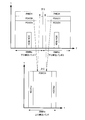
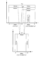
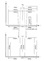
- FIG. 1 and FIG. 2 are diagrams showing an arrangement example of each channel in the LTE + system in which the communication bandwidth (the number of unit bands) is asymmetrical between uplink and downlink.
- the communication bandwidth of the LTE + system is 40 MHz for the downlink and includes two downlink component bands, and 20 MHz for the uplink and includes one uplink component band.
- PHICHs and PDCCHs are distributed and disposed throughout the downlink component bands 1 and 2 respectively.
- SCHs that can be received by LTE terminals and LTE + terminals (hereinafter simply referred to as SCH)
- BCHs that can be received by LTE terminals and LTE + terminals (hereinafter referred to simply as BCHs) are arranged near the center frequency of downlink component bands 1 and 2, respectively. Ru.
- uplink data channels Physical Uplink Shared Channel: PUSCH
- PUSCH Physical Uplink Shared Channel
- downlink component bands 1 and 2 are associated with one uplink component band. For example, when communication is performed using only one unit band, the same uplink component band is used as the uplink, regardless of which of two different downlink component bands 1 and 2 is used as the downlink.
- the LTE + base station is allocated to the PUSCH, assigns a response signal to uplink data transmitted and is assigned to the PHICH, and feeds it back to the terminal.
- a PHICH resource number indicating a resource position of the PHICH is defined in association with a PUSCH resource block (RB) number. That is, the PHICH resource numbers of the PHICHs of the downlink component bands 1 and 2 shown in FIG. 1 are associated with the PUSCH RB numbers.
- each terminal receives the response signal assigned to the PHICH arranged in the same downlink component band as the PDCCH to which the resource assignment information for that terminal is assigned. Then, the terminal calculates the PHICH resource number of the PHICH to which the response signal to the uplink data is allocated, from the RB number of the PUSCH to which the uplink data is allocated. For example, as shown in FIG. 1, when the resource allocation information for the own terminal is allocated to the PDCCH arranged in downlink component band 1, the terminal is a response signal allocated to the PHICH arranged in downlink component band 1. Receive On the other hand, as shown in FIG. 1, when the resource allocation information for the own terminal is allocated to the PDCCH arranged in downlink component band 2, the terminal is a response signal allocated to the PHICH arranged in downlink component band 2. Receive
- PHICH and PDCCH are allocated to only one downlink component band.
- a downlink is a downlink component band (hereinafter referred to as “LTE / LTE + coexistence band”) with which both LTE terminals and LTE + terminals can communicate and a downlink component band with which only LTE + terminals can communicate (hereinafter “LTE + Band)).
- the SCH / BCH is arranged in the LTE / LTE + coexistence band, and in the LTE / LTE + coexistence band, both the LTE terminal and the LTE + terminal can be connected to the LTE + base station.
- SCHs / BCHs that can be received by the LTE terminals are not arranged, but downlink data channels (Physical Downlink Shared Channel: PDSCH) are arranged.
- PDSCH Physical Downlink Shared Channel
- the LTE terminal and the LTE + terminal receive the resource allocation information allocated to the PDCCH allocated to the LTE / LTE + coexistence band, and receive the response signal allocated to the PHICH allocated to the LTE / LTE + coexistence band.
- the second type LTE + terminals that can communicate using multiple component bands are placed in the LTE / LTE + coexistence band even when both the LTE / LTE + coexistence band and the LTE + band shown in FIG. 2 are used.
- the arrangement of the PHICH and the PDCCH may deteriorate the frequency utilization efficiency.
- An object of the present invention is to provide a base station, a terminal, and a channel assignment method capable of improving frequency utilization efficiency in the case where communication bandwidths in the uplink and downlink are asymmetric.
- a base station is a radio communication base station apparatus capable of communication using a plurality of downlink component bands and a smaller number of uplink component bands than the plurality of downlink component bands, and the plurality of downlink component bands Resource allocation information is allocated to each of the first channels allocated, and a response signal for uplink data is a second channel allocated to a part of downlink component bands equal to the uplink component bands among the plurality of downlink component bands And transmission means for transmitting the resource allocation information or the response signal.
- a terminal is a radio communication terminal apparatus capable of communicating using a plurality of downlink component bands and a smaller number of uplink component bands than the plurality of downlink component bands, and the terminals are respectively allocated to the plurality of downlink component bands
- Acquisition means for acquiring resource allocation information addressed to the own apparatus allocated to the first channel, mapping means for mapping uplink data to the uplink component band according to the resource allocation information of uplink data, and
- An extracting means for extracting a response signal from a second channel arranged in a part of downlink component bands equal in number to the uplink component band among the plurality of downlink component bands is adopted.
- the wireless communication base station apparatus capable of performing communication using a plurality of downlink component bands and a smaller number of uplink component bands than the plurality of downlink component bands is used as a second response signal to uplink data.
- a channel assignment method for assigning a channel comprising: assigning resource assignment information to a first channel respectively assigned to the plurality of downlink component bands; and transmitting a response signal to the uplink data to the uplink among the plurality of downlink component bands It allocates to the 2nd channel arrange
- the present invention it is possible to improve frequency utilization efficiency when the communication bandwidth is asymmetric between the uplink and the downlink.
- FIG. 1 Diagram showing an example of arrangement of PHICH and PDCCH in LTE + system Diagram showing an example of arrangement of PHICH and PDCCH in LTE + system Block diagram showing configuration of terminal according to Embodiment 1 of the present invention Block diagram showing configuration of base station according to Embodiment 1 of the present invention A diagram showing an example of arrangement of PHICH and PDCCH according to Embodiment 1 of the present invention A diagram showing an example of arrangement of PHICHs and PDCCHs according to Embodiment 2 of the present invention Block diagram showing configuration of terminal according to Embodiment 3 of the present invention Block diagram showing configuration of a base station according to Embodiment 3 of the present invention A diagram showing an example of arrangement of PHICHs and PDCCHs according to Embodiment 3 of the present invention The figure which shows the component band which the base station which concerns on this Embodiment 5 manages. A diagram showing an example of PHICH and PDCCH arrangement according to the fifth embodiment A diagram showing an example of arrangement of PHICH and PDCCH according to
- the LTE terminal can only communicate in the LTE / LTE + coexistence band in which the SCH and BCH are arranged after recognizing the above-mentioned problems, whereas the second type LTE + terminal can communicate in the LTE / LTE + coexistence band and the LTE + band It is noted that communication can be performed using both downlink component bands. That is, in the LTE / LTE + coexistence band, all terminals supported by the LTE + system can read information.
- PDCCH and PHICH are respectively allocated according to uplink resources or downlink resources.
- uplink resource allocation information indicating the uplink resource (for example, PUSCH) to which uplink data of the terminal is allocated, and downlink resource allocation information indicating the downlink resource (for example, PDSCH) to which downlink data for the terminal are allocated It is allocated to PDCCH and notified to each terminal. Therefore, PDCCH needs to be allocated according to the resource amount of both uplink resource and downlink resource.
- PHICH PHICH resource number
- PUSCH PUSCH RB number
- PHICHs need to be allocated according to the number of PUSCH RBs. That is, the PHICH may be allocated according to only the resource amount of the uplink resource.
- the LTE + base station allocates uplink data and downlink data resource allocation information to PDCCHs allocated to each of a plurality of downlink component bands, and transmits uplink signal response signals to a plurality of downlink units.
- PDCCHs allocated to each of a plurality of downlink component bands
- uplink signal response signals to a plurality of downlink units.
- the bands it is allocated to PHICHs arranged in some downlink component bands (LTE / LTE + coexistence bands) as many as uplink component bands.
- the second type LTE + terminal maps uplink data to the uplink component band according to the resource allocation information addressed to the own terminal allocated to the PDCCH respectively arranged in the plurality of downlink component bands, and a response signal to the uplink data Are extracted from a plurality of downlink component bands from the PHICH arranged in the same number of downlink component bands (LTE / LTE + coexistence band) as the uplink component bands.
- FIG. 3 is a block diagram showing a configuration of terminal 100 according to the present embodiment.
- the terminal 100 is a second type LTE + terminal, and can communicate using a plurality of downlink component bands simultaneously.
- the reception RF unit 102 is configured to be able to change the reception band.
- the reception RF unit 102 performs reception radio processing (down conversion, analog-to-digital (A / D) conversion, etc.) on the reception radio signal (in this case, OFDM signal) received in the reception band via the antenna 101.
- the received signal is output to CP (Cyclic Prefix) removing section 103.
- CP removing section 103 removes the CP from the received signal
- FFT (Fast Fourier Transform) section 104 converts the received signal after CP removal into a frequency domain signal. This frequency domain signal is output to the frame synchronization unit 105.
- the frame synchronization unit 105 searches for the SCH contained in the signal input from the FFT unit 104 and synchronizes (frame synchronization) with a base station 200 described later. Also, frame synchronization section 105 acquires a cell ID associated with a sequence (SCH sequence) used for SCH. That is, in the frame synchronization unit 105, processing similar to that of a normal cell search is performed. Then, the frame synchronization unit 105 outputs frame synchronization timing information indicating frame synchronization timing, and a signal input from the FFT unit 104 to the separation unit 106.
- Demultiplexing section 106 is configured to receive the BCH, the response signal (that is, the PHICH signal), and the control signal (that is, the PDCCH signal) based on the frame synchronization timing information input from frame synchronization section 105. And the data signal (ie, PDSCH signal).
- separation section 106 separates the response signal for the uplink data of the own terminal according to the downlink component band and PHICH resource number indicated in the resource control information input from resource control section 108. Extract from PHICH signal.
- demultiplexing section 106 is a part of downlink component bands equal to uplink component bands among a plurality of downlink component bands as a response signal to uplink data of the own terminal, and SCH / BCH is arranged. It extracts from PHICH arranged in the LTE / LTE + coexistence band which is a downlink component band. Then, demultiplexing section 106 outputs BCH to broadcast information receiving section 107, outputs the PHICH signal to PHICH receiving section 109, outputs the PDCCH signal to PDCCH receiving section 110, and outputs the PDSCH signal to PDSCH receiving section 111.
- the broadcast information receiving unit 107 reads the contents of the BCH input from the separating unit 106, and acquires the association between the PUSCH RB number and the PHICH resource number and the PHICH resource information indicating the number of PHICH resources. Then, broadcast information receiving section 107 outputs PHICH resource information to resource control section 108.
- resource control section 108 Based on the PHICH resource information input from broadcast information receiving section 107 and the uplink resource allocation information input from PDCCH receiving section 110, resource control section 108 assigns a PHICH to which a response signal to uplink data of the own terminal is allocated. Identify.
- the PHICH is arranged in part of downlink component bands among a plurality of downlink component bands. Therefore, the resource control unit 108 identifies the downlink component band in which the PHICH is allocated, based on the PHICH resource information. Furthermore, based on the uplink resource allocation information, resource control section 108 specifies the PHICH resource number of PHICH associated with the RB number of PUSCH used for transmitting uplink data of the own terminal. Then, the resource control unit 108 outputs resource control information indicating the identified downlink component band and the PHICH resource number of the PHICH to the separation unit 106.
- PHICH receiving section 109 decodes the PHICH signal input from demultiplexing section 106, and outputs a response signal (ACK signal or NACK signal) that is the decoding result to retransmission control section 112.
- the PDCCH receiving unit 110 performs blind decoding on the PDCCH signal input from the separating unit 106.
- the PDCCH signals are respectively arranged in a plurality of downlink component bands.
- the PDCCH receiving unit 110 de-masks the CRC bit of the PDCCH signal input from the demultiplexing unit 106 with the terminal ID of the own terminal by using the terminal ID of the own terminal. It determines that it is a signal.
- PDCCH receiving section 110 acquires downlink resource allocation information and uplink resource allocation information included in the PDCCH signal addressed to the own terminal, outputs downlink resource allocation information to PDSCH reception section 111, and frequency-maps uplink resource allocation information. Output to the unit 115 and the resource control unit 108.
- the PDSCH receiving unit 111 extracts received data from the PDSCH signal input from the separating unit 106 based on the downlink resource allocation information input from the PDCCH receiving unit 110.
- the retransmission control unit 112 controls retransmission of transmission data in response to the response signal (ACK signal or NACK signal) input from the PHICH receiving unit 109. Specifically, when the ACK signal from base station 200 is input from PHICH receiving section 109, retransmission control section 112 instructs modulation section 113 to modulate new transmission data. On the other hand, when the NACK signal from base station 200 is input from PHICH receiving section 109, that is, at the time of retransmission, retransmission control section 112 modulates the modulation section to modulate transmission data (retransmission data) corresponding to the NACK signal. Direct to 113.
- Modulating section 113 modulates transmission data (new transmission data or retransmission data) according to an instruction from retransmission control section 112, and outputs the obtained modulated signal to DFT (Discrete Fourier transform) section 114.
- DFT Discrete Fourier transform
- the DFT unit 114 converts the modulation signal input from the modulation unit 113 into a frequency domain, and outputs a plurality of obtained frequency components to the frequency mapping unit 115.
- the frequency mapping unit 115 maps the plurality of frequency components input from the DFT unit 114 to the PUSCH allocated to the uplink component band in accordance with the uplink resource allocation information input from the PDCCH receiving unit 110.
- An IFFT (Inverse Fast Fourier Transform) unit 116 converts a plurality of mapped frequency components into a time domain waveform, and a CP adding unit 117 adds a CP to the time domain waveform.
- IFFT Inverse Fast Fourier Transform
- the transmission RF unit 118 performs transmission radio processing (up conversion, digital analog (A / D) conversion, etc.) on the signal to which the CP is added, and transmits the signal via the antenna 101.
- transmission radio processing up conversion, digital analog (A / D) conversion, etc.
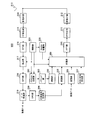
- FIG. 4 is a block diagram showing a configuration of base station 200 according to the present embodiment.
- Base station 200 is an LTE + base station.
- Control section 201 generates uplink resource allocation information and downlink resource allocation information, outputs uplink resource allocation information to PDCCH generation section 202 and extraction section 217, and outputs downlink resource allocation information to PDCCH generation section 202 and multiplexing section 209. Do.
- the control unit 201 allocates uplink resource allocation information and downlink resource allocation information to PDCCHs respectively arranged in a plurality of downlink component bands.
- control unit 201 assigns a response signal to uplink data to the PHICHs arranged in some downlink component bands equal in number to the uplink component bands among a plurality of downlink component bands. Specifically, regardless of whether the transmission source terminal of uplink data is an LTE terminal or an LTE + terminal, the control unit 201 transmits a response signal for uplink data to the LTE / N of the plurality of downlink component bands. Allocate the PHICH allocated to the LTE + coexistence band. Further, control section 201 specifies a PHICH resource number associated with the RB number of PUSCH to which uplink data from the terminal is allocated.
- control section 201 generates PHICH resource information indicating a downlink component band to which a response signal to uplink data of that terminal is to be allocated and a PHICH resource number, and outputs PHICH resource information to PHICH allocation section 208.
- the PDCCH generation unit 202 generates a PDCCH signal including uplink resource allocation information and downlink resource allocation information input from the control unit 201. Further, the PDCCH generation unit 202 adds a CRC bit to the PDCCH signal to which the uplink resource allocation information and the downlink resource allocation information are allocated, and further masks the CRC bit by the terminal ID. Then, the PDCCH generation unit 202 outputs the masked PDCCH signal to the modulation unit 203.
- the modulation unit 203 modulates the PDCCH signal input from the PDCCH generation unit 202, and outputs the modulated PDCCH signal to the multiplexing unit 209.
- a NACK signal is generated as a response signal.
- the response signal generation unit 204 outputs the generated response signal (ACK signal or NACK signal) to the modulation unit 205.
- Modulating section 205 modulates the response signal inputted from response signal generating section 204, and outputs the modulated response signal to multiplexing section 209.
- Modulating section 206 modulates the input transmission data (downlink data), and outputs the modulated transmission data signal to multiplexing section 209.
- SCH / BCH generating section 207 generates SCH and BCH, and outputs the generated SCH and BCH to multiplexing section 209.
- PHICH arranging section 208 determines the PHICH to be allocated to each downlink component band. Specifically, PHICH arranging section 208 is a PHICH arranged in the downlink component band indicated in PHICH resource information, and arranges the PHICH corresponding to the PHICH resource number indicated in PHICH resource information in each downlink component band. Determined as the PHICH to be Then, PHICH arranging section 208 outputs, to multiplexing section 209, allocation information indicating the determined PHICH allocation.
- Multiplexing section 209 includes a PDCCH signal input from modulation section 203, a response signal (that is, PHICH signal) input from modulation section 205, a data signal (that is, PDSCH signal) input from modulation section 206, and SCH / BCH.
- the SCH and BCH input from the generation unit 207 are multiplexed.
- multiplexing section 209 maps the data signal (PDSCH signal) to the downlink component band based on the downlink resource information input from control section 201, and based on the allocation information input from PHICH allocation section 208,
- the response signal (PHICH signal) is mapped to the downlink component band.
- the IFFT unit 210 converts the multiplexed signal into a time waveform, and the CP addition unit 211 obtains an OFDM signal by adding a CP to this time waveform.
- the transmission RF unit 212 performs transmission radio processing (up-conversion, digital analog (A / D) conversion, etc.) on the OFDM signal input from the CP addition unit 211, and transmits it via the antenna 213.
- transmission radio processing up-conversion, digital analog (A / D) conversion, etc.
- reception RF section 214 performs reception radio processing (down conversion, analog-digital (A / D) conversion, etc.) on the reception radio signal received in the reception band via antenna 213, and obtains the obtained reception signal Output to CP removing section 215.
- reception radio processing down conversion, analog-digital (A / D) conversion, etc.
- CP removing section 215 removes the CP from the received signal, and FFT section 216 converts the received signal after CP removal into a frequency domain signal.
- the extracting unit 217 extracts uplink data from the frequency domain signal input from the FFT unit 216 based on the uplink resource allocation information input from the control unit 201, and an IDFT (Inverse Discrete Fourier Transform) unit 218 extracts the extracted signal. Is converted to a time domain signal, and the time domain signal is output to the data receiving unit 219.
- IDFT Inverse Discrete Fourier Transform
- the data reception unit 219 decodes the time domain signal input from the IDFT unit 218. Then, the data reception unit 219 outputs the decoded uplink data as reception data and outputs the uplink data to the CRC unit 220.
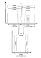
- the base station 200 transmits the PHICH and PDCCH in the frequency allocation as shown in the upper part of FIG.
- base station 200 can communicate using two downlink component bands (LTE / LTE + coexistence band and LTE + band) and one uplink component band (LTE / LTE + coexistence band).
- the PDCCHs are respectively arranged in two downlink component bands.
- PHICH is allocated to only part of downlink component bands of the same number (ie, one) as uplink component bands among two downlink component bands. Specifically, as shown in the upper part of FIG.
- the PHICH is arranged in the LTE / LTE + coexistence band in which both the LTE terminal and the LTE + terminal can communicate. That is, PHICH is allocated to the LTE / LTE + coexistence band in which SCH and BCH are allocated.
- the BCH includes information on the number of OFDM symbols in which the PHICH is allocated, and information on the number of PHICH resources.
- the number of OFDM symbols in which the PHICH is allocated is two, one symbol and three symbols. Therefore, the OFDM symbol in which the PHICH is allocated is included in the BCH as 1-bit information.
- the number of PHICH resources is notified in association with the number of RBs included in the downlink component band. Specifically, the number of PHICH resources is one of twice, one, one half and one quarter of the number of RBs included in the downlink component band.
- terminal 100 and base station 200 are associated with the RB of the smallest RB number among the plurality of RBs used for uplink data transmission. It is determined that a response signal has been assigned to PHICH.
- the base station 200 (LTE + base station) and the terminal 100 (second type LTE + terminal) communicate will be described.
- control unit 201 of the base station 200 transmits uplink resource allocation information and downlink resource allocation information to be notified to the terminal 100 to any one of the LTE / LTE + coexistence band and the PDCCH arranged in the LTE + band shown in the upper stage of FIG. assign.
- Demultiplexing section 106 of terminal 100 decouples PDCCH signals arranged respectively in the LTE / LTE + coexistence band and LTE + band shown in the upper part of FIG. 5 from the received signals, and PDCCH receiving section 110 addresses the own terminal from the despread PDCCH signals.
- Resource allocation information uplink resource allocation information and downlink resource allocation information
- the frequency mapping unit 115 of the terminal 100 maps the transmission data (uplink data) to the PUSCH arranged in the uplink component band (LTE / LTE + coexistence band) shown in the lower part of FIG. 5 according to the acquired uplink resource allocation information. .
- response signal generation section 204 of base station 200 generates a response signal (ACK signal or NACK signal) for uplink data from terminal 100. Further, control section 201 of base station 200 allocates a response signal to uplink data from terminal 100 to the PHICH arranged in the LTE / LTE + coexistence band shown in the upper stage of FIG. 5.
- the control unit 201 identifies the PHICH of the PHICH resource number associated with the RB number of the PUSCH assigned to the uplink data among the PHICHs arranged in the LTE / LTE + coexistence band shown in the upper part of FIG.
- the control unit 201 of the base station 200 is the PDCCH in which the PDCCH to which the uplink resource allocation information addressed to the terminal 100 is allocated is either the LTE / LTE + coexistence band or the LTE + band , Assign a response signal to the PHICH arranged in the LTE / LTE + coexistence band.
- the control unit 201 responds to uplink data transmitted according to the resource allocation information.
- a signal is allocated to the PHICH arranged in the LTE / LTE + coexistence band.
- resource control section 108 of terminal 100 selects an LTE / LTE + coexistence band among the two downlink component bands as the downlink component band to which a response signal to uplink data is assigned. That is, as shown in FIG. 5, even if the PDCCH to which the resource allocation information for the own terminal is allocated is a PDCCH allocated to either the LTE / LTE + coexistence band or the LTE + band, the resource control unit 108 is a base station Similar to the control unit 201 of 200, control is performed to extract a response signal to uplink data from the PHICH arranged in the LTE / LTE + coexistence band.
- the resource control unit 108 calculates the PHICH resource number of the PHICH associated with the RB number of the PUSCH to which the uplink data is mapped. Then, demultiplexing section 106 is a PHICH arranged in the downlink component band (LTE / LTE + coexistence band) selected by resource control section 108 for the response signal to uplink data, and the PHICH resource number calculated by resource control section 108 Extract from PHICH.
- LTE / LTE + coexistence band the downlink component band
- the base station 200 (LTE + base station) communicates with a terminal that can communicate using only one component band, that is, an LTE terminal or a first type LTE + terminal
- the LTE terminal and the first type LTE + terminal are LTE / / Accommodate in LTE + coexistence band. Therefore, the LTE terminal or the first type LTE + terminal receives the resource allocation information allocated to the PDCCH arranged in the LTE / LTE + coexistence band, and transmits uplink data (PUSCH signal) to the base station 200 according to the resource allocation information. Send. Then, the LTE terminal or the first type LTE + terminal extracts a response signal to uplink data from the PHICH arranged in the LTE / LTE + coexistence band. That is, the LTE terminal or the first type LTE + terminal always communicates with the base station 200 using the LTE / LTE + coexistence band.
- a downlink component band in which SCH and BCH are arranged that is, a downlink component band in which both an LTE terminal and an LTE + terminal can communicate is a part of downlinks in which PHICH is allocated. It was a unit band.
- all terminals (LTE terminals, type 1 LTE + terminals and type 2 LTE + terminals (terminal 100)) supported by the LTE + terminals (base station 200) are allocated to the PHICH arranged in the LTE / LTE + coexistence band Receive the received response signal. That is, all terminals supported by the LTE + system can receive the same PHICH.
- the overhead of the PHICH can be suppressed. Furthermore, in the LTE + band, the arrangement of PHICHs becomes unnecessary, so more PDSCHs can be arranged, and frequency utilization efficiency can be improved.
- PDCCHs are arranged in both the LTE / LTE + coexistence band and the LTE + band. For this reason, in the base station 200, by using the PDCCHs allocated to the downlink component bands, the PDSCHs allocated to the two downlink component bands and the PUSCH allocated to the one uplink component band can be efficiently transmitted to each terminal. It becomes possible to allocate.
- the LTE + base station allocates uplink resource allocation information and downlink resource allocation information to PDCCHs respectively arranged in a plurality of downlink component bands, and transmits a response signal to uplink data, Of the plurality of downlink component bands, it is allocated to PHICHs arranged in the same number of downlink component bands as uplink component bands.
- the PHICH and PDCCH required for the LTE terminal and the LTE + terminal can be transmitted in an arrangement with high frequency utilization efficiency. Therefore, according to the present embodiment, it is possible to improve frequency utilization efficiency when the communication bandwidth is asymmetric between the uplink and the downlink.
- Second Embodiment a case where a first type LTE + terminal communicates in the LTE + band will be described.
- the basic configurations of the terminal and the base station according to the present embodiment are the same as the configurations of the terminal and the base station described in the first embodiment. Therefore, the terminal according to the present embodiment will also be described using FIGS. 3 and 4.
- Base station 200 transmits PHICH and PDCCH in the frequency allocation as shown in the upper part of FIG.
- base station 200 includes two downlink component bands (LTE / LTE + coexistence band and LTE + band) and one uplink component band (LTE / LTE + coexistence band) as in FIG. 5 of the first embodiment. It is possible to communicate using.
- the PHICH is allocated to the downlink component bands of both the LTE / LTE + coexistence band and the LTE + band.
- the resource amount of PHICH arranged in the LTE / LTE + coexistence band is larger than the resource amount of PHICH arranged in the LTE + band.
- the resource amount of the PHICH arranged in the LTE / LTE + coexistence band is the same as that of the first embodiment (upper part of FIG. 5)
- the resource amount of the PHICH arranged in the LTE + band is LTE / This is smaller than the amount of PHICH resources allocated to the LTE + coexistence band.
- the resource amount of PHICH arranged in the LTE + band is associated in advance with the resource amount of PHICH arranged in the LTE / LTE + coexistence band.
- the resource amount of the PHICH allocated to the LTE + band is 1 ⁇ 2 of the resource amount of the PHICH allocated to the LTE / LTE + coexistence band.
- PDCCHs are respectively arranged in two downlink component bands, and SCH / BCH are arranged only in LTE / LTE + coexistence bands.
- each terminal receives the response signal assigned to the PHICH arranged in the LTE / LTE + coexistence band shown in the upper part of FIG. 6
- the base station 200 (LTE + base station) communicates with the first type LTE + terminal accommodated in the LTE + band shown in the upper part of FIG. 6 will be described below.
- First-class LTE + terminals (that is, terminals that can communicate using only one component band) are first accommodated in the LTE / LTE + coexistence band and receive the SCH / BCH arranged in the LTE / LTE + coexistence band It connects with the base station 200. Then, the base station 200 instructs the first type LTE + terminal to move from the LTE / LTE + coexistence band to the LTE + band, and the first type LTE + terminal is moved to the LTE + band according to the instruction from the base station 200. Moving. Thereby, the first type LTE + terminal is accommodated in the LTE + band.
- the first type LTE + terminal acquires PHICH resource information (for example, an OFDM symbol in which PHICH is allocated, the number of PHICH resources) indicated in LTE / LTE + coexistence band indicated in BCH arranged in LTE / LTE + coexistence band Do. Then, the first type LTE + terminal calculates resource information of the PHICH arranged in the LTE + band based on the association between the PHICH arranged in the LTE / LTE + coexistence band and the PHICH arranged in the LTE + band. For example, the first type LTE + terminal calculates 1 ⁇ 2 of the number of PHICH resources arranged in the LTE / LTE + coexistence band as the number of PHICH resources arranged in the LTE + band.
- PHICH resource information for example, an OFDM symbol in which PHICH is allocated, the number of PHICH resources
- the first type LTE + terminal receives the resource allocation information allocated to the PDCCH arranged in the LTE + band shown in the upper part of FIG. 6, and transmits uplink data (PUSCH signal) to the base station 200 according to the resource allocation information Do.
- PUSCH signal uplink data
- the control unit 201 of the base station 200 controls a response signal to uplink data from the first type LTE + terminal to be assigned to the PHICH arranged in the LTE + band among the two downlink component bands shown in the upper stage of FIG. . That is, as shown in FIG. 6, the base station 200 allocates the response signal to the uplink data of the first type LTE + terminal accommodated in the LTE + band to the PHICH arranged in the LTE + band. Further, like the base station 200, the first type LTE + terminal extracts a response signal to uplink data from the PHICH arranged in the LTE + band.
- the first type LTE + terminal can be accommodated in the LTE + band. Therefore, in the first type LTE + terminal, when the terminal is accommodated in the LTE + band, the response signal allocated to the PHICH arranged in the LTE + band is received.
- the LTE terminal and the second type LTE + terminal receive the PHICH arranged in the LTE / LTE + coexistence band as in the first embodiment. That is, the PHICH arranged in the LTE + band is used only for the first type LTE + terminal accommodated in the LTE + band.
- the PHICH arranged in the LTE + band is associated with the same PUSCH as the PUSCH associated with the PHICH arranged in the LTE / LTE + coexistence band.
- the resource amount of the PHICH arranged in the LTE + band is smaller than the resource amount of the PHICH arranged in the LTE / LTE + coexistence band, the overhead of the PHICH in the LTE + band can be suppressed.
- the first type LTE + terminal calculates the PHICH resource information of the LTE + band based on the PHICH resource information of the LTE / LTE + coexistence band. As a result, in the base station, the signaling of the PHICH resource information in the LTE + band becomes unnecessary, so that the frequency utilization efficiency can be further improved.
- the resource information of PHICH arranged in the LTE + band is associated with the resource information of PHICH arranged in the LTE / LTE + coexistence band.
- the resource information of the PHICH arranged in the LTE + band may be notified using the BCH in the LTE / LTE + coexistence band, or individually to the first type LTE + terminal accommodated in the LTE + band. It may be notified.
- the second type LTE + terminal SCH / BCH is arranged among a plurality of downlink component bands regardless of the downlink component band that has received PDCCH, as in the first embodiment.
- the case of selecting the PHICH arranged in the downlink component band (LTE / LTE + coexistence band) has been described.
- the second type LTE + terminal may be separately instructed from the LTE + base station as to which downlink component band of the LTE / LTE + coexistence band and the LTE + band to select the PHICH arranged in.
- the second type LTE + terminal can specify the downlink component band in which the PHICH to which the response signal is allocated is allocated, so the present invention The same effect can be obtained.
- the PHICH resource is arranged only in one of the unit bands.
- uplink resource allocation information of uplink data is transmitted to terminals by PDCCH only from a part of downlink component bands in which PHICH resources are allocated.
- the downlink resource allocation information and the uplink resource allocation information of the downlink component band in which the PHICH resources are allocated have the same information size (that is, the number of bits required for transmission).
- the PDCCH signal includes type information (for example, a 1-bit flag) of resource allocation information. Therefore, even if the size of the PDCCH signal including downlink resource allocation information and the PDCCH signal including uplink resource allocation information is the same, the terminal checks downlink resource allocation information or uplink resource by confirming the type information of the resource allocation information. It can distinguish whether it is allocation information.
- the PDCCH format when uplink resource allocation information is transmitted is PDCCH format 0, and the PDCCH format when downlink resource allocation information is transmitted is PDCCH format 1A.
- the information size is different between the downlink resource allocation information and the uplink resource allocation information.
- the information size of downlink resource allocation information and the information size of uplink resource allocation information are different due to the difference in bandwidth as described above, allocation is made to PDCCHs of some downlink component bands.
- the information size of the downlink resource allocation information and the information size of the uplink resource allocation information are equalized by adding zero information (zero padding (0 Padding)) to the resource allocation information to be stored. Thereby, the identity of the size of the PDCCH signal is maintained regardless of the downlink resource allocation information or the uplink resource allocation information.
- FIG. 7 is a block diagram showing a configuration of terminal 800 according to Embodiment 3 of the present invention.
- a terminal 800 shown in FIG. 7 adds a format determination unit 803 to the terminal 100 according to the first embodiment shown in FIG. 3, and has a PDCCH reception unit 802 instead of the PDCCH reception unit 110, and receives broadcast information
- a broadcast information receiving unit 801 is provided instead of the unit 107.
- parts that are the same as in FIG. 3 are given the same reference numerals, and descriptions thereof will be omitted.
- Demultiplexing section 106 is configured to receive the BCH, the response signal (that is, the PHICH signal), and the control signal (that is, the PDCCH signal) based on the frame synchronization timing information input from frame synchronization section 105. And the data signal (ie, PDSCH signal).
- separation section 106 separates the response signal for the uplink data of the own terminal according to the downlink component band and PHICH resource number indicated in the resource control information input from resource control section 108. Extract from PHICH signal.
- demultiplexing section 106 is a part of downlink component bands equal to uplink component bands among a plurality of downlink component bands as a response signal to uplink data of the own terminal, and SCH / BCH is arranged. It extracts from PHICH arranged in the LTE / LTE + coexistence band which is a downlink component band. Then, demultiplexing section 106 outputs BCH to broadcast information receiving section 801, outputs a PHICH signal to PHICH receiving section 109, outputs a PDCCH signal to PDCCH receiving section 802, and outputs a PDSCH signal to PDSCH receiving section 111.
- the broadcast information receiving unit 801 reads the content of the BCH input from the separating unit 106, and acquires the association between the PUSCH RB number and the PHICH resource number and the PHICH resource information indicating the number of PHICH resources. Then, broadcast information receiving section 801 outputs PHICH resource information to resource control section 108. Also, broadcast information receiving section 801 reads the contents of BCH input from demultiplexing section 106, and acquires BCH information on the configuration of the downlink component band and uplink component band of base station 900 described later.
- the broadcast information receiving unit 801 acquires, for example, the number of uplink component bands, the number of downlink component bands, identification numbers and bandwidths of each component band, association information between uplink component bands and downlink component bands, basic component band information, etc. Do.
- the basic unit band can be obtained from the bandwidth of the uplink component band and the bandwidth of the downlink component band, here, the base station 900 includes identification information of the basic component band in the BCH. Then, broadcast information receiving section 801 outputs the acquired BCH information to format determination section 803 and PDCCH receiving section 802.
- the PDCCH receiving unit 802 uses the information size of resource allocation information corresponding to the bandwidth of each downlink component band, the information size of resource allocation information corresponding to the bandwidth of the uplink component band, and the terminal ID of its own device. It blind-decodes the PDCCH signal of each downlink component band input from demultiplexing section 106.
- the PDCCH signals are respectively arranged in a plurality of downlink component bands.
- the PDCCH receiving unit 802 first specifies a CRC bit equivalent portion included in each PDCCH signal. At this time, in the base station 900, adjustment of the information size may be performed by zero padding. Therefore, in the PDCCH signal of the basic component band, the PDCCH receiving unit 802 determines the information size (payload size: Payload) obtained from the bandwidth of the basic component band and the bandwidth of the uplink component band corresponding to the wider bandwidth. Use size) to identify the CRC bit equivalent part.
- downlink component bands other than the basic component band only include downlink resource allocation information.
- the format determination unit 803 determines whether the format of the PDCCH signal is format 0 or format 1 A based on the type information of resource allocation information included in the PDCCH signal received from the PDCCH reception unit 802. If the format determination unit 803 determines that the format is format 0, the format determination unit 803 outputs uplink resource allocation information included in the PDCCH signal to the frequency mapping unit 115 and the resource control unit 108. Also, if the format determination unit 803 determines that the format is format 1A, the format determination unit 803 outputs downlink resource allocation information included in the PDCCH signal to the PDSCH reception unit 111.
- the format determination unit 803 determines that the format is 0 in a component band in which no PHICH resource is allocated. There is nothing to do.
- resource control section 108 Based on the PHICH resource information input from broadcast information receiving section 801 and the uplink resource allocation information input from format determination section 803, resource control section 108 assigns a PHICH to which a response signal to uplink data of the own terminal is allocated. Identify.
- the PHICH is arranged in part of downlink component bands among a plurality of downlink component bands. Therefore, the resource control unit 108 identifies the downlink component band in which the PHICH is allocated, based on the PHICH resource information. Furthermore, based on the uplink resource allocation information, resource control section 108 specifies the PHICH resource number of PHICH associated with the RB number of PUSCH used for transmitting uplink data of the own terminal. Then, the resource control unit 108 outputs resource control information indicating the identified downlink component band and the PHICH resource number of the PHICH to the separation unit 106.
- the PDSCH receiving unit 111 extracts received data from the PDSCH signal input from the separating unit 106 based on the downlink resource allocation information input from the format determining unit 803.
- the frequency mapping unit 115 maps the plurality of frequency components input from the DFT unit 114 to the PUSCH arranged in the uplink component band according to the uplink resource allocation information input from the format determination unit 803.
- FIG. 8 is a block diagram showing a configuration of base station 900 according to Embodiment 3 of the present invention.
- a base station 900 shown in FIG. 8 adds a padding unit 903 to the base station 200 according to the first embodiment shown in FIG. 4 and has a control unit 901 instead of the control unit 201, and a PDCCH generation unit 202 Instead of the PDCCH generation unit 902.
- symbol is attached
- Control section 901 generates uplink resource allocation information and downlink resource allocation information, outputs uplink resource allocation information to PDCCH generation section 902 and extraction section 217, and outputs downlink resource allocation information to PDCCH generation section 902 and multiplexing section 209. Do. While allocating downlink resource allocation information to all of the plurality of downlink component bands, the control unit 901 allocates uplink resource allocation information to only a part of the plurality of downlink component bands.
- uplink resource allocation information is allocated to a downlink component band having a bandwidth closest to the bandwidth of the uplink component band among a plurality of downlink component bands associated with one uplink component band.
- the allocation target downlink component band to which uplink resource allocation information is allocated may be referred to as a “basic component band”.
- the control unit 901 outputs the uplink resource allocation information and the downlink resource allocation information to the PDCCH generation unit 902, and also, to the PDCCH generation unit 902, information (hereinafter sometimes referred to as “basic unit band information”) related to a basic component band. Output.
- the basic unit band information may be included in the BCH by the SCH / BCH generation unit 207.
- control unit 901 passes bandwidth comparison information indicating the magnitude of the bandwidth of the basic component band and the bandwidth of the uplink component band to the padding unit 903 via the PDCCH generation unit 902.
- control unit 901 assigns a response signal to uplink data to the PHICH arranged in some downlink component bands equal in number to the uplink component bands among a plurality of downlink component bands. Specifically, regardless of whether the transmission source terminal of uplink data is an LTE terminal or an LTE + terminal, the control unit 901 is configured to transmit a response signal for uplink data to the LTE / Allocate the PHICH allocated to the LTE + coexistence band. Also, the control unit 901 identifies the PHICH resource number associated with the PUSCH RB number to which uplink data from the terminal is allocated. Then, control section 901 generates PHICH resource information indicating a downlink component band for allocating a response signal to uplink data of the terminal and a PHICH resource number, and outputs PHICH resource information to PHICH allocation section 208.
- the PDCCH generation unit 902 generates a PDCCH signal including uplink resource allocation information and downlink resource allocation information input from the control unit 901. At this time, the PDCCH generation unit 902 includes uplink resource allocation information and downlink resource allocation information in the PDCCH signal allocated to the downlink component band indicated by the basic component band information and PDCCH signals allocated to other downlink component bands. Includes only downlink resource allocation information. Then, the PDCCH generation unit 902 outputs the PDCCH signal to the padding unit 903.
- Padding section 903 adds zero information to the smaller information size until the information sizes of downlink resource allocation information and uplink resource allocation information become equal in the PDCCH signal input from PDCCH generation section 902 (zero padding). At this time, padding section 903 is arranged in the downlink component band in which PHICH resources are allocated without adding zero information to the downlink resource allocation information of PDCCHs allocated in downlink component bands in which no PHICH resources are allocated. Zero information is added only to downlink resource allocation information or uplink resource allocation information of the PDCCH. Also, the padding section 903 determines which of the downlink resource allocation information and the uplink resource allocation information the zero information is to be added based on the bandwidth comparison information.
- padding section 903 adds a CRC bit to the PDCCH signal to which the uplink resource allocation information and the downlink resource allocation information are allocated, and further masks the CRC bit with the terminal ID. Then, padding section 903 outputs the PDCCH signal to which CRC bits have been added to modulation section 203.
- Modulating section 203 modulates the PDCCH signal input from padding section 903, and outputs the modulated PDCCH signal to multiplexing section 209.
- FIG. 9 is a diagram illustrating an exemplary arrangement of PHICH and PDCCH.
- Base station 900 allocates PHICH resources to only a part of component bands in a plurality of downlink component bands, and allocates uplink resource uplink resource data using PDCCH only from part of the component bands to which PHICH resources are allocated. Send information That is, the base station 900 does not use PDCCH resources for transmitting uplink resource allocation information of uplink data in a unit band in which no PHICH resources are allocated.
- terminal 800 blind-decodes the PDCCH signal input from demultiplexing section 106 in PDCCH receiving section 802 as in the above-mentioned first embodiment.
- the size of PDCCH information bits required for blind decoding corresponds to the result of determination as to whether a PHICH resource is allocated in the component band in which the PDCCH is transmitted and to the downlink component band in which the PDCCH resource is transmitted It is determined by the bandwidth of the upstream component band.
- the information size used for blind decoding of PDCCH is determined only by the bandwidth of the downlink component band.
- the information size used for blind decoding of PDCCH is referred to the larger one of the bandwidth of the downlink component band and the bandwidth of the corresponding uplink component band. Decide. Specifically, as the frequency of the component band is smaller, the number of bits required to indicate the frequency position of the allocated channel resource is smaller. For example, when the uplink component band is larger than the downlink component band, downlink data It is determined that “0” is inserted (zero padded) into the downlink resource allocation information of Accordingly, it can be assumed that uplink resource allocation information of uplink data and downlink resource allocation information of downlink data have the same information size.
- uplink resource allocation information of uplink data and the information size of downlink resource allocation information of downlink data become the same by this zero padding, it becomes possible to try blind decoding simultaneously for both terminals. Circuit size can be reduced.
- the information for which the blind decoding has succeeded is uplink resource allocation information of uplink data or downlink resource allocation information of downlink data, 1 bit “uplink / downlink allocation included in information bits”. It can be determined by the information determination flag.
- the importance of downlink control information is generally higher than uplink control information. That is, the downlink control information is used not only for notifying resource allocation information of the downlink data channel, but also for scheduling information of other important information (for example, paging information, broadcast information). Therefore, it is desirable that the frequency of zero padding for downlink control information be reduced.
- the frequency diversity effect that the PDCCH can obtain depends on the bandwidth of the downlink component band. Therefore, in a narrow bandwidth downlink component band, the frequency diversity effect is small, and therefore, it is desirable to eliminate factors that degrade the quality as much as possible. However, with regard to zero padding, the lower bandwidth downlink component band is more likely to be zero padded.
- a method may be considered in which the sizes of uplink control information and downlink control information are made different.
- the terminal side needs to separately blind-decode two control information having different numbers of information bits. Therefore, the problem is that the number of blind decodings increases and the circuit scale increases accordingly.
- the present embodiment only the downlink resource allocation information of downlink data is allocated in the PDCCH arranged in the downlink component band in which no PHICH resource is allocated, and zero padding is not performed. A reduction in power per bit can be suppressed.
- uplink resource allocation information is not transmitted in the downlink component band in which no PHICH resource is allocated. It is possible to avoid the zero padding that is performed to match the information size of the information and the information size of the resource allocation information of uplink data. As a result, unnecessary data transmission is not performed, and the power per information bit that is originally required can be improved.
- the terminal determines whether or not the zero padding is necessary when performing blind decoding depending on whether the PHICH resource exists or not, but the PHICH resource actually exists.
- the SCH and BCH for LTE terminals for accommodating LTE terminals are arranged in the component band to be connected. Therefore, the terminal may determine whether or not zero padding is necessary according to the presence or absence of SCH / BCH for accommodating LTE terminals.
- zero padding is performed by inserting “0” in order to make the information size the same, but the present embodiment is not limited to this, and any redundant bit other than “0” is added.
- the information size may be the same.
- the present embodiment there is no need to determine that the format is 0 in a unit band in which no PHICH resource is allocated, so in a unit band in which no PHICH resource is allocated, type information of resource allocation information included in PDCCH. You can reduce bits. That is, the power efficiency of PDCCH transmission can be improved.
- the type information bit equivalent portion when the type information bit equivalent portion is not reduced, the type information bit equivalent portion of the resource allocation information has a fixed value (that is, type information indicating downlink allocation) in the component band in which the PHICH resource is not allocated. This part can also be used on the terminal side as part of the parity bit.
- Embodiment 4 The present embodiment is different from Embodiment 3 only in that the information sizes of downlink resource allocation information and uplink resource allocation information may differ from each other even when the uplink bandwidth and the downlink bandwidth are the same.
- the downlink resource allocation information and uplink resource allocation information of the downlink component band in which the PHICH resources are allocated have the same information size.
- the information sizes of the downlink resource allocation information and the uplink resource allocation information are approximately equal but not necessarily the same.
- the larger the difference between the uplink bandwidth and the downlink bandwidth the larger the difference in information size between downlink resource allocation information and uplink resource allocation information.
- the basic configurations of the terminal and the base station according to the present embodiment are the same as the configurations of the terminal and the base station described in the third embodiment. Therefore, the terminal and base station according to the present embodiment will also be described using FIG. 7 and FIG.
- PDCCH receiving section 802 of terminal 800 (FIG. 7) according to the present embodiment is the information size of resource allocation information corresponding to the bandwidth of each downlink component band, and the information of resource allocation information corresponding to the bandwidth of uplink component band It blind-decodes the PDCCH signal of each downlink component band input from the separation unit 106 using the size and the terminal ID of the own terminal.
- the PDCCH signals are respectively arranged in a plurality of downlink component bands.
- the PDCCH receiving unit 802 first specifies a CRC bit equivalent portion included in each PDCCH signal. At this time, in the base station 900 (FIG. 8), adjustment of the information size may be performed by zero padding. Therefore, in the PDCCH signal of the basic component band, PDCCH receiving section 802 is determined from the information size of downlink resource allocation information determined from the bandwidth of the basic component band and the bandwidth of the uplink component band corresponding thereto. The portion corresponding to the CRC bit is identified using the larger information size (payload size) of the information sizes of the uplink resource allocation information. On the other hand, downlink component bands other than the basic component band only include downlink resource allocation information. Therefore, in the downlink component bands other than the basic component band, the PDCCH receiving section 802 specifies the CRC bit equivalent part in the downlink component bands other than the basic component band, using the information size according to the bandwidth of the downlink component band.
- control section 901 of base station 900 (FIG. 8) according to the present embodiment is determined from the information size of downlink resource allocation information determined from the bandwidth of the basic component band and the bandwidth of uplink component band.
- Information size comparison information indicating the size relationship between the uplink resource allocation information and the information size is output to padding section 903 via PDCCH generation section 902.
- Padding section 903 adds zero information to the smaller information size until the information sizes of downlink resource allocation information and uplink resource allocation information become equal in the PDCCH signal input from PDCCH generation section 902 (zero padding). At this time, padding section 903 determines which of downlink resource allocation information and uplink resource allocation information to add zero information to based on the information size comparison information.
- FIG. 9 is a diagram illustrating an exemplary arrangement of PHICH and PDCCH.
- base station 900 arranges PHICH resources only in a part of downlink component bands in a plurality of downlink component bands, and performs PDCCH only from a part of downlink component bands in which PHICH resources are allocated. Uplink resource allocation information of uplink data is transmitted using this. That is, the base station 900 does not use PDCCH resources for transmitting uplink resource allocation information of uplink data in a unit band in which no PHICH resources are allocated. Therefore, the PDCCH reception unit 802 of the terminal 800 acquires downlink resource allocation information from each of the plurality of downlink component bands, and acquires uplink resource allocation information from some of the downlink component bands in which the PHICH resources are allocated.
- terminal 800 blind-decodes the PDCCH signal input from demultiplexing section 106 in PDCCH receiving section 802 as in the above-mentioned first embodiment.
- the size of PDCCH information bits required for blind decoding is determined as to whether the PHICH resource is allocated in the downlink component band in which the PDCCH is transmitted, and the downlink component band in which the PDCCH resource is transmitted. It is determined by the information size of downlink resource allocation information determined from the bandwidth and the information size of uplink resource allocation information determined from the bandwidth of the corresponding uplink component band.
- PDCCH receiving section 802 determines the information size used for blind decoding of PDCCH only by the information size of downlink resource allocation information determined from the bandwidth of the downlink component band. Do.
- the PDCCH receiving section 802 sets the information size used for blind decoding of the PDCCH to the information size of downlink resource allocation information determined from the bandwidth of the downlink component band. Then, the larger one of the information sizes of the uplink resource allocation information determined from the bandwidth of the corresponding uplink component band is determined with reference to the larger information size.
- the narrower the bandwidth of the unit band the smaller the number of bits required to indicate the frequency position of the allocated line resource. Therefore, for example, when the bandwidth of the uplink component band is wider than the bandwidth of the downlink component band, the information size of the uplink resource allocation information is larger than the information size of the downlink resource allocation information in many cases.
- PDCCH receiving section 802 inserts “0” in downlink resource allocation information (zero padding). I judge that there is. Thereby, it can be assumed that uplink resource allocation information and downlink resource allocation information have the same information size. By this zero padding, the information size of the uplink resource allocation information and the information size of the downlink resource allocation information become identical, so that the terminal 800 can try blind decoding simultaneously for both as in the third embodiment. Thus, the circuit scale of the terminal can be reduced.
- the information for which blind decoding has succeeded is uplink resource allocation information of uplink data or downlink resource allocation information of downlink data, 1 bit “uplink / downlink allocation included in information bits”. It can be determined by the information determination flag.
- the information size of the downlink resource allocation information determined from the bandwidth of the downlink component band is the band of the uplink component band If it is smaller than the information size of the uplink resource allocation information determined from the width, for this pair, the information size of the downlink is small until the information size of the downlink resource allocation information and the information size of the uplink resource allocation information become equal.
- Zero information is added to the resource allocation information.
- zero padding since zero padding is performed for size adjustment, zero information itself has no information to mean. That is, since the downlink control information includes an originally unnecessary signal, when the entire power is fixed, the power per information bit which is originally required is reduced.
- downlink control information is generally higher than uplink control information. This is because downlink control information is used not only for notifying resource allocation information of downlink data channels, but also for notifying scheduling information of other important information (for example, paging information and broadcast information). . Therefore, it is desirable that the frequency of zero padding for downlink control information be reduced.
- the frequency diversity effect that the PDCCH can obtain depends on the bandwidth of the downlink component band. Therefore, in a narrow bandwidth downlink component band, the frequency diversity effect is small, and therefore, it is desirable to eliminate factors that degrade the quality as much as possible. However, with regard to zero padding, the lower bandwidth downlink component band is more likely to be zero padded.
- a method may be considered in which the sizes of uplink control information and downlink control information are made different.
- the terminal side needs to separately blind-decode two control information having different numbers of information bits. Therefore, the problem is that the number of blind decodings increases and the circuit scale increases accordingly.
- the present embodiment as in the third embodiment, only downlink resource allocation information of downlink data is allocated in the PDCCH arranged in the downlink component band where no PHICH resource is allocated, and zero padding is performed. Since it does not exist, it is possible to suppress a drop in power per information bit that is originally required.
- uplink resource allocation information is not transmitted in the downlink component band in which no PHICH resource is allocated, as in the third embodiment, and thus the information size of resource allocation information of downlink data and It is possible to avoid the zero padding that is performed to match the information size of uplink data resource allocation information. As a result, unnecessary data transmission is not performed, and the power per information bit that is originally required can be improved.
- the terminal determines whether or not the zero padding is necessary when performing blind decoding depending on whether the PHICH resource exists or not, but the PHICH resource actually exists.
- the SCH and BCH for LTE terminals for accommodating LTE terminals are arranged in the component band to be connected. Therefore, the terminal may determine whether or not zero padding is necessary according to the presence or absence of SCH / BCH for accommodating LTE terminals.
- zero padding is performed by inserting “0” in order to make the information size the same, but the present embodiment is not limited to this, and any redundant bit other than “0” is added.
- the information size may be the same.
- the present embodiment there is no need to determine that the format is 0 in a unit band in which no PHICH resource is allocated, so in a unit band in which no PHICH resource is allocated, type information of resource allocation information included in PDCCH. You can reduce bits. That is, the power efficiency of PDCCH transmission can be improved.
- the type information bit equivalent portion when the type information bit equivalent portion is not reduced, the type information bit equivalent portion of the resource allocation information has a fixed value (that is, type information indicating downlink allocation) in the component band in which the PHICH resource is not allocated. This part can also be used on the terminal side as part of the parity bit.
- the base station configures carrier aggregation asymmetrically between uplink and downlink on a per-terminal basis using a pair of downlink component bands and a pair of uplink component bands. It is different.
- the base station manages two downlink component bands and two uplink component bands.
- the base station sets two downlink component bands in the downlink (that is, the reception band of the terminal) for one terminal in consideration of the power consumption for transmission of the terminal or the capability of the transmission RF circuit.
- only one uplink component band is configured in the uplink (ie, the transmission band of the terminal).
- two downlink component bands and one uplink component band on the low frequency side (association of solid lines shown in FIG. 10) are set in terminal 1, and terminal 2 has two terminals identical to terminal 1.
- a downlink component band and one uplink component band on the high frequency side are set. That is, in FIG. 10, while the same downlink component band is set in the downlink for the terminal 1 and the terminal 2, different uplink component bands are set in the uplink.
- each terminal is allocated uplink assignment information for its own terminal in the uplink component band set for each terminal.
- the uplink data is transmitted based on the PUSCH RB number corresponding to. That is, each terminal receives a signal transmitted using one of two downlink component bands in the downlink, while transmitting a signal using only one uplink component band in the uplink.
- one PUSCH resource as described above (FIG. 1) May be associated with multiple PHICH resources arranged in each downlink component band. Although this may cause waste of PHICH resources, it is possible to prevent contention of PHICH resources and to prevent significant degradation of system performance.
- carrier aggregation is configured in which the number of component bands set for each terminal is asymmetrical between uplink and downlink and the positions of uplink component bands set for each terminal are different. If there are, it is possible that PUSCH resources arranged in different uplink component bands may be associated with the same PHICH resource. For example, in FIG. 10, PUSCH resources respectively arranged in different uplink component bands (low frequency side and high frequency side) set for terminal 1 and terminal 2 and the same set for both terminal 1 and terminal 2 There is a possibility that the PHICH resources arranged in the downstream component band of may be used in association with each other. In this case, a state in which the same PHICH resource is used between the terminal 1 and the terminal 2, that is, a contention of the PHICH resource occurs.
- the number of uplink component bands and the number of downlink component bands set for one LTE terminal are both one, and symmetry is guaranteed in the number of uplink and downlink component bands. It was Therefore, in the LTE system, it is possible to always associate PUSCH resources and PHICH resources on a one-to-one basis. Therefore, in order to reduce the signaling overhead required to notify the PHICH resource to the terminal, it has been performed to associate the PHICH resource with the PUSCH RB number. That is, in the LTE system, PUSCH resources arranged in different uplink component bands are respectively associated with PHICH resources arranged in different downlink component bands.
- the same PUSCH resource contention does not occur between PUSCH resources arranged in different uplink component bands.
- information indicating uplink component bands corresponding to each downlink component band is broadcast to terminals using BCHs arranged in each downlink component band.
- the LTE + terminal sets the response signal for uplink data from the own terminal to the uplink component band used by the own terminal among the plurality of downlink component bands (that is, for the own terminal).
- the information on the uplink component band) (information including the frequency position of the uplink component band, the frequency bandwidth of the uplink component band, and the like) is extracted from the PHICH arranged in the downlink component band in which the BCH is arranged.
- terminal 100 (FIG. 3) according to the present embodiment is a second type LTE + terminal, and can communicate using a plurality of downlink component bands simultaneously.
- base station 200 (FIG. 4) according to the present embodiment is an LTE + base station.
- SCH and BCH are arranged in each downlink component band.
- Demultiplexing section 106 of terminal 100 demultiplexes the response signal to the uplink data of the own terminal according to the downlink component band and the PHICH resource number indicated in the resource control information input from resource control section 108 when receiving the PHICH signal. Extract from PHICH signal. Specifically, demultiplexing section 106 extracts the response signal to the uplink data of the own terminal from the PHICH arranged in the downlink basic component band for own terminal among the plurality of downlink component bands.
- the downlink quasi basic component band is an uplink component band used by the own terminal, that is, a downlink component band in which BCH for reporting information on the uplink component band to which uplink data from the own terminal is mapped is arranged. is there. Then, separation section 106 outputs the PHICH signal to PHICH signal reception section 109.
- Broadcast information receiving section 107 reads the contents of BCHs allocated to each of the plurality of downlink component bands, which are input from demultiplexing section 106, and acquires information on uplink component bands corresponding to each downlink component band. Then, broadcast information receiving section 107 specifies, among the plurality of downlink component bands, the downlink component band in which the BCH for reporting information on the uplink component band set to the own terminal is allocated, and this downlink component band It is defined as a downstream basic element band for the terminal.
- the broadcast information receiving unit 107 acquires the association between the RB number of PUSCH and the PHICH resource number of PHICH, and PHICH resource information indicating the number of PHICH resources. Then, broadcast information receiving section 107 outputs, to resource control section 108, downlink quasi-basic element band information indicating the downlink quasi-basic element band and PHICH resource information.
- resource control section 108 Based on the downlink basic component band information and PHICH resource information input from broadcast information receiving section 107, and uplink resource allocation information input from PDCCH receiving section 110, resource control section 108 performs uplink from the own terminal. A PHICH to which a response signal to data is assigned is identified. Here, the PHICH to which a response signal to uplink data from terminal 100 is assigned is allocated to the downlink basic component band for terminal 100 among the plurality of downlink component bands. Therefore, the resource control unit 108 identifies the downlink component band in which the PHICH is allocated, based on the PHICH resource information and the downlink quasi-basic unit band information.
- resource control section 108 specifies the PHICH resource number of PHICH associated with the RB number of PUSCH used for transmitting uplink data of the own terminal. Then, the resource control unit 108 outputs resource control information indicating the identified downlink component band and the PHICH resource number of the PHICH to the separation unit 106.
- control section 201 of base station 200 transmits a response signal to uplink data from each terminal to the PHICH arranged in the downlink basic component band for each terminal among the plurality of downlink component bands.
- assign That is, the control unit 201 is not based on the downlink component band in which the uplink resource allocation information allocated to the terminal that transmitted the uplink data is arranged, and the response signal to the uplink data from each terminal is divided into a plurality of downlink units. Of the bands, it is assigned to the PHICH allocated to the downlink quasi-basic unit band for each terminal.
- PDCCH, PHICH and SCH / BCH are respectively arranged in two downlink component bands.
- the terminal 1 and the terminal 2 (LTE + terminal) shown in FIG. 11 respectively have the configuration of the terminal 100 shown in FIG.
- the base station 200 determines which downlink component band and which uplink component band are to be set for each terminal.
- the number of downlink component bands set for each terminal is two, and the number of uplink component bands is one smaller than the number of downlink component bands. Therefore, as shown in FIG. 11, base station 200 sets two downlink component bands and one uplink component band on the low frequency side (association of solid lines shown in FIG.
- the base station 200 notifies the set downlink component band and uplink component band to each terminal, it is not necessarily limited to transmitting downlink signals to each terminal in all subframes in the set component band. It does not necessarily instruct each terminal to transmit an uplink signal. That is, the downlink component band set for each terminal indicates in which component band the downlink control signal and downlink data for the terminal may be mapped, and the uplink component band set for each terminal Indicates which uplink component band should be used when a certain terminal receives an uplink assignment control signal.
- each LTE + terminal uses PDCCHs arranged respectively in two downlink component bands.
- each of the LTE + terminals uses only the PHICH arranged in the downlink basic component band for each terminal among the two downlink component bands.
- the downlink quasi-basic unit band for terminal 1 is the low frequency shown in FIG. 11 where the BCH for reporting information on the uplink component band (uplink component band on the low frequency side shown in FIG. 11) used by terminal 1 is arranged. It is a downstream unit band on the side.
- the downlink quasi-basic unit band for terminal 2 is on the high frequency side shown in FIG.
- BCH for reporting information on the uplink component band uplink component band on the high frequency side shown in FIG. 11
- Downlink component band That is, terminal 1 and terminal 2 (LTE + terminal) shown in FIG. 11 broadcast information on the uplink component band set to the own terminal among the BCHs for LTE arranged in a plurality of downlink component bands.
- the downlink component band in which the BCH for LTE is allocated is specified, and the specified downlink component band is determined as the downlink quasi-basic component band for the own terminal.
- base station 200 LTE + base station
- terminal 100 LTE + terminal
- control unit 201 of the base station 200 allocates uplink resource allocation information and downlink resource allocation information to be notified to the terminal 100 to any of the PDCCHs arranged respectively for the two downlink component bands shown in the upper part of FIG.
- Demultiplexing section 106 of terminal 100 decouples PDCCH signals arranged respectively in the two downlink component bands shown in the upper part of FIG. 11 from received signals, and PDCCH receiving section 110 allocates resources for the own terminal from the despread PDCCH signals.
- Information (uplink resource allocation information and downlink resource allocation information) is acquired.
- the frequency mapping unit 115 of the terminal 100 maps the transmission data (uplink data) to the PUSCH arranged in the uplink component band shown in the lower part of FIG. 11 according to the acquired uplink resource allocation information. However, it is notified in advance which uplink component band is set from base station 200 to terminal 100.
- response signal generation section 204 of base station 200 generates a response signal (ACK signal or NACK signal) for uplink data from terminal 100. Further, control section 201 of base station 200 allocates a response signal to uplink data from terminal 100 to the PHICH arranged in the downlink basic component band for terminal 100. Further, among the PHICHs arranged in the downlink component band, which is the downlink basic component band for terminal 100, control section 201 specifies the PHICH of the PHICH resource number associated with the RB number of the PUSCH allocated to uplink data. Do.
- the control unit 201 of the base station 200 does not depend on which of the two downlink component bands is the PDCCH to which the PDCCH to which the uplink resource allocation information for the terminal 100 is assigned is allocated. It allocates to PHICH allocated to the downlink component band which is a downlink quasi-basic component band for each terminal. For example, as shown by the solid line arrow in FIG.
- the control unit 201 assigns the response signal to the uplink data transmitted according to the resource assignment information to the PHICH arranged in the downlink component band on the low frequency side (the downlink basic component band for the terminal 1).
- resource control section 108 of terminal 100 selects a downlink basic component band for the own terminal as a downlink component band to which a response signal for uplink data is allocated. For example, as illustrated in FIG. 11, even if the PDCCH to which the resource allocation information for the terminal 1 is assigned is a PDCCH allocated to any of two downlink component bands, the resource control unit 108 of the terminal 1 is a base station Similar to the control unit 201 of 200, it controls to extract a response signal to uplink data from the PHICH arranged in the downlink component band on the low frequency side (the downlink quasi-base component band for the terminal 1).
- the resource control unit 108 calculates the PHICH resource number of the PHICH associated with the RB number of the PUSCH to which the uplink data is mapped. Then, demultiplexing section 106 extracts a response signal to uplink data from PHICH which is a PHICH arranged in the downlink component band selected by resource control section 108 and is a PHICH resource number calculated by resource control section 108.
- the downlink basic component band to which the PHICH to which the response signal to uplink data from the LTE + terminal is allocated is: It is determined based on BCH for LTE terminals.
- a PDCCH to which resource allocation information for a certain terminal is allocated is allocated to any of two downlink component bands. Therefore, even if PDCCH resources arranged in one downlink component band are scarce, base station 200 can use PDCCH arranged in the other downlink component band, so that efficient PDCCH Operation becomes possible.
- the LTE + base station allocates uplink resource allocation information and downlink resource allocation information to PDCCHs respectively arranged in a plurality of downlink component bands, and transmits a response signal to uplink data.
- the plurality of downlink component bands it is allocated to the PHICH arranged in the downlink quasi basic component band for each terminal.
- the present embodiment is different from the fifth embodiment in that Discontinuous Repeat (DRX) is configured independently for each component band in order to reduce power consumption of a terminal.
- DRX Discontinuous Repeat
- each terminal is continuously notified of setting of two downlink component bands from the base station, it is actually that a large number of signals to be transmitted from the base station to each terminal are generated continuously on the time axis. Is rare, so it is sufficient for the terminal to receive only one downlink component band at a given time. Therefore, in a certain component band, a terminal receives a signal in that component band for a part of time (period), and receives a signal in that component band for another time (period) other than a part of time to receive a signal.
- the power consumption of the terminal can be reduced by negotiating between the base station and the terminal with no operation (i.e., DRX operation).
- a cycle including a "period for receiving a signal” and a “period for pausing reception of a signal” is called a DRX cycle.
- the DRX cycle is repeated, for example, in tens of ms cycles.
- the terminal performs DRX independently for each downlink component band.
- the terminal performs DRX independently for each downlink component band.
- the base station is low. It is necessary to transmit the response signal using the PHICH arranged in the downlink component band on the frequency side (the quasi-basic component band for terminal 1).
- the terminal receives the response signal because it is in DRX in the downlink component band on the low frequency side (that is, reception is suspended). There are cases where you can not do it.
- priority assignment is performed to downlink component bands in which PHICHs to which a response signal addressed to each terminal is allocated are allocated.
- each terminal according to the present embodiment is a downlink component band in which a PHICH to which a response signal for the terminal is allocated is allocated based on the information of the quasi-basic component band for the terminal. Identify. However, if the quasi-basic unit band for the own terminal is in DRX at the reception timing of the response signal, the terminal receives the response signal in the downlink component band in which the PDCCH used for transmitting uplink resource allocation information is allocated. The downlink component band to which the PHICH to be used is allocated is determined.
- the terminal 1 when uplink resource allocation information is transmitted using the PDCCH arranged in the downlink component band on the high frequency side, the terminal 1 normally executes a response signal for uplink data. In the same manner as in the fifth aspect, it is extracted from the PHICH arranged in the downlink component band on the low frequency side which is the downlink quasi-basic component band for the own terminal. However, when the component band on the low frequency side shown in FIG. 12 is in DRX, terminal 1 has the same response signal to uplink data as the PDCCH used for transmitting uplink resource allocation information for the terminal. It extracts from PHICH arranged in the downstream component band on the high frequency side. As in the fifth embodiment, the PHICH resource number is determined in association with the PUSCH RB number used for uplink data transmission.
- the terminal 1 is allocated to the downlink component band on the high frequency side with the priority of the PHICH allocated to the downlink component band on the low frequency side (downlink basic component band to the terminal 1) being No. 1.
- the terminal 1 sets the priority of the PHICH to 2nd.
- the terminal 1 specifies the PHICH to which the response signal to the uplink data from the own terminal is allocated according to the priority order of the PHICH and the state of the DRX.
- the priority of PHICH is similarly set in the terminal 2 (not shown).
- the terminal is allocated to the PHICHs allocated to the plurality of downlink component bands allocated to the own terminal as the downlink component band to which the PHICH to receive the response signal is allocated.
- the terminal basically receives uplink resource allocation information using PDCCH arranged in the downlink component band not in DRX, the PDCCH is arranged also when receiving a response signal to uplink data It is likely that the downstream component band is not in DRX. Therefore, according to the present embodiment, even when DRX is executed independently for each component band, the terminal can not receive the PHICH to which the response signal addressed to the own terminal is allocated while suppressing the overhead of the PHICH resource. It can prevent.
- the response signal is transmitted using PHICH resources (for example, PHICH with priority 2 shown in FIG. 12) arranged in the same downlink component band as PDCCH used for receiving uplink resource allocation information.
- PHICH resources for example, PHICH with priority 2 shown in FIG. 12
- the PHICH from which the terminal extracts the response signal is not limited to the PHICH associated with the PUSCH RB number, but may be a PHICH separately notified to the terminal. It is very unlikely that the lower priority PHICH (in FIG. 12, the priority: 2 PHICH) is used. Therefore, even if the base station separately notifies the terminal of a PHICH resource with lower priority, this PHICH resource is shared with other terminals by simple schedule control on the base station side, so the overhead of this PHICH resource Is very small.
- the first to fourth embodiments of the present invention are applied only when the uplink and downlink communication bandwidths are asymmetric, that is, only when the number of uplink component bands is smaller than the number of downlink component bands. Good.
- the uplink and downlink communication bandwidths are symmetrical (when the uplink and downlink communication bandwidth ratio is 1 to 1), as shown in FIG. Select the PHICH arranged in the same downlink component band as the downlink component band in which.
- the terminal is connected to a part of downlink component bands (FIGS. 5 and 6) in the same manner as in the above embodiment (eg, FIGS. 5 and 6).
- FIG. 13 illustrates the case where part of the component bands are LTE + bands, the present invention is also applicable to the case where all component bands are LTE / LTE + coexistence bands in FIG.
- channel assignment of downlink response signals to uplink data has been described, but the present invention also applies to channel assignment of uplink response signals to downlink data.
- the terminal is a part of the uplink component bands as many as the downlink component bands among the plurality of uplink component bands (for example, LTE / LTE + coexistence
- the uplink response signal is allocated to the uplink response signal resource arranged in the band).
- the terminal allocates a response signal to uplink response signal resources allocated to some of the uplink component bands regardless of the uplink component band that has received the PDCCH or PDSCH allocated to one downlink component band. Even in this case, the same effect as that of the above embodiment can be obtained.
- SCH / BCH which an LTE + terminal can receive may be arrange
- the PHICH and the PDCCH are time-divided has been described as the arrangement of the PHICH and the PDCCH (for example, FIG. 5 and FIG. 6). That is, orthogonal resources in the time domain are allocated to PHICH and PDCCH, respectively.
- the arrangement of PHICH and PDCCH is not limited to this. That is, resources different in frequency, time or code from each other, that is, orthogonal resources may be allocated to PHICH and PDCCH, respectively.
- the communication bandwidth of the unit band is set to 20 MHz.
- the communication bandwidth of the unit band is not limited to 20 MHz.
- the present invention has been described taking hardware as an example, but the present invention can also be realized by software.
- each functional block employed in the description of the aforementioned embodiment may typically be implemented as an LSI constituted by an integrated circuit. These may be individually made into one chip, or may be made into one chip so as to include some or all. Although an LSI is used here, it may be called an IC, a system LSI, a super LSI, or an ultra LSI depending on the degree of integration.
- the method of circuit integration is not limited to LSI's, and implementation using dedicated circuitry or general purpose processors is also possible.
- a programmable field programmable gate array FPGA
- a reconfigurable processor may be used which can reconfigure connection and setting of circuit cells in the LSI.
- the present invention can be applied to mobile communication systems and the like.
Landscapes
- Engineering & Computer Science (AREA)
- Signal Processing (AREA)
- Computer Networks & Wireless Communication (AREA)
- Multimedia (AREA)
- Mobile Radio Communication Systems (AREA)
Abstract
Description
図3は、本実施の形態に係る端末100の構成を示すブロック図である。端末100は、第2種LTE+端末であり、複数の下り単位バンドを同時に使用して通信することができる。
本実施の形態では、LTE+バンドにおいて第1種LTE+端末が通信する場合について説明する。なお、本実施の形態に係る端末および基地局の基本構成は、実施の形態1で説明された端末および基地局の構成と同じである。従って、本実施の形態に係る端末についても、図3および図4を用いて説明する。
本実施の形態では、実施の形態1と同様に、上り回線と下り回線とで通信帯域幅(単位バンド数)を非対称にする場合において、片方の単位バンドにのみPHICHのリソースが配置され、かつPHICHのリソースが配置された一部の下り単位バンドからのみPDCCHによって上り回線データの上りリソース割当情報が端末向けに送信される場合について説明する。
本実施の形態は、上り帯域幅と下り帯域幅とが同一である場合でも、下りリソース割当情報および上りリソース割当情報の情報サイズが互いに異なる場合がある点においてのみ実施の形態3と相違する。
本実施の形態では、基地局が、下り単位バンドのペアと上り単位バンドのペアとを用いて、上り回線と下り回線とで非対称のキャリアアグリゲーションを端末毎に構成する点において実施の形態1と相違する。
本実施の形態では、端末の消費電力を削減するために、単位バンド毎に独立にDiscontinuous Repecption(DRX)が構成される点において実施の形態5と相違する。
Claims (13)
- 複数の下り単位バンドおよび前記複数の下り単位バンドよりも少ない数の上り単位バンドを使用して通信可能な無線通信基地局装置であって、
前記複数の下り単位バンドにそれぞれ配置された第1チャネルにリソース割当情報を割り当て、
上りデータに対する応答信号を、前記複数の下り単位バンドのうち、前記上り単位バンドと同数の一部の下り単位バンドに配置された第2チャネルに割り当てる制御手段と、
前記リソース割当情報または前記応答信号を送信する送信手段と、
を具備する無線通信基地局装置。 - 前記制御手段は、前記一部の下り単位バンドに配置された前記第1チャネルに上りデータおよび下りデータの前記リソース割当情報を割り当て、前記複数の下り単位バンドの内、前記一部の下り単位バンド以外の下り単位バンドに配置された前記第1チャネルに下りデータの前記リソース割当情報を割り当てる、
請求項1記載の無線通信基地局装置。 - 前記一部の下り単位バンドに配置された前記第1チャネルに割り当てられるリソース割当情報に対して冗長ビットを挿入することにより、上りデータの前記リソース割当情報のビット数と下りデータの前記リソース割当情報のビット数とを同一にする挿入手段を具備する、
請求項2記載の無線通信基地局装置。 - 前記制御手段は、前記複数の下り単位バンドにそれぞれ配置された前記第1チャネルに上りデータおよび下りデータの前記リソース割当情報を割り当てる、
請求項1記載の無線通信基地局装置。 - 前記一部の下り単位バンドは、同期チャネルおよび報知チャネルが配置された下り単位バンドである、
請求項1記載の無線通信基地局装置。 - 前記一部の下り単位バンドは、LTEシステムに対応する端末およびLTE-Advancedシステムに対応する端末の双方が通信可能な下り単位バンドである、
請求項1記載の無線通信基地局装置。 - 前記一部の下り単位バンドに配置された第2チャネルのリソース量は、前記一部の下り単位バンド以外の下り単位バンドに配置された第2チャネルのリソース量よりも大きい、
請求項1記載の無線通信基地局装置。 - 複数の下り単位バンドおよび前記複数の下り単位バンドよりも少ない数の上り単位バンドを使用して通信可能な無線通信端末装置であって、
前記複数の下り単位バンドにそれぞれ配置された第1チャネルに割り当てられた自装置宛てのリソース割当情報を取得する取得手段と、
上りデータの前記リソース割当情報に従って、上りデータを前記上り単位バンドにマッピングするマッピング手段と、
前記上りデータに対する応答信号を、前記複数の下り単位バンドのうち、前記上り単位バンドと同数の一部の下り単位バンドに配置された第2チャネルから抽出する抽出手段と、
を具備する無線通信端末装置。 - 前記取得手段は、
前記複数の下り単位バンドのそれぞれから下りデータの前記リソース割当情報を取得するとともに、前記一部の下り単位バンドから上りデータの前記リソース割当情報を取得し、
前記複数の下り単位バンドのうち、前記一部の下り単位バンドでは、前記リソース割当情報のサイズを、前記一部の下り単位バンドの帯域幅から決定される下りデータの前記リソース割当情報のサイズと、前記上り単位バンドの帯域幅から決定される上りデータの前記リソース割当情報のサイズのうち大きい方のサイズに決定するとともに、
前記複数の下り単位バンドのうち、前記一部の下り単位バンド以外の下り単位バンドでは、前記リソース割当情報のサイズを、前記一部の下り単位バンド以外の下り単位バンドの帯域幅から決定される下りデータの前記リソース割当情報のサイズに決定する、
請求項8記載の無線通信端末装置。 - 前記マッピング手段は、前記一部の下り単位バンドに配置された前記第1チャネルに割り当てられた、上りデータの前記リソース割当情報に従って、前記マッピングを行う、
請求項8記載の無線通信端末装置。 - 前記マッピング手段は、前記複数の下り単位バンドにそれぞれ配置された前記第1チャネルに割り当てられた、上りデータの前記リソース割当情報に従って、前記マッピングを行う、
請求項8記載の無線通信端末装置。 - 前記一部の下り単位バンドは、前記上りデータがマッピングされた前記上り単位バンドに関する情報を報知する報知チャネルが配置された下り単位バンドである、
請求項8記載の無線通信端末装置。 - 複数の下り単位バンドおよび前記複数の下り単位バンドよりも少ない数の上り単位バンドを使用して通信可能な前記無線通信基地局装置が上りデータに対する応答信号に第2チャネルを割り当てるチャネル割当方法であって、
前記複数の下り単位バンドにそれぞれ配置された第1チャネルにリソース割当情報を割り当て、
前記上りデータに対する応答信号を、前記複数の下り単位バンドのうち、前記上り単位バンドと同数の一部の下り単位バンドに配置された第2チャネルに割り当てる、
チャネル割当方法。
Priority Applications (23)
| Application Number | Priority Date | Filing Date | Title |
|---|---|---|---|
| DK09804761.6T DK2312898T3 (en) | 2008-08-08 | 2009-08-07 | BASIC DEVICE FOR WIRELESS COMMUNICATION, TERMINAL DEVICE FOR WIRELESS COMMUNICATION AND PROCEDURE FOR CHANNEL ALOCATION |
| ES09804761.6T ES2655388T3 (es) | 2008-08-08 | 2009-08-07 | Dispositivo de estación base de comunicación inalámbrica, dispositivo de terminal de comunicación inalámbrica y procedimiento de asignación de canal |
| US13/057,453 US8446870B2 (en) | 2008-08-08 | 2009-08-07 | Wireless communication base station device, wireless communication terminal device, and channel allocation method |
| CN200980130504.2A CN102119566B (zh) | 2008-08-08 | 2009-08-07 | 无线通信基站装置、无线通信终端装置以及信道分配方法 |
| BRPI0917452-4A BRPI0917452B1 (pt) | 2008-08-08 | 2009-08-07 | aparelho de estação base de rádio comunicação, aparelho de terminal de rádio comunicação, método de designação de canal e método de extração de sinal de resposta |
| JP2010523775A JP5419877B2 (ja) | 2008-08-08 | 2009-08-07 | 端末装置および受信方法 |
| MX2011001255A MX2011001255A (es) | 2008-08-08 | 2009-08-07 | Dispositivo de estacion base de comunicacion inalambrica, dispositivo de terminal de comunicacion inalambrica y metodo de asignacion de canales. |
| EP17182510.2A EP3255947B1 (en) | 2008-08-08 | 2009-08-07 | Communications apparatus and method |
| RU2011104354/07A RU2510159C2 (ru) | 2008-08-08 | 2009-08-07 | Устройство базовой станции беспроводной связи, устройство терминала беспроводной связи и способ распределения канала |
| EP09804761.6A EP2312898B1 (en) | 2008-08-08 | 2009-08-07 | Wireless communication base station device, wireless communication terminal device, and channel allocation method |
| EP24156239.6A EP4344327A3 (en) | 2008-08-08 | 2009-08-07 | Wireless communication base station device, wireless communication terminal device, and channel allocation method |
| EP21197932.3A EP3952548B1 (en) | 2008-08-08 | 2009-08-07 | Wireless communication base station device, wireless communication terminal device, and channel allocation method |
| US13/866,877 US9036587B2 (en) | 2008-08-08 | 2013-04-19 | Base station apparatus and transmission method |
| US14/683,016 US9210702B2 (en) | 2008-08-08 | 2015-04-09 | Integrated circuit for channel allocation for wireless communication device |
| US14/930,285 US9345020B2 (en) | 2008-08-08 | 2015-11-02 | Integrated circuit for channel allocation for wireless communication device |
| US15/132,151 US9814032B2 (en) | 2008-08-08 | 2016-04-18 | Wireless communication apparatus and channel allocation method |
| US15/714,873 US10039092B2 (en) | 2008-08-08 | 2017-09-25 | Wireless communication apparatus and channel allocation method |
| US16/006,648 US10667251B2 (en) | 2008-08-08 | 2018-06-12 | Wireless communication apparatus and channel allocation method |
| US16/851,027 US11160068B2 (en) | 2008-08-08 | 2020-04-16 | Wireless communication apparatus and channel allocation method |
| US17/168,105 US11470602B2 (en) | 2008-08-08 | 2021-02-04 | Wireless communication apparatus and channel allocation method |
| US17/889,253 US11924851B2 (en) | 2008-08-08 | 2022-08-16 | Wireless communication apparatus and channel allocation method |
| US18/420,392 US12171009B2 (en) | 2008-08-08 | 2024-01-23 | Wireless communication apparatus and channel allocation method |
| US18/945,376 US20250071774A1 (en) | 2008-08-08 | 2024-11-12 | Wireless communication apparatus and channel allocation method |
Applications Claiming Priority (6)
| Application Number | Priority Date | Filing Date | Title |
|---|---|---|---|
| JP2008205644 | 2008-08-08 | ||
| JP2008-205644 | 2008-08-08 | ||
| JP2008-281390 | 2008-10-31 | ||
| JP2008281390 | 2008-10-31 | ||
| JP2008330641 | 2008-12-25 | ||
| JP2008-330641 | 2008-12-25 |
Related Child Applications (2)
| Application Number | Title | Priority Date | Filing Date |
|---|---|---|---|
| US13/057,453 A-371-Of-International US8446870B2 (en) | 2008-08-08 | 2009-08-07 | Wireless communication base station device, wireless communication terminal device, and channel allocation method |
| US13/866,877 Continuation US9036587B2 (en) | 2008-08-08 | 2013-04-19 | Base station apparatus and transmission method |
Publications (1)
| Publication Number | Publication Date |
|---|---|
| WO2010016274A1 true WO2010016274A1 (ja) | 2010-02-11 |
Family
ID=41663502
Family Applications (1)
| Application Number | Title | Priority Date | Filing Date |
|---|---|---|---|
| PCT/JP2009/003802 Ceased WO2010016274A1 (ja) | 2008-08-08 | 2009-08-07 | 無線通信基地局装置、無線通信端末装置およびチャネル割当方法 |
Country Status (12)
| Country | Link |
|---|---|
| US (12) | US8446870B2 (ja) |
| EP (4) | EP2312898B1 (ja) |
| JP (3) | JP5419877B2 (ja) |
| KR (2) | KR101536390B1 (ja) |
| CN (2) | CN102119566B (ja) |
| BR (1) | BRPI0917452B1 (ja) |
| DK (1) | DK2312898T3 (ja) |
| ES (3) | ES2655388T3 (ja) |
| FI (1) | FI3952548T3 (ja) |
| MX (1) | MX2011001255A (ja) |
| RU (1) | RU2510159C2 (ja) |
| WO (1) | WO2010016274A1 (ja) |
Cited By (9)
| Publication number | Priority date | Publication date | Assignee | Title |
|---|---|---|---|---|
| WO2011099306A1 (ja) * | 2010-02-15 | 2011-08-18 | パナソニック株式会社 | 送信装置及び送信方法 |
| CN102281132A (zh) * | 2010-06-11 | 2011-12-14 | 英特尔公司 | 用于使用宽带宽的无线网络的响应机制 |
| JP2012015992A (ja) * | 2010-05-03 | 2012-01-19 | Intel Corp | 周波数帯域統合における周波数ブロックの設定 |
| JP2012502545A (ja) * | 2008-09-03 | 2012-01-26 | テレフオンアクチーボラゲット エル エム エリクソン(パブル) | 通信帯域を割当てるための方法及び関連する装置 |
| WO2012098827A1 (ja) * | 2011-01-21 | 2012-07-26 | パナソニック株式会社 | 基地局、端末、送信方法、及び受信方法 |
| CN103260241A (zh) * | 2012-02-15 | 2013-08-21 | 普天信息技术研究院有限公司 | 下行控制信道和下行共享信道的时分复用方法和装置 |
| WO2013137164A1 (ja) * | 2012-03-14 | 2013-09-19 | シャープ株式会社 | 移動局装置、基地局装置、無線通信方法および集積回路 |
| JP2013537780A (ja) * | 2010-08-13 | 2013-10-03 | クゥアルコム・インコーポレイテッド | 非対称アップリンク/ダウンリンク・スペクトルのための後方互換性のあるlteシステム設計 |
| US8867474B2 (en) | 2010-09-14 | 2014-10-21 | Lg Electronics Inc. | Method and device for uplink resource allocation |
Families Citing this family (21)
| Publication number | Priority date | Publication date | Assignee | Title |
|---|---|---|---|---|
| RU2510159C2 (ru) * | 2008-08-08 | 2014-03-20 | Панасоник Корпорейшн | Устройство базовой станции беспроводной связи, устройство терминала беспроводной связи и способ распределения канала |
| KR101089838B1 (ko) * | 2008-08-13 | 2011-12-05 | 한국전자통신연구원 | 캐리어 집성을 사용하는 통신 시스템 및 상기 통신 시스템에 속하는 기지국 및 단말 |
| US9143280B2 (en) | 2009-04-21 | 2015-09-22 | Optis Wireless Technology, Llc | Terminal apparatus and retransmission control method |
| WO2010146880A1 (ja) * | 2009-06-19 | 2010-12-23 | パナソニック株式会社 | 端末装置および再送制御方法 |
| US9237583B2 (en) * | 2010-05-03 | 2016-01-12 | Qualcomm Incorporated | Resource availability for PDSCH in relay backhaul transmissions |
| CN103563436B (zh) * | 2011-08-10 | 2017-09-22 | 太阳专利信托公司 | 终端装置、基站装置和发送接收方法 |
| US9628242B2 (en) * | 2011-09-26 | 2017-04-18 | Lg Electronics Inc. | Method and apparatus for transmitting a signal in a wireless communication system |
| KR20130049456A (ko) * | 2011-11-04 | 2013-05-14 | 주식회사 팬택 | 무선 신호 전송 결과를 위한 자원을 할당하고 이를 송수신하는 방법 및 장치 |
| US9491738B2 (en) * | 2012-02-03 | 2016-11-08 | Qualcomm Incorporated | Managing downlink and uplink resources for low cost user equipments |
| US9419750B2 (en) | 2013-06-05 | 2016-08-16 | Texas Instruments Incorporated | NLOS wireless backhaul uplink communication |
| US9307556B2 (en) * | 2013-07-23 | 2016-04-05 | Nokia Solutions And Networks Oy | Shared access of uplink carrier |
| US9743432B2 (en) * | 2013-09-23 | 2017-08-22 | Qualcomm Incorporated | LTE-U uplink waveform and variable multi-subframe scheduling |
| US9955329B2 (en) | 2014-07-28 | 2018-04-24 | Nec Corporation | Mobile wireless communication system |
| US10237030B2 (en) * | 2014-11-03 | 2019-03-19 | Qualcomm Incorporated | Communicating hybrid automatic repeat/request (HARQ) feedback in wireless communications |
| US10484979B2 (en) | 2015-02-27 | 2019-11-19 | Qualcomm Incorporated | Fast enhanced component carrier activation |
| US10798685B2 (en) * | 2015-05-27 | 2020-10-06 | Qualcomm Incorporated | Cyclic redundancy check for uplink control information on control and data channels |
| EP3504832B1 (en) * | 2016-08-24 | 2020-10-07 | Telefonaktiebolaget LM Ericsson (publ) | Methods for efficient signaling in v2x communications |
| WO2018044079A1 (ko) | 2016-08-30 | 2018-03-08 | 엘지전자 주식회사 | 무선 통신 시스템에서 단말의 사이드링크 제어 정보 전송 방법 및 상기 방법을 이용하는 단말 |
| CN110169168B (zh) * | 2017-01-06 | 2023-05-12 | Oppo广东移动通信有限公司 | 一种测量方法、基站、终端及计算机存储介质 |
| US10811545B2 (en) | 2019-02-14 | 2020-10-20 | Gingy Technology Inc. | Sensing module and image capturing apparatus |
| CN109996040A (zh) * | 2019-04-04 | 2019-07-09 | 无锡智图汇联科技有限公司 | 一种应用于航拍及监控的cofdm上行增强的方法 |
Citations (3)
| Publication number | Priority date | Publication date | Assignee | Title |
|---|---|---|---|---|
| JP2008205644A (ja) | 2007-02-16 | 2008-09-04 | Fujitsu Ltd | 画像処理装置及び画像処理方法 |
| JP2008281390A (ja) | 2007-05-09 | 2008-11-20 | Shimadzu Corp | 曲げ試験治具の製造方法、曲げ試験治具および曲げ試験装置 |
| WO2009119385A1 (ja) * | 2008-03-28 | 2009-10-01 | 株式会社 エヌ・ティ・ティ・ドコモ | 移動通信システムで使用される基地局装置、ユーザ装置及び方法 |
Family Cites Families (32)
| Publication number | Priority date | Publication date | Assignee | Title |
|---|---|---|---|---|
| SE523374C2 (sv) * | 1997-07-31 | 2004-04-13 | Ericsson Telefon Ab L M | Kommunikation med hjälp av spektrumspridningsmetoder över optiska fibrer |
| CN1205834C (zh) | 2000-03-23 | 2005-06-08 | 西门子移动通讯公司 | 无线通信系统中的接入信道安排 |
| US7047016B2 (en) * | 2001-05-16 | 2006-05-16 | Qualcomm, Incorporated | Method and apparatus for allocating uplink resources in a multiple-input multiple-output (MIMO) communication system |
| US8208364B2 (en) * | 2002-10-25 | 2012-06-26 | Qualcomm Incorporated | MIMO system with multiple spatial multiplexing modes |
| KR100703382B1 (ko) * | 2003-11-15 | 2007-04-03 | 삼성전자주식회사 | 이동통신 시스템에서 제어 정보 전송 장치 및 방법 |
| KR100640516B1 (ko) | 2004-02-27 | 2006-10-30 | 삼성전자주식회사 | 직교주파수분할다중화 통신 시스템에서 채널품질 정보의전송방법 및 장치 |
| CN1674455A (zh) | 2004-03-25 | 2005-09-28 | 皇家飞利浦电子股份有限公司 | 在tdd cdma通信体系中用于实现下行链路联合检测的方法和装置 |
| EP1674455A1 (en) | 2004-12-21 | 2006-06-28 | Bayer CropScience S.A. | Process for the preparation of a 2-ethylaminopyridine derivative |
| JP4526977B2 (ja) * | 2005-03-02 | 2010-08-18 | 株式会社エヌ・ティ・ティ・ドコモ | 送信機および送信制御方法 |
| US7848298B2 (en) * | 2005-03-08 | 2010-12-07 | Qualcomm Incorporated | De-coupling forward and reverse link assignment for multi-carrier wireless communication systems |
| US8693383B2 (en) | 2005-03-29 | 2014-04-08 | Qualcomm Incorporated | Method and apparatus for high rate data transmission in wireless communication |
| US7961700B2 (en) | 2005-04-28 | 2011-06-14 | Qualcomm Incorporated | Multi-carrier operation in data transmission systems |
| US8169953B2 (en) | 2005-05-17 | 2012-05-01 | Qualcomm Incorporated | Method and apparatus for wireless multi-carrier communications |
| KR100691430B1 (ko) * | 2005-12-05 | 2007-03-09 | 한국전자통신연구원 | 이동통신 시스템에서 제한된 궤환 정보를 이용한 적응 송신방법 및 장치 |
| GB2439367A (en) * | 2006-06-20 | 2007-12-27 | Nec Corp | Separate ACK/NACK channel from a control channel |
| US8839362B2 (en) * | 2006-07-31 | 2014-09-16 | Motorola Mobility Llc | Method and apparatus for managing transmit power for device-to-device communication |
| WO2008084422A2 (en) | 2007-01-04 | 2008-07-17 | Nokia Corporation | Allocation of time-frequency resources to a control channel |
| US8036702B2 (en) | 2007-05-14 | 2011-10-11 | Intel Corporation | Method and apparatus for multicarrier communication in wireless systems |
| US8379601B2 (en) * | 2007-08-16 | 2013-02-19 | Motorola Mobility Llc | Method and system for selective use of control channel element based implicit pointing |
| WO2009096752A1 (en) * | 2008-02-03 | 2009-08-06 | Lg Electronics Inc. | Method and apparatus for supporting harq |
| KR101507839B1 (ko) * | 2008-03-14 | 2015-04-03 | 엘지전자 주식회사 | 무선접속 시스템에서 채널할당방법 |
| EP2822341B1 (en) * | 2008-03-25 | 2017-11-22 | Telefonaktiebolaget LM Ericsson (publ) | Timing of component carriers in multi-carrier wireless networks |
| EP2787785B1 (en) * | 2008-03-25 | 2017-06-07 | Telefonaktiebolaget LM Ericsson (publ) | Anchor carrier selection in multi-carrier wireless network |
| JP5226864B2 (ja) * | 2008-06-19 | 2013-07-03 | テレフオンアクチーボラゲット エル エム エリクソン(パブル) | 電気通信ネットワークにおけるシグナリングリソース割当 |
| EP2297873A1 (en) * | 2008-06-24 | 2011-03-23 | Telefonaktiebolaget L M Ericsson (publ) | Methods and arrangements for frequency selective repetition |
| US8761824B2 (en) * | 2008-06-27 | 2014-06-24 | Qualcomm Incorporated | Multi-carrier operation in a wireless communication network |
| US8428016B2 (en) | 2008-07-11 | 2013-04-23 | Qualcomm Incorporated | Method and apparatus for communicating in a dominant interference scenario |
| CN102113241B (zh) * | 2008-07-30 | 2014-08-13 | Lg电子株式会社 | 在无线通信系统中传送控制信息的方法和装置 |
| WO2010016750A2 (ko) * | 2008-08-07 | 2010-02-11 | 엘지전자주식회사 | 다중 반송파 시스템에서 harq 수행 방법 및 장치 |
| RU2510159C2 (ru) * | 2008-08-08 | 2014-03-20 | Панасоник Корпорейшн | Устройство базовой станции беспроводной связи, устройство терминала беспроводной связи и способ распределения канала |
| EP2386180A4 (en) * | 2009-01-09 | 2017-06-21 | Lenovo Innovations Limited (Hong Kong) | Multiple Component Carrier OFDMA Communication System |
| US10067251B2 (en) * | 2015-06-29 | 2018-09-04 | Pgs Geophysical As | Stress member connector |
-
2009
- 2009-08-07 RU RU2011104354/07A patent/RU2510159C2/ru active
- 2009-08-07 KR KR1020127017933A patent/KR101536390B1/ko active Active
- 2009-08-07 WO PCT/JP2009/003802 patent/WO2010016274A1/ja not_active Ceased
- 2009-08-07 MX MX2011001255A patent/MX2011001255A/es active IP Right Grant
- 2009-08-07 FI FIEP21197932.3T patent/FI3952548T3/fi active
- 2009-08-07 EP EP09804761.6A patent/EP2312898B1/en active Active
- 2009-08-07 ES ES09804761.6T patent/ES2655388T3/es active Active
- 2009-08-07 CN CN200980130504.2A patent/CN102119566B/zh active Active
- 2009-08-07 EP EP17182510.2A patent/EP3255947B1/en active Active
- 2009-08-07 CN CN201410059902.2A patent/CN103796321B/zh active Active
- 2009-08-07 ES ES17182510T patent/ES2903043T3/es active Active
- 2009-08-07 EP EP24156239.6A patent/EP4344327A3/en active Pending
- 2009-08-07 DK DK09804761.6T patent/DK2312898T3/en active
- 2009-08-07 JP JP2010523775A patent/JP5419877B2/ja active Active
- 2009-08-07 US US13/057,453 patent/US8446870B2/en active Active
- 2009-08-07 BR BRPI0917452-4A patent/BRPI0917452B1/pt active IP Right Grant
- 2009-08-07 ES ES21197932T patent/ES2982360T3/es active Active
- 2009-08-07 KR KR1020117002808A patent/KR101580004B1/ko active Active
- 2009-08-07 EP EP21197932.3A patent/EP3952548B1/en active Active
-
2013
- 2013-04-19 US US13/866,877 patent/US9036587B2/en active Active
- 2013-11-12 JP JP2013234126A patent/JP5695165B2/ja active Active
-
2014
- 2014-02-20 JP JP2014030491A patent/JP5658385B2/ja active Active
-
2015
- 2015-04-09 US US14/683,016 patent/US9210702B2/en active Active
- 2015-11-02 US US14/930,285 patent/US9345020B2/en active Active
-
2016
- 2016-04-18 US US15/132,151 patent/US9814032B2/en active Active
-
2017
- 2017-09-25 US US15/714,873 patent/US10039092B2/en active Active
-
2018
- 2018-06-12 US US16/006,648 patent/US10667251B2/en active Active
-
2020
- 2020-04-16 US US16/851,027 patent/US11160068B2/en active Active
-
2021
- 2021-02-04 US US17/168,105 patent/US11470602B2/en active Active
-
2022
- 2022-08-16 US US17/889,253 patent/US11924851B2/en active Active
-
2024
- 2024-01-23 US US18/420,392 patent/US12171009B2/en active Active
- 2024-11-12 US US18/945,376 patent/US20250071774A1/en active Pending
Patent Citations (3)
| Publication number | Priority date | Publication date | Assignee | Title |
|---|---|---|---|---|
| JP2008205644A (ja) | 2007-02-16 | 2008-09-04 | Fujitsu Ltd | 画像処理装置及び画像処理方法 |
| JP2008281390A (ja) | 2007-05-09 | 2008-11-20 | Shimadzu Corp | 曲げ試験治具の製造方法、曲げ試験治具および曲げ試験装置 |
| WO2009119385A1 (ja) * | 2008-03-28 | 2009-10-01 | 株式会社 エヌ・ティ・ティ・ドコモ | 移動通信システムで使用される基地局装置、ユーザ装置及び方法 |
Non-Patent Citations (6)
| Title |
|---|
| "Multiplexing and channel coding (Release 8)", 3GPP TS 36.212 V8.3.0, May 2008 (2008-05-01) |
| "Physical Channels and Modulation (Release 8)", 3GPP TS 36.211 V8.3.0, May 2008 (2008-05-01) |
| "Physical layer procedures (Release 8)", 3GPP TS 36.213 V8.3.0, May 2008 (2008-05-01) |
| "Requirements for Further Advancements for E-UTRA (LTE-Advanced) (Release 8)", 3GPP TR 36.913 V8.0.0, June 2008 (2008-06-01) |
| NOKIA ET AL.: "PHICH and mapping to PHICH groups", 3GPP TSG RAN WG1 MEETING #51BIS R1-080301, - 14 January 2008 (2008-01-14), XP050108822 * |
| See also references of EP2312898A4 |
Cited By (28)
| Publication number | Priority date | Publication date | Assignee | Title |
|---|---|---|---|---|
| JP2012502545A (ja) * | 2008-09-03 | 2012-01-26 | テレフオンアクチーボラゲット エル エム エリクソン(パブル) | 通信帯域を割当てるための方法及び関連する装置 |
| US10506598B2 (en) | 2010-02-15 | 2019-12-10 | Sun Paten Trust | Reception device and reception method |
| US11848775B2 (en) | 2010-02-15 | 2023-12-19 | Sun Patent Trust | Communication apparatus and communication method |
| US11581977B2 (en) | 2010-02-15 | 2023-02-14 | Sun Patent Trust | Communication apparatus and communication method |
| US12218753B2 (en) | 2010-02-15 | 2025-02-04 | Sun Patent Trust | Communication apparatus and communication method |
| US10980026B2 (en) | 2010-02-15 | 2021-04-13 | Sun Patent Trust | Transmission device and transmission method |
| US8855075B2 (en) | 2010-02-15 | 2014-10-07 | Panasonic Intellectual Property Corporation Of America | Transmission device and transmission method |
| WO2011099306A1 (ja) * | 2010-02-15 | 2011-08-18 | パナソニック株式会社 | 送信装置及び送信方法 |
| US10034290B2 (en) | 2010-02-15 | 2018-07-24 | Sun Patent Trust | Integrated circuit for receiving and transmitting component carrier configuration information |
| US9642142B2 (en) | 2010-02-15 | 2017-05-02 | Sun Patent Trust | Reception device and reception method |
| JP2013236409A (ja) * | 2010-02-15 | 2013-11-21 | Panasonic Corp | 端末装置、通信方法及び集積回路 |
| JP5356545B2 (ja) * | 2010-02-15 | 2013-12-04 | パナソニック株式会社 | 基地局装置、送信方法及び集積回路 |
| US9516641B2 (en) | 2010-02-15 | 2016-12-06 | Sun Patent Trust | Reception device and reception method |
| US8537718B2 (en) | 2010-05-03 | 2013-09-17 | Intel Corporation | Configuring component carriers in carrier aggregation |
| JP2012015992A (ja) * | 2010-05-03 | 2012-01-19 | Intel Corp | 周波数帯域統合における周波数ブロックの設定 |
| US9338772B2 (en) | 2010-05-03 | 2016-05-10 | Intel Corporation | Configuring component carriers in carrier aggregation |
| US8743734B2 (en) | 2010-05-03 | 2014-06-03 | Intel Corporation | Configuring component carriers in carrier aggregation |
| CN102281132A (zh) * | 2010-06-11 | 2011-12-14 | 英特尔公司 | 用于使用宽带宽的无线网络的响应机制 |
| JP2011259432A (ja) * | 2010-06-11 | 2011-12-22 | Intel Corp | ワイドバンド幅を使用したワイヤレスネットワークのレスポンスメカニズム |
| US8879437B2 (en) | 2010-08-13 | 2014-11-04 | Qualcomm Incorporated | Backward compatible LTE system design for asymmetric uplink/downlink spectrum |
| JP2013537780A (ja) * | 2010-08-13 | 2013-10-03 | クゥアルコム・インコーポレイテッド | 非対称アップリンク/ダウンリンク・スペクトルのための後方互換性のあるlteシステム設計 |
| US9706535B2 (en) | 2010-09-14 | 2017-07-11 | Lg Electronics Inc. | Method and device for uplink resource allocation |
| US10368341B2 (en) | 2010-09-14 | 2019-07-30 | Lg Electronics Inc. | Method and device for uplink resource allocation |
| US8867474B2 (en) | 2010-09-14 | 2014-10-21 | Lg Electronics Inc. | Method and device for uplink resource allocation |
| US9197384B2 (en) | 2010-09-14 | 2015-11-24 | Lg Electronics Inc. | Method and device for uplink resource allocation |
| WO2012098827A1 (ja) * | 2011-01-21 | 2012-07-26 | パナソニック株式会社 | 基地局、端末、送信方法、及び受信方法 |
| CN103260241A (zh) * | 2012-02-15 | 2013-08-21 | 普天信息技术研究院有限公司 | 下行控制信道和下行共享信道的时分复用方法和装置 |
| WO2013137164A1 (ja) * | 2012-03-14 | 2013-09-19 | シャープ株式会社 | 移動局装置、基地局装置、無線通信方法および集積回路 |
Also Published As
Similar Documents
| Publication | Publication Date | Title |
|---|---|---|
| US12171009B2 (en) | Wireless communication apparatus and channel allocation method | |
| JP2014187702A (ja) | 端末装置、通信方法および集積回路 | |
| HK1246059B (en) | Communications apparatus and method | |
| HK1246059A1 (en) | Wireless communication base station device, wireless communication terminal device, and channel allocation method |
Legal Events
| Date | Code | Title | Description |
|---|---|---|---|
| WWE | Wipo information: entry into national phase |
Ref document number: 200980130504.2 Country of ref document: CN |
|
| 121 | Ep: the epo has been informed by wipo that ep was designated in this application |
Ref document number: 09804761 Country of ref document: EP Kind code of ref document: A1 |
|
| WWE | Wipo information: entry into national phase |
Ref document number: 2010523775 Country of ref document: JP |
|
| WWE | Wipo information: entry into national phase |
Ref document number: 8/MUMNP/2011 Country of ref document: IN |
|
| REEP | Request for entry into the european phase |
Ref document number: 2009804761 Country of ref document: EP |
|
| WWE | Wipo information: entry into national phase |
Ref document number: 2009804761 Country of ref document: EP |
|
| WWE | Wipo information: entry into national phase |
Ref document number: MX/A/2011/001255 Country of ref document: MX |
|
| WWE | Wipo information: entry into national phase |
Ref document number: 13057453 Country of ref document: US |
|
| ENP | Entry into the national phase |
Ref document number: 20117002808 Country of ref document: KR Kind code of ref document: A |
|
| NENP | Non-entry into the national phase |
Ref country code: DE |
|
| WWE | Wipo information: entry into national phase |
Ref document number: 2011104354 Country of ref document: RU |
|
| ENP | Entry into the national phase |
Ref document number: PI0917452 Country of ref document: BR Kind code of ref document: A2 Effective date: 20110208 |