WO2010016537A1 - ケーブルの梱包形態 - Google Patents
ケーブルの梱包形態 Download PDFInfo
- Publication number
- WO2010016537A1 WO2010016537A1 PCT/JP2009/063921 JP2009063921W WO2010016537A1 WO 2010016537 A1 WO2010016537 A1 WO 2010016537A1 JP 2009063921 W JP2009063921 W JP 2009063921W WO 2010016537 A1 WO2010016537 A1 WO 2010016537A1
- Authority
- WO
- WIPO (PCT)
- Prior art keywords
- cable
- bundle
- cable bundle
- restraining member
- same
- Prior art date
- Legal status (The legal status is an assumption and is not a legal conclusion. Google has not performed a legal analysis and makes no representation as to the accuracy of the status listed.)
- Ceased
Links
Images

Classifications
-
- B—PERFORMING OPERATIONS; TRANSPORTING
- B65—CONVEYING; PACKING; STORING; HANDLING THIN OR FILAMENTARY MATERIAL
- B65B—MACHINES, APPARATUS OR DEVICES FOR, OR METHODS OF, PACKAGING ARTICLES OR MATERIALS; UNPACKING
- B65B5/00—Packaging individual articles in containers or receptacles, e.g. bags, sacks, boxes, cartons, cans, jars
- B65B5/04—Packaging single articles
-
- B—PERFORMING OPERATIONS; TRANSPORTING
- B65—CONVEYING; PACKING; STORING; HANDLING THIN OR FILAMENTARY MATERIAL
- B65D—CONTAINERS FOR STORAGE OR TRANSPORT OF ARTICLES OR MATERIALS, e.g. BAGS, BARRELS, BOTTLES, BOXES, CANS, CARTONS, CRATES, DRUMS, JARS, TANKS, HOPPERS, FORWARDING CONTAINERS; ACCESSORIES, CLOSURES, OR FITTINGS THEREFOR; PACKAGING ELEMENTS; PACKAGES
- B65D85/00—Containers, packaging elements or packages, specially adapted for particular articles or materials
- B65D85/67—Containers, packaging elements or packages, specially adapted for particular articles or materials for web or tape-like material
- B65D85/671—Containers, packaging elements or packages, specially adapted for particular articles or materials for web or tape-like material wound in flat spiral form
-
- B—PERFORMING OPERATIONS; TRANSPORTING
- B65—CONVEYING; PACKING; STORING; HANDLING THIN OR FILAMENTARY MATERIAL
- B65B—MACHINES, APPARATUS OR DEVICES FOR, OR METHODS OF, PACKAGING ARTICLES OR MATERIALS; UNPACKING
- B65B11/00—Wrapping, e.g. partially or wholly enclosing, articles or quantities of material, in strips, sheets or blanks, of flexible material
- B65B11/58—Applying two or more wrappers, e.g. in succession
-
- B—PERFORMING OPERATIONS; TRANSPORTING
- B65—CONVEYING; PACKING; STORING; HANDLING THIN OR FILAMENTARY MATERIAL
- B65B—MACHINES, APPARATUS OR DEVICES FOR, OR METHODS OF, PACKAGING ARTICLES OR MATERIALS; UNPACKING
- B65B63/00—Auxiliary devices, not otherwise provided for, for operating on articles or materials to be packaged
- B65B63/04—Auxiliary devices, not otherwise provided for, for operating on articles or materials to be packaged for folding or winding articles, e.g. gloves or stockings
-
- B—PERFORMING OPERATIONS; TRANSPORTING
- B65—CONVEYING; PACKING; STORING; HANDLING THIN OR FILAMENTARY MATERIAL
- B65D—CONTAINERS FOR STORAGE OR TRANSPORT OF ARTICLES OR MATERIALS, e.g. BAGS, BARRELS, BOTTLES, BOXES, CANS, CARTONS, CRATES, DRUMS, JARS, TANKS, HOPPERS, FORWARDING CONTAINERS; ACCESSORIES, CLOSURES, OR FITTINGS THEREFOR; PACKAGING ELEMENTS; PACKAGES
- B65D75/00—Packages comprising articles or materials partially or wholly enclosed in strips, sheets, blanks, tubes or webs of flexible sheet material, e.g. in folded wrappers
- B65D75/006—Packages comprising articles or materials partially or wholly enclosed in strips, sheets, blanks, tubes or webs of flexible sheet material, e.g. in folded wrappers in stretch films
-
- B—PERFORMING OPERATIONS; TRANSPORTING
- B65—CONVEYING; PACKING; STORING; HANDLING THIN OR FILAMENTARY MATERIAL
- B65D—CONTAINERS FOR STORAGE OR TRANSPORT OF ARTICLES OR MATERIALS, e.g. BAGS, BARRELS, BOTTLES, BOXES, CANS, CARTONS, CRATES, DRUMS, JARS, TANKS, HOPPERS, FORWARDING CONTAINERS; ACCESSORIES, CLOSURES, OR FITTINGS THEREFOR; PACKAGING ELEMENTS; PACKAGES
- B65D75/00—Packages comprising articles or materials partially or wholly enclosed in strips, sheets, blanks, tubes or webs of flexible sheet material, e.g. in folded wrappers
- B65D75/38—Articles or materials enclosed in two or more wrappers disposed one inside the other
-
- B—PERFORMING OPERATIONS; TRANSPORTING
- B65—CONVEYING; PACKING; STORING; HANDLING THIN OR FILAMENTARY MATERIAL
- B65H—HANDLING THIN OR FILAMENTARY MATERIAL, e.g. SHEETS, WEBS, CABLES
- B65H49/00—Unwinding or paying-out filamentary material; Supporting, storing or transporting packages from which filamentary material is to be withdrawn or paid-out
- B65H49/02—Methods or apparatus in which packages do not rotate
- B65H49/04—Package-supporting devices
- B65H49/06—Package-supporting devices for a single operative package
- B65H49/08—Package-supporting devices for a single operative package enclosing the package
-
- B—PERFORMING OPERATIONS; TRANSPORTING
- B65—CONVEYING; PACKING; STORING; HANDLING THIN OR FILAMENTARY MATERIAL
- B65H—HANDLING THIN OR FILAMENTARY MATERIAL, e.g. SHEETS, WEBS, CABLES
- B65H55/00—Wound packages of filamentary material
- B65H55/04—Wound packages of filamentary material characterised by method of winding
- B65H55/046—Wound packages of filamentary material characterised by method of winding packages having a radial opening through which the material will pay off
-
- B—PERFORMING OPERATIONS; TRANSPORTING
- B65—CONVEYING; PACKING; STORING; HANDLING THIN OR FILAMENTARY MATERIAL
- B65H—HANDLING THIN OR FILAMENTARY MATERIAL, e.g. SHEETS, WEBS, CABLES
- B65H57/00—Guides for filamentary materials; Supports therefor
- B65H57/12—Tubes
-
- B—PERFORMING OPERATIONS; TRANSPORTING
- B65—CONVEYING; PACKING; STORING; HANDLING THIN OR FILAMENTARY MATERIAL
- B65B—MACHINES, APPARATUS OR DEVICES FOR, OR METHODS OF, PACKAGING ARTICLES OR MATERIALS; UNPACKING
- B65B2220/00—Specific aspects of the packaging operation
- B65B2220/16—Packaging contents into primary and secondary packaging
-
- B—PERFORMING OPERATIONS; TRANSPORTING
- B65—CONVEYING; PACKING; STORING; HANDLING THIN OR FILAMENTARY MATERIAL
- B65H—HANDLING THIN OR FILAMENTARY MATERIAL, e.g. SHEETS, WEBS, CABLES
- B65H2701/00—Handled material; Storage means
- B65H2701/30—Handled filamentary material
- B65H2701/32—Optical fibres or optical cables
Definitions
- the present invention relates to a packaging form of a cable such as an optical fiber cable.
- optical fiber core having a coating made of an ultraviolet curable resin or a thermosetting resin on the outer periphery of a glass optical fiber is prepared, and this optical fiber core, a pair of tension members, and further support Various types of optical fiber cables are manufactured and used in which a sheath is formed by performing collective coating while positioning a wire at a predetermined position.
- the end of winding of the cable is fixed to a box-shaped container such as cardboard that accommodates this bundle.
- the box-shaped container is provided with a hole at a position corresponding to the hole.
- a cylindrical guide member is inserted into the box-shaped storage container and the hole of the bundle, and the winding start end of the cable is inserted through the guide member.
- the cable When this technology is used, the cable is wound in the shape of figure 8, so that no twisting occurs when the cable is unwound, and even if the unwinding is stopped, the cable is unwound by inertia like a reel and wound. It is known that it can be fed out without collapse. For this reason, it is generally used for cables having a certain degree of rigidity, such as LAN cables, optical drop cables, and optical indoor cables.
- An object of the present invention is to provide a cable packaging form in which the cylindrical shape of a cable bundle is not easily broken and bending folds and knots are hardly generated in the cable.
- the invention according to claim 1 is a cable packing form, in which a cylindrical cable bundle formed by winding a cable in an 8-shape and an outer peripheral portion of the cable bundle are provided. And a restraining member that restrains the cable bundle, and a storage container that houses the cable bundle and the restraining member.
- the invention according to claim 2 is the cable packaging form according to claim 1, wherein the restraining member is a wrapping film.
- the invention according to claim 3 is the cable packaging form according to claim 2, wherein the restraining member restrains the cable within a range of 10% to 200% elongation.
- the invention according to claim 4 is the cable packaging form according to any one of claims 1 to 3, wherein the cable bundle is provided with a guide member penetrating in a radial direction, and the restraining member Is provided so as to avoid the guide member.
- a fifth aspect of the present invention is the cable packaging form according to any one of the first to fourth aspects, wherein a closing member that closes the openings at both ends of the cable bundle is provided.
- the invention according to claim 6 is the cable packaging form according to claim 5, wherein the closing member is a wrapping film.
- FIG. 3 is a perspective view of a cable bundle 21.
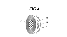
- FIG. 3 is a perspective view showing a state in which a restraining member 22 is wound around a cable bundle 21.
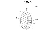
- FIG. It is a perspective view which shows the packaging form 20B of the cable which concerns on the 2nd Embodiment of this invention.
- It is a schematic cross section which shows the packing form 20C of the cable which concerns on the 3rd Embodiment of this invention.
- It is a schematic cross section which shows the packing form 20D of the cable which concerns on the 4th Embodiment of this invention.
- It is the schematic which shows the method of measuring a static friction coefficient and a dynamic friction coefficient.
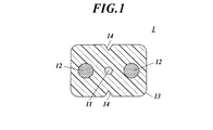
- FIG. 1 is a cross-sectional view perpendicular to the length direction of an indoor cable 1 according to an embodiment of the present invention.
- the indoor cable 1 is generally composed of an optical fiber core wire 11, two tension members 12, and a sheath 13 that collectively covers them.
- the tension members 12 are respectively arranged in the longitudinal direction of the cross section of the indoor cable 1 so as to be separated from the optical fiber core wire 11.
- the tension member 12 bears tension acting on the main body 2.
- a steel wire such as a galvanized steel wire, fiber reinforced plastic (FRP), or the like can be used.
- the sheath 13 covers the optical fiber core wire 11 and the tension member 12, and for example, a thermoplastic resin such as non-halogen flame retardant polyolefin can be used.
- a notch 14 is formed at the center of the sheath 13, and the optical fiber core wire 11 can be easily taken out by breaking the sheath 13 from the notch 14.
- the present invention can be optimally applied to a cable in which the static friction coefficient between indoor cables is 0.50 or less and the dynamic friction coefficient is 0.40 or less.
- the static friction coefficient is larger than 0.50 and the dynamic friction coefficient is larger than 0.40
- the indoor cable 1 is inserted into the existing pipe line when the cable is inserted into the existing pipe line by pushing the cable into the pipe line. This is because it becomes difficult.
- the static friction coefficient is smaller than 0.15 and the dynamic friction coefficient is smaller than 0.10, the roll is easily broken and not only handling becomes difficult, but also the productivity is deteriorated.
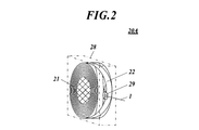
- FIG. 2 is a perspective view showing a cable packing form 20A according to the first embodiment of the present invention.
- the cable packing form 20 ⁇ / b> A includes a cable bundle 21, a restraining member 22, a box-shaped container 28, a guide member 29, and the like.
- FIG. 3 is a perspective view of the cable bundle 21.
- the cable bundle 21 is one in which the indoor cable 1 is wound around a barrel-shaped mandrel (not shown) in a figure 8 shape and then removed from the mandrel.
- a hole is formed in the cable bundle 21 by controlling the rotation speed of the mandrel and the winding pitch, and a guide member 29 is attached to the hole after the cable is removed from the mandrel.
- FIG. 4 is a perspective view showing a state where the restraining member 22 is wound around the cable bundle 21.
- the cable bundle 21 around which the restraining member 22 shown in FIG. 4 is wound is obtained by winding the restraining member 22 around the outer periphery of the cable bundle 21 in a state of being wound around the mandrel and then removing it from the mandrel.
- a wrapping film such as polyethylene can be used as the restraining member 22.
- the restraining member 22 is wound around a hole for attaching the guide member 29.
- the wrapping film When a wrapping film is used as the restraining member 22, the wrapping film preferably has an elongation percentage of 10% to 200%. This is because if the elongation is less than 10%, the binding force is weak. Moreover, it is because it is hard to wind when elongation rate is larger than 200%.
- the cable bundle 21 is particularly easy to collapse when the inner cable 1 is made to have a low friction and a small diameter. However, by winding the restraining member 22 around the outer peripheral portion of the cable bundle 21, the cylindrical shape of the cable bundle 21 is unlikely to collapse and can be easily detached from the mandrel.
- the box-shaped storage container 28 has a rectangular parallelepiped shape, and stores the cable bundle 21 around which the restraining member 22 is wound.
- a cardboard box can be used as the box-shaped container 28.
- the box-shaped container 28 is provided with a hole through which the guide member 29 is inserted.
- the inner end of the indoor cable 1 is inserted through the guide member 29 and pulled out of the box-shaped container 28.
- the indoor cable 1 is drawn out so as to collapse in order from the inner portion of the cable bundle 21.
- FIG. 5 is a perspective view showing a cable packing form 20B according to the second embodiment of the present invention.
- the cable bundle 21, the restraining member 22, the box-shaped storage container 28, and the guide member 29 are the same as those in the first embodiment, and thus description thereof is omitted.
- the closing member 23 may be wound around the entire cable bundle 21 so as to block the openings at both ends of the cable bundle 21 removed from the mandrel. Further, in FIG. 5, the openings at both ends are completely closed, but the closing member 23 may be wound so that a part of the openings remains.
- a wrapping film such as polyethylene can be used.
- the closing member 23 is wound around the guide member 29.
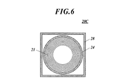
- FIG. 6 is a schematic cross-sectional view showing a cable packing form 20C according to the third embodiment of the present invention.
- the cable bundle 21, the box-shaped container 28, and the guide member 29 are the same as those in the first embodiment, description thereof is omitted.
- a cylindrical member is used as the restraining member 24 wound around the outer peripheral portion of the cable bundle 21.
- a cardboard member can be used as the restraining member 24.
- the cylindrical shape of the cable bundle 21 is not easily collapsed and can be easily detached from the mandrel. Moreover, even one person can be easily accommodated in the box-shaped container 28.
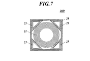
- FIG. 7 is a schematic cross-sectional view showing a cable packing form 20D according to the fourth embodiment of the present invention. Since the cable bundle 21, the box-shaped container 28, and the guide member 29 are the same as those in the first embodiment, description thereof is omitted.
- a cylindrical cable bundle 21 is accommodated inside a rectangular parallelepiped box-shaped container 28, and restraining members 25 that close gaps between the cable bundle 21 are arranged at four corners of the box-shaped container 28. Yes.
- the restraining member 25 has a triangular prism shape, and is made of cardboard, for example.
- the cylindrical shape of the cable bundle 21 becomes difficult to collapse and can be easily detached from the mandrel.
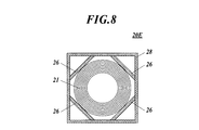
- FIG. 8 is a schematic cross-sectional view showing a cable packing form 20E according to the fifth embodiment of the present invention. Since the cable bundle 21, the box-shaped container 28, and the guide member 29 are the same as those in the first embodiment, description thereof is omitted. As shown in FIG. 8, the cable-like bundle 21 may be restrained by fixing plate-like restraining members 26 to the four corners of the box-shaped container 28. For example, a corrugated cardboard plate can be used as the restraining member 26.
- the present invention will be described in more detail with reference to examples.
- the following payout test was conducted using a wrap film wound around the outer periphery of a cable bundle in which a 1000 m indoor cable was wound in an 8-shape, and housed in a cardboard box-shaped container.
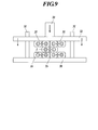
- FIG. 9 is a schematic diagram showing a method for measuring the friction coefficient between cables. Specifically, two 150 mm long indoor cables 35 shown in FIG. 1 are arranged adjacent to each other in parallel on the base 30, and a 300 mm long indoor cable 1 as a sample for measuring a friction coefficient is stacked on the base 30. did. On the sample (measurement sample) optical fiber cable 1, the above-described 150 mm long optical fiber cables 35 and 35 were further stacked as shown in FIG. Thereafter, a holding plate 32 that slides up and down while being guided by a plurality of slide guides 31 erected vertically on the base 30 was placed in parallel with the base 30. The same indoor cables 35 and 1 were used.
- a weight 33 was placed on the holding plate 32, and a constant load of 19.6N was applied in the direction of the arrow.
- the indoor cable 1 for the sample was pulled out at a speed of 100 mm / min in the forward direction.
- a polyethylene wrapping film having a width of 100 mm and a thickness of 0.03 mm was used as the restraining member.
- the wrap winding strength (the tension applied to the wrap when wrapping) was 100 to 200 g, and the number of windings was one. At this time, the elongation percentage of the wrapping film was about 10%.
- the indoor cable was fed out from the guide member 1000 m ⁇ 10 times with respect to the above-mentioned cable packaging form, and the number of occurrences of bending wrinkles was measured.
- the lapping strength was 100 to 200 g and the number of turns was two. Other than that was the same as Example 1.
- the lapping strength was 100 to 200 g and the number of windings was 3 times. Other than that was the same as Example 1.
- the wrap winding strength was 1400-1600 g and the number of windings was one. Other than that was the same as Example 1. At this time, the elongation percentage of the wrapping film was about 100%.
- the wrap winding strength was 1400 to 1600 g and the number of windings was two. Other than that was the same as Example 1.
- the wrap winding strength was 1400 to 1600 g and the number of windings was 3 times. Other than that was the same as Example 1.
- the wrap winding strength was 2800-3200 g and the number of windings was one. Other than that was the same as Example 1. At this time, the elongation percentage of the wrapping film was about 200%.
- the wrap winding strength was 2800-3200 g and the number of windings was 2 times. Other than that was the same as Example 1.
- the wrap winding strength was 2800-3200 g and the number of windings was 3 times. Other than that was the same as Example 1.
- Example 1 No restraining member was used. Other than that was the same as Example 1.
- the wrap winding strength was 100 to 200 g, and the number of windings was one. Other than that was the same as Example 1. At this time, the elongation percentage of the wrapping film was about 10%.
- the lapping strength was 100 to 200 g and the number of turns was two. Otherwise, it was the same as Example 10.
- the lapping strength was 100 to 200 g and the number of windings was 3 times. Otherwise, it was the same as Example 10.
- the wrap winding strength was 1400-1600 g and the number of windings was one. Otherwise, it was the same as Example 10. At this time, the elongation percentage of the wrapping film was about 100%.
- the wrap winding strength was 1400 to 1600 g and the number of windings was two. Otherwise, it was the same as Example 10.
- the wrap winding strength was 1400 to 1600 g and the number of windings was 3 times. Otherwise, it was the same as Example 10.
- the wrap winding strength was 2800-3200 g and the number of windings was one. Otherwise, it was the same as Example 10. At this time, the elongation percentage of the wrapping film was about 200%.
- the wrap winding strength was 2800-3200 g and the number of windings was 2 times. Otherwise, it was the same as Example 10.
- the wrap winding strength was 2800-3200 g and the number of windings was 3 times. Otherwise, it was the same as Example 10.
- Example 2 No restraining member was used. Otherwise, it was the same as Example 10.
- the closing member was wound so as to close 60% of the opening area at both ends.
- a polyethylene wrapping film having a width of 100 mm and a thickness of 0.03 mm was used, and the wrapping strength was 100 to 200 g. Other than that was the same as Example 1. At this time, the elongation percentage of the wrapping film used as the closing member was about 10%.
- the cylindrical restraint member shown in FIG. 6 made of cardboard was used as the restraint member. Other than that was the same as Example 1.
- a triangular prism shaped restraining member shown in FIG. 7 made of cardboard was used as the restraining member. Other than that was the same as Example 1.
- a triangular prism shaped restraining member shown in FIG. 7 made of cardboard was used as the restraining member. Otherwise, the procedure was the same as in Example 21.
- Example 1 three bending wrinkles occurred. In Examples 4, 7, and 10, one bending wrinkle occurred. In Examples 2, 3, 5, 6, 8, 9, and 11 to 18, no bending wrinkles occurred. On the other hand, bending wrinkles occurred 25 times in Comparative Example 1 and 11 times in Comparative Example 2. In addition, bending wrinkles were less likely to occur when the constraining member was wound only once than when it was wound twice or three times. This is because the restraining force of the cable bundle is increased by winding the restraining member a plurality of times.
- Example 19 in which the closing member was provided in addition to the restraining member, bending wrinkles did not occur. In addition, no bending wrinkles occurred in Examples 20 to 23 in which the restraint member using the tubular restraint member shown in FIG. 6 made of cardboard or the triangular prism-like restraint member shown in FIG. 7 was used.
Landscapes
- Engineering & Computer Science (AREA)
- Mechanical Engineering (AREA)
- Packaging Of Annular Or Rod-Shaped Articles, Wearing Apparel, Cassettes, Or The Like (AREA)
- Packages (AREA)
- Storage Of Web-Like Or Filamentary Materials (AREA)
Abstract
Description
〔第1実施形態〕
図1は本発明の実施形態に係るインドアケーブル1の長さ方向と垂直な断面図である。図1に示すように、インドアケーブル1は、光ファイバ心線11と、2本のテンションメンバ12と、これらを一括被覆するシース13とから概略構成される。
ケーブル束21の外周部に拘束部材22を巻きつけることで、ケーブル束21の円筒形状が崩れにくくなっているため、一人でも容易に箱状収容容器28に収容することができる。
図5は本発明の第2の実施形態に係るケーブルの梱包形態20Bを示す斜視図である。なお、ケーブル束21、拘束部材22、箱状収容容器28やガイド部材29は第1実施形態と同様であるので説明を割愛する。図5に示すように、マンドレルから取り外したケーブル束21に対し、さらに両端の開口を塞ぐように閉塞部材23をケーブル束21全体に巻きつけてもよい。また、図5では両端の開口を完全に塞いでいるが、一部開口が残るように閉塞部材23を巻きつけてもよい。
閉塞部材23としては、例えばポリエチレン等のラッピングフィルムを用いることができる。閉塞部材23はガイド部材29を避けて巻きつけられる。
図6は本発明の第3の実施形態に係るケーブルの梱包形態20Cを示す模式断面図である。なお、ケーブル束21、箱状収容容器28やガイド部材29は第1実施形態と同様であるので説明を割愛する。本実施形態においては、ケーブル束21の外周部に巻きつけられる拘束部材24として、筒状の部材が用いられている。拘束部材24には、例えばダンボール製の部材を用いることができる。
図7は本発明の第4の実施形態に係るケーブルの梱包形態20Dを示す模式断面図である。ケーブル束21、箱状収容容器28やガイド部材29は第1実施形態と同様であるので説明を割愛する。本実施形態においては、直方体形状の箱状収容容器28の内部に円筒形のケーブル束21が収容され、箱状収容容器28の四隅にケーブル束21との隙間を塞ぐ拘束部材25が配置されている。拘束部材25は三角柱形状であり、例えばダンボールから形成される。
図8は本発明の第5の実施形態に係るケーブルの梱包形態20Eを示す模式断面図である。ケーブル束21、箱状収容容器28やガイド部材29は第1実施形態と同様であるので説明を割愛する。図8に示すように、箱状収容容器28の四隅に板状の拘束部材26を固定し、ケーブル束21を拘束してもよい。拘束部材26には、例えばダンボール板を用いることができる。
以下、本発明について、実施例を挙げてさらに詳細に説明する。
光ファイバ心線の直径は、0.25mmとした。
テンションメンバには、直径0.4mmの亜鉛メッキ鋼線を2本用いた。
シースには、ノンハロゲン難燃ポリオレフィンを用いた。
ケーブル同士の動摩擦係数は0.25、静止摩擦係数は0.20であった。
また、ケーブルの曲げ剛性(IEC60794-1-2 E17C準拠 D=40mmにて実施)が92gfのものを用いた。
具体的には、ベース30上に図1に示す150mm長のインドアケーブル35を2本隣接して並行に並べ、この上に摩擦係数を測定する試料である300mm長のインドアケーブル1を、俵積みした。この試料用(測定サンプル)光ファイバケーブル1上に、前述した150mm長の光ファイバケーブル35、35を図9のようにさらに俵積みした。
その後、ベース30上に垂直に立設させた複数本のスライドガイド31によってガイドしながら上下にスライドする抑え板32をベース30と平行に載せた。インドアケーブル35、1は同じものを使用した。
尚、試験環境は、温度23±2℃、湿度50±10%とした。
ところでインドアケーブル15、20は、試験が1回(n=1)完了する毎に交換した。
拘束部材には、幅100mm、厚さ0.03mmのポリエチレン製ラッピングフィルムを用いた。
ラップ巻き強度(ラップ巻きをする際、ラップにかける張力)を100~200g、巻き数を1回とした。このときラッピングフィルムの伸び率は約10%であった。
拘束部材を用いなかった。それ以外は、実施例1と同様とした。
ラップ巻き強度を100~200g、巻き数を1回とした。それ以外は、実施例1と同様とした。このときラッピングフィルムの伸び率は約10%であった。
拘束部材を用いなかった。それ以外は、実施例10と同様とした。
結果を表1、表2、表3に示す。

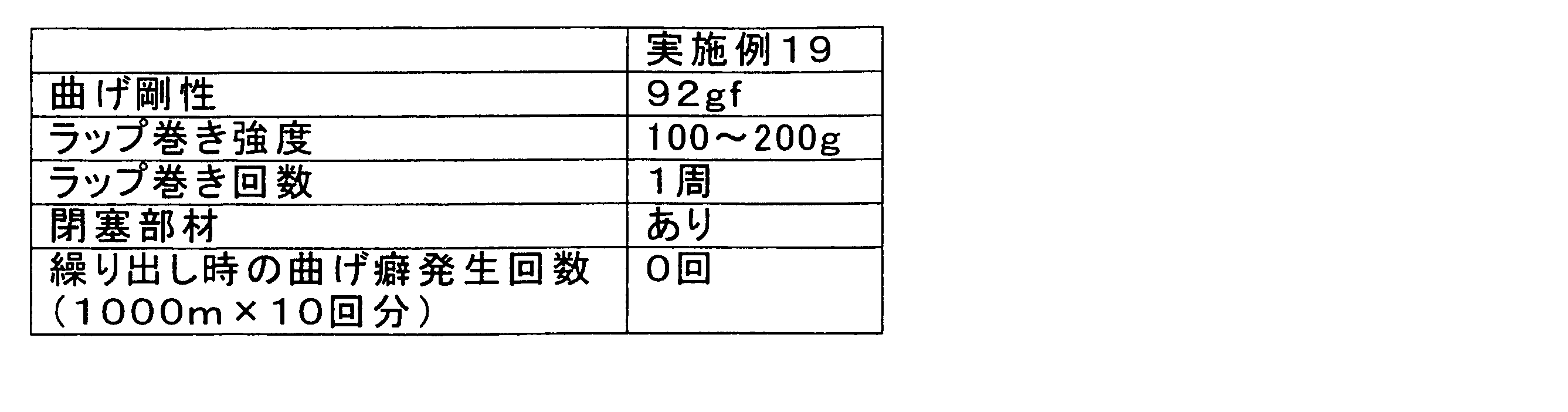
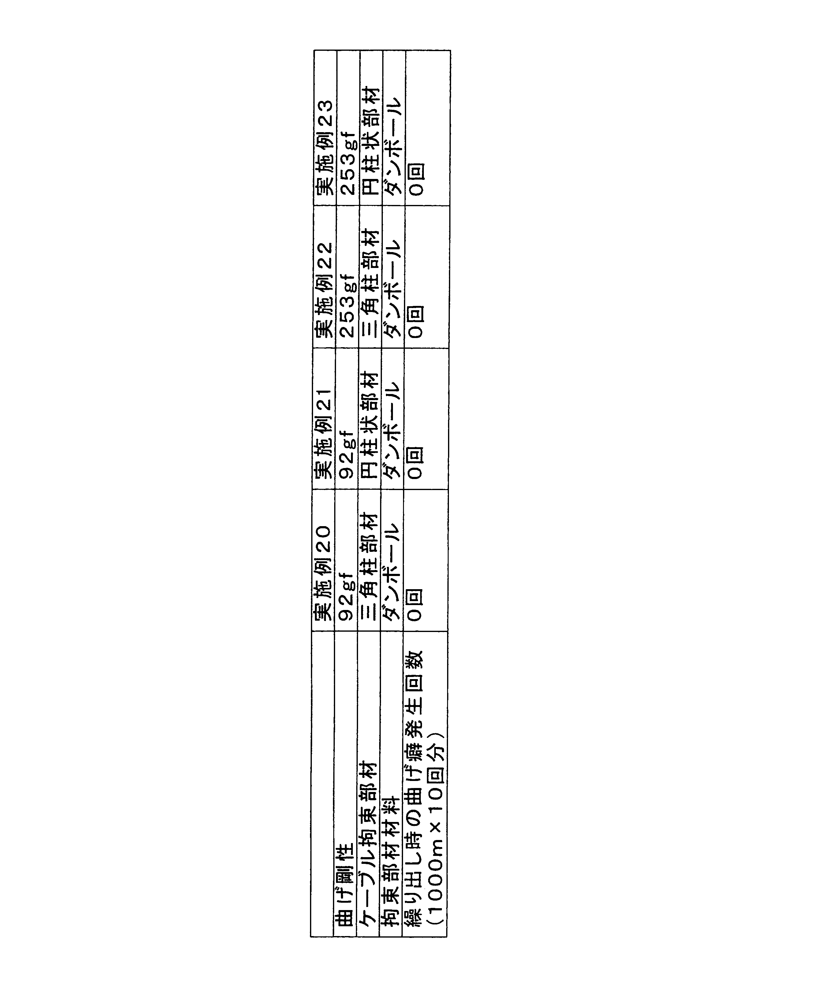
一方、比較例1では25回、比較例2では11回の曲げ癖が発生した。
また、拘束部材を1周だけ巻いたものよりも、2周、3周巻いたもののほうが曲げ癖が発生しにくかった。これは、拘束部材を複数回巻くことで、ケーブル束の拘束力が強くなるためである。
また、拘束部材に、ダンボールからなる図6に示す筒状の拘束部材や、図7に示す三角柱形状の拘束部材を用いた実施例20~23においても曲げ癖が発生しなかった。
20A,20B,20C,20D,20E ケーブルの梱包形態
21 ケーブル束
22,24,25,26 拘束部材
23 閉塞部材
28 箱状収容容器
29 ガイド部材
Claims (6)
- ケーブルを8の字状に巻きつけてなる円筒形のケーブル束と、
前記ケーブル束の外周部に配置され、前記ケーブル束を拘束する拘束部材と、
前記ケーブル束及び前記拘束部材を収容する収容容器と、
を備えることを特徴とするケーブルの梱包形態。 - 前記拘束部材は、ラッピングフィルムであることを特徴とする請求項1に記載のケーブルの梱包形態。
- 前記拘束部材が伸び率10%~200%の範囲内でケーブルを拘束していることを特徴とする請求項2に記載のケーブルの梱包形態。
- 前記ケーブル束には、半径方向に貫通するガイド部材が設けられ、
前記拘束部材は前記ガイド部材を避けて設けられていることを特徴とする請求項1~3のいずれか一項に記載のケーブルの梱包形態。 - 前記ケーブル束の両端の開口を閉塞する閉塞部材が設けられていることを特徴とする請求項1~4のいずれか一項に記載のケーブルの梱包形態。
- 前記閉塞部材は、ラッピングフィルムであることを特徴とする請求項5に記載のケーブルの梱包形態。
Priority Applications (5)
| Application Number | Priority Date | Filing Date | Title |
|---|---|---|---|
| EP09805020.6A EP2308775B1 (en) | 2008-08-08 | 2009-08-06 | Packing configuration of cable |
| ES09805020.6T ES2438097T3 (es) | 2008-08-08 | 2009-08-06 | Configuraciones de empaquetado de cable |
| BRPI0917117-7A BRPI0917117B1 (pt) | 2008-08-08 | 2009-08-06 | Configuração de acondicionamento de cabo. |
| US13/055,615 US20110132786A1 (en) | 2008-08-08 | 2009-08-06 | Packing configuration of cable |
| US14/263,465 US9604742B2 (en) | 2008-08-08 | 2014-04-28 | Method for packing cable |
Applications Claiming Priority (2)
| Application Number | Priority Date | Filing Date | Title |
|---|---|---|---|
| JP2008205424A JP5390806B2 (ja) | 2008-08-08 | 2008-08-08 | ケーブルの梱包形態 |
| JP2008-205424 | 2008-08-08 |
Related Child Applications (2)
| Application Number | Title | Priority Date | Filing Date |
|---|---|---|---|
| US13/055,615 A-371-Of-International US20110132786A1 (en) | 2008-08-08 | 2009-08-06 | Packing configuration of cable |
| US14/263,465 Division US9604742B2 (en) | 2008-08-08 | 2014-04-28 | Method for packing cable |
Publications (1)
| Publication Number | Publication Date |
|---|---|
| WO2010016537A1 true WO2010016537A1 (ja) | 2010-02-11 |
Family
ID=41663754
Family Applications (1)
| Application Number | Title | Priority Date | Filing Date |
|---|---|---|---|
| PCT/JP2009/063921 Ceased WO2010016537A1 (ja) | 2008-08-08 | 2009-08-06 | ケーブルの梱包形態 |
Country Status (6)
| Country | Link |
|---|---|
| US (2) | US20110132786A1 (ja) |
| EP (1) | EP2308775B1 (ja) |
| JP (1) | JP5390806B2 (ja) |
| BR (1) | BRPI0917117B1 (ja) |
| ES (1) | ES2438097T3 (ja) |
| WO (1) | WO2010016537A1 (ja) |
Families Citing this family (8)
| Publication number | Priority date | Publication date | Assignee | Title |
|---|---|---|---|---|
| DE202013011668U1 (de) | 2013-11-12 | 2014-04-14 | Michael Zupritt | Vorrichtung zum Halten eines seilförmigen Körpers |
| US10538379B2 (en) * | 2014-03-11 | 2020-01-21 | Lincoln Global, Inc. | Welding wire coil package |
| USD761637S1 (en) | 2014-05-07 | 2016-07-19 | Lincoln Global, Inc. | Wire coil package |
| US9950895B2 (en) | 2014-07-03 | 2018-04-24 | Lincoln Global, Inc. | Welding wire coil packaging system |
| JPWO2018220984A1 (ja) * | 2017-06-01 | 2020-05-21 | 住友電気工業株式会社 | 光ファイバの保管方法、輸送方法および光ファイバ巻回ボビン |
| USD991299S1 (en) | 2021-04-30 | 2023-07-04 | Esab Ab | Hood for a welding consumable container |
| USD998664S1 (en) | 2021-04-30 | 2023-09-12 | Esab Ab | Welding consumable container |
| USD998665S1 (en) | 2021-04-30 | 2023-09-12 | Esab Ab | Welding consumable container |
Citations (6)
| Publication number | Priority date | Publication date | Assignee | Title |
|---|---|---|---|---|
| JPS6311373U (ja) * | 1986-07-04 | 1988-01-25 | ||
| JP2001063784A (ja) | 1999-08-30 | 2001-03-13 | Tsushin Kogyo Kk | ケーブル用収納容器 |
| JP2004359300A (ja) * | 2003-06-05 | 2004-12-24 | Yazaki Corp | 束巻き電線 |
| JP2006248613A (ja) * | 2005-03-07 | 2006-09-21 | Lincoln Global Inc | 溶接ワイヤー容器及びその製造方法 |
| JP2007269382A (ja) * | 2006-03-31 | 2007-10-18 | Kobelco & Materials Copper Tube Inc | 金属コイル用スペーサ |
| JP2007326719A (ja) * | 2002-03-26 | 2007-12-20 | Mirai Ind Co Ltd | 通水管の梱包装置 |
Family Cites Families (51)
| Publication number | Priority date | Publication date | Assignee | Title |
|---|---|---|---|---|
| US1640368A (en) * | 1926-12-13 | 1927-08-30 | Us Asbestos Company | Asbestos rope or wick package |
| US1684540A (en) * | 1927-03-23 | 1928-09-18 | William E Hooper & Sons Compan | Package |
| GB311122A (en) * | 1928-05-30 | 1929-05-09 | Robert Nicoll Robertson | Improvements in or relating to spools of twine, thread or the like |
| US2634922A (en) * | 1949-07-28 | 1953-04-14 | Jr Walter P Taylor | Package |
| US2767938A (en) * | 1953-03-26 | 1956-10-23 | Jr Walter P Taylor | Winding flexible material |
| US2716008A (en) * | 1953-03-26 | 1955-08-23 | Jr Walter P Taylor | Package of flexible material |
| US2921676A (en) * | 1957-12-23 | 1960-01-19 | Superior Machinery Corp | Yarn package |
| BE621846A (ja) * | 1961-08-31 | 1900-01-01 | ||
| US3114456A (en) * | 1962-07-10 | 1963-12-17 | Lewis H Van Billiard | Payout coils |
| DE1586512B1 (de) * | 1967-11-02 | 1970-08-06 | Buettner Kg Maschinenfabrik | Umschnuerungsmittel-Trommel |
| US3700185A (en) * | 1970-02-17 | 1972-10-24 | Anaconda Wire & Cable Co | Dispensable coil package |
| US3677491A (en) * | 1970-10-09 | 1972-07-18 | Windings Inc | Box with inwardly tapering guide cones for universal wind package with radial pay-out |
| US3915301A (en) * | 1971-02-08 | 1975-10-28 | Owens Corning Fiberglass Corp | Covered tubular package of glass roving and method of making |
| US3803796A (en) * | 1972-02-16 | 1974-04-16 | Windings Inc | Method of forming and packaging flexible material with an inner end payout |
| GB1398938A (en) * | 1973-07-05 | 1975-06-25 | Windings Inc | Method of producing a package of flexible material with radial inner end feedout |
| US4019636A (en) * | 1975-11-03 | 1977-04-26 | Belden Corporation | Strand package and carton therefor |
| US3982712A (en) * | 1975-11-28 | 1976-09-28 | Bassett Eugene E | Coil dispenser |
| US4067441A (en) * | 1976-05-14 | 1978-01-10 | Windings, Inc. | Coil of flexible material with inserts in outer wall |
| US4160533A (en) * | 1978-01-24 | 1979-07-10 | Windings, Inc. | Container with octagonal insert and corner payout |
| US4274607A (en) * | 1979-12-03 | 1981-06-23 | Belden Corporation | Guide device for use in elongate filament dispensing package and the like |
| GB2085404A (en) * | 1980-10-15 | 1982-04-28 | Windings Inc | Packaged coils |
| US4467916A (en) * | 1982-04-26 | 1984-08-28 | Ppg Industries, Inc. | Tubular glass fiber package and method |
| US4724960A (en) * | 1982-10-07 | 1988-02-16 | Ethyl Corporation | Greenhouse film package |
| US4493464A (en) * | 1983-09-19 | 1985-01-15 | Owens-Corning Fiberglas Corporation | Packaged strand |
| US4687294A (en) * | 1984-05-25 | 1987-08-18 | Cooper Industries, Inc. | Fiber optic plenum cable |
| JP2563788B2 (ja) | 1986-03-07 | 1996-12-18 | セイコーエプソン株式会社 | プリンタのキヤリツジ制御方法 |
| US4817796A (en) * | 1988-03-04 | 1989-04-04 | Essex Group, Inc. | Packing box |
| US5129514A (en) * | 1991-08-12 | 1992-07-14 | The Ensign-Bickford Company | Flexible cord winding and packaging configuration and method for making such package |
| US5238114A (en) * | 1992-04-10 | 1993-08-24 | Owens-Corning Fiberglas Technology, Inc. | Strand packages |
| IT231566Y1 (it) * | 1993-02-23 | 1999-08-04 | Sidergas Srl | Contenitore di imballaggio e di svolgimento di una matassa di filo metallico |
| US5561731A (en) * | 1995-06-15 | 1996-10-01 | Siecor Corporation | Flexible casing for optical ribbons |
| US5628167A (en) * | 1995-07-13 | 1997-05-13 | Illinois Tool Works Inc. | Method and apparatus for wrapping elongate load having generally circular or generally annular ends |
| GB9626234D0 (en) * | 1996-12-18 | 1997-02-05 | Mobil Plastics Europ Inc | Wrapping apparatus |
| US5979812A (en) * | 1998-04-21 | 1999-11-09 | Windings, Inc. | Coil with large payout hole and tube for kinkless payout |
| US5918745A (en) * | 1998-04-28 | 1999-07-06 | Aluminum Company Of America | Stretch wrapped heavy coils |
| JP2000025713A (ja) * | 1998-07-02 | 2000-01-25 | Fuji Seal Inc | 環状物品の包装装置 |
| BR0011119A (pt) * | 1999-06-01 | 2002-02-26 | Pesmel Oy | Embalagem de rolo, e, processo de produção de uma embalagem de rolo |
| JP3970499B2 (ja) | 1999-06-01 | 2007-09-05 | 昭和電線ケーブルシステム株式会社 | 中間牽引用および先端牽引用低摩擦外被ケーブル |
| US6264031B1 (en) * | 1999-07-06 | 2001-07-24 | Automatic Handling, Inc. | Package for a roll |
| ATE267740T1 (de) * | 1999-08-05 | 2004-06-15 | Sica Spa | Verfahren und maschine zum verpacken von ringförmigen strängen eines flexiblen länglichen elements |
| US6594427B1 (en) * | 2000-08-23 | 2003-07-15 | Fitel Usa Corp. | Communication cable having polypropylene copolymer jacketing material |
| FR2817839A1 (fr) * | 2000-12-08 | 2002-06-14 | M R Ind | Conditionnement pour produit en rouleau |
| JP2003014998A (ja) * | 2001-06-29 | 2003-01-15 | Fujikura Ltd | 光ファイバ心線 |
| US6564943B2 (en) * | 2001-07-13 | 2003-05-20 | Lincoln Global, Inc. | Container for welding wire |
| US6853782B2 (en) * | 2001-07-16 | 2005-02-08 | Fujikura Ltd. | Optical fiber drop cable |
| US7421169B2 (en) * | 2003-06-20 | 2008-09-02 | Fujikura Ltd. | Optical fiber cable |
| DE10329193A1 (de) * | 2003-06-28 | 2005-01-20 | H. Böhl GmbH | Verfahren sowie Wickelmaschine zum Umwickeln eines Gegenstandes |
| JP2005107441A (ja) | 2003-10-02 | 2005-04-21 | Sumitomo Electric Ind Ltd | 光ファイバケーブル |
| WO2006051898A1 (ja) * | 2004-11-11 | 2006-05-18 | Sumitomo Electric Industries, Ltd. | 光ケーブル |
| EP2075605A4 (en) * | 2007-02-08 | 2011-11-09 | Sumitomo Electric Industries | OPTICAL CABLE |
| US8056717B2 (en) * | 2008-07-07 | 2011-11-15 | Lincoln Global, Inc. | Overwrap for packaged articles |
-
2008
- 2008-08-08 JP JP2008205424A patent/JP5390806B2/ja active Active
-
2009
- 2009-08-06 BR BRPI0917117-7A patent/BRPI0917117B1/pt not_active IP Right Cessation
- 2009-08-06 WO PCT/JP2009/063921 patent/WO2010016537A1/ja not_active Ceased
- 2009-08-06 US US13/055,615 patent/US20110132786A1/en not_active Abandoned
- 2009-08-06 EP EP09805020.6A patent/EP2308775B1/en not_active Not-in-force
- 2009-08-06 ES ES09805020.6T patent/ES2438097T3/es active Active
-
2014
- 2014-04-28 US US14/263,465 patent/US9604742B2/en not_active Expired - Fee Related
Patent Citations (6)
| Publication number | Priority date | Publication date | Assignee | Title |
|---|---|---|---|---|
| JPS6311373U (ja) * | 1986-07-04 | 1988-01-25 | ||
| JP2001063784A (ja) | 1999-08-30 | 2001-03-13 | Tsushin Kogyo Kk | ケーブル用収納容器 |
| JP2007326719A (ja) * | 2002-03-26 | 2007-12-20 | Mirai Ind Co Ltd | 通水管の梱包装置 |
| JP2004359300A (ja) * | 2003-06-05 | 2004-12-24 | Yazaki Corp | 束巻き電線 |
| JP2006248613A (ja) * | 2005-03-07 | 2006-09-21 | Lincoln Global Inc | 溶接ワイヤー容器及びその製造方法 |
| JP2007269382A (ja) * | 2006-03-31 | 2007-10-18 | Kobelco & Materials Copper Tube Inc | 金属コイル用スペーサ |
Non-Patent Citations (1)
| Title |
|---|
| See also references of EP2308775A4 |
Also Published As
| Publication number | Publication date |
|---|---|
| US20140230375A1 (en) | 2014-08-21 |
| BRPI0917117A2 (pt) | 2015-11-03 |
| JP2010036978A (ja) | 2010-02-18 |
| EP2308775A1 (en) | 2011-04-13 |
| US20110132786A1 (en) | 2011-06-09 |
| US9604742B2 (en) | 2017-03-28 |
| BRPI0917117B1 (pt) | 2019-04-09 |
| EP2308775A4 (en) | 2011-10-12 |
| EP2308775B1 (en) | 2013-10-16 |
| ES2438097T3 (es) | 2014-01-15 |
| JP5390806B2 (ja) | 2014-01-15 |
Similar Documents
| Publication | Publication Date | Title |
|---|---|---|
| JP5390806B2 (ja) | ケーブルの梱包形態 | |
| CN1202430C (zh) | 一种包含光导纤维卷筒及光导纤维卷筒外壳的组合件 | |
| US8301003B2 (en) | Cable network interconnection system with connector package and cable package | |
| JP5719052B1 (ja) | 光ケーブル | |
| US8750662B1 (en) | Fiber optic cable for very-short-distance networks | |
| US7330627B2 (en) | Coiled cable products and methods of forming the same | |
| US9290358B2 (en) | Retractable in-wall cable system | |
| JP4609864B2 (ja) | ケーブルの梱包体 | |
| JP3970499B2 (ja) | 中間牽引用および先端牽引用低摩擦外被ケーブル | |
| AU2021335442A1 (en) | Optical fiber cable | |
| EP3134342B1 (en) | Shipping container for delivering cables | |
| JP6459833B2 (ja) | 光ファイバケーブル | |
| WO2022076396A1 (en) | Dispenser for a continuous strip of a substrate supporting bend-sensitive items | |
| JP2912615B1 (ja) | 電線・ケーブル包装体 | |
| US10947078B2 (en) | Winding system for elongated elements | |
| AU2010100772A4 (en) | Structure for axis-free fiber cable winding | |
| JP5829439B2 (ja) | 古紙収容結束器 | |
| JP2012088359A (ja) | 光ケーブル | |
| KR20100036040A (ko) | 케이블 권취구조체, 이 권취구조체를 수납하는 포장 박스 및 이 포장박스로부터 케이블을 인출하는 방법 | |
| JP2023155697A (ja) | 光ケーブル | |
| JPH04355411A (ja) | 通信線収納具 | |
| EP3838821A1 (en) | Coiled product dispensing kit | |
| JPH10264938A (ja) | 束取りされた線条体の包装方法、および引き出し方法 | |
| WO2025134902A1 (ja) | 光ファイバケーブル | |
| JP2012096827A (ja) | ケーブル梱包体 |
Legal Events
| Date | Code | Title | Description |
|---|---|---|---|
| 121 | Ep: the epo has been informed by wipo that ep was designated in this application |
Ref document number: 09805020 Country of ref document: EP Kind code of ref document: A1 |
|
| WWE | Wipo information: entry into national phase |
Ref document number: 2009805020 Country of ref document: EP |
|
| WWE | Wipo information: entry into national phase |
Ref document number: 13055615 Country of ref document: US |
|
| NENP | Non-entry into the national phase |
Ref country code: DE |
|
| ENP | Entry into the national phase |
Ref document number: PI0917117 Country of ref document: BR Kind code of ref document: A2 Effective date: 20110207 |