WO2010020125A1 - 基于数字用户线的功率优化方法、系统及设备 - Google Patents
基于数字用户线的功率优化方法、系统及设备 Download PDFInfo
- Publication number
- WO2010020125A1 WO2010020125A1 PCT/CN2009/071378 CN2009071378W WO2010020125A1 WO 2010020125 A1 WO2010020125 A1 WO 2010020125A1 CN 2009071378 W CN2009071378 W CN 2009071378W WO 2010020125 A1 WO2010020125 A1 WO 2010020125A1
- Authority
- WO
- WIPO (PCT)
- Prior art keywords
- parameter
- line
- rate
- power
- target
- Prior art date
- Legal status (The legal status is an assumption and is not a legal conclusion. Google has not performed a legal analysis and makes no representation as to the accuracy of the status listed.)
- Ceased
Links
Classifications
-
- H—ELECTRICITY
- H04—ELECTRIC COMMUNICATION TECHNIQUE
- H04B—TRANSMISSION
- H04B3/00—Line transmission systems
- H04B3/02—Details
- H04B3/32—Reducing cross-talk, e.g. by compensating
-
- H—ELECTRICITY
- H04—ELECTRIC COMMUNICATION TECHNIQUE
- H04M—TELEPHONIC COMMUNICATION
- H04M11/00—Telephonic communication systems specially adapted for combination with other electrical systems
- H04M11/06—Simultaneous speech and data transmission, e.g. telegraphic transmission over the same conductors
- H04M11/062—Simultaneous speech and data transmission, e.g. telegraphic transmission over the same conductors using different frequency bands for speech and other data
-
- H—ELECTRICITY
- H04—ELECTRIC COMMUNICATION TECHNIQUE
- H04M—TELEPHONIC COMMUNICATION
- H04M3/00—Automatic or semi-automatic exchanges
- H04M3/005—Interface circuits for subscriber lines
- H04M3/007—Access interface units for simultaneous transmission of speech and data, e.g. digital subscriber line [DSL] access interface units
-
- H—ELECTRICITY
- H04—ELECTRIC COMMUNICATION TECHNIQUE
- H04M—TELEPHONIC COMMUNICATION
- H04M3/00—Automatic or semi-automatic exchanges
- H04M3/22—Arrangements for supervision, monitoring or testing
- H04M3/26—Arrangements for supervision, monitoring or testing with means for applying test signals or for measuring
- H04M3/28—Automatic routine testing ; Fault testing; Installation testing; Test methods, test equipment or test arrangements therefor
- H04M3/30—Automatic routine testing ; Fault testing; Installation testing; Test methods, test equipment or test arrangements therefor for subscriber's lines, for the local loop
- H04M3/305—Automatic routine testing ; Fault testing; Installation testing; Test methods, test equipment or test arrangements therefor for subscriber's lines, for the local loop testing of physical copper line parameters, e.g. capacitance or resistance
- H04M3/306—Automatic routine testing ; Fault testing; Installation testing; Test methods, test equipment or test arrangements therefor for subscriber's lines, for the local loop testing of physical copper line parameters, e.g. capacitance or resistance for frequencies above the voice frequency, e.g. xDSL line qualification
Definitions
- the present invention relates to the field of communications technologies, and in particular, to a power optimization method, system, and device based on DSL (Digital Subscriber Line).
- DSL Digital Subscriber Line
- DSL technology is a technology for high-speed data transmission through UTP (Unshielded Twist Pair), including ADSL (Asymmetric Digital Subscriber Line), VDSL (Very-high-bit-rate Digital). Subscriber Line, Very High Speed Digital Subscriber Line), IDSL (Integrated Services Digital Network Digital Subscriber Line) and SHDSL (Single-pair High-bit-rate Digital Subscriber Line) Line) and so on.
- ADSL Asymmetric Digital Subscriber Line
- VDSL Very-high-bit-rate Digital
- Subscriber Line Very High Speed Digital Subscriber Line
- IDSL Integrated Services Digital Network Digital Subscriber Line
- SHDSL Single-pair High-bit-rate Digital Subscriber Line
- DSL Downlink Traffic
- POTS Personal Telephone Service, traditional telephone
- Service Traffic is transmitted on the same pair of UTPs.
- the DSL service is transmitted on a high frequency band, and DMT (Discrete Multi-Tone Modulation) is used to modulate and demodulate the service signal, and the POTS is transmitted in the baseband part, and the signals of the above two services are separated/ The integrator performs unified processing.
- DMT Discrete Multi-Tone Modulation
- the accessed DSL service may have multiple channels, and the DSL Access Multiplexer (DSL Access Multiplexer) can be used for both DSL service signals at both the central office and the user end.
- DSL Access Multiplexer DSL Access Multiplexer
- POTS service signal processing is a schematic diagram of the access system.
- the client DSLAM 120 includes a client transceiver unit 121 and a split/integrator 122. In the uplink direction, the client transceiver unit 121 receives the multi-channel DSL signal from the computer 110 and performs amplification processing to transmit the processed multiple DSL signals to the separation.
- the splitter/integrator 122 integrates the multiple DSL signals from the client transceiver unit 121 and the POTS signals of the telephone terminal 130.
- the integrated signal is transmitted through multiple UTP 140, by the central office
- the split/conformer 151 in the DSLAM 150 receives.
- the splitter/integrator 151 separates the received signals, transmits the POTS signals therein to the public switched telephone network 160, and transmits the multiplexed DSL signals thereto to the central office transceiver unit 152.
- the central office transceiver unit 152 then amplifies the received multiple DSL signals and sends them to the network management system 170.
- the transmission process of the signal in the downlink direction is consistent with the above transmission process in the uplink direction, and details are not described herein again.
- the inventor found that although the maximum line rate can meet the user's requirement for the rate, the line rate is only met with the emergence of services with higher line quality requirements such as VOIP service and IPTV service.
- the requirements may cause the quality of the line to degrade, such as voice delay and frame loss, because the line running quality is unstable, which reduces the user experience; and because in most cases, the user does not need a high rate, and the line rate is the largest.
- the approach will waste power in the system, increase crosstalk between lines, and increase the cost of the system.
- the purpose of the embodiments of the present invention is to provide a power optimization method, system, and device based on DSL, which can reduce the power consumption in the system and reduce the crosstalk between the lines while satisfying the QoE (Quality of Experience).
- a power optimization method based on a digital subscriber line including:
- the physical layer target parameter and the line operation information are used as input parameters of the power optimization algorithm, and the optimized power spectrum is obtained by the power optimization algorithm.
- a power optimization system based on a digital subscriber line comprising: a network management device and a central office device, where the network management device is configured to collect service information of the user, according to the service information corresponding to the service information
- the QoE parameter obtains a physical layer target parameter, receives line operation information of the user reported by the central office device, uses the physical layer target parameter and the line operation information as input parameters of the power optimization algorithm, and obtains optimized power by using a power optimization algorithm.
- a power optimization device based on a digital subscriber line comprising:
- a physical layer parameter obtaining unit configured to collect service information of the user, and obtain a physical layer target parameter according to a QoE parameter corresponding to the service information
- a line operation information receiving unit configured to receive line operation information of the user
- the optimized power spectrum acquisition unit is configured to use the physical layer target parameter and the line operation information as input parameters of the power optimization algorithm, and obtain an optimized power spectrum by using a power optimization algorithm.
- the service information of the user is collected, the physical layer target parameter is obtained according to the QoE parameter corresponding to each service information, and the number of line operation information of the user is received, and the power optimization is performed.
- the algorithm obtains an optimized power spectrum that is different from the normal power spectrum, but a power spectrum that best matches the target parameters of the physical layer.
- the DSL parameter optimization is implemented by using the embodiment of the present invention.
- the DSL network is optimized according to QoE, the user experience is improved, and the minimum power method is used to optimize the transmission power spectrum. Therefore, the QoE is satisfied, and the total power consumption is reduced.
- the crosstalk between different DSL signals is reduced, which makes the signal transmission of the system stable and improves the quality of service transmission.
- FIG. 1 is a schematic structural diagram of a system of an existing xDSL
- FIG. 2 is a flow chart of an embodiment of a DSL-based power optimization method according to the present invention.
- FIG. 3 is a schematic structural diagram of an application of an embodiment of a power optimization method according to the present invention.
- FIG. 4 is a flow chart of another embodiment of a DSL-based power optimization method according to the present invention
- FIG. 5 is a flowchart of another embodiment of a DSL-based power optimization method according to the present invention
- FIG. 6 is a DSL-based power optimization method according to the present invention
- FIG. 7 is a schematic structural diagram of an embodiment of a DSL-based power optimization system according to the present invention
- FIG. 8 is a schematic structural diagram of an embodiment of a DSL-based power optimization apparatus according to the present invention
- FIG. 10 is a schematic structural diagram of another embodiment of a DSL-based power optimization apparatus according to the present invention
- FIG. 11 is another schematic diagram of a DSL-based power optimization apparatus according to another embodiment of the present invention
- Embodiments of the present invention provide a DSL-based power optimization method, system, and device.
- the method may include: collecting service information of a user, and acquiring a physical layer target parameter according to a QoE parameter corresponding to the service information; receiving line operation information of the user; and operating the physical layer target parameter and the line
- the information is obtained by the power optimization algorithm to obtain the optimized power language.
- Good that is, it is difficult to improve performance indicators such as bit error rate and dropped rate, so the customer experience is not high.
- the embodiment of the present invention optimizes the DSL network by using QoE as a guide, and optimizes the transmission power spectrum by the DSM (Dynamic Spectrum Management) algorithm, and encodes the parameters according to different service types. Optimize at the same time to maximize QoE.
- DSM Dynamic Spectrum Management
- Step 201 Collect service information of a user, and obtain a physical layer target parameter according to a QoE parameter corresponding to the service information.
- the service information of the user that is delivered according to the preset time interval may be received; or the request for acquiring the service information of the user is sent, and the user returned according to the request is received.
- Business information When collecting the service information of the user, the service information of the user that is delivered according to the preset time interval may be received; or the request for acquiring the service information of the user is sent, and the user returned according to the request is received.
- the corresponding relationship between the pre-stored service type and the QoE parameter is searched, the QoE parameter corresponding to each service information is obtained, and the same QoE parameter of different services is compared, and the same QoE parameter is obtained.
- the QoE parameter with the largest value converts the QoE parameter with the largest value to the physical layer target parameter according to the correspondence between the QoE parameter and the physical layer target parameter.
- the QoE parameters include: end-to-end network delay, jitter parameter, maximum error duration, number of IP packet loss, error packet loss interval, IP layer net rate, IP packet loss rate, IP bit error rate; Layer target parameters include: Minimum Net Rate, Minimum INP, Maximum Delay, Target Signal to Noise Ratio Margin.
- Step 202 Receive line operation information of the user, where the line operation information includes test parameters and pre-stored line target parameters.
- the line operation information of the receiving user may be used in the following manner: receiving the line running information of the user reported by the central office device according to a preset time interval; or sending the station information to the central office device.
- the request for the line operation information where the request includes the identifier of the user, and receives the line operation information of the user returned by the central office device.
- the test parameters include: background noise and channel attenuation; and the pre-stored line target parameters include: a maximum reachable rate, a maximum power, and a maximum power of each sub-band.
- Step 203 The physical layer target parameter and the line running information are used as input parameters of the power optimization algorithm, and the optimized power spectrum is obtained by the power optimization algorithm.
- Embodiments of the power optimization method based on DSL of the present invention are generally applied to the structural schematic shown in FIG.
- the SMC (Spectrum Management Center) 320 collects the service information of each subscriber line from the ISP (information provider) 310.
- the SMC320 itself stores the QoE parameters corresponding to different services, and the SMC320 obtains the service information according to the collected service information.
- the QoE parameters are decomposed into various target parameter values of the physical layer.
- the SMC320 collects each item from the MIB (Management Information Base) through the management entity (DSLAM device, etc.) in the central office device 330.
- MIB Management Information Base
- the operating parameters of the subscriber line port such as the transmission type of the service, the target line rate, the target signal-to-noise ratio margin, etc., and detect the background noise, channel attenuation, crosstalk channel, etc. of the line, according to the minimum net rate, the minimum INP,
- the relationship between the maximum delay and the line rate, the minimum net rate and the line rate are mutually converted; then the line rate, the target signal-to-noise ratio margin and the line operating parameters are optimized by the power optimization algorithm to output the power spectrum parameters; SMC320 will optimize the power spectrum parameters and physical layer target parameters to generate Qo
- the E template is sent to the corresponding user line by the management entity.
- Step 401 Receive the service information of the user that is sent by the ISP according to the preset time interval.
- the ISP stores various service information corresponding to each user according to the service type requested by the user.
- the ISP can preset the time interval for the delivery, and deliver the service information of the user to the corresponding SMC according to the time interval.
- Step 402 Search for the correspondence between the pre-stored service type and the QoE parameter, and obtain various industries.
- the SMC multiple QoE parameters corresponding to each type of service are stored. According to the service information of the user delivered by the ISP, a set of QoE parameters corresponding to each service information can be found.
- Step 403 Compare the same QoE parameters of different services to obtain the QoE parameter with the largest median value of the same QoE parameter.
- the median value of the same QoE parameter of different service types is determined as the final value of the QoE parameter.
- the goal is to meet the needs of other QoE-demanding services while meeting the most demanding business requirements of QoE.
- Step 404 According to the correspondence between the QoE parameter and the physical layer target parameter, all the values are maximized.
- the QoE parameters are converted to physical layer target parameters.
- the QoE parameter is only an IP layer parameter, and the user line requires physical layer parameters when running, it is necessary to convert the determined QoE parameter of the user into a physical layer target parameter.
- the corresponding relationship between the QoE parameter and the physical layer parameter is pre-stored in the SMC, and the QoE parameter can be converted into the physical layer target parameter according to the correspondence.
- MaxDelay can be directly calculated by E2E network MaxDelay; by Jitter, MaxErrorDuration, Corresponding Loss Period in IP packets (IP) The number of lost packets and LossDistance determine INPmin (minimum INP); Calculate Min NetDataRate from the determined MaxDelay, INPmin and IP layer NetDataRate; (IP packet loss rate), IP BER (IP bit error rate) is converted to TargetMargin (target SNR margin).
- Step 405 Send a request for acquiring the line running information to the central office device.
- the SMC After obtaining the physical layer target parameters corresponding to the user service information, the SMC needs to obtain the line operation information in order to optimize the power of the running line. In this embodiment, the SMC sends a request to the central office device when the line operation information is required.
- Step 406 Receive line running information of the user returned by the central office device according to the request.
- the central office equipment obtains line operation information corresponding to the user according to the request of the SMC, and the information includes test parameters, that is, background noise and channel attenuation, and also includes pre-stored line target parameters, that is, maximum Reachable rate, maximum power, and maximum power per subband.
- the central office device returns the obtained line operation information to the SMC.
- Step 407 Initialize the minimum line rate to the minimum net rate, the maximum line rate to the maximum reachable rate, and preset the maximum number of iterations.
- the SMC Before power optimization, the SMC first initializes the parameters in the system, that is, initializes the minimum line rate to the minimum net rate of the physical layer target parameter, and the maximum line rate is the maximum reachable rate of the line target parameter. Since the power optimization process is an iterative process, in order to prevent iterations from entering an infinite loop, it is also necessary to set the maximum number of iterations.
- Step 408 Perform a power optimization algorithm according to the target line rate, the target signal to noise ratio margin, the test parameter, and the line target parameter to obtain an optimal transmit power spectrum, a minimum total power, and a corresponding optimized line rate when the target line rate is reached.
- the target line rate can be set to be half of the sum of the minimum line rate and the maximum line rate.
- K users lines
- N tones sub-bands, one tone has a bandwidth of 4312.5 Hz.
- the first constraint in equation (5) means that all users must reach their respective target line rates; the second constraint means that all users need to simultaneously satisfy the power constraint P k to represent the maximum total power that user k can transmit;
- the three constraints indicate that the maximum power that each tone of each user can transmit cannot exceed ⁇ ".
- the optimization objective function for each tone is defined as:
- ⁇ which is the Lagrange multiplication factor, is a constant to be determined, so that the minimum power problem can be decomposed into each tone independent dipole optimization problem min .
- Step 409 Obtain an actual net rate by maximizing the framing rule according to the optimized line rate, minimum INP, and maximum delay.
- the optimized line rate is converted to the actual net rate according to the relationship between the line rate maximization framing rule and the minimum INP, maximum delay and line rate in the standard G993.2.
- Step 410 Determine whether the current number of iterations is less than a preset maximum number of iterations, and if so, Then step 411 is performed; otherwise, the end information is returned.
- Step 411 Comparing the values of the actual net rate and the minimum net rate, if the actual net rate is greater than the minimum net rate, and the absolute value of the difference is greater than the preset threshold, step 412 is performed; if the actual net rate is less than the minimum net rate, If the absolute value of the difference is greater than the preset threshold, step 413 is performed; if the absolute value of the difference between the actual net rate and the minimum net rate is less than the preset threshold, step 414 is performed.
- Step 412 Set the maximum line rate to the actual net rate, and return to step 407.
- Step 413 Set the minimum line rate to the actual net rate, and return to step 407.
- Step 414 Output an optimized power spectrum according to the actual net rate.
- Step 415 Convert the optimized power spectrum into a transmit power power spectrum shaping parameter by a least squares residual method.
- Step 416 Save the power spectrum shaping parameter and the physical layer target parameter as the user power optimized QoE template.
- Step 417 The power optimization template is sent to the corresponding local office equipment, and the current process ends.
- the SMC sends the power optimization template to the MIB of the central office device through the management entity of the central office device.
- the sending unit xTU-C of the central office device and the sending unit xTU-R of the user equipment perform these parameter configurations. Power optimization takes effect.
- FIG. 5 Another embodiment of the power parameter optimization method based on DSL of the present invention is shown in FIG. 5. This embodiment shows that the actual net rate is obtained by the look-up table method, and the optimized power spectrum is obtained in an iterative manner, and the optimized power is obtained.
- Step 501 Send a request for obtaining the service information of the user to the ISP, and receive the service information of the user returned by the ISP according to the request.
- Step 502 Acquire a physical layer target parameter according to a QoE parameter corresponding to each service information.
- Step 503 Receive line running information of the user reported by the central office device according to a preset time interval.
- Step 504 Initialize the minimum line rate to the minimum net rate, the maximum line rate to the maximum reachable rate, and preset the maximum number of iterations.
- Step 505 Perform a power optimization algorithm according to the target line rate, the target signal to noise ratio margin, the test parameter, and the line target parameter to obtain an optimal transmit power spectrum, a minimum total power, and a corresponding optimized line rate when the target line rate is reached.
- the power optimization algorithm of this embodiment is consistent with the embodiment shown in FIG. 4, and details are not described herein again.
- Step 506 Obtain an actual net rate by searching for a preset net rate data table according to the optimized line rate, minimum INP, and maximum delay.
- the SMC pre-stores the net rate data table obtained according to the line rate, the minimum INP, and the maximum delay, and therefore, by looking up the relationship between the three, The actual net rate corresponding to the optimized line rate can be obtained.
- Step 507 Determine whether the current number of iterations is less than a preset maximum number of iterations. If yes, go to step 508; otherwise, return the end information.
- Step 508 Comparing the values of the actual net rate and the minimum net rate, if the actual net rate is greater than the minimum net rate, and the absolute value of the difference is greater than the preset threshold, step 509 is performed; if the actual net rate is less than the minimum net rate, If the absolute value of the difference is greater than the preset threshold, step 510 is performed. If the absolute value of the difference between the actual net rate and the minimum net rate is less than the preset threshold, step 511 is performed.
- Step 509 Set the maximum line rate to the actual net rate, and return to step 504.
- Step 510 Set the minimum line rate to the actual net rate, and return to step 504.
- Step 511 Output an optimized power spectrum according to the actual net rate.
- Step 512 Convert the optimized power spectrum into a transmit power power spectrum shaping parameter by a least squares residual method.
- Step 513 Save the power spectrum shaping parameter and the physical layer target parameter as the user power optimized QoE template.
- Step 514 The power optimization template is sent to the corresponding central office equipment, and the current process ends.
- FIG. 6 Another embodiment of the power parameter optimization method based on DSL of the present invention is shown in FIG. 6. This embodiment shows the process of iterating according to the current actual net rate of feedback after optimizing the power spectrum output:
- Step 601 Collect the service information of the user, and obtain the physical layer target parameter according to the QoE parameter corresponding to each service information.
- Step 602 Receive line operation information of the user, where the line operation information includes test parameters and pre-stored line target parameters.
- Step 603 Initialize the target line rate to a minimum net rate.
- Step 604 According to the target line rate, target signal to noise ratio margin, test parameters, and line target parameters After performing the power optimization algorithm, the optimal transmit power spectrum, the minimum total power, and the corresponding optimized line rate when the target line rate is reached are obtained.
- Step 605 Output the current optimized power spectrum to the central office device according to the optimized line rate.
- the optimized line rate obtained by one iteration and the generated current optimized power spectrum are sent to the central office equipment, and the central office equipment according to the current optimized power.
- the spectrum performs the corresponding parameter configuration.
- Step 606 Receive the current actual net rate rate fed back by the central office equipment after performing the current optimized power spectrum.
- the central office device After the current parameter configuration is performed, the central office device obtains the current actual net rate according to the execution result, and feeds back the current actual net rate to the SMC. The SMC further determines whether the current actual net rate meets the QoE requirement.
- Step 607 Determine whether the current actual net rate is less than the minimum net rate. If yes, go to step 608; otherwise, go to step 609.
- Step 608 Increase the target line rate, and return to step 604.
- the new target line rate can be obtained as follows: the difference between the most d, the net rate and the current actual net rate is obtained, and the difference is added to the original target line rate to obtain a new target.
- the line rate, then the new target line rate is used as an input parameter to the power optimization algorithm, and step 604 is performed.
- the parameter configuration currently performed by the central office equipment does not meet the QoE requirements, and the minimum power algorithm needs to be re-executed and further optimized according to the actual net rate returned by the central office equipment.
- Step 609 The current actual net rate is taken as the actual net rate of the subscriber line, and the process ends. If the current actual net rate is greater than the minimum net rate, the parameter configuration currently performed by the central office device meets the QoE requirement, and the current actual net rate is used as the actual net rate of the subscriber line.
- the present invention also provides an embodiment of a DSL based power optimization system.
- FIG. 7 is a schematic structural diagram of an embodiment of a DSL-based power optimization system according to the present invention.
- the system includes: a network management device 710 and a central office device 710.
- the network management device 710 is configured to collect the service information of the user, obtain the physical layer target parameter according to the QoE parameter corresponding to each service information, and receive the line operation information of the user reported by the central office device 720, where the line operation information includes the test parameter.
- the pre-stored line target parameter, the physical layer target parameter and the line operation information are used as input parameters of the power optimization algorithm, and the optimized power spectrum is obtained by the power optimization algorithm.
- the network management device may be further configured to convert the optimized power spectrum into a transmit power power spectrum shaping parameter by using a least squares residual method, and save the power spectrum shaping parameter and the physical layer target parameter as the power of the user
- the template is optimized, and the power optimization template is delivered to the central office device 720 corresponding to the user.
- the present invention also provides an embodiment of a DSL based power optimization apparatus.
- FIG. 8 is a schematic structural diagram of an embodiment of a DSL-based power optimization device.
- the device includes: a physical layer parameter obtaining unit 810, a line running information receiving unit 820, and an optimized power spectrum acquiring unit 830.
- the physical layer parameter obtaining unit 810 is configured to collect the service information of the user, and obtain the physical layer target parameter according to the QoE parameter corresponding to each service information.
- the line operation information receiving unit 820 is configured to receive the line operation information of the user, where the line The operation information includes test parameters and pre-stored line target parameters;
- the optimized power spectrum acquisition unit 830 is configured to use the physical layer target parameters and the line operation information as input parameters of the power optimization algorithm, and obtain an optimized power spectrum by using a power optimization algorithm. .
- FIG. 9 A schematic structural diagram of another embodiment of a DSL-based power optimization device of the present invention is shown in FIG. 9.
- the device includes: a physical layer parameter obtaining unit 910, a line running information receiving unit 920, and an optimized power spectrum acquiring unit 930.
- the physical layer parameter obtaining unit 910 is configured to collect service information of the user, and obtain a physical layer target parameter according to the QoE parameter corresponding to each service information.
- the service information of the user sent according to the preset time interval may be received, or the request for acquiring the service information of the user may be sent, and the user returned according to the request may be received.
- the physical layer parameter obtaining unit 910 specifically includes:
- the QoE parameter searching unit 911 is configured to search for a pair of pre-stored service types and QoE parameters. Corresponding to obtain the QoE parameters corresponding to the respective service information;
- the QoE parameter comparison unit 912 is configured to compare the same QoE parameter of different services, and obtain the QoE parameter with the largest median value of the same QoE parameter;
- the physical layer parameter conversion unit 913 is configured to convert all QoE parameters with the largest value into physical layer target parameters according to the correspondence between the QoE parameters and the physical layer target parameters.
- the line operation information receiving unit 920 is configured to receive line operation information of the user, where the line operation information includes test parameters and pre-stored line target parameters. Receiving, when receiving the line running information of the user, the line running information of the user reported by the central office device according to the preset time interval, or sending a request for acquiring the line running information to the central office device, and receiving the The line running information of the user returned by the central office device.
- the optimized power spectrum acquisition unit 930 includes:
- a parameter initialization unit 931 configured to initialize a minimum line rate to the minimum net rate, a maximum line rate to the maximum reachable rate, and preset a maximum number of iterations;
- the power optimization algorithm executing unit 932 is configured to obtain the minimum total power and the corresponding optimized line rate when the power line optimization algorithm is executed according to the target line rate, the target signal to noise ratio margin, the test parameter, and the line target parameter.
- the target line rate is obtained according to the minimum net rate and the maximum line rate;
- the actual net rate obtaining unit 933 is configured to obtain an actual net rate by maximizing the framing rule according to the optimized line rate, minimum INP, and maximum delay; or preset by searching according to the optimized line rate, minimum INP, and maximum delay.
- the net rate data table obtains the actual net rate;
- An optimized power spectrum comparison output unit 934 configured to compare the actual net rate with the minimum net rate, when the absolute value of the difference between the two is less than a preset threshold and the current number of iterations is less than the maximum number of iterations, according to The actual net rate output optimizes the power spectrum;
- the end information returning unit 936 is configured to return the end information when the current number of iterations is greater than the maximum number of iterations.
- FIG. 10 A schematic structural diagram of another embodiment of a power optimization device based on DSL of the present invention is shown in FIG. 10.
- the device includes: a physical layer parameter obtaining unit 1010, a line running information receiving unit 1020, and an optimized power spectrum acquiring unit 1030.
- the physical layer parameter obtaining unit 1010 is configured to collect service information of the user, and obtain a physical layer target parameter according to the QoE parameter corresponding to each service information.
- the service information of the user sent according to the preset time interval may be received, or the request for acquiring the service information of the user may be sent, and the user returned according to the request may be received.
- Business information may be collected.
- the line operation information receiving unit 1020 is configured to receive line operation information of the user, where the line operation information includes test parameters and pre-stored line target parameters. Receiving, when receiving the line running information of the user, the line running information of the user reported by the central office device according to the preset time interval, or sending a request for acquiring the line running information to the central office device, and receiving the The line running information of the user returned by the central office device.
- the optimized power spectrum acquisition unit 1030 includes:
- a parameter initializing unit 1031 configured to initialize a target line rate to the minimum net rate
- a power optimization algorithm executing unit 1032 configured to perform, according to the target line rate, target signal to noise ratio margin, test parameters, and line target parameters The minimum total power and the corresponding optimized line rate when the power line optimization algorithm reaches the target line rate
- the actual net rate feedback unit 1033 is configured to output a current optimized power spectrum according to the optimized line rate, and receive a current actual net rate of feedback after performing the current optimized power spectrum;
- the actual net rate determining unit 1034 is configured to determine whether the current actual net rate is less than the step; otherwise, the current actual net rate is used as the actual net rate of the subscriber line.
- FIG. 11 A block diagram of another embodiment of the DSL-based power optimization device of the present invention is shown in FIG. 11.
- the device includes: a physical layer parameter obtaining unit 1110, a line running information receiving unit 1120, an optimized power spectrum acquiring unit 1130, and a shaping parameter acquiring unit 1140.
- the physical layer parameter obtaining unit 1110 is configured to collect the service information of the user, and obtain the physical layer target parameter according to the QoE parameter corresponding to each service information.
- the line operation information receiving unit 1120 is configured to receive the line operation information of the user, where the line The operation information includes test parameters and pre-stored line target parameters.
- the optimized power spectrum acquisition unit 1130 is configured to use the physical layer target parameter and the line operation information as input parameters of the power optimization algorithm, and obtain an optimized power spectrum by using a power optimization algorithm.
- the shaping parameter obtaining unit 1140 is configured to convert the optimized power spectrum into a transmission power power spectrum shaping parameter by a least squares residual method;
- the power optimization template holding unit 1150 is configured to save the power spectrum shaping parameter and the physical layer
- the target parameter is used as the power optimization template of the user;
- the power optimization template sending unit 1150 is configured to deliver the power optimization template to the central office device corresponding to the user.
- the DSL parameter optimization when the DSL parameter optimization is applied in the embodiment of the present invention, the user experience is improved according to the QoE to optimize the power in the DSL network, and the minimum power method is used to optimize the transmission power spectrum. While satisfying QoE, the total power consumption is reduced, the crosstalk between different DSL signals is reduced, the signal transmission of the system is stabilized, and the service transmission quality is improved.
- the method includes the following steps: collecting service information of the user, acquiring physical layer target parameters according to QoE parameters corresponding to the service information, and receiving line operation information of the user, where the line operation information includes test parameters and pre-stored line target parameters And using the physical layer target parameter and the line operation information as input parameters of the power optimization algorithm, and obtaining an optimized power spectrum by using a power optimization algorithm.
- the storage medium is, for example, a ROM/RAM, a magnetic disk, an optical disk, or the like.
Landscapes
- Engineering & Computer Science (AREA)
- Computer Networks & Wireless Communication (AREA)
- Signal Processing (AREA)
- Telephonic Communication Services (AREA)
Description
基于数字用户线的功率优化方法、 系统及设备
本申请要求于 2008 年 8 月 18 日提交中国专利局、 申请号为 200810145881.0、 发明名称为"基于数字用户线的功率优化方法、 系统及设备" 的中国专利申请的优先权, 其全部内容通过引用结合在本申请中。
技术领域 本发明涉及通信技术领域, 特别涉及一种基于 DSL ( Digital Subscriber Line, 数字用户线) 的功率优化方法、 系统及设备。
背景技术
DSL技术是一种通过 UTP ( Unshielded Twist Pair, 无屏蔽双绞线)进行 数据高速传输的技术, 包括 ADSL ( Asymmetrical Digital Subscriber Line, 非 对称数字用户线), VDSL ( Very-high-bit-rate Digital Subscriber Line, 甚高速数 字用户线)、 IDSL ( Integrated Services Digital Network Digital Subscriber Line, 基于综合业务数字网的用户数字线)和 SHDSL( Single-pair High-bit-rate Digital Subscriber Line, 单线对高速数字用户线)等。
在各种 DSL技术中, 除了 IDSL和 SHDSL等通过基带传输业务的 DSL 夕卜, 其它 DSL通常利用通带传输业务, 就是利用频分复用技术使 DSL业务与 POTS ( Plain Old Telephone Service, 传统电话业务)业务在同一对 UTP上传 输。 其中, DSL 业务在高频段上传输, 并釆用 DMT ( Discrete Multi-Tone Modulation, 离散多音频调制)对业务信号进行调制和解调, POTS 在基带部 分传输, 上述两种业务的信号通过分离 /整合器进行统一处理。
在 DSL业务与 POTS业务共存的接入系统中, 接入的 DSL业务可以有多 路, 在局端和用户端均通过 DSLAM ( DSL Access Multiplexer, DSL接入复用 器)对多路 DSL业务信号和 POTS业务信号进行处理, 如图 1所示, 为接入 系统的结构示意图。 用户端 DSLAM120包括用户端收发单元 121和分离 /整合 器 122, 在上行方向, 用户端收发单元 121接收来自计算机 110的多路 DSL 信号并进行放大处理, 将处理后的多路 DSL信号发送至分离 /整合器 122; 分 离 /整合器 122将来自用户端收发单元 121的多路 DSL信号和电话终端 130的 POTS信号进行整合处理。 整合后的信号通过多路 UTP 140的传输, 由局端的
DSLAM 150中的分离 /整合器 151接收。分离 /整合器 151将所接收的信号进行 分离, 将其中的 POTS信号发送至公用电话交换网 160, 并将其中的多路 DSL 信号发送至局端收发单元 152。 局端收发单元 152再将所收到的多路 DSL信 号进行放大处理后发送至网络管理系统 170。 信号在下行方向的传输过程与上 述在上行方向的传输过程一致, 在此不再赘述。
由于在每一路 UTP上可能传输类型不同的 DSL业务, 不同类型的 DSL信号 之间会互相干扰,现有技术中釆用频分复用的离散多音频调制技术对信号进行 调制。 该方法在满足 K-1个用户数据速率的前提下, 最大化剩余的一个用户的 速率, 同时满足功率约束! t"≤ ,其中 表示用户 k所能发送的最大总功率, ¾'max表示用户 k第 n个 tone 能发送的最大功率。
发明人在对现有技术的研究过程中发现,虽然最大化线路速率能够满足用 户对速率的要求, 但随着 VOIP业务和 IPTV业务等对线路质量要求较高的业 务的出现,仅仅满足线路速率的要求可能引起线路质量下降, 比如语音延时和 画面丟帧等, 由于线路运行质量不稳定, 降低了用户体验; 并且由于多数情况 下用户并不需要^高的速率,而釆用线路速率最大化的方式将浪费系统中的功 率, 使得线路之间的串扰增加, 并提高了系统的成本开销。
发明内容
本发明实施例的目的在于提供一种基于 DSL的功率优化方法、 系统及设 备, 在满足用户 QoE ( Quality of Experience , 体验质量)的同时减少系统中的 功率消耗, 降低线路之间的串扰。
为实现本发明实施例的目的, 本发明实施例提供如下技术方案: 一种基于数字用户线的功率优化方法, 包括:
收集用户的业务信息, 并根据与所述业务信息对应的体验质量 QoE参数 获取物理层目标参数;
接收所述用户的线路运行信息;
将所述物理层目标参数和所述线路运行信息作为功率优化算法的输入参 数, 通过功率优化算法获取优化功率谱。
一种基于数字用户线的功率优化系统, 包括: 网管设备和局端设备, 所述网管设备, 用于收集用户的业务信息, 根据与所述业务信息对应的
QoE 参数获取物理层目标参数, 接收所述局端设备上报的用户的线路运行信 息, 将所述物理层目标参数和所述线路运行信息作为功率优化算法的输入参 数, 通过功率优化算法获取优化功率谱。
一种基于数字用户线的功率优化设备, 包括:
物理层参数获取单元, 用于收集用户的业务信息, 并根据与所述业务信息 对应的 QoE参数获取物理层目标参数;
线路运行信息接收单元, 用于接收所述用户的线路运行信息;
优化功率谱获取单元,用于将所述物理层目标参数和所述线路运行信息作 为功率优化算法的输入参数, 通过功率优化算法获取优化功率谱。
由以上本发明实施例提供的技术方案可见,本发明实施例中收集用户的业 务信息, 根据各个业务信息对应的 QoE参数获取物理层目标参数, 接收所述 用户的线路运行信息数, 通过功率优化算法获取优化功率谱, 该功率谱不同于 普通功率谱, 而是与物理层目标参数最优匹配的功率谱。应用本发明实施例进 行 DSL参数优化, 由于按照 QoE对 DSL网络进行优化,提升了用户体验, 并 且釆用最小功率法优化发射功率谱, 因此在满足 QoE的同时, 降低了总功率 的消耗, 减小了不同 DSL信号之间的串扰, 使得系统的信号传输稳定, 提高 了业务传输质量。
附图说明
图 1为现有 xDSL的系统结构示意图;
图 2为本发明基于 DSL的功率优化方法的一个实施例流程图;
图 3为本发明功率优化方法实施例的应用结构示意图;
图 4为本发明基于 DSL的功率优化方法的另一个实施例流程图; 图 5为本发明基于 DSL的功率优化方法的另一个实施例流程图; 图 6为本发明基于 DSL的功率优化方法的另一个实施例流程图; 图 7为本发明基于 DSL的功率优化系统的实施例的结构示意图; 图 8为本发明基于 DSL的功率优化设备的一个实施例的结构示意图; 图 9为本发明基于 DSL的功率优化设备的另一个实施例的结构示意图; 图 10为本发明基于 DSL的功率优化设备的另一个实施例的结构示意图; 图 11为本发明基于 DSL的功率优化设备的另一个实施例的结构示意图。
具体实施方式
本发明实施例提供了一种基于 DSL的功率优化方法、 系统及设备。 所述 方法可包括: 收集用户的业务信息, 并根据与所述业务信息对应的 QoE参数 获取物理层目标参数; 接收所述用户的线路运行信息; 将所述物理层目标参数 和所述线路运行信息作为功率优化算法的输入参数,通过功率优化算法获取优 化功率语。 善, 即难以提升误码率和掉线率等性能指标, 因此客户体验不高。 为了提升客 户的 QoE, 本发明实施例以 QoE为导向对 DSL网络进行优化, 在通过 DSM ( Dynamic Spectrum Management, 动态频谱管理)算法对发送功率谱进行优 化的同时, 根据不同的业务类型对编码参数同时进行优化, 以最大程度满足 QoE。
本发明基于 DSL的功率优化方法的一个实施例流程如图 2所示: 步骤 201 : 收集用户的业务信息,并根据与所述业务信息对应的 QoE参数 获取物理层目标参数。
其中, 收集用户的业务信息时, 可以接收按照预先设置的时间间隔下发的 所述用户的业务信息; 或发送获取所述用户的业务信息的请求, 并接收根据所 述请求返回的所述用户的业务信息。
具体的, 在获取物理层目标参数时, 查找预先存储的业务类型与 QoE参 数的对应关系, 获取所述各个业务信息对应的 QoE参数, 比较不同业务的同 种 QoE参数, 获得同种 QoE参数中值最大的 QoE参数, 根据 QoE参数与物 理层目标参数的对应关系将所有值最大的 QoE参数转化为物理层目标参数。
其中, QoE参数包括: 端到端网络延时、 抖动参数、 最大错误持续时间、 IP丟包个数、 错误丟包时间间隔、 IP层净速率、 IP丟包率、 IP比特误码率; 物理层目标参数包括: 最小净速率、 最小 INP、 最大时延、 目标信噪比裕量。
步骤 202: 接收用户的线路运行信息, 该线路运行信息包括测试参数和预 先存储的线路目标参数。
其中,接收用户的线路运行信息可以釆用如下方式: 接收局端设备按照预 先设置的时间间隔上报的所述用户的线路运行信息;或向所述局端设备发送所
述线路运行信息的请求, 所述请求中包含所述用户的标识,接收所述局端设备 返回的所述用户的线路运行信息。
其中, 测试参数包括: 背景噪声和信道衰减; 所述预先存储的线路目标参 数包括: 最大可达速率、 最大功率和每个子频段的最大功率。
步骤 203: 将物理层目标参数和线路运行信息作为功率优化算法的输入参 数, 通过功率优化算法获取优化功率谱。
本发明基于 DSL的功率优化方法的实施例通常应用在如图 3所示结构示 意图中。 首先, SMC ( Spectrum Management Center, 频谱管理中心) 320从 ISP (信息供应商) 310收集每个用户线开通的业务信息, SMC320本身存储了 不同业务对应的 QoE参数, SMC320根据收集到的业务信息获取对应各业务 的 QoE参数后,将 QoE参数分解为物理层的各种目标参数值; 其次, SMC320 通过局端设备 330中的管理实体 (DSLAM设备等)从 MIB (管理信息库) 中收 集每条用户线路端口的运行参数, 如业务的传输类型、 目标线路速率、 目标信 噪比裕量等, 并通过检测得到该线路的背景噪声、 信道衰减、 串扰信道等, 根 据最小净速率、 最小 INP、 最大时延与线路速率的关系, 将最小净速率与线路 速率进行相互转化; 再将线路速率、 目标信噪比裕量和线路运行参数等通过功 率优化算法进行优化, 输出功率谱参数; 最后, SMC320将优化功率谱参数和 物理层目标参数生成 QoE模版, 通过管理实体下发给对应的每条用户线路, 在线路激活时局端设备 330的发送单元 xTU-C和用户端设备 340的发送单元 xTU-R执行这些参数配置, 功率优化生效。 本发明基于 DSL的功率参数优化方法的另一个实施例流程如图 4所示, 该实施例示出了通过最大化成帧规则获取实际净速率,以及釆用迭代方式获取 优化功率谱, 并将该优化功率谱与物理层目标参数进行合成下发的过程: 步骤 401 : 接收 ISP按照预设的时间间隔下发的用户的业务信息。
ISP根据用户申请的业务类型, 存储了每个用户对应的各种业务信息。 在 向 SMC提供用户的业务信息时, ISP可以预设下发的时间间隔, 并按照该时 间间隔将用户的业务信息下发到对应的 SMC。
步骤 402: 查找预先存储的业务类型与 QoE参数的对应关系,获取各个业
务信息对应的 QoE参数。
在 SMC中, 存储了每种类型的业务所对应的多个 QoE参数, 根据 ISP下 发的用户的业务信息, 即可查找到与各个业务信息对应的一套 QoE参数。
步骤 403: 比较不同业务的同种 QoE参数, 获得同种 QoE参数中值最大 的 QoE参数。
由于不同类型业务的同种 QoE参数各不相同, 而这些业务要在同一条用 户线路上实现,因此将不同业务类型的同种 QoE参数中值最大的确定为该 QoE 参数的最终值。 这样做的目的是在满足 QoE要求最高的业务需求的同时, 满 足其它 QoE要求相对较低的业务的需求。
步骤 404: 才艮据 QoE参数与物理层目标参数的对应关系将所有值最大的
QoE参数转化为物理层目标参数。
由于 QoE参数仅为 IP层参数, 而用户线路运行时需要物理层参数, 因此 需要将确定的该用户的 QoE参数转化为物理层目标参数。在 SMC中预先存储 了 QoE参数与物理层参数的对应关系, 根据该对应关系即可将 QoE参数转化 为物理层目标参数。
在转换时, 可以由 E2E network MaxDelay (端到端的网络延时)直接计算 出 MaxDelay (最大时延); 由 Jitter (抖动参数)、 MaxErrorDuration (最大错 误持续时间 )、 Corresponding Loss Period in IP packets ( IP 丟包个数) 和 LossDistance (错误丟包时间间隔) 确定 INPmin (最小 INP ); 由求出的 MaxDelay , INPmin 和 IP layer NetDataRate ( IP 层净速率) 计算出 Min NetDataRate (最小净速率); 将 IPLR ( IP丟包率)、 IP BER ( IP 比特误码率) 换算为 TargetMargin (目标信噪比裕量)。
步骤 405: 向局端设备发送获取线路运行信息的请求。
SMC在获取了用户业务信息对应的物理层目标参数后, 为了对运行线路 的功率进行优化, 还需要获取线路运行信息。 本实施例中, SMC 在需要线路 运行信息时, 向局端设备发送请求。
步骤 406: 接收局端设备根据该请求返回的用户的线路运行信息。
局端设备根据 SMC的请求获取对应该用户的线路运行信息, 该信息包括 测试参数, 即背景噪声和信道衰减, 还包括预先存储的线路目标参数, 即最大
可达速率、 最大功率和每个子频段的最大功率。局端设备将获取到的上述线路 运行信息返回给 SMC。
步骤 407: 初始化最小线路速率为最小净速率, 最大线路速率为最大可达 速率, 并预先设置最大迭代次数。
SMC在进行功率优化之前, 首先初始化系统中的参数, 即初始化最小线 路速率为物理层目标参数最小净速率,最大线路速率为线路目标参数最大可达 速率。 由于功率优化过程是迭代过程, 因此为了防止迭代进入死循环, 还需要 设置最大迭代次数。
步骤 408: 根据目标线路速率、 目标信噪比裕量、 测试参数和线路目标参 数执行功率优化算法后获取达到目标线路速率时的最优发送功率谱、最小总功 率及对应的优化线路速率。
其中, 可以设置目标线路速率为最小线路速率和最大线路速率的和的一 半, 假设一个 DSL线路系统中有 K个用户 (线路), 使用 N个 tone (子频段, 一个 tone的频带宽度为 4312.5Hz )发送信号, 将目标线路速率、 目标信噪比 裕量、 背景噪声和信道衰减输入下述公式(4 ), 即根据香农信道容量公式, 将 第 k个用户的数据速率用公式表示为: 公式(4 )

在上述公式(4 )中, 表示第 k个用户在第 n个 tone上的比特加载; Γ是 目标信噪比裕量; N表示 tone的个数, K表示用户数; 表示第 k个用户 在第 n个 tone上的信道衰减; ¾表示第 k个用户在第 n个 tone上发送信号的 幅度值; 表示第 j个用户在第 n个 tone上发送信号的幅度值; 表示在 第 n个 tone上第 j个用户对第 k个用户的远端串扰函数; σ„2表示第 k个用户 在第 n个 tone上的背景噪声; 公式( 4 )中, 表示第 k个用户在第 n个 tone上的接收信号, '表示第 k个用户在第 n个 tone上的受到其它用 户的干扰信号。 根据上述公式(4 ) , 可以将最小化功率的 DSM优化问题可以表示为:
mill∑∑^.
s.t.Rk≥R[^et,k = \,2,...,K.
公式 (5 )

0≤ Sk≤ Skmax ,k = l,...,K,n = l,...,N.
公式(5 ) 中第一个约束条件表示所有的用户都必须达到各自的目标线路 速率; 第二个约束条件表示所有用户需要同时满足功率约束 Pk表示 用户 k所能发送的最大总功率; 第三个约束条件表示每个用户的每个 tone所能 发送的最大功率不能超过 ύ" 。 釆用 Lagrangian乘子法将 (5)变为对偶优化问 题, min J =∑∑[(l + )^-^ 公式 (6) 每个 tone的优化目标函数定义为:
公式 (7 )
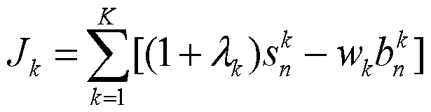

步骤 409: 根据所述优化线路速率、 最小 INP、 最大时延通过最大化成帧 规则获得实际净速率。
根据标准 G993.2中线路速率最大化成帧规则和最小 INP、 最大时延与线 路速率之间的关系, 将优化线路速率转化为实际净速率。
步骤 410: 判断当前迭代次数是否小于预先设置的最大迭代次数, 若是,
则执行步骤 411 ; 否则, 返回结束信息。
步骤 411 : 比较实际净速率与最小净速率的值, 若实际净速率大于最小净 速率, 且差值的绝对值大于预设的阔值, 则执行步骤 412; 若实际净速率小于 最小净速率, 且差值的绝对值大于预设的阔值, 则执行步骤 413; 若实际净速 率与最小净速率的差值的绝对值小于预设的阔值, 则执行步骤 414。
步骤 412: 置最大线路速率为实际净速率, 返回步骤 407。
步骤 413: 置最小线路速率为实际净速率, 返回步骤 407。
步骤 414: 根据实际净速率输出优化功率谱。
步骤 415: 通过最小二乘残差法将优化功率谱转化为发送功率功率谱整形 参数。
步骤 416: 保存功率谱整形参数和物理层目标参数作为用户功率优化后的 QoE模板。
步骤 417: 下发功率优化模板至用户对应的局端设备, 结束当前流程。
SMC 将功率优化模板通过局端设备的管理实体下发到局端设备的 MIB 中,在线路激活时局端设备的发送单元 xTU-C和用户端设备的发送单元 xTU-R 执行这些参数配置, 功率优化生效。
本发明基于 DSL的功率参数优化方法的另一个实施例流程如图 5所示, 该实施例示出了通过查表法获取实际净速率,以及釆用迭代方式获取优化功率 谱, 并将该优化功率谱与物理层目标参数进行合成下发的过程:
步骤 501 : 向 ISP发送获取用户的业务信息的请求, 并接收 ISP根据该请 求返回的用户的业务信息。
步骤 502: 根据各个业务信息对应的 QoE参数获取物理层目标参数。 步骤 503: 接收局端设备按照预先设置的时间间隔上报的用户的线路运行 信息。
步骤 504: 初始化最小线路速率为最小净速率, 最大线路速率为最大可达 速率, 并预先设置最大迭代次数。
步骤 505: 根据目标线路速率、 目标信噪比裕量、 测试参数和线路目标参 数执行功率优化算法后获取达到目标线路速率时最优发送功率谱、最小总功率 及对应的优化线路速率。
本实施例的功率优化算法与图 4所示的实施例一致, 在此不再赘述。
步骤 506: 根据所述优化线路速率、 最小 INP、 最大时延通过查找预先设 置的净速率数据表获得实际净速率。
与图 4所示的实施例不同在于, 本实施例中 SMC预先保存了根据线路速 率、 最小 INP和最大时延所得到的净速率数据表, 因此通过三者之间的关系, 通过查表即可获得优化线路速率对应的实际净速率。
步骤 507: 判断当前迭代次数是否小于预先设置的最大迭代次数, 若是, 则执行步骤 508; 否则, 返回结束信息。
步骤 508: 比较实际净速率与最小净速率的值, 若实际净速率大于最小净 速率, 且差值的绝对值大于预设的阔值, 则执行步骤 509; 若实际净速率小于 最小净速率, 且差值的绝对值大于预设的阔值, 则执行步骤 510; 若实际净速 率与最小净速率的差值的绝对值小于预设的阔值, 则执行步骤 511。
步骤 509: 置最大线路速率为实际净速率, 返回步骤 504。
步骤 510: 置最小线路速率为实际净速率, 返回步骤 504。
步骤 511 : 根据实际净速率输出优化功率谱。
步骤 512: 通过最小二乘残差法将所述优化功率谱转化为发送功率功率谱 整形参数。
步骤 513: 保存功率谱整形参数和物理层目标参数作为用户功率优化后的 QoE模板。
步骤 514: 下发功率优化模板至用户对应的局端设备, 结束当前流程。 本发明基于 DSL的功率参数优化方法的另一个实施例流程如图 6所示, 该实施例示出了根据输出优化功率谱后反馈的当前实际净速率进行迭代的过 程:
步骤 601 : 收集用户的业务信息,并根据各个业务信息对应的 QoE参数获 取物理层目标参数。
步骤 602: 接收用户的线路运行信息, 该线路运行信息包括测试参数和预 先存储的线路目标参数。
步骤 603: 初始化目标线路速率为最小净速率。
步骤 604: 根据目标线路速率、 目标信噪比裕量、 测试参数和线路目标参
数执行功率优化算法后获取达到目标线路速率时的最优发送功率谱、最小总功 率及对应的优化线路速率。
本实施例的功率优化算法与图 4所示的实施例一致, 在此不再赘述。 步骤 605: 根据优化线路速率向局端设备输出当前优化功率谱。
与图 4和图 5所示的实施例不同在于,本实施例中将通过一次迭代获得的 优化线路速率及生成的当前优化功率谱下发到局端设备中,由局端设备按照当 前优化功率谱执行相应的参数配置。
步骤 606: 接收局端设备执行该当前优化功率谱后反馈的当前实际净速 率。
局端设备执行当前的参数配置后,根据执行结果获得当前实际净速率, 将 该当前实际净速率反馈给 SMC,由 SMC进一步判断该当前实际净速率是否符 合 QoE要求。
步骤 607: 判断当前实际净速率是否小于最小净速率, 若是, 则执行步骤 608; 否则, 执行步骤 609。
步骤 608: 增大目标线路速率, 返回步骤 604。
在增大目标线路速率时, 可以按照下述方式获得新的目标线路速率, 即获 取最 d、净速率与该当前实际净速率的差,将该差与原始目标线路速率相加得到 新的目标线路速率, 然后把新的目标线路速率作为功率优化算法的输入参数, 执行步骤 604。
若当前实际净速率小于最小净速率,说明局端设备当前执行的参数配置不 符合 QoE要求, 需要重新执行最小化功率算法, 以及根据局端设备返回的实 际净速率进行进一步优化的过程。
步骤 609: 将该当前实际净速率作为用户线路的实际净速率, 结束流程。 若当前实际净速率大于最小净速率,说明局端设备当前执行的参数配置符 合 QoE要求, 将该当前实际净速率作为用户线路的实际净速率即可。
与本发明基于 DSL的功率优化方法的实施例相对应, 本发明还提供了基 于 DSL的功率优化系统的实施例。
本发明基于 DSL的功率优化系统的实施例的结构示意图如图 7所示, 该 系统包括: 网管设备 710和局端设备 710。
其中, 网管设备 710用于收集用户的业务信息,根据各个业务信息对应的 QoE参数获取物理层目标参数,接收所述局端设备 720上报的用户的线路运行 信息, 所述线路运行信息包括测试参数和预先存储的线路目标参数,将所述物 理层目标参数和所述线路运行信息作为功率优化算法的输入参数,通过功率优 化算法获取优化功率谱。
进一步,网管设备还可以用于通过最小二乘残差法将所述优化功率谱转化 为发送功率功率谱整形参数,保存所述功率谱整形参数和所述物理层目标参数 作为所述用户的功率优化模板,并下发所述功率优化模板至所述用户对应的局 端设备 720。
与本发明基于 DSL的功率优化方法和系统的实施例相对应, 本发明还提 供了基于 DSL的功率优化设备的实施例。
本发明基于 DSL的功率优化设备的一个实施例的结构示意图如图 8所示, 该设备包括: 物理层参数获取单元 810、 线路运行信息接收单元 820和优化功 率谱获取单元 830。
其中, 物理层参数获取单元 810用于收集用户的业务信息,根据各个业务 信息对应的 QoE参数获取物理层目标参数; 线路运行信息接收单元 820用于 接收所述用户的线路运行信息,所述线路运行信息包括测试参数和预先存储的 线路目标参数;优化功率谱获取单元 830用于将所述物理层目标参数和所述线 路运行信息作为功率优化算法的输入参数, 通过功率优化算法获取优化功率 谱。
本发明基于 DSL的功率优化设备的另一个实施例的结构示意图如图 9所 示, 该设备包括: 物理层参数获取单元 910、 线路运行信息接收单元 920和优 化功率谱获取单元 930。
其中, 物理层参数获取单元 910 , 用于收集用户的业务信息, 根据各个业 务信息对应的 QoE参数获取物理层目标参数。 在收集用户的业务信息时, 可 以接收按照预先设置的时间间隔下发的所述用户的业务信息,或者发送获取所 述用户的业务信息的请求, 并接收根据所述请求返回的所述用户的业务信息。 物理层参数获取单元 910具体包括:
QoE参数查找单元 911 , 用于查找预先存储的业务类型与 QoE参数的对
应关系, 获取所述各个业务信息对应的 QoE参数;
QoE参数比较单元 912, 用于比较不同业务的同种 QoE参数, 获得同种 QoE参数中值最大的 QoE参数;
物理层参数转化单元 913 ,用于根据 QoE参数与物理层目标参数的对应关 系将所有值最大的 QoE参数转化为物理层目标参数。
线路运行信息接收单元 920, 用于接收所述用户的线路运行信息, 所述线 路运行信息包括测试参数和预先存储的线路目标参数。在接收用户的线路运行 信息时,可以接收局端设备按照预先设置的时间间隔上报的所述用户的线路运 行信息, 或者向所述局端设备发送获取所述线路运行信息的请求, 并接收所述 局端设备返回的所述用户的线路运行信息。
优化功率谱获取单元 930包括:
参数初始化单元 931 , 用于初始化最小线路速率为所述最小净速率, 最大 线路速率为所述最大可达速率, 并预先设置最大迭代次数;
功率优化算法执行单元 932, 用于根据目标线路速率、 目标信噪比裕量、 测试参数和线路目标参数执行所述功率优化算法后获取达到目标线路速率时 的最小总功率及对应的优化线路速率,所述目标线路速率根据所述最小净速率 和最大线路速率获取;
实际净速率获取单元 933 , 用于根据所述优化线路速率、 最小 INP、 最大 时延通过最大化成帧规则获得实际净速率; 或根据所述优化线路速率、 最小 INP、 最大时延通过查找预先设置的净速率数据表获得实际净速率;
优化功率谱比较输出单元 934 , 用于比较所述实际净速率与所述最小净速 率,当两者差值的绝对值小于预先设置的阔值且当前迭代次数小于所述最大迭 代次数时, 根据所述实际净速率输出优化功率谱;
返回迭代单元 935, 用于当实际净速率大于最小净速率, 且两者差值的绝 对值大于预设的阔值, 并且当前迭代次数小于所述最大迭代次数时, 置所述最 大线路速率为所述实际净速率, 并返回所述参数初始化单元; 或当实际净速率 小于最小净速率, 且两者差值的绝对值大于预设的阔值, 并且当前迭代次数小 于所述最大迭代次数时, 置所述最小线路速率为所述实际净速率, 并返回所述 参数初始化单元;
结束信息返回单元 936, 用于当前迭代次数大于所述最大迭代次数时, 返 回结束信息。
本发明基于 DSL的功率优化设备的另一个实施例的结构示意图如图 10所 示, 该设备包括: 物理层参数获取单元 1010、 线路运行信息接收单元 1020和 优化功率谱获取单元 1030。
其中, 物理层参数获取单元 1010, 用于收集用户的业务信息, 根据各个 业务信息对应的 QoE参数获取物理层目标参数。 在收集用户的业务信息时, 可以接收按照预先设置的时间间隔下发的所述用户的业务信息,或者发送获取 所述用户的业务信息的请求, 并接收根据所述请求返回的所述用户的业务信 息。
线路运行信息接收单元 1020, 用于接收所述用户的线路运行信息, 所述 线路运行信息包括测试参数和预先存储的线路目标参数。在接收用户的线路运 行信息时,可以接收局端设备按照预先设置的时间间隔上报的所述用户的线路 运行信息, 或者向所述局端设备发送获取所述线路运行信息的请求, 并接收所 述局端设备返回的所述用户的线路运行信息。
优化功率谱获取单元 1030包括:
参数初始化单元 1031 , 用于初始化目标线路速率为所述最小净速率; 功率优化算法执行单元 1032, 用于根据所述目标线路速率、 目标信噪比 裕量、测试参数和线路目标参数执行所述功率优化算法后获取达到目标线路速 率时的最小总功率及对应的优化线路速率;
实际净速率反馈单元 1033 , 用于根据所述优化线路速率输出当前优化功 率谱, 并接收执行所述当前优化功率谱后反馈的当前实际净速率;
实际净速率确定单元 1034 , 用于判断所述当前实际净速率是否小于所述 步骤; 否则, 将所述当前实际净速率作为所述用户线路的实际净速率。
本发明基于 DSL的功率优化设备的另一个实施例框图如图 11所示,该设 备包括: 物理层参数获取单元 1110、 线路运行信息接收单元 1120、 优化功率 谱获取单元 1130、 整形参数获取单元 1140、 功率优化模板保存单元 1150和功 率优化模板下发单元 1160。
其中, 物理层参数获取单元 1110用于收集用户的业务信息, 根据各个业 务信息对应的 QoE参数获取物理层目标参数; 线路运行信息接收单元 1120用 于接收所述用户的线路运行信息,所述线路运行信息包括测试参数和预先存储 的线路目标参数; 优化功率谱获取单元 1130用于将所述物理层目标参数和所 述线路运行信息作为功率优化算法的输入参数,通过功率优化算法获取优化功 率谱; 整形参数获取单元 1140用于通过最小二乘残差法将所述优化功率谱转 化为发送功率功率谱整形参数; 功率优化模板保存单元 1150用于保存所述功 率谱整形参数和所述物理层目标参数作为所述用户的功率优化模板;功率优化 模板下发单元 1150用于下发所述功率优化模板至所述用户对应的局端设备。
通过本发明实施例的描述可知, 在应用本发明实施例进行 DSL参数优化 时, 由于按照 QoE对 DSL网络中的功率进行优化, 提升了用户体验, 并且釆 用最小功率法优化发射功率谱, 因此在满足 QoE的同时, 降低了总功率的消 耗, 减小了不同 DSL信号之间的串扰, 使得系统的信号传输稳定, 提高了业 务传输质量。
本领域普通技术人员可以理解实现上述实施例方法中的全部或部分步骤 是可以通过程序来指令相关的硬件来完成,所述的程序可以存储于一计算机可 读取存储介质中, 该程序在执行时, 包括如下步骤: 收集用户的业务信息, 根 据各个业务信息对应的 QoE参数获取物理层目标参数; 接收所述用户的线路 运行信息, 所述线路运行信息包括测试参数和预先存储的线路目标参数; 将所 述物理层目标参数和所述线路运行信息作为功率优化算法的输入参数,通过功 率优化算法获取优化功率谱。 所述的存储介质, 如: ROM/RAM、 磁碟、 光盘 等。
虽然通过实施例描绘了本发明, 本领域普通技术人员知道, 本发明有许多 变形和变化而不脱离本发明的精神,希望所附的权利要求包括这些变形和变化 而不脱离本发明的精神。
Claims
1、 一种基于数字用户线的功率优化方法, 其特征在于, 包括:
收集用户的业务信息, 并根据与所述业务信息对应的体验质量 QoE参数 获取物理层目标参数;
接收所述用户的线路运行信息;
将所述物理层目标参数和所述线路运行信息作为功率优化算法的输入参 数, 通过功率优化算法获取优化功率谱。
2、 根据权利要求 1所述的方法, 其特征在于, 所述根据与所述业务信息 对应的 QoE参数获取物理层目标参数包括:
查找预先存储的业务类型与 QoE参数的对应关系, 获取与所述业务信息 对应的 QoE参数;
比较所述业务信息中不同业务的同种 QoE参数, 获得所述不同业务的同 种 QoE参数中值最大的 QoE参数;
根据 QoE参数与物理层目标参数的对应关系将所述值最大的 QoE参数转 化为物理层目标参数。
3、 根据权利要求 1所述的方法, 其特征在于,
所述物理层目标参数包括: 最小净速率、 最小 INP、 最大时延、 目标信噪 比裕量的一种或多种组合;
所述线路运行信息包括: 测试参数和预先存储的线路目标参数。
4、 根据权利要求 3所述的方法, 其特征在于,
所述测试参数包括: 背景噪声和信道衰减;
所述预先存储的线路目标参数包括: 最大可达速率、最大功率和每个子频 段的最大功率。
5、 根据权利要求 4所述的方法, 其特征在于, 所述通过功率优化算法获 取优化功率谱包括:
初始化最小线路速率为所述最小净速率,最大线路速率为所述最大可达速 率, 并预先设置最大迭代次数;
根据目标线路速率、 目标信噪比裕量、 测试参数和线路目标参数执行所述 功率优化算法后获取达到所述目标线路速率时的优化线路速率,其中所述目标
线路速率根据所述最小线路速率和最大线路速率获取;
根据所述优化线路速率、 最小 INP、 最大时延通过最大化成帧规则获得实 际净速率;
比较所述实际净速率与所述最小净速率,当两者差值的绝对值小于预先设 置的阔值且当前迭代次数小于所述最大迭代次数时,根据所述实际净速率输出 优化功率谱。
6、 根据权利要求 4所述的方法, 其特征在于, 所述通过功率优化算法获 取优化功率谱包括:
初始化最小线路速率为所述最小净速率,最大线路速率为所述最大可达速 率, 并预先设置最大迭代次数;
根据目标线路速率、 目标信噪比裕量、 测试参数和线路目标参数执行所述 功率优化算法后获取达到所述目标线路速率时的优化线路速率, 其中, 所述目 标线路速率根据所述最小线路速率和最大线路速率获取;
根据所述优化线路速率、 最小 INP、 最大时延通过查找预先设置的净速率 数据表获得实际净速率;
比较所述实际净速率与所述最小净速率,当两者差值的绝对值小于预先设 置的阔值且当前迭代次数小于所述最大迭代次数时,根据所述实际净速率输出 优化功率谱。
7、 根据权利要求 5或 6所述的方法, 其特征在于, 还包括:
当实际净速率大于最小净速率, 且两者差值的绝对值大于预设的阔值, 并 且当前迭代次数小于所述最大迭代次数时,置所述最大线路速率为所述实际净 速率, 并返回所述初始化的步骤;
当实际净速率小于最小净速率, 且两者差值的绝对值大于预设的阔值, 并 且当前迭代次数小于所述最大迭代次数时,置所述最小线路速率为所述实际净 速率, 并返回所述初始化的步骤;
当前迭代次数大于所述最大迭代次数时, 返回结束信息。
8、 根据权利要求 4所述的方法, 其特征在于, 所述通过功率优化算法获 取优化功率谱包括:
初始化目标线路速率为所述最小净速率;
根据目标线路速率、 目标信噪比裕量、 测试参数和线路目标参数执行所述 功率优化算法后获取达到目标线路速率时的优化线路速率;
根据所述优化线路速率输出当前优化功率谱,并接收执行所述当前优化功 率谱后反馈的当前实际净速率;
判断所述当前实际净速率是否小于所述最小净速率, 若是, 则增大所述目 标线路速率并返回所述执行功率优化算法的步骤; 否则,将所述当前实际净速 率作为所述用户线路的实际净速率。
9、 根据权利要求 1所述的方法, 其特征在于, 还包括:
通过最小二乘残差法将所述优化功率谱转化为发送功率功率谱整形参数; 保存所述功率谱整形参数和所述物理层目标参数作为所述用户的功率优 化模板;
下发所述功率优化模板至所述用户对应的局端设备。
10、 一种基于数字用户线的功率优化系统, 其特征在于, 包括: 网管设备 和局端设备,
所述网管设备, 用于收集用户的业务信息, 根据与所述业务信息对应的
QoE 参数获取物理层目标参数, 接收所述局端设备上报的用户的线路运行信 息, 将所述物理层目标参数和所述线路运行信息作为功率优化算法的输入参 数, 通过功率优化算法获取优化功率谱。
11、 根据权利要求 10所述的系统, 其特征在于, 所述网管设备还用于, 通过最小二乘残差法将所述优化功率谱转化为发送功率功率谱整形参数,保存 所述功率谱整形参数和所述物理层目标参数作为所述用户的功率优化模板,并 下发所述功率优化模板至所述用户对应的局端设备。
12、 一种基于数字用户线的功率优化设备, 其特征在于, 包括: 物理层参数获取单元, 用于收集用户的业务信息, 并根据与所述业务信息 对应的 QoE参数获取物理层目标参数;
线路运行信息接收单元, 用于接收所述用户的线路运行信息;
优化功率谱获取单元,用于将所述物理层目标参数和所述线路运行信息作 为功率优化算法的输入参数, 通过功率优化算法获取优化功率谱。
13、 根据权利要求 12所述的设备, 其特征在于, 所述物理层参数获取单
元包括:
QoE参数查找单元, 用于查找预先存储的业务类型与 QoE参数的对应关 系, 获取与所述业务信息对应的 QoE参数;
QoE参数比较单元,用于比较所述业务信息中不同业务的同种 QoE参数, 获得所述不同业务的同种 QoE参数中值最大的 QoE参数;
物理层参数转化单元, 用于根据 QoE参数与物理层目标参数的对应关系 将所述值最大的 QoE参数转化为物理层目标参数。
14、 根据权利要求 12所述的设备, 其特征在于, 还包括:
整形参数获取单元,用于通过最小二乘残差法将所述优化功率谱转化为发 送功率功率谱整形参数;
功率优化模板保存单元,用于保存所述功率谱整形参数和所述物理层目标 参数作为所述用户的功率优化模板;
功率优化模板下发单元,用于下发所述功率优化模板至所述用户对应的局 端设备。
Priority Applications (2)
| Application Number | Priority Date | Filing Date | Title |
|---|---|---|---|
| EP09807824.9A EP2309655B1 (en) | 2008-08-18 | 2009-04-21 | Method, system and device for power optimization based on digital subscriber line |
| US13/028,679 US8396140B2 (en) | 2008-08-18 | 2011-02-16 | Method, system, and device for power optimization based on digital subscriber line |
Applications Claiming Priority (2)
| Application Number | Priority Date | Filing Date | Title |
|---|---|---|---|
| CN200810145881.0 | 2008-08-18 | ||
| CN200810145881.0A CN101345552B (zh) | 2008-08-18 | 2008-08-18 | 基于数字用户线的功率优化方法、系统及设备 |
Related Child Applications (1)
| Application Number | Title | Priority Date | Filing Date |
|---|---|---|---|
| US13/028,679 Continuation US8396140B2 (en) | 2008-08-18 | 2011-02-16 | Method, system, and device for power optimization based on digital subscriber line |
Publications (1)
| Publication Number | Publication Date |
|---|---|
| WO2010020125A1 true WO2010020125A1 (zh) | 2010-02-25 |
Family
ID=40247458
Family Applications (1)
| Application Number | Title | Priority Date | Filing Date |
|---|---|---|---|
| PCT/CN2009/071378 Ceased WO2010020125A1 (zh) | 2008-08-18 | 2009-04-21 | 基于数字用户线的功率优化方法、系统及设备 |
Country Status (4)
| Country | Link |
|---|---|
| US (1) | US8396140B2 (zh) |
| EP (1) | EP2309655B1 (zh) |
| CN (1) | CN101345552B (zh) |
| WO (1) | WO2010020125A1 (zh) |
Families Citing this family (10)
| Publication number | Priority date | Publication date | Assignee | Title |
|---|---|---|---|---|
| US8098054B2 (en) * | 2007-10-10 | 2012-01-17 | John Alexander Verschuur | Optimal load controller method and device |
| CN101345552B (zh) * | 2008-08-18 | 2013-06-05 | 华为技术有限公司 | 基于数字用户线的功率优化方法、系统及设备 |
| CN102055617B (zh) * | 2009-11-03 | 2013-01-02 | 华为技术有限公司 | 监控dsl用户板功耗值的方法、装置及dsl用户板 |
| CN103095337B (zh) * | 2011-10-28 | 2016-08-03 | 中兴通讯股份有限公司 | 提高消除串扰稳定性方法、装置及局端 |
| CN103312531B (zh) | 2012-03-15 | 2017-02-22 | 华为技术有限公司 | 一种获取qoe的方法、装置及保证qoe的方法、装置 |
| US9317212B2 (en) | 2012-12-18 | 2016-04-19 | Intel Corporation | Method and apparatus for controlling a storage device |
| EP3123670B1 (en) | 2014-03-24 | 2018-03-28 | British Telecommunications public limited company | Dynamic line management |
| CN104113864A (zh) * | 2014-07-30 | 2014-10-22 | 中国联合网络通信集团有限公司 | 一种网络自优化的方法、装置 |
| CA3050022C (en) | 2017-01-26 | 2023-01-24 | Telefonaktiebolaget Lm Ericsson (Publ) | Methods and apparatuses for power control in a wireless communication system |
| CN110718087B (zh) * | 2018-07-11 | 2021-03-09 | 北京嘀嘀无限科技发展有限公司 | 数据融合处理方法及装置 |
Citations (3)
| Publication number | Priority date | Publication date | Assignee | Title |
|---|---|---|---|---|
| CN1852038A (zh) * | 2005-07-07 | 2006-10-25 | 华为技术有限公司 | 专用信道重配后的初始发射功率优化方法 |
| CN101166046A (zh) * | 2006-10-19 | 2008-04-23 | 中兴通讯股份有限公司 | 一种数字用户线dsl功率控制方法及其控制系统 |
| CN101345552A (zh) * | 2008-08-18 | 2009-01-14 | 华为技术有限公司 | 基于数字用户线的功率优化方法、系统及设备 |
Family Cites Families (20)
| Publication number | Priority date | Publication date | Assignee | Title |
|---|---|---|---|---|
| US6175550B1 (en) * | 1997-04-01 | 2001-01-16 | Lucent Technologies, Inc. | Orthogonal frequency division multiplexing system with dynamically scalable operating parameters and method thereof |
| WO1999020027A2 (en) * | 1997-10-10 | 1999-04-22 | Aware, Inc. | Splitterless multicarrier modem |
| US6084917A (en) * | 1997-12-16 | 2000-07-04 | Integrated Telecom Express | Circuit for configuring and dynamically adapting data and energy parameters in a multi-channel communications system |
| EP1161820B1 (en) * | 1999-03-12 | 2006-04-19 | Aware, Inc. | Seamless rate adaptive multicarrier modulation system and protocols |
| DE60233603D1 (de) * | 2001-01-16 | 2009-10-15 | Daphimo Co B V Llc | Schnelle Initialisierung unter Verwendung von "seamless rate" Adaptation |
| US7133419B1 (en) * | 2001-05-04 | 2006-11-07 | Conexant, Inc. | System and method for reducing power consumption by spectral shaping of signals |
| AU2003224007A1 (en) * | 2002-03-21 | 2003-10-08 | International Business Machines Corporation | Method and systems for optimizing adsl connections in dsl access multiplexor |
| ATE457574T1 (de) * | 2003-08-21 | 2010-02-15 | Vidiator Entpr Inc | Metriken für die qualität der erfahrung (qoe) für drahtlose kommunikationsnetze |
| US7302379B2 (en) * | 2003-12-07 | 2007-11-27 | Adaptive Spectrum And Signal Alignment, Inc. | DSL system estimation and parameter recommendation |
| JP4891779B2 (ja) | 2003-12-07 | 2012-03-07 | アダプティブ スペクトラム アンド シグナル アラインメント インコーポレイテッド | 適応マージン制御及び適応帯域制御 |
| KR101181174B1 (ko) * | 2005-01-26 | 2012-09-18 | 삼성전자주식회사 | 푸쉬투토크 오버 셀룰러 시스템 사용자의 단말 교체시세션 지속 보장 방법 및 그 시스템 |
| US7852952B2 (en) * | 2005-06-10 | 2010-12-14 | Adaptive Spectrum And Signal Alignment, Inc. | DSL system loading and ordering |
| CN100372364C (zh) | 2005-11-28 | 2008-02-27 | 华为技术有限公司 | 一种视频信号采集设备 |
| US7813293B2 (en) * | 2006-05-12 | 2010-10-12 | John Papandriopoulos | Method for distributed spectrum management of digital communications systems |
| US20070299746A1 (en) * | 2006-06-22 | 2007-12-27 | International Business Machines Corporation | Converged tool for simulation and adaptive operations combining it infrastructure performance, quality of experience, and finance parameters |
| US20080039097A1 (en) * | 2006-08-09 | 2008-02-14 | Seshadri Sathyanarayan | Intelligent IP Services Edge with Dynamic QOS to individually and collectively enhance subscribers quality of experience (QOE) in Wireless Broadband Networks |
| CN101237317B (zh) * | 2006-11-27 | 2010-09-29 | 华为技术有限公司 | 确定发送频谱的方法和装置 |
| CN1976440B (zh) | 2006-12-11 | 2011-03-30 | 中山大学 | 一种在iptv中精确定位播放进度的方法及系统 |
| US7864697B2 (en) * | 2007-08-03 | 2011-01-04 | John Papandriopoulos | Adapted method for spectrum management of digital communication systems |
| US8009749B2 (en) * | 2007-12-04 | 2011-08-30 | Lantiq Deutschland Gmbh | Method of transmission power control and communication device |
-
2008
- 2008-08-18 CN CN200810145881.0A patent/CN101345552B/zh not_active Expired - Fee Related
-
2009
- 2009-04-21 WO PCT/CN2009/071378 patent/WO2010020125A1/zh not_active Ceased
- 2009-04-21 EP EP09807824.9A patent/EP2309655B1/en not_active Not-in-force
-
2011
- 2011-02-16 US US13/028,679 patent/US8396140B2/en not_active Expired - Fee Related
Patent Citations (3)
| Publication number | Priority date | Publication date | Assignee | Title |
|---|---|---|---|---|
| CN1852038A (zh) * | 2005-07-07 | 2006-10-25 | 华为技术有限公司 | 专用信道重配后的初始发射功率优化方法 |
| CN101166046A (zh) * | 2006-10-19 | 2008-04-23 | 中兴通讯股份有限公司 | 一种数字用户线dsl功率控制方法及其控制系统 |
| CN101345552A (zh) * | 2008-08-18 | 2009-01-14 | 华为技术有限公司 | 基于数字用户线的功率优化方法、系统及设备 |
Non-Patent Citations (1)
| Title |
|---|
| See also references of EP2309655A4 * |
Also Published As
| Publication number | Publication date |
|---|---|
| EP2309655A4 (en) | 2012-01-18 |
| EP2309655B1 (en) | 2014-06-11 |
| EP2309655A1 (en) | 2011-04-13 |
| CN101345552A (zh) | 2009-01-14 |
| US20110135017A1 (en) | 2011-06-09 |
| CN101345552B (zh) | 2013-06-05 |
| US8396140B2 (en) | 2013-03-12 |
Similar Documents
| Publication | Publication Date | Title |
|---|---|---|
| CN101345552B (zh) | 基于数字用户线的功率优化方法、系统及设备 | |
| US10063278B2 (en) | Reducing the feedback overhead during crosstalk precoder initialization | |
| WO2008052485A1 (fr) | Procédé et dispositif de gestion du spectre de fréquences | |
| CN101610102B (zh) | 一种优化功率的方法、系统和装置 | |
| US20110007623A1 (en) | Method for Estimating the Strength of a Crosstalk Channel | |
| US7782930B2 (en) | Optimized short initialization after low power mode for digital subscriber line (DSL) communications | |
| WO2012126411A2 (zh) | 数字用户线的信号处理方法、装置及数字用户线系统 | |
| US8243844B2 (en) | Power reduction for digital subscriber line | |
| US9258790B2 (en) | Dynamic power spectrum management method, spectrum optimization system and client device | |
| US6732281B1 (en) | System and method for loading data onto carriers | |
| WO2009076882A1 (zh) | 一种分离器的检测方法、装置和系统 | |
| US7778346B2 (en) | Upstream power cutback | |
| CN101729094B (zh) | 数字用户线中上行功率下调方法、装置及系统 | |
| US8811600B2 (en) | Optimizing the transmit power spectrum density (PSD) of a remotely deployed line to ensure spectral compatibility | |
| CN101741426B (zh) | 一种提高dsl线路稳定性的方法、装置及系统 | |
| CN102318208B (zh) | 降低数字用户线业务传输中线间串扰的方法、装置及系统 | |
| CN101119134B (zh) | 一种控制线路通讯质量的方法 | |
| CN1731782B (zh) | 用于数据流质量控制的方法、相关接收器及相关发送器 | |
| WO2009152704A1 (zh) | 一种信道估计方法、装置和系统 | |
| CN101662311A (zh) | 一种提高频谱控制稳定性的方法、系统及装置 |
Legal Events
| Date | Code | Title | Description |
|---|---|---|---|
| 121 | Ep: the epo has been informed by wipo that ep was designated in this application |
Ref document number: 09807824 Country of ref document: EP Kind code of ref document: A1 |
|
| NENP | Non-entry into the national phase |
Ref country code: DE |
|
| WWE | Wipo information: entry into national phase |
Ref document number: 2009807824 Country of ref document: EP |