WO2010024148A1 - 飲料用容器の蓋 - Google Patents
飲料用容器の蓋 Download PDFInfo
- Publication number
- WO2010024148A1 WO2010024148A1 PCT/JP2009/064422 JP2009064422W WO2010024148A1 WO 2010024148 A1 WO2010024148 A1 WO 2010024148A1 JP 2009064422 W JP2009064422 W JP 2009064422W WO 2010024148 A1 WO2010024148 A1 WO 2010024148A1
- Authority
- WO
- WIPO (PCT)
- Prior art keywords
- cut
- straw
- lid
- cut portion
- cut portions
- Prior art date
- Legal status (The legal status is an assumption and is not a legal conclusion. Google has not performed a legal analysis and makes no representation as to the accuracy of the status listed.)
- Ceased
Links
Images





Classifications
-
- B—PERFORMING OPERATIONS; TRANSPORTING
- B65—CONVEYING; PACKING; STORING; HANDLING THIN OR FILAMENTARY MATERIAL
- B65D—CONTAINERS FOR STORAGE OR TRANSPORT OF ARTICLES OR MATERIALS, e.g. BAGS, BARRELS, BOTTLES, BOXES, CANS, CARTONS, CRATES, DRUMS, JARS, TANKS, HOPPERS, FORWARDING CONTAINERS; ACCESSORIES, CLOSURES, OR FITTINGS THEREFOR; PACKAGING ELEMENTS; PACKAGES
- B65D47/00—Closures with filling and discharging, or with discharging, devices
- B65D47/04—Closures with discharging devices other than pumps
- B65D47/06—Closures with discharging devices other than pumps with pouring spouts or tubes; with discharge nozzles or passages
-
- B—PERFORMING OPERATIONS; TRANSPORTING
- B65—CONVEYING; PACKING; STORING; HANDLING THIN OR FILAMENTARY MATERIAL
- B65D—CONTAINERS FOR STORAGE OR TRANSPORT OF ARTICLES OR MATERIALS, e.g. BAGS, BARRELS, BOTTLES, BOXES, CANS, CARTONS, CRATES, DRUMS, JARS, TANKS, HOPPERS, FORWARDING CONTAINERS; ACCESSORIES, CLOSURES, OR FITTINGS THEREFOR; PACKAGING ELEMENTS; PACKAGES
- B65D47/00—Closures with filling and discharging, or with discharging, devices
- B65D47/36—Closures with frangible parts adapted to be pierced, torn or removed, to provide discharge openings
-
- B—PERFORMING OPERATIONS; TRANSPORTING
- B65—CONVEYING; PACKING; STORING; HANDLING THIN OR FILAMENTARY MATERIAL
- B65D—CONTAINERS FOR STORAGE OR TRANSPORT OF ARTICLES OR MATERIALS, e.g. BAGS, BARRELS, BOTTLES, BOXES, CANS, CARTONS, CRATES, DRUMS, JARS, TANKS, HOPPERS, FORWARDING CONTAINERS; ACCESSORIES, CLOSURES, OR FITTINGS THEREFOR; PACKAGING ELEMENTS; PACKAGES
- B65D2231/00—Means for facilitating the complete expelling of the contents
- B65D2231/02—Precut holes or weakened zones
- B65D2231/022—Precut holes or weakened zones for permitting the insertion of a tubular contents-removing device, e.g. a drinking straw
Definitions
- the present invention relates to a lid for sealing a container opening filled with fluid food and drink. More specifically, the present invention relates to a lid structure that is a resin lid and can be easily pierced with a straw or the like.
- Beverages or fluid foods and drinks can be poured (ingested) into other containers from the opening of the container, or can be drunk directly with a mouth attached to the opening of the container.
- a straw or the like can be pierced and penetrated into the lid to be sealed, and the lid can be drunk.
- beverages or fluid foods and drinks for example, often have a plastic container covered with an aluminum cap (a laminate of an aluminum foil and a resin). Therefore, it was easy to stab a straw or the like and suck the contents (fluid food or drink) with a straw.
- Patent Document 1 a technique has been proposed in which the lid of the container is made of a synthetic resin, and the synthetic resin material in the portion where the straw is pierced is thinned to facilitate the piercing of the straw.
- the property that the lid of the container should satisfy is required not to be damaged even if a slight impact is applied.
- impact may be applied at the stage when the covered container is transported in large quantities, and the container in the state before the lid is removed after the general user fills the contents. This is because it is assumed that it will be dropped.
- Patent Document 1 since the synthetic resin material of the portion that pierces the straw is thinned, when the impact is applied from the outside, the thinned portion is damaged and the contents leak out. There is a risk that.
- the lid is made of a synthetic resin like a container, and a straw can be easily stabbed into the synthetic resin lid, Moreover, it is an object of the present invention to provide a lid for a beverage container so that the beverage as a content does not leak even when an impact is applied.
- the invented portion (the area for straw piercing / straw) Attention was paid to the fact that the strength of the hole portion: 20) was reduced and the straw (14) could be pierced into the lid (10) and penetrated easily. Further, in order to prevent the crack from progressing in the lid (10), the representative dimension of the straw piercing region (the straw hole portion 20) (for example, the diameter of the circular straw hole portion 20) is a predetermined value. It has been found that it is effective to reduce the length of the portion (half-cut portion) subjected to the above-mentioned “half-cut processing” to a certain value or less, while keeping it below.
- the lid of the beverage container of the present invention is entirely formed of a synthetic resin (R), and a substantially circular straw stab in a part (for example, the center) thereof.
- Region (straw hole portion 20) is provided, and the straw piercing region (20) has a depth of 1/4 to 1/2 (preferably about 1/3) of the thickness of the synthetic resin material.
- a plurality of cut portions (half cut Hc) are formed, the diameter (R1 ⁇ 2) of the straw piercing region (20) is 8.0 mm or less (preferably 7.0 mm or less), and the cut portion (half cut Hc) ) Is 3.0 mm or less (preferably 2.5 mm or less) (Claim 1).
- the straw piercing region (20) includes an arc-shaped cut portion (half cut portions C1, C2, C3) that defines a virtual circle of the outermost shell of the straw piercing region (20),
- the virtual circle (the virtual circle defined by the half-cut portions C1, C2, and C3) is formed in the inner region of the virtual circle defined by the arc-shaped cut portions (half-cut portions C1, C2, and C3).
- a first straight cut portion (half cut portions TL1, TL2, TL3) defining a virtual equilateral triangle whose center of gravity coincides with the center of the virtual circle (the center of the unhalf cut portion BCC).
- a second straight cut portion (half cut portion) extending outward in the radial direction of the virtual circle from the center of the virtual circle (the center of the non-half cut portion BCC) LC1, TLC2, TLC3) and the first linear cut portions (half cut portions TL1, TL2, TL3) and the second linear cut portions (half cut portions TLC1, TLC2, TLC3)
- a third linear cut portion (half cut portions TLM1, TLM2, TLM3) extending in parallel with one straight cut portion (half cut portions TL1, TL2, TL3) is formed (claims). 2).
- a cut portion (half cut Hc) is formed in a region (UHc1, UHc2, UHc3) obtained by extending the second linear cut portion (half cut portions TLC1, TLC2, TLC3) radially outward. Preferably, it is not done (Claim 3).
- the arc-shaped cut portions (half cut portions C1 to C3) and the first linear cut portions (half cut portions TL1 to TL3) are regions where the cut portions are not formed (unhalf cut portions C1B). , C2B, C3B, TL1B, TL2B, TL3B). (Claim 4)
- the straw piercing region (20) has a cut portion having a depth of 1/4 to 1/2 (preferably about 1/3) of the thickness of the synthetic resin material. Since a plurality of (half-cut Hc) are formed, even if the lid (10) made of synthetic resin (R), if it is a straw piercing region (20), it can be pierced easily by the straw (14). I can do it.
- the depth of the cut portion (half cut Hc) is 1/4 to 1/2 (preferably about 1/3) of the thickness of the synthetic resin material, and the diameter of the straw piercing region (20) ( R1 ⁇ 2) is 8.0 mm or less (preferably 7.0 mm or less), and the length of the cut portion (half cut Hc) is 3.0 mm or less (preferably 2.5 mm or less). Even when an impact is applied to (12) or when pierced with a straw (14), the lid (10) or the straw piercing area (20) is cracked or cracked from the cut portion (half cut Hc). Is prevented from progressing.
- the lid (10) made of a synthetic resin (R) that does not leak contents even when an impact is applied and can be easily pierced by a straw (14). Is provided.
- an arc-shaped cut portion (half cut portion C1, C2, C3) that defines a virtual circle of the outermost shell of the straw piercing region (20) is provided (Claim 2)
- the same force is provided.
- the outermost shell of the straw piercing area (20) which is the area where the straw (14) is pierced, is defined, and the center of the virtual circle, which is the target location for piercing the straw (14), can be easily and reliably determined visually. Can be determined.
- the vertex is located outside the virtual circle (the virtual circle defined by the half-cut portions C1, C2, and C3) and the center of gravity is the center of the virtual circle (the center of the unhalf-cut portion BCC).
- the first straight cut portions half cut portions TL1, TL2, TL3), the first straight cut portions (half cut portions TL1, TL2, TL3) and the second defining virtual equilateral triangles that coincide with each other
- a third straight cut portion extending in parallel with the first straight cut portion (half cut portions TL1, TL2, TL3) in a region between the straight cut portions (half cut portions TLC1, TLC2, TLC3).
- a cut portion (half cut Hc) is formed in a region (UHc1, UHc2, UHc3) obtained by extending the second linear cut portion (half cut portions TLC1, TLC2, TLC3) radially outward. If not (Claim 3), when the straw piercing region (20) is pierced by the straw (14), the synthetic resin is torn at the cut portion (half cut Hc), and the cut portion (half cut Hc) Even if the region (DP) surrounded by (2) hangs downward, the regions (UHc1, UHc2, UHc3) extending outward in the radial direction remain in the lid (10), and therefore are surrounded by the cut portion (half cut Hc). The separated area (DP) does not fall off the lid (10). Therefore, it is prevented that the region (DP) surrounded by the cut portion (half cut Hc) is mixed into the beverage. (See FIG. 9).
- the arc-shaped cut portions (half cut portions C1 to C3) and the first linear cut portions (half cut portions TL1 to TL3) are regions where the cut portions are not formed (unhalf). If it is separated by the cut portions C1B, C2B, C3B, TL1B, TL2B, TL3B (Claim 4), the length of the cut portion (half cut Hc) is 3.0 mm or less (preferably 2.5 mm or less). The condition can be satisfied.
- the perspective view which shows the outline
- the elements on larger scale which show the cut
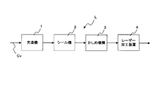
- Explanatory drawing which shows the line which manufactures the container sealed with the lid concerning embodiment.
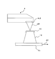
- Explanatory drawing which shows the outline
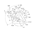
- the enlarged view which shows the detail of the cut
- FIG. 6 is an enlarged view for explaining the positional relationship between a cut portion and a straw tip shown in FIG. 5.
- the cover according to the embodiment of the present invention is generally indicated by reference numeral 10, and covers the opening of the beverage container 12 (the upper end of the container 12 in FIG. 1).
- the lid 10 is entirely made of only synthetic resin and does not include an aluminum foil as a base material.
- synthetic resin such as PS (polystyrene) resin, AS (styrene-acrylonitrile copolymer) resin, ABS (acrylonitrile-butadiene-styrene copolymer) resin, AXS resin (terpolymer having acrylonitrile and styrene component), etc.
- FIG. 1 shows a state where the straw 14 is about to be pierced into the lid 10, and the tip of the straw 14 moves toward a straw piercing region (straw hole portion) 20 provided at the center of the lid 10. ing.
- the straw hole portion 20 is formed by forming a plurality of cut portions, that is, half-cut Hc, in the synthetic resin material constituting the lid 10.
- FIG. 2 shows a state where the half-cut Hc is applied to the synthetic resin material R constituting the lid 10.
- the half cut Hc is a cross section obtained by cutting the synthetic resin material R to a depth D of about 1 ⁇ 4 to about 1 ⁇ 2, preferably about 3 of the thickness direction dimension t. It is formed as a triangular notch.
- the depth D of the half cut Hc is set to about 60 ⁇ m (about 1/3 with respect to the thickness of the material of the lid 10). Yes.
- FIG. 3 shows an outline of a system for forming the straw hole portion 20 by forming the half cut Hc on the lid 10 of the beverage container 12.
- a line for producing a product in which a predetermined content is filled in a beverage container and properly sealed is indicated by the symbol L as a whole, and the transport for transporting the beverage container 12 is carried out.
- An apparatus for example, a belt conveyor
- the conveying device Cv is provided with a filling machine 1, a sealing machine 2, a caulking mechanism 3, and a laser processing device 4.
- an empty beverage container 12 is filled with a predetermined amount of beverage. And the opening part of the container 12 filled with the beverage is sealed with a lid made of synthetic resin in the sealing machine 2.
- the synthetic resin lid simply covers the opening of the container 12, but in the caulking mechanism 3, the edge 10E of the lid (see FIG. 1) is the container. 12 is bent so as to be along the upper edge (opening side edge) of the side surface portion, and as shown in FIG. 1, it covers the opening of the container 12 so as to surround it.
- Known devices can be applied to the filling machine 1, the sealing machine 2, and the caulking mechanism 3.
- the beverage container conveys the place where the laser processing device 4 is provided.
- the laser processing apparatus 4 a known and commercially available apparatus for laser processing (for example, a three-dimensional control CO2 laser marker manufactured and sold by Keyence Corporation, trade name “ML-Z9500”) can be used. With this laser processing device 4, a half cut Hc is formed on the surface of the lid 10 made of synthetic resin so as to surround the opening of the beverage container 12.
- FIG. 4 shows a state in which the half-cut Hc is formed on the lid 10 that covers the opening of the beverage container 12 by the laser processing device 4.
- a laser beam for example, CO 2 laser beam
- the conveying device Cv continues to move in the direction indicated by the arrow AC, and continuously moves while the half cut Hc is formed on the lid 10.
- the transport device Cv continuously moves in the direction of the arrow AC, and does not stop when the half cut Hc is formed.
- the laser processing apparatus 4 forms the half cut Hc exactly as a desired shape with respect to the object (For example, the lid
- FIG. 5 shows a straw hole portion 20 formed by forming a half cut Hc by the laser processing apparatus 4 in the illustrated embodiment.
- each curved portion or straight portion where the half cut Hc is formed is referred to as a “half cut portion”.
- a portion where the half cut Hc is not formed is referred to as an “unhalf cut portion”.
- the straw hole portion 20 has three curved half-cut portions C1, C2, and C3 (arc-shaped cut portions) provided to form an arc on the outer edge portion.
- the three curved half-cut portions C1, C2, and C3 are formed so as to define a virtual circle of the outermost shell of the straw hole portion 20.
- the curved or arcuate half-cut portion C1 is separated into curved or arcuate portions C11 and C12 by a portion (unhalf-cut portion) C1B that is not half-cut.
- the arc-shaped half-cut portion C2 is separated into arc-shaped portions C21 and C22 by the non-half-cut portion C2B
- the arc-shaped half-cut portion C3 is divided into the arc-shaped portions C31 and C32 by the non-half-cut portion C3B. It is separated.
- linear half-cut portions TL1 and TL2 arranged to form three sides of an equilateral triangle inside a circle (imaginary circle) formed by the arc-shaped half-cut portions C1 to C3.
- TL3 first linear cut portion half cut portion is formed.
- the linear half-cut portions TL1, TL2, and TL3 are arranged so as to form a shape in which the three vertices of the regular triangle are omitted.
- the straight half-cut portions TL1, TL2, and TL3 define equilateral triangles (virtual equilateral triangles) whose apexes are located outside the virtual circle defined by the arc-shaped half-cut portions C1, C2, and C3. .
- the center of gravity of the virtual equilateral triangle defined by the linear half-cut portions TL1, TL2, and TL3 coincides with the center of the virtual circle defined by the arc-shaped half-cut portions C1, C2, and C3.
- the center of the virtual equilateral triangle or the center of the virtual circle is also the center of the unhalf-cut portion BBC.
- the center of the virtual equilateral triangle, the center of the virtual circle, or the center of the non-half-cut portion BBC is shown with a reference numeral to prevent the drawing from becoming complicated.
- the non-half-cut portion BBC is a small region, in this specification, the center of the virtual equilateral triangle or the center of the virtual circle may be expressed by the symbol BCC for the sake of simplicity.
- the straight half-cut portion TL1 is separated into straight portions TL11 and TL12 by the non-half-cut portion TL1B.
- the straight half-cut portion TL2 is separated into straight portions TL21 and TL22 by the non-half-cut portion TL2B
- the straight half-cut portion TL3 is separated by the non-half-cut portion TL3B. Separated into TL32.
- the half cut portion TLC1 is arranged on a bisector (virtual line) of an angle formed by the half cut portions TL1 and TL3.
- Half cut part TLC2 is arranged on the bisector (imaginary line) of the angle which half cut parts TL1 and TL2 form.
- Half cut part TLC3 is arranged on a bisector (imaginary line) of an angle which half cut parts TL2 and TL3 form.
- symbol ETLC1 is the end of the half-cut portion TLC1 on the equilateral triangle apex side (opposite the center of the circle formed by C1 to C3)
- symbol ETLC2 is the equilateral triangle apex side of the half-cut portion TLC2 ( C1-C3 is the end of the circle that is opposite to the center of the circle)
- ETLC3 is the end of the half-cut portion TLC3 on the equilateral triangle apex side (opposite to the center of the circle that is formed by C1-C3) It is.
- the center of the circle formed by the arc-shaped half cut portions C1 to C3 and the center of gravity of the regular triangle formed by the straight half cut portions TL1, TL2, and TL3 coincide with each other.
- the three straight half-cut portions TLC1, TLC2, and TLC3 are the center of the circle formed by the arc-shaped half-cut portions C1 to C3 (or the equilateral triangle formed by the half-cut portions TL1, TL2, and TL3). In the center of gravity), it is separated by an unhalf-cut portion BCC.
- the center of the circle formed by the arc-shaped half-cut portions C1 to C3 or the center of gravity of the regular triangle formed by the straight half-cut portions TL1 to TL3 is the non-half-cut portion BCC.
- the region between the three straight half-cut portions TLC1 to TLC3 extending so as to connect the center of the regular triangle formed by TL1, TL2, and TL3 and each vertex of the regular triangle there are three straight lines.
- Shaped half-cut portions TLM1, TLM2, and TLM3 are formed.
- the linear half-cut portion TLM1 is formed in parallel with the half-cut portion TL1 in an isosceles triangular region composed of the linear half-cut portions TL1, TLC1, and TLC2.
- the straight half-cut portion TLM2 is formed in parallel with the half-cut portion TL2 in an isosceles triangular region composed of the straight half-cut portions TL2, TLC2, and TLC3.
- the straight half-cut portion TLM3 is formed in parallel with the half-cut portion TL3 in an isosceles triangular region composed of the straight half-cut portions TL3, TLC3, and TLC1.
- Arc-shaped half-cut portions C1, C2, and C3 (half-cut portions that form a circle) described above, linear half-cut portions TL1, TL2, and TL3 (half-cut portions that form an equilateral triangle), three linear shapes Half-cut portions TLC1, TLC2, TLC3 (half-cut portions extending radially outward from the center of the circle), three linear half-cut portions TLM1, TLM2, TLM3 (TL1-TL3 and TLC1-TLC3)
- the half-cut portions formed in the region between each other are not continuous with the other half-cut portions, and are formed at the center position of the lid 10 in an independent state.
- the radius of curvature of the arc-shaped portion C11 is indicated by reference numeral R1, and the radius of curvature R1 is set to 3 mm, for example.
- the radius of curvature R1 is the radius of curvature of the circle formed by the arc-shaped half-cut portions C1, C2, and C3, and the arc-shaped half-cut portions C1, C2, and C3 and the portions C11, C12, C21, Common to C22, C31, and C32.
- Reference symbol R2 is a radius of curvature of a virtual circle RE formed by connecting the apex-side end portions ETLC1, ETLC2, and ETLC3 of the regular triangle in each of the linear half-cut portions TLC1 to TLC3, for example, 2.5 mm.
- the entire virtual circle RE is not shown, and only a virtual arc that virtually connects the end ETLC1 of the half-cut portion TLC1 and the end ETLC2 of the half-cut portion TLC2 is shown.
- the center of the circle formed by the arc-shaped half-cut portions C1 to C3 or the center of gravity of the regular triangle formed by the straight half-cut portions TLC1 to TLC3 is the non-half-cut portion BCC as described above.
- the diameter of the non-half-cut portion BCC is indicated by the symbol ⁇ 1, for example, 0.1 mm.
- ⁇ 1 is the diameter of an imaginary circle connecting the ends of the three circles TLC1 to TLC3 on the center side (center of gravity of the regular triangle) of the circle.
- the angle (center angle) formed by the straight half-cut portions TLC3 and TLC1 is indicated by the symbol ⁇ and is set to 120 °.
- the central angle ⁇ is the same as the angle formed by the half cut portions TLC1 and TLC2 and the angle formed by the half cut portions TLC2 and TLC3.
- the central angle is defined with respect to the center of a circle formed by the arc-shaped half-cut portions C1 to C3 (which coincides with the center of gravity of the regular triangle formed by the straight half-cut portions TLC1 to TLC3).
- the center angle ⁇ 1 of the portion C31 and the center angle ⁇ 2 of the portion C32 are the same angle, for example, 37.5 °.
- the center angle ⁇ CB of the unhalf-cut portion C3B that separates the portion C31 and the portion C32 is, for example, 5 °.
- the central angle ⁇ CB is also the central angle of the non-half-cut portion TL3B that separates the portions TL31 and TL32 in the linear half-cut portion TL3.
- the central angle ⁇ CM formed by the right end portion of the portion C32 and the extension line of the linear half-cut portion TLC1 is, for example, 20 °. Since the extension line of the linear half-cut portion TLC1 is the center line between the right end portion of the portion C32 and the left end portion of the portion C11, the unhalf portion existing between the arc-shaped half cut portions C3 and C1.
- the straight line length (string length) BHC connecting the right end portion of the portion TL32 of the straight half-cut portion TL3 and the left end portion of the portion TL11 of the straight half-cut portion TL1 is set to 1 mm, for example. .
- the arc-shaped half-cut portions C1 to C3 in FIG. 5 have a certain range from the center BCC of the straw hole portion 20 so that the straw 14 can be pierced with the same force and penetrate the lid 10, so In order to define a range as a circular region, it is provided to define a circumference which is the outermost shell of the circular region.
- the triangular range is not “a certain range from the center BCC of the straw hole portion 20”. Therefore, it becomes difficult to visually grasp the region where the straw 14 can be pierced with the same force and penetrate the lid 10. In other words, it is easier to visually observe the center of the circle than visually observing the center of gravity of the triangle, and in order to ensure that the straw 14 can be pierced at the place where the straw 14 should be pierced.
- the half-cut portions C1, C2, and C3 that define the outermost shell of the portion 20 are formed as circular arcs having the same center of curvature as the center BCC of the straw hole portion 20. Further, by making the arc-shaped half-cut portions C1 to C3 as outermost shell portions, the area of the straw hole portion 20 can be increased as compared with the case where the outermost shell is a triangle or a quadrangle.
- linear half-cut portions TLC ⁇ b> 1, TLC ⁇ b> 2, TLC ⁇ b> 3 extending radially outward from the center BCC of the straw hole portion 20 are formed to facilitate the piercing of the straw 14.
- the cross section of the portion where the straw 14 is pierced into the lid 10 has a crescent shape as indicated by reference numerals 14E1, 14E2, 14E3, and 14EC in FIG.
- the tips of the straws 14 having a crescent-shaped cross section are two in the straight half-cut portions TLC1, TLC2, and TLC3 extending radially outward from the center of the straw hole portion 20. Or it will be arranged in the vicinity of three.
- the force that presses the straw 14 acts on the half-cut portions TLC1 to TLC3 with certainty, so that the thickness dimension is thinner (approximately 1/4 to 1/2) than the non-half-cut portion in the lid 10.
- the stress due to the pressing force concentrates on the half cut portion Hc, and the half cut portions TLC1 to TLC3 are damaged.
- the straw tip 14E penetrates the straight half-cut portions TLC1 to TLC3, so that the stress due to the force pressing the straw 14 is half-cut. It becomes easy to concentrate on the portions TLC1 to TLC3, and it becomes easy to penetrate the lid 10 with the straw 14.
- three linear half-cut portions TL1 to TL3 constituting an equilateral triangle formed in the straw hole portion 20 and three linear half-cuts formed in parallel with the half-cut portions TL1 to TL3.
- the portions TLM1 to TLM3 are in the region between the arcuate half cut portions C1 to C3 and the linear half cut portions TLC1 to TLC3 extending radially outward from the center BCC (of the lid 10). It is formed to reduce the area of the non-half-cut portion of the material and to ensure that the straw 14 can be pierced into the lid 10 with a uniform force and a relatively small force.
- the number of the half cut portions can be increased, and the area occupied by the non-half cut portion in the straw hole portion 20 can be reduced. In all areas of the portion 20, the force required to pierce the lid 10 with the straw 14 can be kept at a relatively low level.
- the highest priority as the condition of the straw hole portion 20 is that the sealed state by the lid 10 is maintained. And the condition that it is easy to penetrate the lid
- the depth D of the half-cut Hc is the thickness of the synthetic resin material constituting the lid 10.
- the dimension is set to about 1 ⁇ 4 to about 1 ⁇ 2 of the dimension, preferably about 3.
- D is set to about 60 ⁇ m (about 3 with respect to the thickness of the material of the lid 10). That is, when the depth D of the half-cut Hc is deeper than about 1 ⁇ 2 of the thickness dimension of the synthetic resin material constituting the lid 10, the half-cut Hc is split at some time before the straw 14 is pierced.
- the beverage sealed in the container 12 may leak out.
- the depth D of the half cut Hc is shallower than about 1/4 of the thickness of the synthetic resin material constituting the lid 10, the straw 14 pierces and penetrates the straw hole portion 20 of the lid 10. , Big power will be required. Therefore, the depth D of the half cut Hc is set to about 1 ⁇ 4 to about 1 ⁇ 2, preferably about 3 of the thickness dimension of the synthetic resin material constituting the lid 10.
- linear half-cut portions TLC ⁇ b> 1, TLC ⁇ b> 2, TLC ⁇ b> 3 extending radially outward from the center BCC of the straw hole portion 20 are formed to facilitate the piercing of the straw 14.
- any one of the regions near the radially outer ends ETLC1, ETLC2, and ETLC3 of the linear half-cut portions TLC1 to TLC3 is stress-concentrated when the straw 14 is pierced into the straw hole portion 20, and half The cut portion is torn and formed to act as an air hole.
- the distance between the half-cut portions is set to be at least 0.2 mm or more. This is because when the impact force acts on the container 12 filled with the beverage, the half-cut portion is broken and the beverage filled in the container 12 does not leak out.
- a plurality of containers 12 may be packed in one pack, and many packed items may be stacked and transported. During such transportation, there is a possibility that an impact may act on the container 12 when a stacked package is placed. Further, even when an individual user drops the beverage container 12 after purchase, an impact acts on the container 12. In this way, when the impact is applied to the container 12, the straw hole portion 20 has a certain level of impact resistance so that the straw hole portion 20 is not easily broken and the beverage as the contents does not leak.
- Sex is required.
- the reason why the distance (interval) between the half-cut portions Hc is set to be at least 0.2 mm or more is to ensure such impact resistance. That is, when the interval between the half cut portions is less than 0.2 mm, when an impact is applied, the stress is concentrated in the region where the interval is less than 0.2 mm, and the half cut portions are continuous and torn from there. There is a risk.
- interval of a half cut part is less than 0.2 mm
- the straw hole part 20 is stabbed with the straw 14, or when an impact or other external force is applied, the half cut part Hc is processed. Cracks progress from the end and adjacent half-cut portions are connected.
- the material of the lid 10 synthetic resin contained in the closed region is separated from the rest of the lid 10 and falls into the beverage. Resulting in.
- the interval between the half cut portions is set to be at least 0.2 mm or more.
- the straw hole portion 20 is set.
- the radius of curvature and the central angle shown in FIG. 6 are “the length of each half-cut portion formed in the straw hole portion 20 is 3.0 mm or less (preferably 2.5 mm or less), and the straw The diameter of the hole portion 20 is set to satisfy the condition of “8.0 mm or less (preferably 7.0 mm or less)”.
- linear half-cut portions TLC1, TLC2, and TLC3 extending radially outward from the center BCC of the straw hole portion 20 reach the circle formed by the arc-shaped half-cut portions C1 to C3.
- the radially outer regions in each of the half-cut portions TLC1, TLC2, and TLC3 are non-half-cut portions.
- Such unhalf-cut portions are expressed as regions UHc1, UHc2, and UHc3 indicated by dotted lines in FIG.
- the inventor compared the synthetic resin lid 10 according to the illustrated embodiment described with reference to FIGS. 1 to 9 with a conventional lid (aluminum cap) made of a laminate of aluminum foil and resin.
- a conventional lid aluminum cap
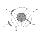
- FIG. 10 shows the piercing position of the straw 14 in such an experiment.
- the piercing positions of the straw 14 are positions a, b, c, and d indicated by hatching.
- the position a is a position near the center of the straw hole portion 20 and is shown as a circular figure concentric with the center of the straw hole portion 20.
- the position b is a position corresponding to the unhalf-cut portions UHc1 to UHc3 in FIG. 8, and the position c is out of the position a, but is a position in the straw hole portion 20.
- the position d is a position away from the straw hole portion 20. More specifically, the position d is separated from the arc-shaped half-cut portion C1 that defines the outermost shell of the straw hole portion 20 by 1.5 mm.
- the number of times the straw 14 was pierced into each of the positions a to d (N number), the strength necessary for the straw 14 to penetrate the lid 10 or the straw hole portion 20 (the straw piercing strength), the straw 14 Table 1 shows the number of times that the tip of the straw 14 has been bent (straw tip breakage).
- the straw piercing strength is the tensile and compression tester with the maximum stress until the straw penetrates through the straw piercing area at a speed of 100 mm / min (constant speed) with a straw of 4 mm in diameter with the container fixed. (Strograph) was used for measurement. Table 1
- the straw piercing strength of the conventional aluminum cap measured in the same experimental mode was approximately uniform over the entire region, and was 8.83N. Comparing the “straw piercing result” shown in Table 1 with the straw piercing strength of 8.83 N in the conventional aluminum cap, in the illustrated embodiment, in the straw hole portion 20 (in the arc-shaped half cut portions C1 to C3) If it is within the defined circle), it is clear that the straw 10 can penetrate the lid 10 with a straw piercing strength comparable to that of a conventional aluminum cap. In particular, in the vicinity of the center portion of the straw hole portion 20 (position a in FIG. 10), the straw 14 can be pierced with a weaker force than the conventional aluminum cap.
- the inventor also conducted an experiment on whether or not the synthetic resin material constituting the lid 10 falls into the container 12 when the lid 10 according to the illustrated embodiment is passed through the straw 14.
- the operation of penetrating the lid 10 with the straw 14 was repeated 50 times, but the synthetic resin material strip constituting the lid 10 did not fall into the container 12 (number of drops: 0/50).
- a similar experiment was performed on a conventional aluminum cap, but the result was similar to that of the illustrated embodiment.
- the container 12 filled with the beverage was closed with the lid 10 according to the illustrated embodiment, and in an upright state, the container 12 was dropped twice from a height of 50 cm onto the floor surface to confirm the presence or absence of breakage.
- Such an experiment was performed 50 times, but no damage was found (number of breakage: 0/50). From this, it was found that the lid 10 according to the illustrated embodiment has sufficient impact resistance.
- a similar experiment was performed on a conventional aluminum cap, but the result was similar to that of the illustrated embodiment.
- the lid 10 according to the illustrated embodiment has no risk of leakage of the beverage as the contents of the container 12 even when an impact is applied, and the force required to pierce the straw 14 is the conventional aluminum. It became clear that the material of the lid 10 was not mixed into the beverage when the straw 14 was pierced, similar to the cap.
Landscapes
- Engineering & Computer Science (AREA)
- Mechanical Engineering (AREA)
- Closures For Containers (AREA)
- Packages (AREA)
Abstract
Description
従来は、飲料或いは流体状の飲食物は、例えば、プラスチック製の容器にアルミキャップ(アルミニウム箔と樹脂との積層体)で蓋をしている場合が多かった。そのため、ストロー等を突き刺して、内容物(流体状の飲食物)をストローで吸引することが容易であった。
プラスチックの様な合成樹脂と、アルミキャップの様な不燃ゴミとは、分別して廃棄しなければならず、流体状の飲食物を飲んだ者は、容器(例えばプラスチック製)と、蓋(例えば、アルミニウム箔と樹脂との積層体)とを分離して、別々に、廃棄しなければならない。また、容器と蓋とでは、別々の日に集積所まで運搬して、回収して貰う必要があった。
その様に、容器と蓋とを分別して、別種類のゴミとして廃棄することは、ユーザーにとって、大きな負担となっている。
ここで、出願人の実験によれば、アルミキャップをプラスチック製のストローで突き刺す場合には、8.83Nの力で貫通することが出来る。これに対して、合成樹脂製の蓋をプラスチック製のストローで突き刺す場合には、27.20Nの力が必要である。
すなわち、蓋を合成樹脂で製造した場合には、内容物(流体上の飲食物)を飲むために、容器に添付されているプラスチック製のストローを突き刺して、蓋を貫通することが、従来のアルミキャップの場合に比較して、困難になるという問題が存在している。
ここで、容器の蓋が充足するべき性質としては、多少の衝撃が作用しても破損しないことが要求される。流通過程において、当該蓋をした容器が大量に運搬される段階で、衝撃が付加される場合があり、また、一般ユーザーが内容物を充填して蓋体が外される以前の状態の容器を落としてしまう場合が想定されるからである。
しかし、この技術(特許文献1)では、ストローを突き刺す部分の合成樹脂材料を薄くしているので、外部から衝撃が付加された場合に、当該薄くした部分が破損して、内容物が漏出してしまう恐れがある。
しかし、この技術においても、切り込み部における耐衝撃性が考慮されておらず、衝撃が付加された場合に切り込み部、特にその端部に応力集中が生じ、亀裂が進展してしまい、当該亀裂から内容物が漏出してしまう恐れが存在する。
また、蓋(10)における亀裂の進展を防止するためには、ストロー突き刺し用の領域(ストロー孔部分20)の代表寸法(例えば、円形のストロー孔部分20であれば、その直径)を所定値以下に抑えると共に、上記「ハーフカット加工」を施した箇所(ハーフカット部分)の長さも一定値以下にすることが有効であることを見出した。
ここで、切り込み部分(ハーフカットHc)の深さは合成樹脂材料の厚さの1/4~1/2(好ましくは約1/3)であり、ストロー突き刺し用の領域(20)の直径(R1×2)が8.0mm以下(好ましくは7.0mm以下)であり、切り込み部分(ハーフカットHc)の長さが3.0mm以下(好ましくは2.5mm以下)であるため、飲料用容器(12)に衝撃が作用した場合や、ストロー(14)で突き刺した場合でも、蓋(10)或いはストロー突き刺し用の領域(20)に亀裂が生じることや、切り込み部分(ハーフカットHc)から亀裂が進展してしまうことが防止される。そのため、飲料用容器(12)に衝撃が作用した場合に内容物である飲料が漏出してしまうことや、ストロー(14)で突き刺した場合にストロー(14)を突き刺した箇所以外から飲料が漏出してしまうことが防止される。
すなわち本発明によれば、衝撃が付加された場合等でも内容物が漏出することがなく、しかも、ストロー(14)により容易に突き刺すことが出来る様な合成樹脂(R)製の蓋(10)が提供されるのである。
また、前記仮想円の中心(未ハーフカット部分BCCの中心)から前記仮想円の半径方向外方へ延在する第2の直線状切り込み部分(ハーフカット部分TLC1~TLC3)を設ければ(請求項2)、三日月状の断面形状を有するストロー先端(14E)で蓋(10)を突き刺す際に、三日月状の断面形状を有するストロー先端(14E)を押圧する力が、厚さ寸法が薄い(概略1/4~1/2)第2の直線状切り込み部分(TLC1~TLC3)へ確実に作用する。そのため、ストロー(14)を突き刺す力による応力が集中し、第2の直線状切り込み部分(TLC1~TLC3)が容易且つ確実に破損する。
2・・・シール機
3・・・かしめ機構
4・・・レーザー加工装置
10・・・蓋
12・・・飲料用容器
14・・・ストロー
14E1、14E2、14E3、14EC・・・ストロー先端の断面
20・・・ストロー突き刺し用の領域/ストロー孔部分
Hc・・・切り込み部分/ハーフカット
R・・・合成樹脂材料
C1、C2、C3・・・ストロー孔部分の最外殻の円を定義する円弧状ハーフカット部分
TL1、TL2、TL3・・・ストロー孔部分に正三角形を定義する直線状ハーフカット部分
TLC1、TLC2、TLC3・・・ストロー孔部分の中心から半径方向外方へ延在する直線状ハーフカット部分
TLM1、TLM2、TLM3・・・ストロー孔部分に形成された直線状ハーフカット部分
C1B、C2B、C3B、TL1B、TL2B、TL3B、UHc1、UHc2、UHc3・・・ハーフカット部分が形成されていない領域/未ハーフカット部分
BCC・・・ストロー孔部分の中心
a、b、c、d・・・ストロー突き刺し位置
図1において、本発明の実施形態に係る蓋は全体が符号10で示されており、飲料用容器12の開口部(図1では容器12の上方端部)を覆っている。なお、蓋10は、アルミニウム箔を基材として含まない全体が合成樹脂のみで形成されている。例えば、PS(ポリスチレン)樹脂、AS(スチレン‐アクリロニトリル共重合体)樹脂、ABS(アクリロニトリル‐ブタジエン‐スチレン共重合体)系樹脂、AXS樹脂(アクリロニトリルとスチレン成分を有するターポリマー)等の合成樹脂の1種又は2種以上を基材とするものが挙げられる(特開2004-74796号公報、特開2004-76009号公報、特開2004-76010号公報参照)。
図1では、ストロー14を蓋10に突き刺そうとする状態が示されており、ストロー14の先端は、蓋10中央に設けたストロー突き刺し用の領域(ストロー孔部分)20に向かって移動している。
図2から明らかなように、ハーフカットHcは、合成樹脂材料Rを、その厚さ方向寸法tの約1/4~約1/2、好ましくは約1/3の深さDまで切り込んだ断面三角形の切欠部として、形成されている。そして、図示の実施形態では、厚さ195μmの合成樹脂材料Rに対して、ハーフカットHcの深さDは約60μm(蓋10の材料の厚さに対して約1/3)に設定されている。
図3において、飲料品容器内に所定の内容物が充填され且つ適正にシールされた製品を製造するためのラインは、全体を符号Lで示されており、飲料用容器12が搬送される搬送装置(例えば、ベルトコンベア)Cvが設けられている。
搬送装置Cvには、充填機1、シール機2、かしめ機構3、レーザー加工装置4が設けられている。
シール機2でシールされた段階では合成樹脂製の蓋材は、単に容器12の開口部を覆っているだけであるが、かしめ機構3において、蓋材の縁部10E(図1参照)が容器12の側面部の上縁部(開口側縁部)に沿う様に折り曲げられ、図1で示す様に容器12の開口部を包囲する様に被覆する。
充填機1、シール機2、かしめ機構3は、公知の機器を適用可能である。
レーザー加工装置4は、公知・市販のレーザー加工用装置(例えば、株式会社キーエンス製造、販売の3次元制御のCO2レーザーマーカー:商品名「ML-Z9500」)が使用可能である。
係るレーザー加工装置4により、飲料用容器12の開口部を包囲する様に被覆した合成樹脂製の蓋10の表面に、ハーフカットHcが形成される。
図4において、搬送装置Cv上に載置された飲料用容器12の開口部を被覆する蓋10に対して、レーザー加工装置4のレーザー照射部4LEからレーザー光線(例えばCO2レーザー光線)が照射されている。
図4において、搬送装置Cvは矢印ACで示す方向に移動し続けており、蓋10にハーフカットHcが形成される間も連続的に移動している。換言すれば、搬送装置Cvは矢印AC方向に連続移動しており、ハーフカットHcの形成時に停止している訳ではない。そして、レーザー加工装置4は、比較的高速で移動している物体(例えば、搬送装置Cv上の飲料用容器12の蓋10)に対して、所望の形状通りに正確にハーフカットHcを形成するだけの加工能力を具備している。
ここで、蓋10のストロー孔部分20において、ハーフカットHcが形成された個々の曲線部分や直線部分については、「ハーフカット部分」と表記する。そして、ハーフカットHcが形成されていない部分については、「未ハーフカット部分」と表記する。
ストロー孔部分20は、外縁部に円弧を構成する様に設けられた3箇所の曲線状ハーフカット部分C1、C2、C3(円弧状の切り込み部分)を有している。3箇所の曲線状ハーフカット部分C1、C2、C3はストロー孔部分20の最外殻の仮想円を定義する様に形成されている。
曲線状或いは円弧状のハーフカット部分C1は、ハーフカットを施されていない部分(未ハーフカット部分)C1Bにより、曲線状或いは円弧状の部分C11、C12に分離されている。同様に、円弧状のハーフカット部分C2は、未ハーフカット部分C2Bにより円弧状部分C21、C22に分離され、円弧状のハーフカット部分C3は、未ハーフカット部分C3Bにより円弧状部分C31、C32に分離されている。
換言すれば、直線状のハーフカット部分TL1、TL2、TL3は、正三角形の3つの頂点を省略した様な形状を構成する様に配置されている。そして、直線状のハーフカット部分TL1、TL2、TL3は、円弧状ハーフカット部分C1、C2、C3によって定義される仮想円の外側に頂点が位置する正三角形(仮想正三角形)を定義している。
図5では、図面が煩雑化することを防止するため、前記仮想正三角形の重心、前記仮想円の中心、或いは、未ハーフカット部分BBCの中心については、符号を付して図示することをしていない。ただし、未ハーフカット部分BBCは小さな領域であるため、本明細書においては、簡略化のために、前記仮想正三角形の重心或いは前記仮想円の中心を、符号BCCで表現する場合がある。
同様に、直線状のハーフカット部分TL2は、未ハーフカット部分TL2Bにより直線状の部分TL21、TL22に分離され、直線状のハーフカット部分TL3は、未ハーフカット部分TL3Bにより直線状の部分TL31、TL32に分離されている。
ハーフカット部分TLC1は、ハーフカット部分TL1、TL3が形成する角度の2等分線(仮想線)上に配置されている。
ハーフカット部分TLC2は、ハーフカット部分TL1、TL2が形成する角度の2等分線(仮想線)上に配置されている。
ハーフカット部分TLC3は、ハーフカット部分TL2、TL3が形成する角度の2等分線(仮想線)上に配置されている。
図5において、符号ETLC1はハーフカット部分TLC1の正三角形頂点側(C1~C3が構成する円の中心とは反対側)の端部であり、符号ETLC2はハーフカット部分TLC2の正三角形頂点側(C1~C3が構成する円の中心とは反対側)の端部であり、符号ETLC3はハーフカット部分TLC3の正三角形頂点側(C1~C3が構成する円の中心とは反対側)の端部である。
そして、3本の直線状のハーフカット部分TLC1、TLC2、TLC3は、円弧状のハーフカット部分C1~C3が構成する円の中心(或いは、ハーフカット部分TL1、TL2、TL3が構成する正三角形の重心)において、未ハーフカット部分BCCによって分離している。
換言すれば、円弧状のハーフカット部分C1~C3が構成する円の中心は、或いは、直線状のハーフカット部分TL1~TL3が構成する正三角形の重心は、未ハーフカット部分BCCとなっている。
より詳細には、直線状のハーフカット部分TLM1は、直線状のハーフカット部分TL1、TLC1、TLC2で構成される二等辺三角形状の領域内において、ハーフカット部分TL1と平行に形成されている。
直線状のハーフカット部分TLM2は、直線状のハーフカット部分TL2、TLC2、TLC3で構成される二等辺三角形状の領域内において、ハーフカット部分TL2と平行に形成されている。
直線状のハーフカット部分TLM3は、直線状のハーフカット部分TL3、TLC3、TLC1で構成される二等辺三角形状の領域内において、ハーフカット部分TL3と平行に形成されている。
図6において、円弧状の部分C11の曲率半径が符号R1で示されており、曲率半径R1は例えば3mmに設定されている。ここで、曲率半径R1は、円弧状のハーフカット部分C1、C2、C3で構成される円の曲率半径であり、円弧状のハーフカット部分C1、C2、C3及びその部分C11、C12、C21、C22、C31、C32で共通している。
円弧状のハーフカット部分C1~C3で構成される円の中心、或いは、直線状のハーフカット部分TLC1~TLC3で構成される正三角形の重心は、上述した様に、未ハーフカット部分BCCとなっているが、この未ハーフカット部分BCCの直径が符号φ1で示されており、例えば0.1mmである。換言すると、φ1(=0.1mm)は、3本のハーフカット部分TLC1~TLC3における前記円の中心側(前記正三角形の重心側)端部を結ぶ仮想円の直径である。
ここで、中心角とは、円弧状のハーフカット部分C1~C3で構成される円の中心(直線状のハーフカット部分TLC1~TLC3で構成される正三角形の重心と一致する)に対して為す角度を意味している。
円弧状ハーフカット部分C3における部分C31の中心角θ1と、部分C32の中心角θ2とは同一角度であり、例えば37.5°である。部分C31と部分C32とを分離する未ハーフカット部分C3Bの中心角θCBは、例えば5°である。ここで、中心角θCBは、直線状ハーフカット部分TL3における部分TL31とTL32とを分離する未ハーフカット部分TL3Bの中心角でもある。
図6で示す中心角θCB(=5°)は、部分C11とC12とを分離する未ハーフカット部分C1B、部分C21と部分C22とを分離する未ハーフカット部分C2B、部分TL11とTL12とを分離する未ハーフカット部分TL1B、部分TL21とTL22とを分離する未ハーフカット部分TL2Bの各々における中心角と同一である。
なお、図6で示す中心角θCB(=5°)は、未ハーフカット部分TL1B~TL3Bが少なくとも0.2mm以上となる様に設定されている。
直線状ハーフカット部分TL3の部分TL32の右端部と、直線状ハーフカット部分TL1の部分TL11の左端部とを結ぶ直線の長さ(弦の長さ)BHCとしては、例えば1mmに設定されている。
図5の円弧状のハーフカット部分C1~C3は、ストロー孔部分20の中心BCCから一定の範囲については、同一の力でストロー14が突き刺さり、蓋10を貫通できるようにするため、当該一定の範囲を円形領域として定義するため、当該円形領域の最外殻である円周を定義するために、設けられている。
換言すれば、三角形の重心を目視するよりも、円の中心を目視することの方が容易であり、ストロー14を突き刺すべき箇所に確実にストロー14を突き刺すことが出来るようにするため、ストロー孔部分20の最外殻を定義するハーフカット部分C1、C2、C3は、ストロー孔部分20の中心BCCと同一の曲率中心を有する円弧として形成したのである。
さらに、円弧状のハーフカット部分C1~C3を最外殻部分とすることにより、ストロー孔部分20の面積を、最外殻が三角形や四角形の場合に比較して、増加することが出来る。
ストロー14を蓋10に突き刺した部分の断面(ストロー14先端の断面)は、図7において符号14E1、14E2、14E3、14ECで示す様に、三日月状となる。図7から明らかな様に、係る三日月状の断面形状を有するストロー14先端は、ストロー孔部分20の中心から半径方向外方へ延在する直線状ハーフカット部分TLC1、TLC2、TLC3内の2個或いは3個の近傍に配置されることになる。従って、ストロー14を押圧する力が、ハーフカット部分TLC1~TLC3へ確実に作用するので、蓋10における未ハーフカット部分に比較して厚さ寸法が薄い(概略1/4~1/2)のハーフカット部分Hcに対して、当該押圧力による応力が集中し、ハーフカット部分TLC1~TLC3が破損する。
特に、ストロー孔部分20の中心BCCにストロー14を突き刺した場合には、ストロー先端14Eが直線状ハーフカット部分TLC1~TLC3を貫通するので、ストロー14を押圧する力に起因する応力が、ハーフカット部分TLC1~TLC3に集中し易くなり、ストロー14で蓋10を突き通すことが容易になる。
すなわち、ハーフカット部分TL1~TL3と直線状ハーフカット部分TLM1~TLM3とを設けることによって、ハーフカット部分の数を増加してストロー孔部分20で未ハーフカット部分が占める面積を少なくでき、ストロー孔部分20の全ての領域において、蓋10をストロー14で突き刺すのに必要な力を比較的低いレベルに留めることが出来る。
そして、「蓋10による密封状態が保持される」という条件を充足した上で、ストロー14で蓋10を貫通し易いという条件が要求される。
すなわち、ハーフカットHcの深さDが、蓋10を構成する合成樹脂材料の厚さ寸法の約1/2よりも深いと、ストロー14を突き刺す以前の段階で、何らかの拍子にハーフカットHcが裂けてしまい、容器12内に密封されている飲料が漏出してしまう恐れがある。
一方、ハーフカットHcの深さDが、蓋10を構成する合成樹脂材料の厚さ寸法の約1/4よりも浅いと、ストロー14で蓋10のストロー孔部分20を突き刺して貫通するのに、大きな力が必要となってしまう。
そのため、ハーフカットHcの深さDは、蓋10を構成する合成樹脂材料の厚さ寸法の約1/4~約1/2、好ましくは約1/3に設定されている。
係る空気孔を確保することにより、ストロー14を突き刺して飲料品を飲む際に、容器12の外部から容器12内へ空気が流れる通路が確保されるので、ストロー14周囲に係る空気通路が形成されることにより異音が生じる事態を防止することが出来る。
飲料用容器12については、複数の容器12を1パックに梱包して、梱包品を多数積層して運搬する場合がある。係る運搬に際して、積層状態の梱包品を載置する際に、容器12に対して衝撃が作用する可能性がある。また、個々のユーザーが購入後、飲料用容器12を落下してしまう場合においても、容器12に対して衝撃が作用する。
この様に容器12に衝撃が作用した場合において、ストロー孔部分20が簡単に破損して、内容物である飲料が漏出することがないように、ストロー孔部分20には、一定以上の耐衝撃性が要求される。
ハーフカット部分Hc間の距離(間隔)が少なくとも0.2mm以上となる様に設定されているのは、その様な耐衝撃性を確保するためである。すなわち、ハーフカット部分の間隔が0.2mm未満であると、衝撃が作用した際には、間隔が0.2mm未満の領域に応力が集中して、ハーフカット部分が連続し、そこから裂けてしまう恐れがある。
係る事態を防止するためにも、ハーフカット部分の間隔が、少なくとも0.2mm以上となる様に設定している。
当該現状の亀裂は、ストロー孔部分20の直径(=円弧状のハーフカット部分C1~C3の曲率半径×2)が大きい場合にも、発生してしまうことが、発明者による実験で判明した。
そして発明者による実験では、ストロー孔部分20に形成される個々のハーフカット部分の長さが3.0mm以下(好ましくは2.5mm以下)で、且つ、ストロー孔部分20の直径が8.0mm以下(好ましくは7.0mm以下)であれば、その様な亀裂が発生しないことが分かった。
係る実験結果に基づいて、ストロー孔部分20が設定されている。換言すれば、図6で示す曲率半径や中心角は、「ストロー孔部分20に形成される個々のハーフカット部分の長さが3.0mm以下(好ましくは2.5mm以下)で、且つ、ストロー孔部分20の直径が8.0mm以下(好ましくは7.0mm以下)」と言う条件を充足するように設定されている。
一方、蓋10全体を横断しない様な亀裂の発生については、個々のハーフカット部分の長さが大きく影響することが、発明者の実験で明らかになっている。
係る未ハーフカット部分は、図8において、点線で示す領域UHc1、UHc2、UHc3として、表現されている。
未ハーフカット部分UHc1、UHc2、UHc3を設けると、ストロー孔部分20をストロー14で突き刺した際に、ハーフカット部分Hcで合成樹脂が裂けて、図9で示す様に裂けてしまったハーフカット部分Hcで囲まれた領域DPが下方に垂れ下がったとしても、未ハーフカット部分UHc1、UHc2、UHc3が残存するため、領域DPは蓋10から分離することなく、蓋10に残存する。そのため、領域DPを構成する合成樹脂の細片(或いは切片)が、蓋10の下方に存在する飲料品に混入してしまうことが防止される。
先ず、図示の実施形態に係る蓋10について、ストロー14の突き刺し位置と、蓋10を貫通するのに必要な突き刺し強さとを計測した。
図10は、係る実験におけるストロー14の突き刺し位置を示している。図10において、ストロー14の突き刺し位置は、ハッチングを付して示す位置a、b、c、dである。
位置aは、ストロー孔部分20の中心近傍位置であり、ストロー孔部分20の中心と同心の円形図形として示されている。
位置bは、図8における未ハーフカット部分UHc1~UHc3に相当する位置であり、位置cは位置aから外れているが、ストロー孔部分20内の位置である。
位置dはストロー孔部分20から外れた位置である。より詳細には、位置dは、ストロー孔部分20の最外殻を定義する円弧状のハーフカット部分C1から1.5mm離隔している。
表1

表1で示す「ストロー突き刺し結果」を、従来のアルミキャップにおけるストロー突き刺し強さ8.83Nとを比較すれば、図示の実施形態では、ストロー孔部分20内(円弧状ハーフカット部分C1~C3で定義される円の内部)であれば、従来のアルミキャップと同程度のストロー突き刺し強さで、ストロー14で蓋10を貫通することが出来ることが明らかである。
特に、ストロー孔部分20の中心部近傍(図10の位置a)については、従来のアルミキャップよりも弱い力で、ストロー14を突き刺すことが出来る。
しかし、位置dの「ストロー先端折れ」を参照すれば明らかな様に、図示の実施形態では、ストロー孔部分20から1.5mm離隔した箇所(位置d)にストロー14を突き刺しても、ストロー14が折れ曲がることなく、全ての試行において蓋10を突き通すことが出来た。
すなわち、図示の実施形態によれば、ストロー14を突き刺し難い箇所にストロー14を突き刺しても、ストロー14の先端が折れ曲がることなく、蓋10を突き通すことが出来ることが判明した。
係る実験では、ストロー14により蓋10を貫通する動作を50回繰り返したが、蓋10を構成する合成樹脂材料の細片が容器12内に落下することはなかった(落下回数:0/50)。
従来のアルミキャップについても同様な実験を行なったが、図示の実施形態と同様な結果であった。
このことから、図示の実施形態に係る蓋10は、十分な耐衝撃性を備えていることが分かった。
従来のアルミキャップについても同様な実験を行なったが、図示の実施形態と同様な結果であった。
Claims (4)
- 全体が合成樹脂(R)で形成され、その一部に実質的に円形のストロー突き刺し用の領域(20)が設けられており、ストロー突き刺し用の領域(20)には合成樹脂材料の厚さの1/4~1/2の深さの切り込み部分(Hc)を複数形成し、ストロー突き刺し用の領域(20)の直径が8.0mm以下であり、切り込み部分(Hc)の長さが3.0mm以下であることを特徴とする飲料用容器の蓋。
- ストロー突き刺し用の領域(20)には、ストロー突き刺し用の領域(20)の最外殻の仮想円を定義する円弧状の切り込み部分(C1、C2、C3)と、円弧状の切り込み部分(C1、C2、C3)によって定義された仮想円の内側の領域に形成されて、頂点が前記仮想円の外側に位置し且つ重心が前記仮想円の中心と一致する様な仮想正三角形を定義する第1の直線状切り込み部分(TL1、TL2、TL3)と、前記仮想円の中心から前記仮想円の半径方向外方へ延在する第2の直線状切り込み部分(TLC1、TLC2、TLC3)と、第1の直線状切り込み部分(TL1、TL2、TL3)と第2の直線状切り込み部分(TLC1、TLC2、TLC3)との間の領域で第1の直線状切り込み部分(TL1、TL2、TL3)と平行に延在する第3の直線状切り込み部分(TLM1、TLM2、TLM3)が形成されている請求項1の飲料用容器の蓋。
- 第2の直線状切り込み部分(TLC1、TLC2、TLC3)を半径方向外方に延長した領域(UHc1、UHc2、UHc3)には、切り込み部分(Hc)が形成されていない請求項2の飲料用容器の蓋。
- 円弧状の切り込み部分(C1~C3)及び第1の直線状切り込み部分(TL1~TL3)は、切り込み部分が形成されていない領域(C1B、C2B、C3B、TL1B、TL2B、TL3B)によって分離されている請求項2、3の何れかの飲料用容器の蓋。
Priority Applications (7)
| Application Number | Priority Date | Filing Date | Title |
|---|---|---|---|
| KR1020117005327A KR101493402B1 (ko) | 2008-08-29 | 2009-08-18 | 음료용 용기의 뚜껑 |
| JP2010526661A JP5027306B2 (ja) | 2008-08-29 | 2009-08-18 | 飲料用容器の蓋 |
| US13/059,217 US8464888B2 (en) | 2008-08-29 | 2009-08-18 | Lid of beverage container |
| CN2009801349746A CN102164827B (zh) | 2008-08-29 | 2009-08-18 | 饮料容器的盖 |
| EP09809801.5A EP2332852B1 (en) | 2008-08-29 | 2009-08-18 | Lid of beverage container |
| HK11110980.8A HK1156588B (en) | 2008-08-29 | 2009-08-18 | Lid of beverage container |
| ES09809801.5T ES2496690T3 (es) | 2008-08-29 | 2009-08-18 | Tapa de envase de bebida |
Applications Claiming Priority (2)
| Application Number | Priority Date | Filing Date | Title |
|---|---|---|---|
| JP2008221340 | 2008-08-29 | ||
| JP2008-221340 | 2008-08-29 |
Publications (1)
| Publication Number | Publication Date |
|---|---|
| WO2010024148A1 true WO2010024148A1 (ja) | 2010-03-04 |
Family
ID=41721317
Family Applications (1)
| Application Number | Title | Priority Date | Filing Date |
|---|---|---|---|
| PCT/JP2009/064422 Ceased WO2010024148A1 (ja) | 2008-08-29 | 2009-08-18 | 飲料用容器の蓋 |
Country Status (8)
| Country | Link |
|---|---|
| US (1) | US8464888B2 (ja) |
| EP (1) | EP2332852B1 (ja) |
| JP (1) | JP5027306B2 (ja) |
| KR (1) | KR101493402B1 (ja) |
| CN (1) | CN102164827B (ja) |
| ES (1) | ES2496690T3 (ja) |
| TW (1) | TWI445647B (ja) |
| WO (1) | WO2010024148A1 (ja) |
Cited By (3)
| Publication number | Priority date | Publication date | Assignee | Title |
|---|---|---|---|---|
| JP2011255944A (ja) * | 2010-06-11 | 2011-12-22 | Nippon Dekishii:Kk | 飲料容器用蓋 |
| JP2014213923A (ja) * | 2013-04-30 | 2014-11-17 | 日本製紙株式会社 | 飲料用ノンアルミ紙容器 |
| WO2023224131A1 (ja) * | 2022-05-20 | 2023-11-23 | 株式会社Ky7 | 蓋体、蓋体付き容器、蓋体と容器の組み合わせ |
Families Citing this family (7)
| Publication number | Priority date | Publication date | Assignee | Title |
|---|---|---|---|---|
| US20140072674A1 (en) * | 2012-09-10 | 2014-03-13 | Nova Chemicals Inc. | Leak-proof containers, made from expandable thermoplastic resin beads |
| KR20160002199U (ko) * | 2014-12-17 | 2016-06-28 | 씨제이제일제당 (주) | 음료용기용 뚜껑 |
| US9543384B2 (en) * | 2015-02-26 | 2017-01-10 | SK Hynix Inc. | Semiconductor package |
| US9333668B1 (en) * | 2015-07-09 | 2016-05-10 | John W. Goddard | System and method for converting beverage containers with removable lids into spill-resistant sippy cups |
| CN205992121U (zh) * | 2016-04-25 | 2017-03-01 | 珠海艾派克科技股份有限公司 | 处理盒的显影仓 |
| US12600541B2 (en) * | 2021-03-08 | 2026-04-14 | Smoodi, Inc. | Blend through cup lid |
| US12195251B2 (en) * | 2023-02-27 | 2025-01-14 | David Andrews | Straw gripper and tab separator for disposable cup or lid and methods of use |
Citations (12)
| Publication number | Priority date | Publication date | Assignee | Title |
|---|---|---|---|---|
| US3524566A (en) * | 1968-08-12 | 1970-08-18 | American Can Co | Straw slot for container closure |
| JPS4849075A (ja) | 1971-10-20 | 1973-07-11 | ||
| US5147065A (en) * | 1991-11-04 | 1992-09-15 | James River Corporation Of Virginia | Disposable cup lid having a tear-resistant straw slot |
| JPH0761469A (ja) | 1993-08-19 | 1995-03-07 | Dainippon Printing Co Ltd | 蓋 材 |
| DE10057277A1 (de) * | 2000-11-17 | 2002-05-29 | Ferratec Werkzeug Und Formenba | Flaschenverschluß |
| JP2004076009A (ja) | 2002-07-31 | 2004-03-11 | Shikoku Kakoki Co Ltd | 冷間成形用ポリスチレン系樹脂シート |
| JP2004074796A (ja) | 2002-07-31 | 2004-03-11 | Shikoku Kakoki Co Ltd | 冷間成形加工品及びその製造方法 |
| JP2004076010A (ja) | 2002-07-31 | 2004-03-11 | Shikoku Kakoki Co Ltd | 冷間成形用樹脂組成物 |
| EP1486149A1 (en) * | 2003-06-09 | 2004-12-15 | The First Years Inc. | Drinking cup lid and straw |
| JP2005075443A (ja) * | 2003-09-03 | 2005-03-24 | Japan Crown Cork Co Ltd | ストロー差込口を有する合成樹脂製キャップ |
| JP2005343508A (ja) * | 2004-06-02 | 2005-12-15 | Shikoku Kakoki Co Ltd | 充填包装機械 |
| JP2006240667A (ja) * | 2005-03-03 | 2006-09-14 | Japan Crown Cork Co Ltd | ストロー刺し込み口付プラスチックキャップ |
Family Cites Families (12)
| Publication number | Priority date | Publication date | Assignee | Title |
|---|---|---|---|---|
| JPS4849075U (ja) | 1971-10-04 | 1973-06-27 | ||
| US3945528A (en) * | 1972-10-18 | 1976-03-23 | Maryland Cup Corporation | Apertured lid and method for manufacturing same |
| US4948009A (en) * | 1989-12-28 | 1990-08-14 | Takashi Sawatani | Straw-insertable lid for paper cup |
| US5314324A (en) * | 1990-11-30 | 1994-05-24 | Wendt Michael L | Apparatus for forming a partible port in a production piece |
| US5397023A (en) * | 1993-12-06 | 1995-03-14 | James River Corporation Of Virginia | Disposable cup lid having a tear-resistant straw through-slit |
| CN2210157Y (zh) * | 1994-09-13 | 1995-10-18 | 陈重 | 铝塑易拉盖 |
| DE19621676A1 (de) * | 1996-05-30 | 1997-12-11 | Zeller Plastik Koehn Graebner | Verschlußmembran |
| US6158155A (en) * | 1998-07-21 | 2000-12-12 | Boney; David Hunter | Lid for a beverage container |
| US20020145000A1 (en) * | 2001-04-10 | 2002-10-10 | Hongbiao Li | Non-spillable beverage container |
| US6783019B2 (en) * | 2001-09-14 | 2004-08-31 | Jeffrey J. Zettle | Container lid with selectable opening |
| CN101155535A (zh) * | 2005-02-17 | 2008-04-02 | 弗朗瑟达·詹姆斯·埃斯蒂斯·怀特 | 具有吸管的饮料容器或者容器盖 |
| US8196772B2 (en) * | 2009-04-17 | 2012-06-12 | Richard Joseph Leon | Disposable beverage cup with lid isolation system |
-
2009
- 2009-08-18 KR KR1020117005327A patent/KR101493402B1/ko active Active
- 2009-08-18 ES ES09809801.5T patent/ES2496690T3/es active Active
- 2009-08-18 CN CN2009801349746A patent/CN102164827B/zh active Active
- 2009-08-18 EP EP09809801.5A patent/EP2332852B1/en active Active
- 2009-08-18 JP JP2010526661A patent/JP5027306B2/ja active Active
- 2009-08-18 US US13/059,217 patent/US8464888B2/en active Active
- 2009-08-18 WO PCT/JP2009/064422 patent/WO2010024148A1/ja not_active Ceased
- 2009-08-28 TW TW098128946A patent/TWI445647B/zh active
Patent Citations (12)
| Publication number | Priority date | Publication date | Assignee | Title |
|---|---|---|---|---|
| US3524566A (en) * | 1968-08-12 | 1970-08-18 | American Can Co | Straw slot for container closure |
| JPS4849075A (ja) | 1971-10-20 | 1973-07-11 | ||
| US5147065A (en) * | 1991-11-04 | 1992-09-15 | James River Corporation Of Virginia | Disposable cup lid having a tear-resistant straw slot |
| JPH0761469A (ja) | 1993-08-19 | 1995-03-07 | Dainippon Printing Co Ltd | 蓋 材 |
| DE10057277A1 (de) * | 2000-11-17 | 2002-05-29 | Ferratec Werkzeug Und Formenba | Flaschenverschluß |
| JP2004076009A (ja) | 2002-07-31 | 2004-03-11 | Shikoku Kakoki Co Ltd | 冷間成形用ポリスチレン系樹脂シート |
| JP2004074796A (ja) | 2002-07-31 | 2004-03-11 | Shikoku Kakoki Co Ltd | 冷間成形加工品及びその製造方法 |
| JP2004076010A (ja) | 2002-07-31 | 2004-03-11 | Shikoku Kakoki Co Ltd | 冷間成形用樹脂組成物 |
| EP1486149A1 (en) * | 2003-06-09 | 2004-12-15 | The First Years Inc. | Drinking cup lid and straw |
| JP2005075443A (ja) * | 2003-09-03 | 2005-03-24 | Japan Crown Cork Co Ltd | ストロー差込口を有する合成樹脂製キャップ |
| JP2005343508A (ja) * | 2004-06-02 | 2005-12-15 | Shikoku Kakoki Co Ltd | 充填包装機械 |
| JP2006240667A (ja) * | 2005-03-03 | 2006-09-14 | Japan Crown Cork Co Ltd | ストロー刺し込み口付プラスチックキャップ |
Non-Patent Citations (1)
| Title |
|---|
| See also references of EP2332852A4 * |
Cited By (5)
| Publication number | Priority date | Publication date | Assignee | Title |
|---|---|---|---|---|
| JP2011255944A (ja) * | 2010-06-11 | 2011-12-22 | Nippon Dekishii:Kk | 飲料容器用蓋 |
| JP2014213923A (ja) * | 2013-04-30 | 2014-11-17 | 日本製紙株式会社 | 飲料用ノンアルミ紙容器 |
| WO2023224131A1 (ja) * | 2022-05-20 | 2023-11-23 | 株式会社Ky7 | 蓋体、蓋体付き容器、蓋体と容器の組み合わせ |
| JP2024055747A (ja) * | 2022-05-20 | 2024-04-18 | 株式会社Ky7 | 蓋体、蓋体付き容器、蓋体と容器の組み合わせ |
| JP7527549B2 (ja) | 2022-05-20 | 2024-08-05 | 株式会社Ky7 | 蓋体、蓋体付き容器、蓋体と容器の組み合わせ |
Also Published As
| Publication number | Publication date |
|---|---|
| US8464888B2 (en) | 2013-06-18 |
| JPWO2010024148A1 (ja) | 2012-01-26 |
| EP2332852A4 (en) | 2012-12-12 |
| ES2496690T3 (es) | 2014-09-19 |
| JP5027306B2 (ja) | 2012-09-19 |
| EP2332852B1 (en) | 2014-07-30 |
| CN102164827A (zh) | 2011-08-24 |
| CN102164827B (zh) | 2012-10-31 |
| TW201016559A (en) | 2010-05-01 |
| KR20110052693A (ko) | 2011-05-18 |
| HK1156588A1 (en) | 2012-06-15 |
| TWI445647B (zh) | 2014-07-21 |
| US20110204057A1 (en) | 2011-08-25 |
| EP2332852A1 (en) | 2011-06-15 |
| KR101493402B1 (ko) | 2015-02-16 |
Similar Documents
| Publication | Publication Date | Title |
|---|---|---|
| JP5027306B2 (ja) | 飲料用容器の蓋 | |
| US9309036B2 (en) | Package with enclosed utensil | |
| RU2698734C1 (ru) | Упаковка типа "пакет" и соответствующий способ модификации такой упаковки | |
| JP2010137902A (ja) | 飲料容器用蓋 | |
| WO2014045730A1 (ja) | 二室容器及び二液の混合方法 | |
| KR101758746B1 (ko) | 천공 가능성이 개선된 음료 컨테이너 | |
| NZ238741A (en) | Beverage container with straw piercable top access forming folding tab for venting | |
| KR20090012799U (ko) | 음료 용기용 캡 | |
| HK1156588B (en) | Lid of beverage container | |
| JP5278859B2 (ja) | 飲料用ストロー付飲料容器及び飲料用ストロー | |
| JPS582767Y2 (ja) | 容器用上蓋 | |
| CN108602582B (zh) | 待附接到包装的中空体和用于生产所述中空体的方法 | |
| JP5340063B2 (ja) | 液体食品用容器のストロー用開口装置 | |
| US7597918B2 (en) | Method of vacuum packaging pre-cooked whole lobsters and the packages made therewith | |
| JP2019218086A (ja) | 円錐型包装容器及び包装食品 | |
| JP2014061925A (ja) | 二室容器 | |
| EP2003063A1 (en) | Can structure | |
| JP2007176597A (ja) | 飲料用ストロー付飲料容器及び飲料用ストロー | |
| JP3199113U (ja) | 飲料用容器 | |
| JP2002253415A (ja) | 異物混入防止機能付き飲料吸入具 | |
| JP2016150748A (ja) | ストロー付き飲料容器 | |
| JP2006141575A (ja) | 飲料用ストロー | |
| HK1227365A1 (en) | Drinks container with improved piercing characteristic | |
| JP2014061926A (ja) | 二室容器 |
Legal Events
| Date | Code | Title | Description |
|---|---|---|---|
| WWE | Wipo information: entry into national phase |
Ref document number: 200980134974.6 Country of ref document: CN |
|
| 121 | Ep: the epo has been informed by wipo that ep was designated in this application |
Ref document number: 09809801 Country of ref document: EP Kind code of ref document: A1 |
|
| WWE | Wipo information: entry into national phase |
Ref document number: 2010526661 Country of ref document: JP |
|
| NENP | Non-entry into the national phase |
Ref country code: DE |
|
| ENP | Entry into the national phase |
Ref document number: 20117005327 Country of ref document: KR Kind code of ref document: A |
|
| WWE | Wipo information: entry into national phase |
Ref document number: 2009809801 Country of ref document: EP |
|
| WWE | Wipo information: entry into national phase |
Ref document number: 13059217 Country of ref document: US |