WO2010024294A1 - 溶接加工装置 - Google Patents
溶接加工装置 Download PDFInfo
- Publication number
- WO2010024294A1 WO2010024294A1 PCT/JP2009/064864 JP2009064864W WO2010024294A1 WO 2010024294 A1 WO2010024294 A1 WO 2010024294A1 JP 2009064864 W JP2009064864 W JP 2009064864W WO 2010024294 A1 WO2010024294 A1 WO 2010024294A1
- Authority
- WO
- WIPO (PCT)
- Prior art keywords
- welding
- station
- positioning
- blank
- blank material
- Prior art date
- Legal status (The legal status is an assumption and is not a legal conclusion. Google has not performed a legal analysis and makes no representation as to the accuracy of the status listed.)
- Ceased
Links
Images






Classifications
-
- B—PERFORMING OPERATIONS; TRANSPORTING
- B23—MACHINE TOOLS; METAL-WORKING NOT OTHERWISE PROVIDED FOR
- B23K—SOLDERING OR UNSOLDERING; WELDING; CLADDING OR PLATING BY SOLDERING OR WELDING; CUTTING BY APPLYING HEAT LOCALLY, e.g. FLAME CUTTING; WORKING BY LASER BEAM
- B23K37/00—Auxiliary devices or processes, not specially adapted for a procedure covered by only one of the other main groups of this subclass
- B23K37/04—Auxiliary devices or processes, not specially adapted for a procedure covered by only one of the other main groups of this subclass for holding or positioning work
- B23K37/047—Auxiliary devices or processes, not specially adapted for a procedure covered by only one of the other main groups of this subclass for holding or positioning work moving work to adjust its position between soldering, welding or cutting steps
-
- B—PERFORMING OPERATIONS; TRANSPORTING
- B23—MACHINE TOOLS; METAL-WORKING NOT OTHERWISE PROVIDED FOR
- B23K—SOLDERING OR UNSOLDERING; WELDING; CLADDING OR PLATING BY SOLDERING OR WELDING; CUTTING BY APPLYING HEAT LOCALLY, e.g. FLAME CUTTING; WORKING BY LASER BEAM
- B23K26/00—Working by laser beam, e.g. welding, cutting or boring
- B23K26/08—Devices involving relative movement between laser beam and workpiece
- B23K26/0869—Devices involving movement of the laser head in at least one axial direction
- B23K26/0876—Devices involving movement of the laser head in at least one axial direction in at least two axial directions
-
- B—PERFORMING OPERATIONS; TRANSPORTING
- B23—MACHINE TOOLS; METAL-WORKING NOT OTHERWISE PROVIDED FOR
- B23K—SOLDERING OR UNSOLDERING; WELDING; CLADDING OR PLATING BY SOLDERING OR WELDING; CUTTING BY APPLYING HEAT LOCALLY, e.g. FLAME CUTTING; WORKING BY LASER BEAM
- B23K26/00—Working by laser beam, e.g. welding, cutting or boring
- B23K26/20—Bonding
- B23K26/21—Bonding by welding
- B23K26/24—Seam welding
- B23K26/26—Seam welding of rectilinear seams
-
- B—PERFORMING OPERATIONS; TRANSPORTING
- B23—MACHINE TOOLS; METAL-WORKING NOT OTHERWISE PROVIDED FOR
- B23K—SOLDERING OR UNSOLDERING; WELDING; CLADDING OR PLATING BY SOLDERING OR WELDING; CUTTING BY APPLYING HEAT LOCALLY, e.g. FLAME CUTTING; WORKING BY LASER BEAM
- B23K37/00—Auxiliary devices or processes, not specially adapted for a procedure covered by only one of the other main groups of this subclass
- B23K37/04—Auxiliary devices or processes, not specially adapted for a procedure covered by only one of the other main groups of this subclass for holding or positioning work
- B23K37/0408—Auxiliary devices or processes, not specially adapted for a procedure covered by only one of the other main groups of this subclass for holding or positioning work for planar work
-
- B—PERFORMING OPERATIONS; TRANSPORTING
- B23—MACHINE TOOLS; METAL-WORKING NOT OTHERWISE PROVIDED FOR
- B23K—SOLDERING OR UNSOLDERING; WELDING; CLADDING OR PLATING BY SOLDERING OR WELDING; CUTTING BY APPLYING HEAT LOCALLY, e.g. FLAME CUTTING; WORKING BY LASER BEAM
- B23K2101/00—Articles made by soldering, welding or cutting
- B23K2101/18—Sheet panels
Definitions
- the present invention relates to a welding processing apparatus for welding a plurality of blank materials to each other.
- a plurality of welding stations are arranged in parallel with the transfer line, and welding is performed at one welding station while a jig pallet is carried at another welding station. Then, positioning is performed, and when welding at one welding station is completed, welding is performed at another welding station. According to this welding apparatus, the entire work time can be shortened.
- the present invention has been made in consideration of such circumstances, and an object of the present invention is to provide a welding processing apparatus that reduces the number of required welding stations and is advantageous in terms of space and cost.
- the present invention has been devised to achieve the above object.
- the welding processing apparatus according to claim 1 of the present invention is a welding processing apparatus that welds a plurality of blank materials against each other, a positioning station that positions the blank materials, and a welding head that welds the blank materials to each other.
- a first and second table movable between the positioning station and the welding station, and the plurality of blanks are fixed to predetermined positions of the first and second tables.
- a fixing device wherein the second table is moved to the welding station when the first table is moved to the positioning station, and the second table is moved when the first table is moved to the welding station. Is moved to the positioning station, and the plurality of blanks are moved to the positioning station.
- a welding apparatus is the welding apparatus according to claim 1, wherein a carry-in station on which a plurality of blank materials before welding are placed, a carry-out station on which the finished product is placed, and a blank material on the carry-in station On the first or second table in the positioning station, and on the first or second table moved to the positioning station after welding is completed in the welding station. And a second moving device for moving the finished product to the carry-out station.
- the welding processing apparatus includes a first positioning stage disposed on one side of the welding station and a second positioning stage disposed on the other side,
- the second table is moved to the welding station when the first table is moved to the first positioning stage, and the second table is moved to the second positioning stage when the first table is moved to the welding station. It is moved to.
- the welding processing apparatus according to the first aspect, wherein the positioning station is disposed on one side of the welding station, and the first table and the second table are moved along movement paths having different heights. It is characterized by that.
- the first and second tables include a positioning device for positioning the plurality of blank materials.
- the welding processing apparatus causes the blank to abut against the stopper that can protrude at a predetermined position on the first and second tables.
- a pressing member that presses the blank material as much as possible.
- the welding apparatus according to claim 7 is the welding apparatus according to claim 5, wherein the plurality of blank materials include at least a first blank material and a second blank material, and the first blank material is disposed at a position predetermined by the positioning device. Then, the first blank material is fixed to one of the first and second tables by the fixing device, and the second blank material is pressed against the first blank material to abut the second blank material. A material is fixed to the other of the first and second tables by the fixing device.
- the welding apparatus is the welding apparatus according to claim 7, wherein one of the first and second tables further includes a guide member, and the first blank member is fixed to the one table by the fixing device device.
- the guide member is located in the vicinity of both sides of the side of the first blank material to which the second blank material is to be abutted, and prevents the second blank material from running over the first blank material. It is characterized by.
- the fixing device includes a suction unit that sucks lower surfaces of the plurality of blank materials.
- the welding apparatus according to claim 10 is characterized in that, in claim 9, the adsorption unit is a magnetic type mounted on the table.
- the welding processing apparatus of Claim 1 of this invention has the 1st and 2nd table to which a blank material is fixed, These 1st and 2nd tables move between a positioning station and a welding station. . Then, when the operation of welding the blank material fixed on one table is performed at the welding station, the operation of positioning and fixing the blank material on the other table is performed at the positioning station. Therefore, since welding and positioning of a blank material can be performed simultaneously, the whole operation time can be shortened. In addition, as long as the same welding is performed on the blank material, only one welding station is required, which is a significant advantage in terms of space compared to the above-described conventional apparatus.
- the welding processing apparatus when one of the first and second tables is in the welding station, a blanking work on the table is performed. Meanwhile, the other of the first and second tables is in the positioning station, and the second moving device moves the finished product on the first or second table moved to the positioning station to the unloading station, The first moving device moves the blank material of the carry-in station onto the first or second table in the positioning station. Therefore, the work time can be shortened as a whole, including carrying in blank materials and carrying out finished products.
- the second table when the first table is moved to the first positioning stage, the second table is moved to the welding station. Then, when the first table is moved to the welding station, the second table is moved to the second positioning stage. Moreover, the first positioning stage and the second positioning stage are arranged on the opposite sides with the welding station interposed therebetween. For this reason, both stations can be arranged in a plane, and thereby the height of the apparatus can be kept small.
- the welding processing apparatus wherein the positioning station is disposed only on one side of the welding station, and the first table and the second table move between the positioning station and the welding station, respectively, at different heights. Thereby, the size of the whole apparatus in planar view can be made compact.
- the blank material is positioned at a predetermined position on the first or second table by a positioning device provided on the table.
- a stopper is protruded at a predetermined position on the first or second table, and the blank is pressed by the pressing member so that the blank contacts the stopper, and positioning is performed. Is executed.
- a 1st blank material is fixed to a table with a fixing device.
- the second blank is fixed to the table by the fixing device in a state where the second blank is pressed against the first blank. Thereby, both blank materials are positioned and fixed on the table. Therefore, the second blank material can be accurately positioned with respect to the first blank material.
- the second blank material is a first blank when the second blank material is abutted against the first blank material. Even if it tries to ride on the upper side of the material, such riding is reliably prevented by the guide provided on the table.
- the fixing device since the fixing device includes an adsorption unit that adsorbs the lower surface of each blank material, a clamp or the like does not protrude from the upper surface of the blank material. Thereby, there is no restriction
- the adsorption unit is a magnetic type mounted on each table, the lower surface of the blank material can be easily switched between adsorption and non-adsorption.
- FIG. 10 is an enlarged view of the welding station and positioning station of FIG. 9. It is a right view of FIG. It is a block diagram explaining the movement control of a 1st or 2nd table.
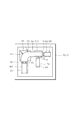
- the present welding processing apparatus includes a welding station 2, a first positioning stage 4 disposed on one side of the welding station 2, and a second positioning stage 6 disposed on the other side. It has.
- the first positioning stage 4 and the second positioning stage 6 form a positioning station.
- a rail 8 is provided across the welding station 2 and the positioning station (the first positioning stage 4 and the second positioning stage 6).
- the first table 10 and the second table 12 move on the rail 8. That is, the first table 10 can move between the first positioning stage 4 and the welding station 2 along the rail 8. Further, the second table 12 can move between the welding station 2 and the second positioning stage 6 along the rail 8.
- the welding station 2 is provided with a welding device 14 for welding the blank material B.
- Each table 10 and 12 has a function of positioning and fixing the blank B on the table. These functions will be described later.
- a carry-in station 16 for carrying in the blank material B is arranged, and on the other side, a carry-out station 18 for carrying out the finished product C after welding of the blank material B is arranged.
- robots 20 and 22 are arranged as first moving devices for moving the blank material B on the carry-in station 16 to the positioning stages 4 and 6, respectively.
- the robot 24 as a second moving device moves the finished product C, which has been welded with the blank B on the positioning stages 4 and 6, to the unloading station 18.
- And 26 are respectively arranged.
- Each of the robots 20, 24, 26, and 28 has suction portions 20a, 22a, 24a, and 26a that suck the blank material B at their tips.
- the carry-in station 16 is provided with a turntable 30 whose upper surface is divided into two and can be rotated around a shaft 28.
- the carry-out station 18 is provided with a turntable 34 that has an upper surface divided into two and can rotate around a shaft 32.
- the blank material B is placed on the turntable 30 at a predetermined position on the left half of the turntable 30 shown in the drawing.
- a predetermined number of blank materials B are stacked and placed.
- the turntable 30 rotates 180 ° about the shaft 32. Therefore, the placed blank B moves to the right half of the turntable 30 shown in the figure. Therefore, the left half of the turntable 30 is empty.
- the next predetermined number of blank materials B are immediately placed.
- the blank B placed on the right half of the turntable 30 shown in the figure is further moved to the positioning station and the right half of the turntable 30 becomes empty, the turntable 30 rotates again. For this reason, the blank material B is always kept in the right half of the turntable.
- the robot 20 sucks the blank material B in the right half of the turntable 30 shown in the figure by the suction part 20a and places it on the first table 10.
- the blank material B is positioned and fixed at a predetermined position, and then the first table 10 moves to the welding station 2.
- the second table 12 moves to the second positioning stage 6 as indicated by a two-dot chain line 12a in FIG.
- the robot 22 sucks the blank material in the right half of the turntable 30 shown in the figure by the suction part 22a and places it on the second table 12 in the second positioning stage 6.
- the first table 10 on which the finished product C is placed moves to the first positioning stage 4 again.
- the second table on which the blank material B is placed moves to the welding station 2.
- the robot 24 sucks the finished product C on the first table 10 by the suction part 24a and moves it to the left half of the turntable 34 shown in the drawing.
- a predetermined number of finished products C are stacked on the left half of the turntable 34 shown in the figure.
- the turntable 34 rotates 180 ° about the shaft 32.
- the finished product C moves to the right half of the turntable 34 shown in the figure and is carried out by an operator or another robot.
- the robot 20 sucks the blank B in the right half of the turntable 30 by the sucking part 20a and moves it onto the first table 10. Then, in the first table 10, an operation is performed in which the blank material B is positioned and fixed at a predetermined position.
- the welding station 2 an operation of welding the blank materials B on the second table 12 to each other is performed by the welding device 14.
- the first table 10 moves to the welding station 2 and the second table 12 moves to the second positioning stage 6.
- the robot 26 sucks the finished product C on the second table 12 by the suction portion 26a, and moves to the left half of the turntable 34 shown in the drawing. Further, the robot 22 sucks the blank B in the right half of the turntable 30 by the sucking part 22a and moves it onto the second table 12. Then, in the first table 10, an operation is performed in which the blank material B is positioned and fixed at a predetermined position.
- the welding station 2 an operation of welding the blank materials B on the first table 10 to each other is performed by the welding device 14.
- the first and second tables 8 and 12, the robots 20, 22, 24, and 26 and the turntables 20 and 34 are repeatedly operated as described above.
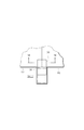
- the welding device 14 in the welding station 2 is demonstrated with reference to FIG.2 and FIG.3.
- the welding device 14 is bridged between two rails 14a extending parallel to the rail 8 on both sides of the welding station 2, two posts 14b respectively guided by the rails 14a, and the two posts 14b.
- a rail 14c extending perpendicular to the rail 14a, a slider 14d guided by the rail 14c, and a welding head 14f supported by the slider 14d via a support member 14e are provided.
- the position of the post 14b relative to the rail 14a and the position of the slider 14d relative to the rail 14c are controlled by a controller (not shown) according to the welding position.
- the blank material B is composed of four members B1, B2, B3, and B4, and each butted portion is welded.
- the welding head 14f is moved to each butted portion that needs to be welded. Can be moved along.
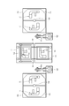
- a positioning device and a fixing device for the blank material B provided in each of the tables 10 and 12 will be described with reference to FIGS. 4 and 5.
- Each table 10 and 12 is provided as a positioning device so as to be able to move in and out at a predetermined position, and is provided with a stopper pin that contacts the blank material B and a pressing member that presses the blank material in a predetermined direction.
- clamping devices magnet clamps (adsorption units) M1, M11, M2, M3, and M4 that are attached to the positions corresponding to the positioned blank material B on the tables 10 and 12 and adsorb the lower surface of the blank material B are provided. Is provided. Since these magnet clamps are magnetic, the lower surface of the blank material B can be easily switched between adsorption and non-adsorption.
- the blank material B1 is first positioned and then the tables 10, 12 Then, the blank materials B2, B3, B4 are positioned and fixed to the tables 10, 12.
- the six stopper pins S1 are projected to predetermined positions on the tables 10 and 12 in order to position the blank B1.
- the blank member B1 is pressed by the two pressing members P1 in the direction of the arrow shown in the drawing so as to be surely brought into contact with the stopper pin S1, thereby completing the positioning of the blank member B1.
- the blank material B1 is attracted by the magnet clamps M1 and M11, and thereby the blank material B1 is fixed at a predetermined position on the tables 10 and 12.
- each stopper pin S1 and the pressing member P1 are lowered into the tables 10 and 11 so as not to protrude onto the tables 10 and 11.
- the four stopper pins S ⁇ b> 2, the four stopper pins S ⁇ b> 3 and the four stopper pins S ⁇ b> 4 project on the tables 10 and 11 in order to position the blanks B ⁇ b> 1, B ⁇ b> 2 and B ⁇ b> 3.
- each blank material B2, B3, and B4 is reliably contact
- the stopper pins S2, S3, and S4 described above have a slight gap between the blank members B2, B3, and B4, and the blank members B2, B3, and B4 are respectively pressed members P2, P3. And when it is pressed by the member P4, it bears a guide function to prevent it from falling down.
- the positioning device described above has an apparatus for preventing one blank from riding on the other blank when each blank B2, B3 and B4 is pressed against the blank B1. Yes.
- the apparatus provided in relation to the blank materials B1 and B2 will be described.
- guide members 36 are provided on both sides of the butted portion of the blank material B1 and the blank material B2 in the tables 10 and 12.
- the guide member 36 has a groove 36a.
- the side portion of the butted portion between the blank members B1 and B2 is positioned so as to be accommodated in the groove 36a.
- channel 36a is set so that it can block, for example, even if the blank material B2 tries to run over the blank material B1. That is, the height of the groove 36a is set lower than the thickness when the blank material B1 and the blank material B2 are overlapped.
- the guide member 36 is retracted to a position where it does not overlap with the blanks B1 and B2 and is not projected to the tables 10 and 12 as disclosed by a two-dot chain line 38 in FIG. , Descend into the tables 10 and 11.
- the first and second tables 10 and 12 to which the blank material B is fixed are alternately arranged in the order of the first and second positioning stages 4 and 6 and the welding station 2. Moving. And the operation
- the positioning stage 4 or 6 performs an operation for positioning and fixing the blank material B on the other table 10 or 12. Therefore, since the blank material B can be welded and positioned at the same time, the entire operation time can be shortened. Moreover, as long as the same welding is performed on the blank material B, one welding station 2 is sufficient. For this reason, it is much more advantageous in terms of space than the above-described conventional apparatus.
- the first positioning stage 4 and the second positioning stage 6 are arranged on the opposite sides with respect to the welding station 2, both the stages 4 and 6 can be arranged together with the welding station 2 in a plane. Thus, the height of the apparatus can be kept small.
- the welding work of the blank material B on the table is performed.
- the other of the first and second tables 10 and 12 is located in the positioning station 4 or 6.
- the robot 24 or 26 moves the finished product C on the table 10 or 12 moved to the positioning stage 4 or 6 onto the turntable 34 of the carry-out station 18.
- the robot 20 or 22 moves the blank B on the turntable 30 at the carry-in station 16 onto the table 10 or 6 at the positioning station 4 or 6. Therefore, the working time can be shortened as a whole, including carrying in the blank material B and carrying out the finished product C.
- the first blank material B1 is positioned using the stopper S1 and the pressing member P1. And it fixes to the predetermined position on the tables 10 and 12 using the magnet clamps M1 and M11. Further, the second to fourth blank materials B2 to B4 are pressed by the pressing members P2 to P4, respectively, and abutted against the first blank material B1. In this state, the blank materials B2 to B4 are fixed to the tables 10 and 12 by magnet clamps M2 to M4, respectively. Therefore, the second to fourth blank materials B2 to B4 can be accurately positioned with respect to the first blank material B1.
- the lower surfaces of the blank materials B1 to B4 are attracted by the magnet clamps M1, M11 and M2 to M4.
- the blank materials B1 to B4 are fixed to the tables 10 and 11, clamps or the like do not protrude from the upper surfaces of the blank materials B1 to B4. Therefore, there is no restriction on the plane movement of the welding head 14f of the welding apparatus 14 that performs laser welding in the welding station 2, and the welding head 14F can be moved at high speed.
- the welding processing apparatus includes a welding station 42 and a positioning station 44 disposed on one side of the welding station 2.
- the first table 50 is slidable along the lower rail 46.
- the second table 52 is slidable along the upper rail 48. That is, the first table 50 can move between the positioning station 44 and the welding station 42 along the lower rail 46. Further, the second table 52 can move between the positioning station 44 and the welding station 42 along the upper rail 48.
- the welding station 42 is provided with a welding device 54 for welding the blank material B.
- the first and second tables 50 and 52 have a function of positioning and fixing the blank material B on the table.
- a loading station 56 for loading the blank material B is arranged.
- an unloading station 58 for unloading the finished product that has been welded with the blank B is disposed.
- a robot 60 is arranged as a first moving device that moves the blank B on the carry-in station 56 to the positioning station 44.
- a robot 62 is disposed between the carry-out station 58 and the positioning station 44.
- the robot 62 is a second moving device that moves the finished product C on which the blank material B has been welded on the positioning station 44 to the unloading station 58.
- Each of the robots 60 and 62 has suction portions 60a and 62a that suck the blank material B at their tips.
- the carry-in station 56 is provided with a turntable 64 whose upper surface is divided into two and can be rotated around a shaft 64.
- the carry-out station 58 is provided with a turntable 70 that has an upper surface divided into two and can rotate around a shaft 68.
- the operations of the first and second tables 50 and 52, the robots 60 and 62, and the turntables 66 and 70 will be described in association with each other.
- the blank material B is placed on the turntable 66 at a predetermined position on the left half of the turntable 66 shown in the drawing.
- the blank material B is placed in a state where a predetermined number of layers are stacked. In this state, the turntable 66 rotates 180 ° about the shaft 64. Then, the placed blank material B moves to the right half of the turntable 66 shown in the figure of the turntable 66. At this time, since the left half of the turntable 66 is empty, the next predetermined number of blank materials B are immediately placed. When the right half of the turntable 66 shown in the figure becomes empty, the turntable 66 rotates again. As a result, the blank B is always placed on the right half of the turntable 66 shown in the drawing.
- the robot 60 sucks the blank material B in the right half of the turntable 66 shown in the drawing by the sucking unit 60 a and places it on the first table 50.
- the blank B is positioned and fixed at a predetermined position, and then the first table 50 moves along the lower rail 46 to the welding station 42.
- the second table 52 moves along the upper rail 48 to the positioning station 44.
- the robot 60 sucks the blank B in the right half of the turntable 66 shown in the figure by the sucking part 60a and places it on the second table 52 in the positioning station 44.
- the first table 50 on which the finished product C is placed moves again to the positioning station 44 along the lower rail 46.
- the second table 52 on which the blank material B is placed moves along the upper rail 48 to the welding station 42.
- the robot 62 sucks the finished product C on the first table 50 by the sucking part 62a and moves it to the left half of the turntable 70 shown in the drawing.
- the turntable 70 rotates.
- the finished product C moved to the right half of the turntable 70 shown in the figure is carried out by an operator or another robot.
- the robot 60 sucks the blank material B on the right half of the turntable 66 by the suction part 60 a and moves it onto the first table 50.
- the blank material B is positioned and fixed at a predetermined position.
- the welding station 42 an operation of welding the blank materials B on the second table 52 to each other is performed by the welding device 54.
- the first table 50 moves to the welding station 42 along the lower rail 46
- the second table 52 moves to the positioning station 44 along the upper rail. .
- the robot 62 sucks the finished product C on the second table 52 by the suction part 62a and moves it to the left half of the turntable 70 shown in the drawing. Further, the robot 60 sucks the blank B in the right half of the turntable 66 by the sucking part 60 a and moves it onto the second table 52. In the first table 50, the blank material B is positioned and fixed at a predetermined position.
- the welding station 42 an operation of welding the blank materials B on the first table 10 to each other is performed by the welding device 54.
- the first and second tables 50 and 52, the robots 60 and 62, and the turntables 66 and 70 repeat the above operations.
- the welding apparatus 54 in the welding station 42 is demonstrated with reference to FIG.10 and FIG.11.
- the welding device 54 is bridged between two rails 54a extending in parallel with the rail 8 on both sides of the welding station 2, two posts 54b guided respectively by the rails 54a, and the two posts 54b.
- a rail 54c extending perpendicularly to the rail 54a and vertically movable along the post 54b, a slider 54d guided by the rail 54c, and a welding head 54f supported by the slider 54d via a support member 54e are provided.
- the position of the post 54b with respect to the rail 14a, the position of the rail 54c with respect to the post 54b, and the position of the slider 54d with respect to the rail 54c are controlled by a controller (not shown) according to the welding position.
- the blank material B is composed of four members B1, B2, B3, and B4, and each butt portion is welded.
- the welding head 54f is placed on each butt portion that needs to be welded. Can be moved along.
- the first table 50 and the second table 52 are at different heights, but the welding head 54f can also move up and down, so that necessary welding operations can be performed.
- the first table 50 and the second table 52 have a positioning device and a fixing device for the blank material B, respectively, but the structure and operation thereof are the first table 10 and the second table in the first embodiment described above. The same ones as those provided on the table 12 are provided.
- the first and second tables 50 and 52 to which the blank material B is fixed are alternately arranged between the positioning station 44 and the welding station 42. Moving. Then, in the welding station 42, when the operation of welding the blank material B fixed on one table 50 or 52 is being performed, the positioning station 44 positions the blank material B on the other table 50 or 52. Fixing work is performed.
- the blank material B can be welded and positioned at the same time, so that the entire operation time can be shortened.
- only one welding station 42 is required, which is significantly advantageous in terms of space compared to the conventional apparatus.
- the first table 50 and the second table 52 move at different heights, one positioning station 44 is sufficient, and the entire apparatus in plan view can be made more compact than the welding processing apparatus of the first embodiment. Can do.
- one of the first and second tables 50 and 52 is in the welding station 42, and the welding work of the blank material B on the table is performed. Meanwhile, the other of the first and second tables 50 and 52 is in the positioning station 44, and the robot 62 transfers the finished product C on the table 50 or 52 moved to the positioning station 4 or 6 to the turntable 70 of the unloading station 58. Move up. Further, the robot 60 moves the blank B on the turntable 66 of the carry-in station 56 onto the table 50 or 52 in the positioning station 44. Therefore, as in the case of the first embodiment, the work time can be shortened as a whole, including carrying in the blank material B and carrying out the finished product C. In addition, since this welding processing apparatus has few positioning stations compared with 1st Embodiment, since the operating area required of the robot which moves the blank material B or the finished product C is small, reducing the number of robots. Can do.
- the welding device 14 or 54 is configured such that the welding head 14f or 54f is moved along the rail 14a or 54a extending in parallel with the rail 8 or 48.
- the table 10, 12 or 50, 52 on which the blank to be welded is placed can be moved along the rail 8 or 48.
- a block body that presses the butted portion of the blank material from above can be provided on the tables 10 and 12.
- FIG. 12 is a block diagram for explaining the movement control of the first or second table.
- the tables 10 and 12 (50 and 52) are connected to the drive source 100.
- the tables 10 and 12 slide and move on the rails 8 (46 and 48) described above.
- the movement timing, speed, and the like are controlled by a control unit 102 connected to the drive source 100.
- the tables 10 and 12 can be manually slid as necessary.
Landscapes
- Physics & Mathematics (AREA)
- Optics & Photonics (AREA)
- Engineering & Computer Science (AREA)
- Mechanical Engineering (AREA)
- Plasma & Fusion (AREA)
- Laser Beam Processing (AREA)
Abstract
Description
このような溶接を行う溶接加工装置において、レーザ溶接そのものは比較的短時間で完了することができる。これに比べて、ブランク材の搬入や位置決めは、時間がかかる。このため、ブランク材の搬入、位置決め、レーザ溶接、及び搬出までの工程を、同一場所にて行うと、全体としての作業時間は、一番時間のかかる工程に引きずられて長くなる。
請求項2の溶接加工装置は、請求項1において、溶接前の複数のブランク材が載置される搬入ステーションと、前記完成品が載置されるべき搬出ステーションと、前記搬入ステーション上のブランク材を、前記位置決めステーションにある前記第1または第2テーブルの上に移動する第1移動装置と、前記溶接ステーションで溶接が完了した後に、前記位置決めステーションに移動した前記第1テーブルまたは第2テーブル上の完成品を、前記搬出ステーションに移動する第2移動装置とを更に備えたことを特徴とする。
請求項5の溶接加工装置は、請求項1において、前記第1及び第2テーブルが、前記複数のブランク材を位置決めする位置決めデバイスを備えていることを特徴とする。
請求項7の溶接加工装置は、請求項5において、前記複数のブランク材が少なくとも第1ブランク材と第2ブランク材を含み、前記第1ブランク材を前記位置決めデバイスにより予め定められた位置に配置し、次いで前記第1ブランク材を前記固定デバイスにより前記第1及び第2テーブルの一方に固定し、さらに前記第1ブランク材に第2ブランク材を突き合わせるべく押圧させた状態で前記第2ブランク材を前記固定デバイスにより前記第1及び第2テーブルの他方に固定させることを特徴とする。
請求項9の溶接加工装置は、請求項1において、前記固定デバイスが、前記複数のブランク材の下面をそれぞれ吸着する吸着ユニットを備えていることを特徴とする。
請求項5の溶接加工装置において、前記ブランク材は、前記テーブルに備えられた位置決めデバイスにより、第1又は第2テーブル上の定められた位置に位置決めされる。
請求項7の溶接加工装置において、第1ブランク材を前記位置決めデバイスより位置決めする。次に、第1ブランク材を固定デバイスによりテーブルに固定する。次に、第1ブランク材に第2ブランク材を突き合わせるべく押圧させた状態で第2ブランクを固定デバイスによりテーブルに固定する。これにより、両ブランク材がテーブル上に位置決めされ、かつ固定される。したがって、第1ブランク材に対して第2ブランク材を精度良く位置決めすることができる。
請求項9の溶接加工装置において、固定デバイスが、各ブランク材の下面を吸着する吸着ユニットを備えているので、ブランク材の上面にクランプ等が突出しない。これにより、レーザ溶接を行う前記溶接ヘッドの移動に制約がなく、同溶接ヘッドの高速移動が可能となる。
本溶接加工装置は、図1に開示されるように、溶接ステーション2と、この溶接ステーション2の一側に配置された第1位置決めステージ4と、他側に配置された第2位置決めステージ6とを備えている。この第1位置決めステージ4と、第2位置決めステージ6で、位置決めステーションを形成している。これらの溶接ステーション2及び位置決めステーション(第1位置決めステージ4、第2位置決めステージ6)に亘ってレール8が設けられている。第1テーブル10と第2テーブル12は、このレール8上を移動する。すなわち、第1テーブル10は、レール8に沿って第1位置決めステージ4と溶接ステーション2とを移動可能である。また、第2テーブル12は、レール8に沿って溶接ステーション2と第2位置決めステージ6とを移動可能である。溶接ステーション2には、ブランク材Bを溶接する溶接装置14が設けられている。各テーブル10及び12は、ブランク材Bをテーブル上に位置決めし、かつ固定する機能を有している。これらの機能については後述する。
ここで、第1及び第2テーブル10及び12と、各ロボット20,22,24,26と、各ターンテーブル30及び34の作動を互いに関連付けて説明する。
溶接ステーション2における溶接作業が完了し、かつ第2位置決めステージ6におけるブランク材Bの載置が完了すると、完成品Cを載せた第1テーブル10が再び第1位置決めステージ4に移動する。同時に、ブランク材Bを載せた第2テーブルが溶接ステーション2に移動する。
そして、第1位置決めステージ4及び溶接ステーション2での作業が完了すると、第1テーブル10は溶接ステーション2に移動し、第2テーブル12は第2位置決めステージ6に移動する。
第1及び第2テーブル8及び12と、各ロボット20,22,24,26と、各ターンテーブル20及び34は、以上のような作動を繰り返し行うものである。
次に、溶接ステーション2における溶接デバイス14を、図2及び図3を参照して説明する。
次に、各テーブル10及び12にそれぞれ設けられているブランク材Bの位置決めデバイス及び固定デバイスを図4及び図5を参照して説明する。
そして、この溶接加工装置においては、まずブランク材B1を位置決めした上でテーブル10,12に固定し、次いでブランク材B2、B3,B4を位置決めしてテーブル10,12に固定する。
上述の位置決めデバイスは、各ブランク材B2,B3及びB4をブランク材B1に当接するように押圧したときに、一方のブランク材が他方のブランク材に乗り上げることを防止するための装置を有している。ここでは、ブランク材B1とB2と関係において設けられた装置を説明する。
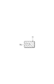
この実施形態に係る溶接加工装置は、溶接ステーション42と、同溶接ステーション2の一側に配置された位置決めステーション44とを備えている。第1テーブル50は下部レール46に沿ってスライド可能である。第2テーブル52は上部レール48に沿ってスライド可能である。すなわち、第1テーブル50は、下部レール46に沿って位置決めステーション44と溶接ステーション42とを移動可能である。また、第2テーブル52は、上部レール48に沿って位置決めステーション44と溶接ステーション42とを移動可能である。溶接ステーション42には、ブランク材Bを溶接する溶接装置54が設けられている。第1及び第2テーブル50及び52は、ブランク材Bをテーブル上に位置決めし、かつ固定する機能を有している。
ここで、第1及び第2テーブル50及び52と、各ロボット60及び62と、各ターンテーブル66及び70の動作を互いに関連付けて説明する。
溶接ステーション42における溶接作業が完了し、かつ位置決めステーション44におけるブランク材Bの載置が完了すると、完成品Cを載せた第1テーブル50が再び下部レール46に沿って位置決めステーション44に移動する。同時に、ブランク材Bを載せた第2テーブル52が上部レール48に沿って溶接ステーション42に移動する。
そして、位置決めステーション44及び溶接ステーション42での作業が完了すると、第1テーブル50は下部レール46に沿って溶接ステーション42に移動し、第2テーブル52は上部レールに沿って位置決めステーション44に移動する。
第1及び第2テーブル50及び52と、各ロボット60及び62と、各ターンテーブル66及び70は、以上のような作動を繰り返し行うものである。
次に、溶接ステーション42における溶接装置54を、図10及び図11を参照して説明する。
以上より明らかなように、この第2の実施形態に係る溶接加工装置において、ブランク材Bが固定される第1及び第2のテーブル50及び52は、位置決めステーション44と溶接ステーション42とを交互に移動する。そして溶接ステーション42において、一方のテーブル50または52上に固定されたブランク材Bを溶接する作業が行われているときに、位置決めステーション44において他方のテーブル50または52上にブランク材Bを位置決め・固定する作業が行われる。したがって、第1実施形態の場合と同様に、ブランク材Bの溶接と位置決めを同時に行うことができるので、全体の作業時間を短縮できる。しかも、ブランク材Bに対して同じ溶接を行う限り、溶接ステーション42は1つで足りるので、従来装置に比べてスペース的に格段に有利である。しかも、第1テーブル50と第2テーブル52が異なる高さを移動するので、1つの位置決めステーション44で足り、第1の実施形態の溶接加工装置よりも、平面視における装置全体をコンパクトにすることができる。
以上で、本発明の実施形態の説明を終えるが、本発明は上述した実施形態に限定されるものではない。
上述した各実施形態において、溶接装置14または54は、いずれも溶接ヘッド14fまたは54fが、レール8または48と平行に延びたレール14aまたは54aに沿って移動されるように構成されているが、代わりに溶接ステーション2または42において、溶接されるブランク材が載置されたテーブル
10,12または50,52を、レール8または48に沿って移動させるようにすることも可能である。ガイド部材36に関しても、例えばブランク材の突き合わせ部分を上方から押さえ込むようなブロック体をテーブル10,12に設けることが可能である。
図示したように、テーブル10,12(50,52)は、駆動源100と接続されている。この駆動源100が駆動することで、テーブル10,12は上述したレール8(46,48)をスライドして移動する。この移動タイミングや速度等は、駆動源100と接続された制御部102にて制御されている。なお、テーブル10,12は必要に応じて手動でスライドさせることも可能である。
4 第1位置決めステージ
6 第2位置決めステージ
8 第1テーブル
10 第2テーブル
14 溶接装置
16 搬入ステーション
18 搬出ステーション
42 溶接ステーション
44 位置決めステーション
50 第1テーブル
52 第2テーブル
54 溶接装置
56 搬入ステーション
58 搬出ステーション
Claims (10)
- 複数のブランク材を互いに突き合わせて溶接する溶接加工装置であって、
前記ブランク材の位置決めを行う位置決めステーションと、
前記ブランク材を相互に溶接する溶接ヘッドを有する溶接ステーションと、
前記位置決めステーションと前記溶接ステーションとの間で移動可能な第1及び第2テーブルと、
前記複数のブランク材を前記第1及び第2テーブルの予め定められた位置に固定する固定デバイスとを備え、
前記第1テーブルが前記位置決めステーションに移動されたときに前記第2テーブルが前記溶接ステーションに移動され、前記第1テーブルが前記溶接ステーションに移動されたときに前記第2テーブルが前記位置決めステーションに移動され、
前記複数のブランク材が、前記位置決めステーションにおいて前記第1テーブルまたは第2のテーブルに固定された後、前記第1のテーブルまたは第2テーブルと共に前記溶接ステーションに移動され、前記溶接ヘッドにより互いに溶接されて完成品が得られることを特徴とする溶接加工装置。 - 溶接前の複数のブランク材が載置される搬入ステーションと、
前記完成品が載置されるべき搬出ステーションと、
前記搬入ステーション上のブランク材を、前記位置決めステーションにある前記第1または第2テーブルの上に移動する第1移動装置と、
前記溶接ステーションで溶接が完了した後に、前記位置決めステーションに移動した前記第1テーブルまたは第2テーブル上の完成品を、前記搬出ステーションに移動する第2移動装置とを更に備えたことを特徴とする請求項1記載の溶接加工装置。 - 上記位置決めステーションは、上記溶接ステーションの一側に配置された第1位置決めステージと他側に配置された第2位置決めステージとを有し、
前記第1テーブルが第1位置決めステージに移動されたときに前記第2テーブルが前記溶接ステーションに移動され、前記第1テーブルが前記溶接ステーションに移動されたときに前記第2テーブルが前記第2位置決めステージに移動されることを特徴とする請求項1記載の溶接加工装置。 - 前記位置決めステーションが、前記溶接ステーションの一側に配置され、
前記第1テーブルと第2テーブルが互いに異なる高さの移動経路に沿って移動されることを特徴とする請求項1記載の溶接加工装置。 - 前記第1及び第2テーブルが、前記複数のブランク材を位置決めする位置決めデバイスを備えていることを特徴とする請求項1記載の溶接加工装置。
- 前記位置決めデバイスが、前記第1及び第2テーブル上の予め定められた位置にて突出可能なストッパと、前記ストッパに前記ブランクを当接させるべく同ブランク材を押圧する押圧部材とを有することを特徴とする請求項5記載の溶接加工装置。
- 前記複数のブランク材が少なくとも第1ブランク材と第2ブランク材を含み、
前記第1ブランク材を前記位置決めデバイスにより予め定められた位置に配置し、次いで前記第1ブランク材を前記固定デバイスにより前記第1及び第2テーブルの一方に固定し、さらに前記第1ブランク材に第2ブランク材を突き合わせるべく押圧させた状態で前記第2ブランク材を前記固定デバイスにより前記第1及び第2テーブルの他方に固定させることを特徴とする請求項5記載の溶接加工装置。 - 前記第1及び第2テーブルの一方がガイド部材を更に備え、前記第1ブランク材が前記固定デバイス装置により前記一方のテーブルに固定されたとき、前記ガイド部材は前記第2ブランク材が突き合わされるべき前記第1ブランク材の辺の両側部近傍に位置し、前記第2ブランク材が前記第1ブランク材の上方に乗り上げることを防止することを特徴とする請求項7記載の溶接加工装置。
- 前記固定デバイスが、前記複数のブランク材の下面をそれぞれ吸着する吸着ユニットを備えていることを特徴とする請求項1記載の溶接加工装置。
- 前記吸着ユニットが、前記テーブルに装着された磁気式であることを特徴とする請求項9記載の溶接加工装置。
Priority Applications (4)
| Application Number | Priority Date | Filing Date | Title |
|---|---|---|---|
| CN200980142380XA CN102196882A (zh) | 2008-08-28 | 2009-08-26 | 焊接加工装置 |
| RU2011111428/02A RU2479399C2 (ru) | 2008-08-28 | 2009-08-26 | Сварочное оборудование |
| EP09809945A EP2335864A4 (en) | 2008-08-28 | 2009-08-26 | WELDING DEVICE |
| US13/060,953 US20110147436A1 (en) | 2008-08-28 | 2009-08-26 | Welding equipment |
Applications Claiming Priority (2)
| Application Number | Priority Date | Filing Date | Title |
|---|---|---|---|
| JP2008219712A JP5212632B2 (ja) | 2008-08-28 | 2008-08-28 | 溶接加工装置 |
| JP2008-219712 | 2008-08-28 |
Publications (1)
| Publication Number | Publication Date |
|---|---|
| WO2010024294A1 true WO2010024294A1 (ja) | 2010-03-04 |
Family
ID=41721461
Family Applications (1)
| Application Number | Title | Priority Date | Filing Date |
|---|---|---|---|
| PCT/JP2009/064864 Ceased WO2010024294A1 (ja) | 2008-08-28 | 2009-08-26 | 溶接加工装置 |
Country Status (6)
| Country | Link |
|---|---|
| US (1) | US20110147436A1 (ja) |
| EP (1) | EP2335864A4 (ja) |
| JP (1) | JP5212632B2 (ja) |
| CN (1) | CN102196882A (ja) |
| RU (1) | RU2479399C2 (ja) |
| WO (1) | WO2010024294A1 (ja) |
Families Citing this family (10)
| Publication number | Priority date | Publication date | Assignee | Title |
|---|---|---|---|---|
| DE102009049892B3 (de) * | 2009-10-20 | 2011-01-05 | Emag Holding Gmbh | Vorrichtung zum Verbinden eines Werkstückes mit einem Fügeteil mittels Laserstrahlung |
| JP5645595B2 (ja) * | 2010-10-25 | 2014-12-24 | 株式会社アマダ | レーザ加工装置及びレーザ加工方法 |
| US8434657B2 (en) | 2011-06-09 | 2013-05-07 | Landoll Corporation | Gantry-based welding system and method |
| US8210418B1 (en) * | 2011-06-09 | 2012-07-03 | Landoll Corporation | Multi-station, gantry-based automated welding system |
| CN103600170B (zh) | 2013-04-28 | 2015-08-26 | 宝山钢铁股份有限公司 | 一种纵向金属板上下料与切割方法及其系统 |
| CN105364315A (zh) * | 2014-08-19 | 2016-03-02 | 深圳市普尔信通讯设备有限公司 | 一种自动镭射机 |
| CN105292988A (zh) * | 2015-11-26 | 2016-02-03 | 重庆贝华科技有限公司 | 一种空调外机焊接生产系统 |
| CN107283108B (zh) * | 2017-07-22 | 2019-01-11 | 合肥亚美科技股份有限公司 | 一种高空作业平台底盘搭焊模 |
| CN113732607B (zh) * | 2021-09-28 | 2023-10-10 | 九江职院船舶与海洋工程技术有限公司 | 一种船舶厚板焊接固定夹持装置 |
| CN218016641U (zh) * | 2022-03-30 | 2022-12-13 | 无锡先导智能装备股份有限公司 | 焊接装置 |
Citations (3)
| Publication number | Priority date | Publication date | Assignee | Title |
|---|---|---|---|---|
| JPH1177361A (ja) * | 1997-08-29 | 1999-03-23 | Nippei Toyama Corp | レーザ加工方法及びレーザ加工装置 |
| JPH11170080A (ja) * | 1997-12-08 | 1999-06-29 | Amada Co Ltd | レーザ加工機 |
| JP2000079513A (ja) * | 1998-09-03 | 2000-03-21 | Omron Corp | 自動加工装置 |
Family Cites Families (9)
| Publication number | Priority date | Publication date | Assignee | Title |
|---|---|---|---|---|
| SU751546A1 (ru) * | 1977-10-24 | 1980-07-30 | Предприятие П/Я Г-4365 | Поточна лини дл сборки и сварки металлических изделий |
| IT1249917B (it) * | 1991-06-14 | 1995-03-30 | Prima Ind Spa | Unita' per il taglio e/o la saldatura laser. |
| FR2698575B1 (fr) * | 1992-11-30 | 1995-03-17 | Lorraine Laminage | Dispositif de positionnement de flans de tôle dans une installation de soudage bord à bord en continu de ces flans de tôle. |
| US5630269A (en) * | 1995-06-19 | 1997-05-20 | General Motors Corporation | Method for fixturing abutted sheet metal parts for welding |
| JP4445633B2 (ja) * | 2000-02-28 | 2010-04-07 | 菊池プレス工業株式会社 | シーム溶接方法及びその装置 |
| RU2221683C1 (ru) * | 2002-09-16 | 2004-01-20 | Открытое акционерное общество "ГАЗ" | Робототехнический комплекс для сварки подсборок кузова автомобиля |
| FR2869558B1 (fr) * | 2004-04-29 | 2006-09-01 | Vai Clecim Soc Par Actions Sim | Procede de reglage de l'epaisseur du cordon de soudure de deux toles metalliques |
| CN101208175B (zh) * | 2005-06-06 | 2010-05-12 | 株式会社Ihi | 对接熔接板材的定位方法及装置 |
| US8113415B2 (en) * | 2007-06-07 | 2012-02-14 | Doben Limited | Modular welding fixture |
-
2008
- 2008-08-28 JP JP2008219712A patent/JP5212632B2/ja not_active Expired - Fee Related
-
2009
- 2009-08-26 CN CN200980142380XA patent/CN102196882A/zh active Pending
- 2009-08-26 US US13/060,953 patent/US20110147436A1/en not_active Abandoned
- 2009-08-26 WO PCT/JP2009/064864 patent/WO2010024294A1/ja not_active Ceased
- 2009-08-26 RU RU2011111428/02A patent/RU2479399C2/ru not_active IP Right Cessation
- 2009-08-26 EP EP09809945A patent/EP2335864A4/en not_active Withdrawn
Patent Citations (3)
| Publication number | Priority date | Publication date | Assignee | Title |
|---|---|---|---|---|
| JPH1177361A (ja) * | 1997-08-29 | 1999-03-23 | Nippei Toyama Corp | レーザ加工方法及びレーザ加工装置 |
| JPH11170080A (ja) * | 1997-12-08 | 1999-06-29 | Amada Co Ltd | レーザ加工機 |
| JP2000079513A (ja) * | 1998-09-03 | 2000-03-21 | Omron Corp | 自動加工装置 |
Non-Patent Citations (1)
| Title |
|---|
| See also references of EP2335864A4 * |
Also Published As
| Publication number | Publication date |
|---|---|
| EP2335864A1 (en) | 2011-06-22 |
| JP5212632B2 (ja) | 2013-06-19 |
| CN102196882A (zh) | 2011-09-21 |
| JP2010052008A (ja) | 2010-03-11 |
| RU2011111428A (ru) | 2012-10-10 |
| US20110147436A1 (en) | 2011-06-23 |
| EP2335864A4 (en) | 2012-07-04 |
| RU2479399C2 (ru) | 2013-04-20 |
Similar Documents
| Publication | Publication Date | Title |
|---|---|---|
| JP5212632B2 (ja) | 溶接加工装置 | |
| JP5196169B2 (ja) | ワークの加工装置 | |
| CN102307702A (zh) | 焊接加工装置及使用其的焊接加工方法 | |
| JP3074930B2 (ja) | 2種類以上を製造可能な溶接パネル製造装置 | |
| JPH04220184A (ja) | レザー光線溶接装置によって形成された少なくとも1つの溶接シームで少なくとも2つの薄板を結合する装置 | |
| CN102655979A (zh) | 工件定位装置和方法以及对焊用工件定位装置 | |
| JP3995865B2 (ja) | ワーク搬送装置 | |
| JP5196170B2 (ja) | 溶接加工装置及び溶接加工方法 | |
| JP2017170551A (ja) | 全自動ドリル装置 | |
| JP5077576B2 (ja) | 加工装置 | |
| JP3364464B2 (ja) | 自動加工装置 | |
| KR20000052622A (ko) | 열판 용착 방법 및 열판 용착 장치 | |
| JP2007319874A (ja) | ワーク位置決め装置 | |
| JP3558988B2 (ja) | 溶接方法及び溶接システム | |
| JP5152498B2 (ja) | ワークの位置決め装置及び方法並びに突合せ溶接用ワークの位置決め装置 | |
| JP2007160375A (ja) | レーザ加工機のワーク搬送装置 | |
| JP5778792B2 (ja) | 加工システム及び制御方法 | |
| JP4923752B2 (ja) | 板材加工搬送システム | |
| JP5196173B2 (ja) | 溶接加工装置 | |
| KR102857543B1 (ko) | 사일로용 샌드위치패널 용접 지그 및 이를 이용한 샌드위치패널 제조 장치 | |
| JP2007040831A (ja) | 回路基板保持装置 | |
| JPH10244378A (ja) | シーム溶接装置のハンドリング治具 | |
| JP4412961B2 (ja) | 溶接システム及び溶接方法 | |
| JP4458013B2 (ja) | ワーク位置決め方法および装置 | |
| JP2920992B2 (ja) | 溶接装置 |
Legal Events
| Date | Code | Title | Description |
|---|---|---|---|
| WWE | Wipo information: entry into national phase |
Ref document number: 200980142380.X Country of ref document: CN |
|
| 121 | Ep: the epo has been informed by wipo that ep was designated in this application |
Ref document number: 09809945 Country of ref document: EP Kind code of ref document: A1 |
|
| WWE | Wipo information: entry into national phase |
Ref document number: 1301/DELNP/2011 Country of ref document: IN Ref document number: 2009809945 Country of ref document: EP |
|
| WWE | Wipo information: entry into national phase |
Ref document number: 13060953 Country of ref document: US |
|
| NENP | Non-entry into the national phase |
Ref country code: DE |
|
| WWE | Wipo information: entry into national phase |
Ref document number: 2011111428 Country of ref document: RU |