WO2010024452A1 - 太陽電池の検査装置 - Google Patents
太陽電池の検査装置 Download PDFInfo
- Publication number
- WO2010024452A1 WO2010024452A1 PCT/JP2009/065281 JP2009065281W WO2010024452A1 WO 2010024452 A1 WO2010024452 A1 WO 2010024452A1 JP 2009065281 W JP2009065281 W JP 2009065281W WO 2010024452 A1 WO2010024452 A1 WO 2010024452A1
- Authority
- WO
- WIPO (PCT)
- Prior art keywords
- solar cell
- cameras
- camera
- dark room
- inspection apparatus
- Prior art date
- Legal status (The legal status is an assumption and is not a legal conclusion. Google has not performed a legal analysis and makes no representation as to the accuracy of the status listed.)
- Ceased
Links
Images


Classifications
-
- G—PHYSICS
- G01—MEASURING; TESTING
- G01N—INVESTIGATING OR ANALYSING MATERIALS BY DETERMINING THEIR CHEMICAL OR PHYSICAL PROPERTIES
- G01N21/00—Investigating or analysing materials by the use of optical means, i.e. using sub-millimetre waves, infrared, visible or ultraviolet light
- G01N21/84—Systems specially adapted for particular applications
- G01N21/88—Investigating the presence of flaws or contamination
- G01N21/95—Investigating the presence of flaws or contamination characterised by the material or shape of the object to be examined
- G01N21/9501—Semiconductor wafers
-
- G—PHYSICS
- G01—MEASURING; TESTING
- G01J—MEASUREMENT OF INTENSITY, VELOCITY, SPECTRAL CONTENT, POLARISATION, PHASE OR PULSE CHARACTERISTICS OF INFRARED, VISIBLE OR ULTRAVIOLET LIGHT; COLORIMETRY; RADIATION PYROMETRY
- G01J1/00—Photometry, e.g. photographic exposure meter
- G01J1/42—Photometry, e.g. photographic exposure meter using electric radiation detectors
- G01J1/4204—Photometry, e.g. photographic exposure meter using electric radiation detectors with determination of ambient light
-
- G—PHYSICS
- G01—MEASURING; TESTING
- G01R—MEASURING ELECTRIC VARIABLES; MEASURING MAGNETIC VARIABLES
- G01R31/00—Arrangements for testing electric properties; Arrangements for locating electric faults; Arrangements for electrical testing characterised by what is being tested not provided for elsewhere
- G01R31/40—Testing power supplies
-
- H—ELECTRICITY
- H02—GENERATION; CONVERSION OR DISTRIBUTION OF ELECTRIC POWER
- H02S—GENERATION OF ELECTRIC POWER BY CONVERSION OF INFRARED RADIATION, VISIBLE LIGHT OR ULTRAVIOLET LIGHT, e.g. USING PHOTOVOLTAIC [PV] MODULES
- H02S50/00—Monitoring or testing of PV systems, e.g. load balancing or fault identification
- H02S50/10—Testing of PV devices, e.g. of PV modules or single PV cells
-
- G—PHYSICS
- G01—MEASURING; TESTING
- G01R—MEASURING ELECTRIC VARIABLES; MEASURING MAGNETIC VARIABLES
- G01R31/00—Arrangements for testing electric properties; Arrangements for locating electric faults; Arrangements for electrical testing characterised by what is being tested not provided for elsewhere
- G01R31/28—Testing of electronic circuits, e.g. by signal tracer
- G01R31/302—Contactless testing
- G01R31/308—Contactless testing using non-ionising electromagnetic radiation, e.g. optical radiation
-
- Y—GENERAL TAGGING OF NEW TECHNOLOGICAL DEVELOPMENTS; GENERAL TAGGING OF CROSS-SECTIONAL TECHNOLOGIES SPANNING OVER SEVERAL SECTIONS OF THE IPC; TECHNICAL SUBJECTS COVERED BY FORMER USPC CROSS-REFERENCE ART COLLECTIONS [XRACs] AND DIGESTS
- Y02—TECHNOLOGIES OR APPLICATIONS FOR MITIGATION OR ADAPTATION AGAINST CLIMATE CHANGE
- Y02E—REDUCTION OF GREENHOUSE GAS [GHG] EMISSIONS, RELATED TO ENERGY GENERATION, TRANSMISSION OR DISTRIBUTION
- Y02E10/00—Energy generation through renewable energy sources
- Y02E10/50—Photovoltaic [PV] energy
Definitions
- the present invention relates to an apparatus for inspecting general performance of solar cells, such as solar cells, a string in which solar cells are connected in a row, and a solar cell panel in which a plurality of strings are arranged in parallel.
- a silicon type solar cell As a method of utilizing solar energy, a silicon type solar cell is known. In the production of solar cells, it is important to evaluate the performance of whether the solar cells have the desired power generation capability. In performance evaluation, output characteristics are usually measured. The output characteristic is performed as a photoelectric conversion characteristic for measuring the current-voltage characteristic of the solar cell under light irradiation. As the light source, sunlight is desirable, but a solar simulator is used because the intensity changes depending on the weather. In the solar simulator, a xenon lamp or a metal halide lamp is used instead of sunlight. Further, when these light sources are turned on for a long time, the light amount changes due to a temperature rise or the like.
- Patent Document 2 proposes a method of generating electroluminescence (EL) by applying a voltage in the forward direction to a polycrystalline silicon solar cell element. The same thing occurs with thin film solar cells. By observing the EL emitted from the solar cell element, the current density distribution can be understood, and the defect of the solar cell element can be known from the non-uniform current density distribution.
- EL electroluminescence
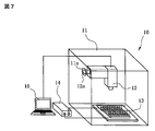
- FIG. 7 is a diagram schematically showing the configuration of the inspection apparatus described in Patent Document 2.
- the inspection apparatus 10 includes a dark room 11, a CCD camera 12 provided above the dark room 11, a power supply 14 for supplying a current to the solar cells 13 placed on the floor of the dark room 11, And an image processing device 15 for processing an image signal.
- the dark room 11 has a window 11a.
- a finder 12a of the CCD camera 12 is provided here, and a photographed image of the CCD camera 12 can be confirmed by looking into it with the naked eye.
- a personal computer is used as the image processing device 15. JP2007-88419 WO / 2006/059615
- the inspection apparatus 10 shown in FIG. 7 places the solar battery cell 13 underneath and takes a picture with a camera from above.
- the EL emitted from the solar battery cell 13 has a wavelength of 1,000 nm to 1,300 nm. It is faint light and can only be detected in the dark room 11. If the object to be measured is a single solar battery cell, the dark room 11 may be small because it is about 100 mm square. However, when it becomes a solar cell panel, it becomes a size of about 2 m ⁇ 1 m, and the dark room 11 needs to be large enough to accommodate it.
- the solar cell panel to be measured cannot be photographed by the CCD camera 12 unless it is placed in the dark room, a door that allows the solar cell panel to be taken in and out must be provided in the dark room.
- the inspection apparatus is configured to be carried into such a dark room, it is necessary to ensure light shielding when the installed door is closed.
- Such a structure is complicated and expensive.
- the present invention has been made in view of such circumstances, and is an inspection apparatus that causes EL light to flow by applying a forward current to a solar cell, has a simple structure, and has a good resolution of a captured image. It is an object of the present invention to provide a solar cell inspection apparatus capable of shortening the inspection time for defect inspection.
- a solar cell inspection apparatus includes a dark room having an opening on an upper surface, and a solar cell that is provided on the upper surface of the dark room and serves as an object to be measured. And a plurality of cameras provided in the dark room for photographing the object to be measured, and each camera photographs the entire portion of the solar cell by photographing the portion in charge of the solar cell. It is characterized by doing.
- a moving unit that moves the plurality of cameras is provided in the darkroom, or the moving unit includes a support member that fixes the plurality of cameras, and the support member is linearly advanced and retracted.
- each of the plurality of cameras is provided with a reflecting plate that photographs the portion in charge.
- the moving means may be configured to move the reflector together with the camera. Furthermore, it is good also as a structure which provides the rocking
- each of the plurality of cameras may be provided with a reflecting plate that captures the portion in charge and a swinging unit that swings the reflecting plate. Further, the opening may be closed with a transparent plate.
- a solar cell to be measured is supported on an opening on the upper surface of a dark room.
- each solar battery cell constituting the solar battery emits EL light.
- This light emission state is photographed by a plurality of cameras and analyzed by an image processing apparatus connected to the cameras, thereby determining the presence or absence of a solar cell defect.
- the solar cell can be inspected by placing it on the upper surface of the dark room from outside the dark room, and there is no need to provide a door for taking in and out the solar cell as the object to be measured. Therefore, the dark room can be reduced in size and the structure can be simplified.
- the moving means has a support member for fixing the plurality of cameras, and by moving the support member linearly, the plurality of cameras can be simultaneously moved in the same direction at the same speed.
- One can be manufactured at low cost.
- a production line manufactured apparatus such as a laminating apparatus
- the solar cell panel can be mounted on the inspection apparatus without being inverted by providing the inspection apparatus of the present invention with the opening provided on the upper surface of the dark room.
- the inspection apparatus of the present invention with the opening provided on the upper surface of the dark room.
- the dark room can be further reduced in size.
- FIG. 1 is a diagram showing a solar cell inspection apparatus according to the present invention, in which (a) is a plan view, (b) is a front view of (a), and (c) is a right side view.
- 2A and 2B are diagrams showing the configuration of the camera and the moving means of the solar cell inspection apparatus.
- FIG. 2A is a plan view
- FIG. 2B is a cross-sectional view taken along the line A-A in FIG. BB right sectional drawing
- (d) is a figure which shows the part in charge of each camera in the case of image
- FIGS. 3A and 3B are diagrams showing an embodiment of the present invention in which the dark room can be further reduced in size.
- FIG. 3A is a plan view
- FIG. 3B is a cross-sectional view taken along the line C-C in FIG. It is DD right sectional drawing of a).
- 4A and 4B are diagrams showing an embodiment in which the camera is swung as a moving means of the camera.
- FIG. 4A is a plan view
- FIG. 4B is a cross-sectional view taken along line EE in FIG. ) Is a right sectional view taken along line FF
- FIG. 4D is a diagram showing a portion in charge of each camera when the object to be measured is photographed.
- FIGS. 5A and 5B are diagrams showing an embodiment in which only the reflecting plate is swung.
- FIG. 5A is a plan view
- FIG. 5A is a plan view
- FIG. 5A is a plan view
- FIG. 5A is a plan view
- FIG. 5A is a plan view
- FIG. 5A is a plan view
- FIG. 5A is
- FIG. 5B is a sectional view taken along line GG in FIG. It is H right sectional drawing.
- 6A and 6B are explanatory views of the configuration of the solar cell measured by the inspection apparatus of the present invention, wherein FIG. 6A is a plan view and FIG. 6B is a cross-sectional view.
- FIG. 7 is a diagram schematically showing a configuration of a conventional solar cell inspection apparatus.
- FIG. 6 is an explanatory diagram of the configuration of the solar cell measured by the inspection apparatus of the present invention, (a) is a plan view that describes the solar cells inside the solar cell, and (b) is the plan view. It is sectional drawing.
- the solar cell module as the device to be measured 200 forms a string 25 in which a plurality of square solar cells 28 are connected in series by lead wires 29. The string is connected by a plurality of column lead wires 29.
- the solar cell that is the object to be measured 200 only one solar cell 28, a plurality of strings 25 in which a plurality of solar cells 28 are linearly connected, and a plurality of strings 25 are arranged in parallel, and the solar cells 28 are in a matrix.
- Any of the solar cell panels 30 arranged in a shape may be used.
- the solar battery panel 30 has a blank portion 30a that does not become a light receiving surface such as the solar battery cells 28 at the peripheral edge thereof.
- the cross-sectional structure of the DUT 200 is provided between the back material 22 arranged on the upper side and the transparent cover glass 21 arranged on the lower side via fillers 23 and 24.
- the plurality of strings 25 are sandwiched.
- a material such as polyethylene resin is used for example.
- EVA resin polyethylene vinyl acetate resin
- the string 25 has a configuration in which the solar cells 28 are connected via the lead wires 29 between the electrodes 26 and 27 as described above.
- Such a solar cell module is obtained by laminating components by laminating constituent members as described above and applying a pressure under a vacuum heating state by using a laminating apparatus or the like to cause EVA to undergo a crosslinking reaction.
- a solar cell generally called a thin film type can be targeted.
- a power generation element composed of a transparent electrode, a semiconductor, and a back electrode is previously deposited on a transparent cover glass disposed on the lower side.
- a thin film type solar cell module with a transparent cover glass facing downward, a solar cell element on the glass is covered with a filler, and further, a back material is covered on the filler, It is obtained by laminating in the same way.
- the thin-film solar cell module as the DUT 200 is simply changed to a power generating element on which a crystal cell is deposited, and the basic sealing structure is the same as that of the crystal cell described above.
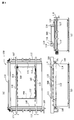
- FIG. 1 is a diagram showing a configuration of an inspection apparatus according to the present invention, where (a) is a plan view, (b) is a front view, and (c) is a right side view.
- 2A and 2B are diagrams showing the configuration of a camera and a camera driving device of a solar cell inspection device, where FIG. 2A is a plan view, FIG. 2B is a cross-sectional view taken along the line A-A in FIG. BB right sectional drawing of (b) is a figure which shows the part in charge of each camera in the case of image
- an opening 112 is formed in a square box-shaped dark room 110 and a flat upper surface 111 thereof.
- the opening 112 is formed in a part of the upper surface of the dark room 110 in consideration of the size of the DUT 200.
- three cameras 121, 122, and 123 for inspecting and measuring the solar cell that is the object to be measured 200, and these moving means are provided in the darkroom.
- the moving means of the cameras 121, 122, 123 may not be provided depending on the application.
- the light shielding material that does not allow light to enter the dark room 110 is used.
- the entire top surface 111 including the device under test 200 may be covered with the light shielding means after the solar cell is placed on the top surface 111 as the device under test 200, the entire top surface 111 may be the opening 112. .
- the four side surfaces and the bottom surface other than the top surface are all light-shielding members.
- a pair of guide members 114 that guide the conveyance of the DUT 200 is provided on the upper surface 111. The distance between the guide members 114 and 114 can be changed according to the size of the DUT 200.
- the guide members 114 are elongated rails having a rectangular cross section, and a pair of guide members 114 are provided on the upper surface of the inspection apparatus 100 according to the present invention along the flow direction of the measured object 200.
- a plurality of rollers 115 are arranged on the inner side surface of each guide member 114, and the object to be measured 200 is moved and conveyed on the rollers 115.
- the guide member 114 and the plurality of rollers 115 constitute support means for holding the solar cell panel 30 on the opening 112. Therefore, the measured object 200 does not fall into the dark room 110 from the opening 112 while the measured object 200 is being conveyed and measured.
- the guide member 114 can be adjusted in accordance with the width dimension of the object 200 to be measured by the moving rail 116, the feed screw 117, and the handle 118 arranged on the carry-in side and the carry-out side of the object 200 to be measured. It has become. That is, one of the feed screws 117 is a right-hand thread and the other is a left-hand thread. By rotating the handle 118, the guide members 114 and 114 approach and separate from each other with a constant center position. It is like that. Further, the feed screw 117 on the carry-in side and the carry-out side are connected by a cross shaft 113 provided with a bevel gear, and by rotating the handle 118, both the feed screws 117 can be rotated simultaneously by the bevel gear.
- the positioning bracket 119 On one side of the conveyance guide 114, there is a positioning bracket 119 that can be taken in and out by an actuator or the like, and the object to be measured 200 is positioned in the conveyance direction by projecting the positioning bracket 119.
- the positioning bracket 119 is not configured to be taken in and out from the side surface of the guide member 114, but may be configured to be moved up and down from the upper side of the guide member 114 or to be swung down from the guide member.
- a plurality of positioning fittings 119 may be arranged along the length direction of the guide member 114, and one appropriate positioning fitting 119 may be used according to the change in the size of the DUT 200.
- the positioning bracket 119 itself may be configured to be movable along the length direction of the guide member 114 so that the size of the DUT 200 can be changed.
- Shooting Camera EL light emitted from the DUT 200 is weak light having a wavelength of 1,000 nm to 1,300 nm, and is emitted in a dark room.
- the three shooting cameras 121, 122, and 123 are used. Shoot this faint light.
- a model C9299-02 Si-CCD camera manufactured by Hamamatsu Photonics is used.
- FIG. 2A and 2B are diagrams showing the configuration of the camera moving means, where FIG. 2A is a plan view, FIG. 2B is a cross-sectional view taken along the line A-A in FIG. BB right sectional drawing of (b) is a figure which shows the part in charge of each camera in the case of image
- the cameras 121, 122, 123 in the dark room 110 are arranged and fixed upward on a support beam 130 as support means, and the central camera 122 is arranged so as to be the center of the guide members 114, 114. 121 and 123 are arranged equidistant from the central camera 122.
- Both ends of the support beam 130 are supported by y-axis guide portions 140 and 140 that move the cameras 121, 122, and 123 in the y-axis direction.
- the support beam 130 can advance and retreat along the y-axis direction on the y-axis guide portion 140 by the motor 142 and the timing belts 144 and 144 on both sides.
- the y-axis guide portions 140 and 140, the motor 142, and the timing belts 144 and 144 constitute moving means for the cameras 121, 122, and 123.
- various linear actuators can be used for the y-axis guide parts 140 and 140, in this embodiment, a ball screw is used.
- the drive system is not limited to the above embodiment using a motor and a ball screw, and various linear actuators can be used.
- the cameras 121, 122, and 123 are moved to arbitrary positions on the y axis by controlling the rotation of the motor 142 of the moving means. As shown in FIG. 2D, the cameras 121, 122, and 123 are the six responsible portions obtained by dividing the DUT 200 into two in the y-axis direction of the apparatus and three in the x-axis direction of the apparatus. The camera moves in the y-axis direction and shoots in two steps indicated by reference numerals 1 and 2.
- the number of cameras, the number of times of movement (number of times of photographing), and the direction of movement are examples, and can be variously selected according to the purpose.
- one moving unit is sufficient for a plurality of cameras.
- the multiple cameras all move in the same direction and the same distance all at once. Since the moving means need only be able to advance and retreat in the y-axis direction, the structure becomes simple and can be manufactured at low cost.
- Light-shielding means Although it is a light-shielding means, it has been described above that it covers the entire upper surface 111 of the dark room. However, in the case of the solar cell panel 30, the resin-made back material 22 on the back side is opaque and has sufficient light shielding properties.
- the upper surface 111 of the dark room 110 is also made of a light shielding member except for the opening 112. Therefore, when the device under test 200 is larger than the opening 112 and the peripheral portion of the opening 112 is in close contact with the blank portion 30a of the solar cell panel 30, the entire opening 112 is covered with the device under test 200.
- the light shielding means is unnecessary. However, when the object to be measured 200 is smaller than the opening 112, or when the object to be measured 200 is not closely attached to the opening 112 and is supported away, light enters the dark room 110 through the gap. It is necessary to cover with light means.
- the light shielding means various forms such as, for example, a cover that covers the entire upper surface of the dark room 110 with a light shielding cover can be adopted.
- the solar cell panel 30 is taken as an example of the object to be measured 200, and the usage method of the solar cell inspection device 100 of the present invention will be described.
- the solar cell panel 30 manufactured and carried out by a laminating apparatus or the like is then conveyed to the front of the solar cell inspection apparatus 100 of the present invention by a conveyor or the like.
- the conveyed solar cell panel is guided between a pair of guide members 114 and 114 and moves on a roller 115 provided inside the guide member to reach the dark room 110.
- the positioning member 119 provided so as to be able to be taken in and out by an actuator or the like is projected on the side surface of the guide member 114, thereby positioning in the transport direction.
- the DUT 200 including the solar cell panel 30 that has reached a predetermined position in the dark room 110 is stopped on the opening 112 of the dark room 110 with the transparent cover glass 21 facing downward, and is connected to a power source (not shown). Is done. Since the DUT 200 is smaller than the opening 112, light enters the dark room from the surroundings, and therefore, the entire upper surface of the dark room 110 is covered from above the DUT 200 with a light shielding unit (not shown). A forward current is passed through the DUT 200 from the power source.
- the cameras 121, 122, and 123 are used for photographing. As shown in FIG. 2D, each of the cameras 121, 122, and 123 uses two of the six assigned portions of the DUT 200 as assigned portions. Each camera 121, 122, 123 is moved along the y-axis by the moving means, and images are taken twice as indicated by reference numerals 1 and 2 to obtain a total of six responsible portion images. If each image is overlapped little by little at a boundary portion with an adjacent image, the image data of each camera can be easily combined with the image of one solar cell panel. Since a plurality of cameras are used, the cameras can be arranged close to the device under test 200, and the height of the dark room 110 can be reduced.
- the number of cameras is not limited to three, and generally a plurality of cameras may be used.
- the camera is arranged in the x-axis direction and the camera is moved in the y-axis direction.
- the camera may be arranged in the y-axis direction and moved in the x-axis direction.
- each camera captures the object 200 to be measured from close, so that a clear image can be obtained.
- the area of the portion in charge of photographing per camera is small, the entire object to be measured 200 can be photographed in a short time.
- the cameras 121, 122, and 123 are spaced apart from each other in the x-axis direction, the object to be measured 200 is divided into three equal parts in the length direction, and one-third is taken for shooting. If the entire measurement object 200 is photographed, the moving means becomes unnecessary. If the moving means becomes unnecessary, the cameras 121, 122, and 123 can be fixed to the bottom of the dark room 110 and photographed.
- the device under test 200 is the solar battery panel 30, but is not limited to this, and the device under test 200 includes only one solar cell 28 or the solar cell 28. A plurality of strings 25 connected by lead wires 29 may be used.
- the image processing apparatus analyzes a portion that does not emit light for each solar battery cell 28 from the image of the solar battery panel, determines pass / fail for each solar battery cell 28, and determines whether the solar cell 28 has passed or failed for the solar cell 28. The acceptance / rejection of the battery panel 30 as a whole is determined.
- the cameras 121, 122, and 123 may also be photographed for each solar cell by increasing the number of cameras and the number of movements, or several solar cells may be photographed.
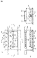
- FIG. 3 is a diagram showing an embodiment of the present invention in which the dark room can be further reduced in size, (a) is a plan view, and (b) is a diagram of (a).
- (c) is DD right sectional drawing of (a).
- a support beam 130 as a support means, and three cameras 121, 122, 123 are supported sideways here. Both ends of the support beam 130 are supported by the x-axis guide portions 140 and 140, and the cameras 121, 122, and 123 can be simultaneously advanced and retracted along the y-axis by the motor 142 and the timing belts 144 and 144. .
- reflectors 131, 132, 133 made of aluminum or the like provided to be inclined with respect to the opening 112 are provided in front of each camera.
- Each reflector 131, 132, 133 is integrated with the corresponding camera 121, 122, 123, and moves forward and backward along the y axis together with the camera 121, 122, 123.
- Each camera captures the reflected light from the part in charge of the object to be measured reflected from each reflector as an image of a part of the object to be measured 200, and repeats the movement to move all the parts in charge. And an entire captured image of the object 200 is obtained from the entire image of each camera.
- the distance from each camera to the object 200 to be measured is always constant.
- a configuration may be adopted in which the camera is fixed to one end of the dark room sideways, and only the reflector is moved by the moving means.
- FIG. 4 is a diagram showing an embodiment in which the camera is rocked as a moving means of the camera, where (a) is a plan view and (b) is E in (a). -E sectional view, (c) is a right sectional view of FF of (a), and (d) is a diagram showing a portion in charge of each camera when photographing the object to be measured.
- a transparent plate 108 is attached to the opening above the dark room 110.
- the opening 112 may be used without attaching the transparent plate 108 as in the above-described embodiment.
- the transparent plate 108 may be attached and sealed in the opening 112 of the above-described embodiment.
- the transparent plate 108 a glass plate, a synthetic resin plate such as acrylic, or the like can be used. 2 and 3, the transparent plate 108 may be attached to the opening on the upper surface of the dark room 110.
- the transparent plate 108 is attached to the opening 112
- dust and the like can be prevented from entering the dark room 110, and the dark room 110 and the camera can be prevented from becoming dirty.
- EL light emission from the solar cell panel is weak, so that the presence of the transparent plate 108 attenuates and makes it difficult to take a picture.
- four cameras 121, 122, 123, and 124 are arranged in the x-axis direction. The four cameras are fixed on a support beam 150 as support means, and the support beam 150 is shown in FIG.
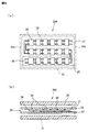
- FIG. 5 is a diagram showing an embodiment in which only the reflector is oscillated, where (a) is a plan view and (b) is a GG in (a). Sectional drawing and (c) are HH right sectional views of (a).
- the dark room there is a support beam 150 as support means, and four reflectors 131, 132, 133, and 134 are supported here.
- the reflecting plates 131, 132, 133, and 134 can be swung within a range of 131 ′ to 131 ′′ as shown in FIG. 5C by the swinging means 151 at both ends of the support beam 150.
- the cameras 121, 122, 123, and 124 are fixed laterally on the right side of a dark room floor or the like.
- the reflectors 131, 132, 133, and 134 are simultaneously rotated in the same direction by the same angle. According to this configuration, the cameras 121, 122, 123, and 124 are fixed, and only the lightweight reflectors 131, 132, 133, and 134 need to be oscillated. be able to.
Landscapes
- General Physics & Mathematics (AREA)
- Physics & Mathematics (AREA)
- Life Sciences & Earth Sciences (AREA)
- Immunology (AREA)
- Analytical Chemistry (AREA)
- Biochemistry (AREA)
- General Health & Medical Sciences (AREA)
- Chemical & Material Sciences (AREA)
- Health & Medical Sciences (AREA)
- Pathology (AREA)
- Sustainable Development (AREA)
- Spectroscopy & Molecular Physics (AREA)
- Photovoltaic Devices (AREA)
- Investigating Materials By The Use Of Optical Means Adapted For Particular Applications (AREA)
- Investigating, Analyzing Materials By Fluorescence Or Luminescence (AREA)
- Testing Of Optical Devices Or Fibers (AREA)
Abstract
Description
出力特性は、光照射下において、太陽電池の電流電圧特性を測定する光電変換特性として行われる。光源としては、太陽光が望ましいのであるが、天候により強度が変化することから、ソーラーシミュレーターが使用されている。ソーラーシミュレーターでは、太陽光に代えてキセノンランプやメタルハライドランプ等を使用している。また、これらの光源を長時間点灯していると、温度上昇などにより光量が変化する。そこで、これらのランプのフラッシュ光を用い、横軸を電圧、縦軸を電流として、収集したデータをプロットすることにより太陽電池の出力特性曲線を得ている(例えば、特許文献1参照)。
ソーラーシミュレーターと異なる方法として、特許文献2では、シリコンの多結晶型の太陽電池素子に対して順方向に電圧を印加することで、エレクトロルミネッセンス(EL)を生じさせる方法を提案している。また、薄膜型の太陽電池でも同様のことが生じる。太陽電池素子から発光されるELを観察することによって、電流密度分布が分かり、電流密度分布の不均一から太陽電池素子の欠陥を知ることができる。すなわち、発光しない部分が欠陥部分と判断でき、この欠陥部分の面積が予め決められた量より少なければ、所定の発電能力を有するものと判断できることになる。
図7は、特許文献2に記載された検査装置の構成を模式的に示す図である。検査装置10は、暗室11と、この暗室11の上部に設けられたCCDカメラ12と、暗室11の床面に載置された太陽電池セル13に電流を流す電源14と、CCDカメラ12からの画像信号を処理する画像処理装置15とから構成されている。
暗室11には窓11aがあり、ここにCCDカメラ12のファインダー12aがあって、ここから肉眼で覗くことで、CCDカメラ12の撮影画像を確認することができる。画像処理装置15としては、パソコンを使用している。
しかし、太陽電池パネルになると、2m×1m程度の大きさとなり、暗室11もこれを収容できる大きさが必要となる。また、被測定物となる太陽電池パネルは、暗室内に入れなければCCDカメラ12で撮影できないので、暗室に太陽電池パネルの出し入れができる扉を設けなければならない。検査装置をこのような暗室内に搬入する構成とすると、設置した扉が閉じた場合の遮光性も確保しなければならない。また検査装置に搬入された太陽電池の位置決め部材や搬送ガイド部材も暗室内に設ける必要がある。さらに、太陽電池に電流を通すための通電手段も暗室内に設ける必要がある。という具合に構造的に複雑になり、高価なものとなる。
また、1台のカメラで大きな太陽電池パネルを撮影するには、カメラから太陽電池パネルまでの距離を大きく取らなければならず、暗室が大型化してしまう。カメラを移動しながら太陽電池パネルを一部づつ複数回に分けて撮影すれば、カメラと太陽電池パネルとの距離を小さくして暗室を小型化できるが、検査に時間が掛かってしまう、という問題が起こる。さらに、検査時間を短縮するために撮影回数を減らすと、1画像で撮影される太陽電池パネルの面積が大きくなって、撮影した画像の解像度が粗くなってしまい欠陥を正確に検査できないという問題もある。
本発明は、斯かる実情に鑑みてなされたもので、太陽電池に順方向の電流を流してEL発光させる検査装置であって、構造が簡単で、しかも、撮影した画像の解像度が良好な状態での欠陥検査の検査時間を短縮することができる太陽電池の検査装置を提供することを目的としている。
また、前記暗室内に、前記複数のカメラを移動する移動手段を設けた構成としたり、前記移動手段が、前記複数のカメラを固定する支持部材を有し、該支持部材を直線的に進退させる構成としたり、前記複数のカメラのそれぞれに、前記担当部分を撮影する反射板を設けた構成とすることができる。前記移動手段が、前記カメラと共に反射板も移動する構成としてもよい。さらに、前記暗室内に、前記複数のカメラをそれぞれ揺動する揺動手段を設け、各カメラが揺動することで、前記担当部分を撮影する構成としてもよい。
あるいは、前記複数のカメラのそれぞれに、前記担当部分を撮影する反射板を設け、該反射板を揺動する揺動手段を設けた構成としてもよい。さらに、前記開口部を透明板で閉塞した構成にすることもできる。
太陽電池は、暗室の外から暗室の上面に載せることで検査でき、被測定物としての太陽電池を暗室に出し入れするための扉を設ける必要がない。そのため、暗室を小型化でき、その構造を簡単にすることができる。
複数のカメラで、太陽電池を分割して担当部分だけを撮影するので、撮影した画像の解像度が良好な状態で欠陥検査を短時間に撮影することができる。また、撮影対象面積が小さくなるので、カメラと太陽電池との距離を小さくすることができ、暗室も小型化でき、安価にできる。前記移動手段が、前記複数のカメラを固定する支持部材を有し、該支持部材を直線的に進退させることによって、複数のカメラを同時に同方向に同じ速度で移動することができ、移動手段を1つにして安価に製作することができる。
さらに太陽電池パネルの場合、製造ライン(ラミネート装置などの製造装置など)では、受光面を下にして搬送される。したがって本発明の検査装置を暗室上面に開口部を設ける構成とすることにより、太陽電池パネルを反転することなく本検査装置に載せることができる。これに加え、開口部に対して傾斜した反射板を設け、これに映った像をカメラで撮影することにすれば、さらに暗室を小型にすることができる。複数のカメラで撮影することで、撮影した画像の解像度が良好な状態で検査時間を短縮できるので、本発明の検査装置を、太陽電池パネルの製造ラインにいれても、欠陥検査の精度を良好な状態に維持してタクトタイムを短くすることができる。
図2は、太陽電池の検査装置のカメラと移動手段の構成を示す図で、(a)は平面図、(b)は(a)のA−A断面図、(c)は(a)のB−B右断面図、(d)は被測定物を撮影する場合の各カメラの担当部分を示す図である。
図3は、暗室をさらに小型にできるようにした本発明の実施の形態を示す図で、(a)は平面図、(b)は(a)のC−C断面図、(c)は(a)のD−D右断面図である。
図4は、カメラの移動手段として、カメラを揺動する実施の形態を示す図で、(a)は平面図、(b)は(a)のE−E断面図、(c)は(a)のF−F右断面図、(d)は被測定物を撮影する場合の各カメラの担当部分を示す図である。
図5は、反射板のみを揺動する実施の形態を示す図で、(a)は平面図、(b)は(a)のG−G断面図、(c)は(a)のH−H右断面図である。
図6は、本発明の検査装置にて測定する太陽電池の構成の説明図で(a)は平面図、(b)は断面図である。
図7は、従来の太陽電池の検査装置の構成を模式的に示す図である。
108 透明板
110 暗室
111 上面
112 開口部
114 ガイド部材(支持部材)
115 ローラ(支持部材)
119 位置決め金具
121、122、123、124 カメラ
130、150 支持梁(支持手段)
140 x軸ガイド部(移動手段)
142 モータ(移動手段)
144 タイミングベルト(移動手段)
200 被測定物
131、132、133 反射板
151 揺動手段
<1>被測定物(太陽電池モジュール)
まず本発明の検査装置が扱う対象である被測定物200の例について説明する。図6は、本発明の検査装置にて測定する太陽電池の構成の説明図で、(a)は、太陽電池の内部の太陽電池セルが分かるように記載した平面図で、(b)はその断面図である。
図6(a)の平面図に示す様に、被測定物200である太陽電池モジュールは角型の太陽電池セル28がリード線29により複数個直列に接続されたストリング25を形成し、さらにそのストリングを複数列リード線29により接続した構成となっている。
被測定物200である太陽電池としては、太陽電池セル28が1枚のみ、太陽電池セル28を複数枚直線的につないだストリング25、ストリング25を平行に複数列並べ、太陽電池セル28がマトリックス状に配置された太陽電池パネル30のいずれでもよい。図に示すように、太陽電池パネル30は、その周縁部に太陽電池セル28などの受光面とはならない余白部分30aを有している。
また被測定物200の断面構造は、図6(b)に示す様に、上側に配置された裏面材22と下側に配置された透明カバーガラス21の間に、充填材23、24を介して複数列のストリング25をサンドイッチにした構成を有する。
裏面材22は例えばポリエチレン樹脂などの材料が使用される。充填材23、24には例えばEVA樹脂(ポリエチレンビニルアセテート樹脂)などが使用される。ストリング25は、上記のように電極26、27の間に、太陽電池セル28をリード線29を介して接続した構成である。
このような太陽電池モジュールは、上記のように構成部材を積層しラミネート装置などにより、真空の加熱状態下で圧力を加え、EVAを架橋反応させてラミネート加工して得られる。
また被測定物200としては、一般に薄膜式と呼ばれる太陽電池を対象とすることができる。
この薄膜式の代表的な構造例では、下側に配置された透明カバーガラスには、予め透明電極、半導体、裏面電極からなる発電素子が蒸着してある。そして、このような薄膜型太陽電池モジュールを、透明カバーガラスを下向きに配置し、ガラス上の太陽電池素子の上に充填材を被せ、更に、充填材の上に裏面材を被せた構造で、同じようにラミネート加工することにより得られる。
このように被測定物200としての薄膜式の太陽電池モジュールは、結晶系セルが蒸着された発電素子に変わるだけで、基本的な封止構造は前記した結晶系セルの場合と同じである。
<2>検査装置の全体構造
図1は本発明の検査装置の構成を示す図で、(a)は平面図、(b)は正面図、(c)は右側面図である。図2は、太陽電池の検査装置のカメラとカメラ駆動装置の構成を示す図で、(a)は平面図、(b)は(a)のA−A断面図、(c)は(a)のB−B右断面図、(d)は被測定物を撮影する場合の各カメラの担当部分を示す図である。これらの図に示す本発明の太陽電池の検査装置100は、四角の箱形の暗室110およびその平らな上面111に、開口部112が穿設されている。開口部112は、被測定物200の大きさを考慮して暗室110の上面の一部に形成している。暗室内には、被測定物200である太陽電池を検査測定する3台のカメラ121、122、123と、これらの移動手段が設けられている。ただし、カメラ121、122、123の移動手段については用途に応じて設けない場合もある。上面111の開口部112以外は、暗室110に光を入れないような遮光性の素材からなる構成にしている。もっとも、上面111に被測定物200として太陽電池を載せた後、被測定物200を含む上面111の全体を、遮光手段にて覆うことにすれば、上面111全体を開口部112にしてもよい。また、上面以外の4つの側面と底面は全て遮光性の部材としている。上面111には、被測定物200の搬送をガイドする一対のガイド部材114が設けられている。ガイド部材114、114間の距離は、被測定物200のサイズに合わせて変更可能である。
<3>被測定物の搬送ガイドおよび位置決め
ガイド部材114は、矩形断面の細長いレール状で、本発明の検査装置100の上面に、被測定物200の流れ方向に沿って一対設けられている。各ガイド部材114の内側側面には、複数個のローラ115が配置され被測定物200は、このローラ115上を移動搬送される。ガイド部材114と複数個のローラ115とで、太陽電池パネル30を開口部112の上に保持する支持手段を構成している。したがって被測定物200を搬送中および測定中に被測定物200が開口部112から暗室110内に落下することはない。またこのガイド部材114は、装置の被測定物200の搬入側および搬出側に配置された移動用レール116、送りネジ117およびハンドル118により被測定物200の幅寸法に応じて調整が可能な構成となっている。すなわち、送りネジ117は、一方が右ネジで他方が左ネジとなっており、ハンドル118を回転することで、ガイド部材114、114は、中心位置が一定の状態で、相互に接近・離反するようになっている。また、搬入側および搬出側の送りネジ117は、傘歯車を備えたクロスシャフト113により連結され、ハンドル118を回転することで、両方の送りネジ117を傘歯車によって同時に回転することができる。
一方の搬送ガイド114の側面には、アクチュエーター等により出し入れ可能な位置決め金具119があり、搬送された被測定物200は、この位置決め金具119を突出させることにより搬送方向の位置決めがされる。位置決め金具119は、ガイド部材114の側面から出し入れする構成ではなく、ガイド部材114の上方から上下させる方法またガイド部材から旋回下降させるなどの構成とすることも可能である。位置決め金具119をガイド部材114の長さ方向に沿って複数個配置し、被測定物200のサイズの変更に応じて適当な1つの位置決め金具119を使用するようにするとよい。あるいは、位置決め金具119自身をガイド部材114の長さ方向に沿って移動可能な構成にし、被測定物200のサイズの変更に応じられるようにしてもよい。
<4>撮影用カメラ
被測定物200から発するEL発光は、1,000nmから1,300nmの波長の微弱な光であり、暗室内で発光させ、3台の撮影用カメラ121、122、123でこの微弱な光を撮影する。このため、撮影用カメラ121、122、123としては微弱な光に対する感度の良いCCDカメラを用いる必要がある。本実施の形態例では、浜松ホトニクス製の型式C9299−02(Si−CCDカメラ)を使用している。
<5>カメラの移動手段
図2は、カメラの移動手段の構成を示す図で、(a)は平面図、(b)は(a)のA−A断面図、(c)は(a)のB−B右断面図、(d)は被測定物を撮影する場合の各カメラの担当部分を示す図である。暗室110内のカメラ121、122、123は、支持手段としての支持梁130上に上向きに配置・固定され、中央のカメラ122がガイド部材114、114の中央になるように配置され、両側のカメラ121、123が中央のカメラ122から等距離離れて配置されている。支持梁130の両端は、カメラ121、122、123をy軸方向に移動するy軸ガイド部140、140に支持されている。そして、モータ142と両側のタイミングベルト144、144とによって、支持梁130は、y軸ガイド部140上を、y軸方向に沿って進退可能となっている。以上の構成において、y軸ガイド部140、140、モータ142、タイミングベルト144、144とで、カメラ121、122、123の移動手段を構成している。y軸ガイド部140、140は、各種のリニアアクチュエータを使用することができるが、この実施例では、ボールネジを使用している。
ただし、駆動方式は、モータ及びボールネジを使用した上記の実施例に限定されるものではなく、各種のリニアアクチュエータを使用することができる。
移動手段のモータ142を回転制御することで、カメラ121、122、123を、y軸上の任意の位置に移動する。図2(d)に示すように被測定物200を装置のy軸方向に2つ、装置のx軸方向に3つに分けた6個の担当部分を、カメラ121、122、123は、装置のy軸方向に移動して符号1、2で示す2回に分けて撮影するようになっている。上記のカメラの数や移動回数(撮影回数)及び移動方向は、一例であり、目的に合わせて種々選択することができる。
本発明では、複数台のカメラに対し、1つの移動手段で足りる。複数台のカメラは、全て一斉に同じ方向、同じ距離だけ移動することになる。移動手段としても、y軸方向の進退だけ出来ればよいので、構造が簡単になり、安価に製造できる。
<6>遮光手段
遮光手段であるが、上記では、暗室の上面111の上部全てを覆うと説明していた。しかし太陽電池パネル30の場合、裏側の樹脂製の裏面材22は、不透明であり、遮光性が十分である。また、暗室110の上面111も、開口部112以外は遮光性の部材で構成されている。したがって、被測定物200が開口部112より大きくて、開口部112の周縁部が、太陽電池パネル30の余白部分30aに密着する場合は、開口部112の全体が被測定物200で覆われるので、遮光手段は不要である。
しかし、被測定物200の方が開口部112より小さい場合や、開口部112の上に密着しておらずに離れて支持されている場合等には、隙間から光が暗室110内に入るので、光手段で覆う必要がある。遮光手段としては、たとえば、暗室110の上面全てを遮光カバーで覆うものなど、多様な形態が採用可能である。
<7>その他機器
上記の他に、図示を省略するが、図7の従来例で示した電源14やパソコンを利用した画像処理装置15が設けられている。
<8>検査装置の使用方法
被測定物200として太陽電池パネル30を例にして、本発明の太陽電池の検査装置100の使用方法を説明する。
ラミネート装置などで製造され搬出された太陽電池パネル30は、次に、コンベアなどで本発明の太陽電池の検査装置100の手前まで搬送される。搬送されてきた太陽電池パネルは、一対のガイド部材114、114の間でガイドされガイド部材の内側に設けられたローラ115上を移動して暗室110の上に達する。その後ガイド部材114の側面にアクチュエーター等により出し入れ可能に設けられた位置決め金具119を突出させることにより搬送方向の位置決めがされる。
暗室110の所定の位置に達した太陽電池パネル30からなる被測定物200は、透明カバーガラス21を下に向けて暗室110の開口部112の上で停止し、図示しない電源との間で接続がされる。被測定物200の方が開口部112より小さいので、周囲から暗室内に光が入るから、被測定物200の上から暗室110の上面全体を図示しない遮光手段で覆う。被測定物200に電源から順方向の電流を流す。被測定物200がEL発光するので、カメラ121、122、123で撮影する。
各カメラ121、122、123は、図2(d)に示すように、被測定物200の6個の担当部分のうち2個を担当部分とする。そして、各カメラ121、122、123は、移動手段でy軸に沿って移動し、符号1、2に示すように2回撮影することで合計6個の担当部分の画像を得る。各画像は、隣接する画像との境界部分ですこしずつオーバーラップするようにしておくと、各カメラの画像データを1枚の太陽電池パネルの画像に合成し易くなる。
カメラを複数台にしたので、カメラを被測定物200に近接して配置することができ、暗室110の高さを小さくすることができる。なお、カメラの数は、3台に限定されるものではなく、一般に複数台あればよい。また、上記の実施例では、x軸方向にカメラを配置し、y軸方向にカメラを移動したが、逆にy軸方向にカメラを配置して、x軸方向に移動してもよい。
また、各カメラは、被測定物200を近くから撮影するので、鮮明な画像を得ることができる。さらに、カメラ1台当たりの撮影する担当部分の面積が小さいことから、短時間で被測定物200全体の撮影が可能となる。
カメラ121、122、123を、たとえば、x軸方向に離間して配置し、被測定物200を長さ方向に3等分し、1/3づつ分担して撮影し、1回の撮影で被測定物200全体を撮影すれば、移動手段は不要となる。移動手段が不要になれば、カメラ121、122、123を暗室110の底部に固定して撮影することができる。
上記の実施の形態例では、被測定物200は、太陽電池パネル30であるが、これに限定されず、被測定物200を、太陽電池セル28を1枚だけにしたり、太陽電池セル28を複数個リード線29で接続したストリング25にしたりしてもよい。
画像処理装置は、太陽電池パネルの画像から各太陽電池セル28について、発光しない部分を分析し、太陽電池セル28ごとの合否を判断し、全ての太陽電池セル28についての合否の結果から、太陽電池パネル30全体としての合否を判断する。
なお、カメラ121、122、123による撮影も、カメラの台数や移動回数を増やして太陽電池セル1枚ごとに撮影してもよいし、太陽電池セルを数枚ずつ撮影することもできる。
<9>反射板を使用した実施の形態
図3は、暗室をさらに小型にできるようにした本発明の実施の形態を示す図で、(a)は平面図、(b)は(a)のC−C断面図、(c)は(a)のD−D右断面図である。暗室内部には、支持手段としての支持梁130があり、ここに3台のカメラ121、122、123が横向きに支持されている。支持梁130の両端は、x軸ガイド部140、140に支持され、モータ142、タイミングベルト144、144によって、カメラ121、122、123を一斉にy軸に沿って同じ距離だけ進退させることができる。以上は、図2の実施例と同じである。
本発明の実施の形態では、各カメラの前に、開口部112に対して傾斜するように設けられたアルミニウム製等の反射板131、132、133を設けている。各反射板131、132、133は、対応するカメラ121、122、123と一体になっており、カメラ121、122、123と一緒にy軸に沿って進退する。そして、各カメラは、各反射板から反射される被測定物の担当部分からの反射光を、被測定物200の一部の画像として撮影し、移動をすることによって繰り返して、担当部分の全てを撮影し、各カメラの画像全体で被測定物200の全体の撮影画像を得る。このような構成では、各カメラから被写体となる被測定物200までの距離が常に一定になっている。
図示は省略するが、カメラを暗室の一方端に横向きに固定し、反射板のみを移動手段で移動する構成としてもよい。
<10>カメラを揺動する実施の形態
図4は、カメラの移動手段として、カメラを揺動する実施の形態を示す図で、(a)は平面図、(b)は(a)のE−E断面図、(c)は(a)のF−F右断面図、(d)は被測定物を撮影する場合の各カメラの担当部分を示す図である。この実施例では、暗室110上部の開口部に、透明板108を取り付けている。ただし、この透明板108を取り付けずに、前述した実施例と同じく、開口部112としてもよい。逆に、前述した実施例の開口部112に透明板108を取り付けて封鎖してもよい。透明板108としては、ガラス板、アクリルなどの合成樹脂板等を使用することができる。尚図2および図3で説明した実施形態においても暗室110上面の開口部に、透明板108を取り付けた構成としてもよい。
開口部112に透明板108を取り付けると、暗室110内部にゴミなどが入り込むのを防止でき、暗室110内やカメラが汚れることを防止することができる。一方、太陽電池パネルからのEL発光は微弱なので、透明板108があると減衰され、撮影しにくくなるため、透明板108が無い方がよいという場合もある。
この実施例では、4台のカメラ121、122、123、124をx軸方向に配置している。4台のカメラは、支持手段としての支持梁150上に固定され、支持梁150は、両端にある公知の揺動手段151によって、カメラ121、122、123、124を図4(c)に示すように、121’~121”の範囲で揺動できるようになっている。
カメラ121、122、123、124は、図4(d)に示すように、y軸と平行な線で分割された担当部分を担当する。そして、カメラを中央に向けて図4(d)の符号1で示す中央部分の4つの担当部分を撮影をする。次に、揺動手段151によって図4(c)の121”の位置に揺動することで、符号2で示す4つの担当部分を撮影をし、図4(c)の121’の位置に揺動することで、符号3で示す4つの担当部分を撮影をする。被測定物200全体を合計12個の担当部分を撮影し測定することができる。各画像は、隣接する画像と周辺部でオーバーラップしており、全画像を接続することで被測定物200全体の画像を得ることができる。この揺動手段151は、構造が単純なので、安価に製造することができる。
<11>反射板のみを揺動する実施の形態
図5は、反射板のみを揺動する実施の形態を示す図で、(a)は平面図、(b)は(a)のG−G断面図、(c)は(a)のH−H右断面図である。暗室内部には、支持手段としての支持梁150があり、ここに4枚の反射板131、132、133、134が支持されている。支持梁150の両端にある揺動手段151によって、反射板131、132、133、134を図5(c)に示すように、131’~131”の範囲で揺動できるようになっている。
カメラ121、122、123、124は、図5(c)に示すように、暗室の床等の右側に横向きに固定されている。反射板131、132、133、134は、一斉に同じ方向に同じ角度だけ回転することになる。
この構成によれば、カメラ121、122、123、124は固定されており、軽量な反射板131、132、133、134のみを揺動すればよいので、可動部が軽くなり、安価に製造することができる。
Claims (8)
- 上面に開口部を有する暗室と、該暗室の前記上面に設けられ、被測定物となる太陽電池を前記開口部上に保持する支持手段と、前記暗室の内部に設けられ、前記被測定物を撮影する複数のカメラと、を有し、各カメラが前記太陽電池の担当部分を撮影することで、太陽電池の全体を撮影することを特徴とする太陽電池の検査装置。
- 前記暗室内に、前記複数のカメラを移動する移動手段を設けたことを特徴とする請求項1に記載の太陽電池の検査装置。
- 前記移動手段が、前記複数のカメラを固定する支持部材を有し、該支持部材を直線的に進退させることを特徴とする請求項2に記載の太陽電池の検査装置。
- 前記複数のカメラのそれぞれに、前記担当部分を撮影する反射板を設けたことを特徴とする請求項1から3のいずれかに記載の太陽電池の検査装置。
- 前記移動手段が、前記カメラと共に反射板も移動することを特徴とする請求項4記載の太陽電池の検査装置。
- 前記暗室内に、前記複数のカメラをそれぞれ揺動する揺動手段を設け、各カメラが揺動することで、前記担当部分を撮影することを特徴とする請求項1に記載の太陽電池の検査装置。
- 前記複数のカメラのそれぞれに、前記担当部分を撮影する反射板を設け、該反射板を揺動する揺動手段を設けたことを特徴とする請求項1に記載の太陽電池の検査装置。
- 前記開口部を透明板で閉塞したことを特徴とする請求項1から7のいずれかに記載の太陽電池の検査装置。
Priority Applications (3)
| Application Number | Priority Date | Filing Date | Title |
|---|---|---|---|
| EP09810094.4A EP2330631A4 (en) | 2008-08-28 | 2009-08-26 | DEVICE FOR THE INVESTIGATION OF A SOLAR BATTERY |
| CN200980143209.0A CN102197494B (zh) | 2008-08-28 | 2009-08-26 | 太阳能电池检测装置 |
| US13/061,496 US8604819B2 (en) | 2008-08-28 | 2009-08-26 | Inspecting apparatus for photovoltaic devices |
Applications Claiming Priority (2)
| Application Number | Priority Date | Filing Date | Title |
|---|---|---|---|
| JP2008218927A JP2010056252A (ja) | 2008-08-28 | 2008-08-28 | 太陽電池の検査装置 |
| JP2008-218927 | 2008-08-28 |
Publications (1)
| Publication Number | Publication Date |
|---|---|
| WO2010024452A1 true WO2010024452A1 (ja) | 2010-03-04 |
Family
ID=41721607
Family Applications (1)
| Application Number | Title | Priority Date | Filing Date |
|---|---|---|---|
| PCT/JP2009/065281 Ceased WO2010024452A1 (ja) | 2008-08-28 | 2009-08-26 | 太陽電池の検査装置 |
Country Status (7)
| Country | Link |
|---|---|
| US (1) | US8604819B2 (ja) |
| EP (1) | EP2330631A4 (ja) |
| JP (1) | JP2010056252A (ja) |
| KR (1) | KR20110069032A (ja) |
| CN (1) | CN102197494B (ja) |
| TW (1) | TWI432758B (ja) |
| WO (1) | WO2010024452A1 (ja) |
Cited By (1)
| Publication number | Priority date | Publication date | Assignee | Title |
|---|---|---|---|---|
| CN102331552A (zh) * | 2011-07-27 | 2012-01-25 | 常州时创能源科技有限公司 | 一种太阳电池检测装置及应用方法 |
Families Citing this family (18)
| Publication number | Priority date | Publication date | Assignee | Title |
|---|---|---|---|---|
| CN102156254B (zh) * | 2011-03-18 | 2012-12-26 | 上海理工大学 | 太阳能电池组件中电池片损坏、老化的自动巡航检测系统 |
| TWI447379B (zh) * | 2011-06-07 | 2014-08-01 | Univ Nat Formosa | 用於太陽能電池內部缺陷的影像處理之電腦程式產品、偵測設備及偵測方法 |
| US8408797B2 (en) * | 2011-09-07 | 2013-04-02 | Alphana Technology Co., Ltd. | Method of manufacturing bearing device component coated with photoluminescence material, bearing device component and processing device with an indicator displaying information for a signal including information in accordance with light emission of a photoluminescence material applied on bearing device |
| CN103033731A (zh) * | 2011-10-08 | 2013-04-10 | 致茂电子股份有限公司 | 太阳能电池检测方法及相关装置 |
| DE102012102456A1 (de) | 2012-03-22 | 2013-09-26 | Komax Holding Ag | Anordnung und Verfahren zum Prüfen eines Solarmoduls |
| KR101256369B1 (ko) * | 2012-05-15 | 2013-04-25 | (주) 에스엘테크 | 다수의 카메라를 이용한 평판 디스플레이 패널 검사 장치 및 방법 |
| KR101256810B1 (ko) * | 2012-07-06 | 2013-04-23 | 주식회사 한국테크놀로지 | El 기법을 이용한 태양전지 검사장치 및 방법 |
| JP2014082352A (ja) * | 2012-10-17 | 2014-05-08 | Npc Inc | 太陽電池の検査装置及びその方法 |
| JP6390354B2 (ja) * | 2014-11-06 | 2018-09-19 | オムロン株式会社 | 端子固定装置および端子固定方法 |
| CN104467664B (zh) * | 2014-11-28 | 2017-11-14 | 苏州晟成光伏设备有限公司 | 高位el检查机 |
| US20190019909A1 (en) * | 2015-12-30 | 2019-01-17 | Corner Star Limited | Advanced interconnect method for photovoltaic strings and modules |
| CN106452357A (zh) * | 2016-09-09 | 2017-02-22 | 海宁正泰新能源科技有限公司 | 一种光伏半成品组件的顶升检查设备 |
| CN108429539A (zh) | 2017-02-14 | 2018-08-21 | 林敬杰 | 电站评估方法与装置 |
| JP6834903B2 (ja) * | 2017-10-20 | 2021-02-24 | トヨタ自動車株式会社 | 検査装置および検査装置故障確認方法 |
| KR102175502B1 (ko) * | 2019-03-28 | 2020-11-06 | 주식회사 에이치비테크놀러지 | 원판과 분판 모두의 세타축 정렬이 가능한 하이브리드형 디스플레이 패널 검사장치 |
| DE102019133738A1 (de) | 2019-12-10 | 2021-06-10 | AIXEMTEC GmbH | Vorrichtung, Verfahren und Verwendung der Vorrichtung zur Justage, Montage und/oder Prüfung eines elektrooptischen Systems |
| CN112278708A (zh) * | 2020-10-16 | 2021-01-29 | 深圳铭薪曙能科技有限公司 | 太阳能电池组件的校正和接地测试系统及其方法 |
| CN116582088B (zh) * | 2023-04-18 | 2024-06-18 | 珠海安维特工程检测有限公司 | 一种光伏系统可靠性能测试装置 |
Citations (9)
| Publication number | Priority date | Publication date | Assignee | Title |
|---|---|---|---|---|
| JP2002148094A (ja) * | 2000-11-10 | 2002-05-22 | Hitachi Ltd | 水位計測方法および装置 |
| JP2006090990A (ja) * | 2004-09-27 | 2006-04-06 | Mitsubishi Heavy Ind Ltd | 透明電極膜基板の検査装置及びその方法並びにプログラム |
| WO2006059615A1 (ja) | 2004-11-30 | 2006-06-08 | National University Corporation NARA Institute of Science and Technology | 太陽電池の評価方法及び評価装置並びにその利用 |
| JP2007088419A (ja) | 2005-06-17 | 2007-04-05 | Nisshinbo Ind Inc | ソーラシミュレータによる測定方法 |
| JP3141553U (ja) * | 2008-02-26 | 2008-05-08 | 日清紡績株式会社 | 太陽電池の検査装置 |
| JP3143169U (ja) * | 2008-04-30 | 2008-07-10 | 日清紡績株式会社 | 太陽電池の検査装置 |
| JP4153021B1 (ja) * | 2007-10-22 | 2008-09-17 | 日清紡績株式会社 | 太陽電池の検査装置 |
| JP2008218927A (ja) | 2007-03-07 | 2008-09-18 | Mitsui Mining & Smelting Co Ltd | フレキシブル配線基材並びに半導体装置及びその製造方法 |
| JP2009065281A (ja) | 2007-09-04 | 2009-03-26 | Sii Ido Tsushin Kk | 携帯端末 |
Family Cites Families (2)
| Publication number | Priority date | Publication date | Assignee | Title |
|---|---|---|---|---|
| JP5236858B2 (ja) * | 2005-02-01 | 2013-07-17 | 日清紡ホールディングス株式会社 | 太陽電池の出力特性の測定方法。 |
| JP4939156B2 (ja) * | 2006-09-19 | 2012-05-23 | 東京エレクトロン株式会社 | 位置合わせ対象物の再登録方法及びその方法を記録した記録媒体 |
-
2008
- 2008-08-28 JP JP2008218927A patent/JP2010056252A/ja active Pending
-
2009
- 2009-08-26 EP EP09810094.4A patent/EP2330631A4/en not_active Withdrawn
- 2009-08-26 US US13/061,496 patent/US8604819B2/en not_active Expired - Fee Related
- 2009-08-26 CN CN200980143209.0A patent/CN102197494B/zh not_active Expired - Fee Related
- 2009-08-26 WO PCT/JP2009/065281 patent/WO2010024452A1/ja not_active Ceased
- 2009-08-26 KR KR1020117007029A patent/KR20110069032A/ko not_active Ceased
- 2009-08-27 TW TW098128822A patent/TWI432758B/zh not_active IP Right Cessation
Patent Citations (9)
| Publication number | Priority date | Publication date | Assignee | Title |
|---|---|---|---|---|
| JP2002148094A (ja) * | 2000-11-10 | 2002-05-22 | Hitachi Ltd | 水位計測方法および装置 |
| JP2006090990A (ja) * | 2004-09-27 | 2006-04-06 | Mitsubishi Heavy Ind Ltd | 透明電極膜基板の検査装置及びその方法並びにプログラム |
| WO2006059615A1 (ja) | 2004-11-30 | 2006-06-08 | National University Corporation NARA Institute of Science and Technology | 太陽電池の評価方法及び評価装置並びにその利用 |
| JP2007088419A (ja) | 2005-06-17 | 2007-04-05 | Nisshinbo Ind Inc | ソーラシミュレータによる測定方法 |
| JP2008218927A (ja) | 2007-03-07 | 2008-09-18 | Mitsui Mining & Smelting Co Ltd | フレキシブル配線基材並びに半導体装置及びその製造方法 |
| JP2009065281A (ja) | 2007-09-04 | 2009-03-26 | Sii Ido Tsushin Kk | 携帯端末 |
| JP4153021B1 (ja) * | 2007-10-22 | 2008-09-17 | 日清紡績株式会社 | 太陽電池の検査装置 |
| JP3141553U (ja) * | 2008-02-26 | 2008-05-08 | 日清紡績株式会社 | 太陽電池の検査装置 |
| JP3143169U (ja) * | 2008-04-30 | 2008-07-10 | 日清紡績株式会社 | 太陽電池の検査装置 |
Non-Patent Citations (1)
| Title |
|---|
| See also references of EP2330631A4 * |
Cited By (1)
| Publication number | Priority date | Publication date | Assignee | Title |
|---|---|---|---|---|
| CN102331552A (zh) * | 2011-07-27 | 2012-01-25 | 常州时创能源科技有限公司 | 一种太阳电池检测装置及应用方法 |
Also Published As
| Publication number | Publication date |
|---|---|
| TW201024771A (en) | 2010-07-01 |
| KR20110069032A (ko) | 2011-06-22 |
| CN102197494B (zh) | 2014-09-03 |
| JP2010056252A (ja) | 2010-03-11 |
| US20110148453A1 (en) | 2011-06-23 |
| TWI432758B (zh) | 2014-04-01 |
| CN102197494A (zh) | 2011-09-21 |
| US8604819B2 (en) | 2013-12-10 |
| EP2330631A1 (en) | 2011-06-08 |
| EP2330631A4 (en) | 2014-06-18 |
Similar Documents
| Publication | Publication Date | Title |
|---|---|---|
| WO2010024452A1 (ja) | 太陽電池の検査装置 | |
| JP4153021B1 (ja) | 太陽電池の検査装置 | |
| JP3143169U (ja) | 太陽電池の検査装置 | |
| TWI447378B (zh) | 太陽能電池的檢查裝置 | |
| CN102007398B (zh) | 太阳电池的检查装置及检查装置用输送装置 | |
| JP2011138981A (ja) | 太陽電池セルの電流電圧出力特性および欠陥の検査装置 | |
| JP5378854B2 (ja) | 太陽電池の検査装置用搬送装置 | |
| JP5006229B2 (ja) | 太陽電池の検査装置 | |
| JP2011082202A (ja) | 検査装置 | |
| KR101564287B1 (ko) | 웨이퍼 검사장치 및 웨이퍼 검사방법 | |
| JP3141553U (ja) | 太陽電池の検査装置 | |
| JP2010021193A (ja) | 太陽電池の検査装置 | |
| JP2012129366A (ja) | 太陽電池の検査装置 | |
| JP2010073701A (ja) | 太陽電池の検査装置、およびその検査装置へ太陽電池を搬入するための取付け具、およびその取付け具を用いた太陽電池の搬入方法 | |
| KR20230065081A (ko) | 전지 검사 장치 및 전지 검사 시스템 | |
| KR20140012341A (ko) | 자동광학 검사장치 |
Legal Events
| Date | Code | Title | Description |
|---|---|---|---|
| WWE | Wipo information: entry into national phase |
Ref document number: 200980143209.0 Country of ref document: CN |
|
| 121 | Ep: the epo has been informed by wipo that ep was designated in this application |
Ref document number: 09810094 Country of ref document: EP Kind code of ref document: A1 |
|
| WWE | Wipo information: entry into national phase |
Ref document number: 13061496 Country of ref document: US |
|
| NENP | Non-entry into the national phase |
Ref country code: DE |
|
| WWE | Wipo information: entry into national phase |
Ref document number: 2009810094 Country of ref document: EP |
|
| ENP | Entry into the national phase |
Ref document number: 20117007029 Country of ref document: KR Kind code of ref document: A |