WO2010026635A1 - 硬貨包装機 - Google Patents
硬貨包装機 Download PDFInfo
- Publication number
- WO2010026635A1 WO2010026635A1 PCT/JP2008/065949 JP2008065949W WO2010026635A1 WO 2010026635 A1 WO2010026635 A1 WO 2010026635A1 JP 2008065949 W JP2008065949 W JP 2008065949W WO 2010026635 A1 WO2010026635 A1 WO 2010026635A1
- Authority
- WO
- WIPO (PCT)
- Prior art keywords
- stacking
- coins
- coin
- space
- stacked
- Prior art date
- Legal status (The legal status is an assumption and is not a legal conclusion. Google has not performed a legal analysis and makes no representation as to the accuracy of the status listed.)
- Ceased
Links
Images

Classifications
-
- B—PERFORMING OPERATIONS; TRANSPORTING
- B65—CONVEYING; PACKING; STORING; HANDLING THIN OR FILAMENTARY MATERIAL
- B65B—MACHINES, APPARATUS OR DEVICES FOR, OR METHODS OF, PACKAGING ARTICLES OR MATERIALS; UNPACKING
- B65B11/00—Wrapping, e.g. partially or wholly enclosing, articles or quantities of material, in strips, sheets or blanks, of flexible material
- B65B11/56—Rolling articles with wrappers along a supporting surface
-
- G—PHYSICS
- G07—CHECKING-DEVICES
- G07D—HANDLING OF COINS OR VALUABLE PAPERS, e.g. TESTING, SORTING BY DENOMINATIONS, COUNTING, DISPENSING, CHANGING OR DEPOSITING
- G07D9/00—Counting coins; Handling of coins not provided for in the other groups of this subclass
- G07D9/06—Devices for stacking or otherwise arranging coins on a support, e.g. apertured plate for use in counting coins
- G07D9/065—Devices for wrapping coins
Definitions
- the present invention relates to a coin wrapping machine for stacking and wrapping a predetermined number of coins.
- the present invention has been made in view of the above points, and a coin wrapping machine capable of reliably aligning the coins received from the transport unit to the stacking unit and stacking them without disturbance and packaging the stacked coins neatly.
- the purpose is to provide.
- the coin wrapping machine a transport unit that transports coins one by one, a stacking unit that has a stacking space that receives a coin transported by the transport unit from above and stacks a predetermined number of coins,
- An inclined stacking support surface is provided on the upper surface, the stacking support surface supports the coins stacked in the stacking space in an inclined state, and a stacking support portion that is lowered every time coins are stacked,
- the space section is formed on the side where the inclination of the coin is on the upper side, so that the space section in the middle of the stacking is above
- An inclination maintaining part for maintaining the inclination of the coins, and a packaging part for wrapping coins stacked in a predetermined number in the stacking part.
- the coin wrapping machine according to claim 2 is the coin wrapping machine according to claim 1, wherein the inclination maintaining part is supported by the stacking support part and is stacked in the stacking of coins stacked in the stacking space. At the height position, the side on which the slope of the coin rises comes into contact and gets caught, and the catch of the coin is allowed to come off as the side on which the slope of the coin goes down descends as the stacking support part descends To do.
- the coin wrapping machine according to claim 3 is the coin wrapping machine according to claim 1, wherein the coin wrapping machine is provided at a position facing the transporting unit above the stacking space of the stacking unit and transported by the transporting unit.
- the inclination maintaining portion extends from the stopper to the stacking space and is stacked at a height position in the middle of stacking of coins stacked in the stacking space. The width of the space is narrowed.
- a coin wrapping machine is the coin wrapping machine according to the third aspect, wherein the inclination maintaining part is provided with a recess part into which the side on which the inclination of the coin becomes upward enters.
- the coins above the space part in the middle of stacking are formed by the tilt maintaining part so that the space part is formed on the side where the slope of the coin in the middle of stacking is on the upper side.
- the coins received from the transport unit to the stacking part can be reliably aligned and stacked without any disturbance, and the stacked coins can be packaged neatly.
- the inclination maintaining unit is supported by the stacking support unit and the weight of coins stacked in the stacking space.
- the side where the coin slope rises contacts and gets caught, and the catch of the coin comes off as the coin slope goes down as the stacking support part descends
- coins can be stably stacked while reliably maintaining the inclination of the coins above the space part in the middle of stacking.
- the inclination maintaining part extends from a stopper that prevents the coins carried by the carrying part from popping out, Because the width of the stacking space is narrowed at the height position in the middle of stacking of coins stacked in the stacking space, the number of parts can be reduced, and the tilt maintaining part holds part of the stacked coins It is sufficient to reduce the weight burden on the tilt maintaining portion.
- the inclination maintaining part is provided with a hollow part into which the side where the inclination of the coin goes up,
- the distance between the coin and the stopper can be reduced by entering the depression of the tilt maintaining part, and this makes it possible to make the distance between the stopper and the coin received in the stacked part substantially constant regardless of the diameter of the coin. And coins can be stacked stably.
- the relationship between the inclination maintenance part of a stacking part same as the above and a large diameter coin and a small diameter coin is shown, (a) is a top view, (b) is a side view.
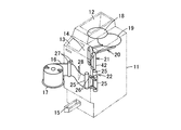
- a hopper 12 for inserting coins to be processed As shown in FIG. 8, a hopper 12 for inserting coins to be processed, a display unit 13 for displaying a selected denomination and various setting items, a denomination and various setting items, etc.
- An operation unit 14 is provided for performing an input operation.
- a wrapping coin dispensing unit 15 for dispensing wrapping coins to the outside is disposed at the front of the machine body 11.
- a wrapping paper supply base 17 On the side of the machine body 11, a wrapping paper supply base 17 is provided for supplying a roll-like wrapping paper 16 for wrapping coins into the machine body 11.
- a supply disk 18 for supplying coins to the lower side of the hopper 12, a feeding disk 19 for feeding coins supplied from the feeding disk 18 one by one, and a coin for feeding one by one from the feeding disk 19
- a stacking unit 21 for stacking coins transported to the end of the transporting unit 20 by a predetermined number of packaging units, and a stacking unit for stacking a predetermined number of packaging units below the stacking unit 21
- a wrapping section 22 for wrapping coins with wrapping paper 16 and creating wrapping coins is provided.
- the wrapping section 22 includes three wrapping rollers 25.
- the stacked coins 16 stacked in the stacking section 21 are arranged between the wrapping rollers 25, sandwiched and rotated, and the wrapping paper 16 having a predetermined length is stacked. Wrapping around the circumferential surface of the stacked coins, the upper and lower ends of the wrapping paper 16 are wound around the upper and lower end surfaces of the stacked coins with a pair of upper and lower winding needles 26, and wrapping coins are created. The created wrapping coin is discharged downward and thrown out to the wrapping coin dispensing unit 15.
- a paper feed roller 27 for feeding the wrapping paper 16 and a cutter 28 for cutting the wrapping paper 16 into a predetermined length are provided.
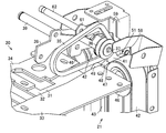
- the transport unit 20 has a transport path 31 for transporting coins (indicated by reference character C in FIGS. 1 and 2) in a single row state. is doing.
- the conveyance path 31 is formed on the passage bottom plate 32 between passage side plates 33 and 34 disposed on both sides of the passage bottom plate 32 so as to be movable in the passage width direction.
- the upper portion of the stacked portion 21 is disposed at the end of the transport path 31 on the downstream side in the transport direction.
- the positions of the passage side plates 33 and 34 are adjusted so as to change the passage width according to the setting of denominations to be packaged.
- a transport belt 35 that transports the coins in the transport path 31 toward the stacking portion 21 on the downstream side in the transport direction is disposed.
- a conveyance belt (not shown) is also disposed on the upstream side in the conveyance direction.
- the conveyor belt 35 is an endless belt having a flat outer peripheral surface and is wound around a plurality of pulleys (only the pulley 36 on the downstream side in the conveyance direction) rotatably supported above the passage bottom plate 32. Has been.
- the pulley 36 on the downstream side in the transport direction is disposed above the stacking portion 21.
- the pulley 36 is rotatably supported by a shaft 37.
- the shaft 37 is attached to an end portion of a support plate 38.
- the support plate 38 is supported by a support shaft 39 so as to be swingable. Not attached to the frame side. Accordingly, the pulley 36 is supported so as to be swingable in the vertical direction with the support shaft 39 as a fulcrum.
- an identification unit for identifying coins to be transported, a stopper for stopping coins following a predetermined number of packaging unit coins stacked in the stacking unit 21, and a packaging denomination A discharge port for removing coins having a smaller diameter is provided.
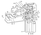
- the stacking unit 21 has a stacking space 41 for receiving coins transported by the transporting unit 20 from above and stacking a predetermined number of packaging units.
- a pair of stacking belts 42 are disposed on both sides of the stacking space 41 corresponding to the direction orthogonal to the transporting direction of coins from the transporting unit 20, respectively.
- the first guide 43 and the second guide 44 are respectively arranged on both sides of the stacking space 41 corresponding to the transport direction.
- the first guide 43 is disposed on the transport unit 20 side, and the second guide 44 is disposed on the opposite side of the transport unit 20. Therefore, a stacking space 41 is formed between the pair of stacking belts 42 and the first guide 43 and the second guide 44.
- the pair of stacked belts 42 are respectively stretched between the upper and lower pulleys 46, and the belt surfaces are opposed to each other with a gap slightly wider than the diameter of the coins to be wrapped.
- Stack support portions 47 are respectively attached to the surfaces of the pair of stack belts 42.
- On the upper surface of the stacking support portion 47 a stacking support surface 48 for supporting coins is formed.
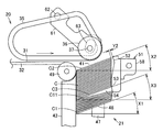
- the stacking support surface 48 is formed on an inclined surface in which the first guide 43 side descends and the second guide 44 side rises so as to incline downward at a predetermined inclination angle X1 toward the transport unit 20 side. Yes.
- the lowest coins stacked in the stacking space 41 are placed in a straddled state, and the first guide 43 side is under the inclination of the coins, Coins are stacked in an inclined state so that the second guide 44 side is above the inclination of the coins.
- the pair of stacked belts 42 are rotated in conjunction with each other so that the opposed surfaces of the pair of stacked belts 42 are directed in the same direction by driving a motor (not shown).
- a motor not shown
- the stacking support portions 47 of the pair of stacking belts 42 are moved one by one by driving the motor.
- coins for a predetermined number of packaging units can be stacked in the stacking space 41.
- the first guide 43 is formed of a plate or the like that is vertically long along the stacking space 41.
- a guide roller 49 for guiding coins fed from the transport unit 20 to the upper portion of the stacking space 41 is rotatably disposed.
- the second guide 44 is formed long along the stacking space 41 in the vertical direction.
- a stopper body 51 is disposed above the second guide 44. The upper portion of the stopper body 51 is disposed above the stacking space 41, and the lower portion of the stopper body 51 is disposed in the stacking space 41.
- the upper part of the stopper body 51 is opposed to the end of the transport unit 20 above the stack space 41 of the stack unit 21, and prevents the coins transported by the transport unit 20 from popping out and dropped into the stack space 41.
- a stopper 52 is formed. The stopper 52 is inclined so that the upper side approaches the center side of the stacking space 41 and the lower side is separated from the stacking space 41 in the outer diameter direction.
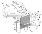
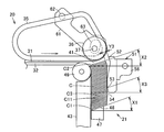
- an inclination maintaining portion 53 is formed extending downward from the stopper 52 integrally.
- This inclination maintaining part 53 is supported by the stacking support part 47 and is located at the height position in the middle of the stacking of coins stacked in the stacking space 41.
- the inclination of the hooked coin (C3) is set to a predetermined inclination angle X3, and the inclination angle X2 of the coin (C2) stacked on the top is maintained substantially equal to the inclination angle X3.
- a space 54 is formed between the side on which the inclination of the coin (C11) is upward and the side on which the inclination of the coin (C3) whose inclination is maintained by the inclination maintaining part 53 is upward.
- the space portion 54 in the middle of the stacking of coins is formed between the coin (C3) that is hooked on the tilt maintaining portion 53 and the coin (C11) that is unhooked. Therefore, the inclination maintaining unit 53 maintains the inclination of the coins (C3 to C2) above the space part 54 in the middle of coins.
- the inclination maintaining part 53 is caught on the upper side of the coin, but the hook is released downward by lowering the side on which the coin is inclined as the stacking support part 47 is lowered.
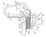
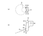
- the inclination maintaining part 53 has a recessed part 55 into which the side on which the inclination of the coin enters is formed on the surface of the inclination maintaining part 53 facing the stacking space 41.
- the both side edges of the depression 55 are gradually projected into the stacking space 41 from above so that the side on which the slope of the coin comes in contact is hooked, and the width dimension (diameter dimension) of the stacking space 41 is narrowed.
- An inclined contact portion 56 is formed, and an inclination maintaining contact portion 57 for maintaining the inclination of the coin at a predetermined inclination angle X3 is formed below the inclined contact portion 56. It is configured to be caught.
- the recessed portion 55 has a larger amount entering smaller coins, and a smaller amount entering larger recesses.
- an attachment portion 58 that is attached to an adjustment mechanism (not shown) that supports the stopper body 51 is formed.
- the pair of stacked belts 42, the first guide 43, the second guide 44, the stopper body 51, and the like can be adjusted to move to positions corresponding to the denominations to be packaged by an adjusting mechanism (not shown). It is supported. With this adjustment mechanism, the opposing distance between the pair of stacked belts 42 is adjusted around the central axis of the stacked space 41, and the stacking in the direction orthogonal to the opposing direction of the pair of stacked belts 42 is performed. The positions of the belt 42, the first guide 43, the second guide 44, and the stopper body 51 are adjusted.
- a plurality of fixed stoppers 59 are disposed above both sides of the stopper body 51 so that the tip faces the pulley 36 and the conveyor belt 35 and the stopper 52. This fixed stopper 59 prevents the coins that have been transported by the transport unit 20 from colliding with the stopper 52.
- a detection lever 61 is disposed on the side of the pulley 36 of the conveyor belt 35 for detecting clogging of coins in the stacked portion 21 or for correcting the upper surface position of stacked coins in the stacked portion 21. .
- the base end of the detection lever 61 is swingably supported by a support shaft 62 attached to a frame (not shown) at an upper position upstream of the transport unit 20 in the transport direction from the position of the stacking unit 21.
- the front end side of the detection lever 61 is disposed above the stacking portion 21 at the side position of the pulley 36 of the transport belt 35. Accordingly, the detection lever 61 is disposed obliquely along the transport direction of the transport unit 20 from the proximal end to the distal end side. Further, a hole 63 that avoids interference with the shaft 37 of the pulley 36 is formed on the distal end side of the detection lever 61. Therefore, the pulley 36 and the detection lever 61 can swing independently.
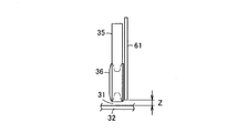
- the lowering position of the tip of the detection lever 61 is a position spaced from the upper surface of the passage bottom plate 32 of the conveyance path 31 by a predetermined distance Z and above the peripheral surfaces of the pulley 36 and the conveyance belt 35. It is regulated by the position.
- the interval Z is such that coins that are normally received from the transport unit 20 into the stacking unit 21 and coins that have bounced slightly do not touch or push up the detection lever 61, and the stacking unit 21 is clogged. It is set to a size that allows the detection lever 61 to be pushed up by a coin or a coin received in the stacking unit 21 from the transport unit 20 because the space above the uppermost coin of the stacking unit 21 is reduced.
- the detection lever 61 has a position where the lowering is restricted as a fixed position. From this fixed position, the detection lever 61 can swing upward with the support shaft 62 as a fulcrum, and is directed toward the fixed position by a biasing means such as a spring (not shown). It is energized.
- Detecting unit such as a switch or a sensor (not shown) that detects that the detecting lever 61 has swung upward from a fixed position.
- the transport unit 20, the stacking unit 21, and the packaging unit 22 are automatically adjusted in accordance with the set denomination. That is, in the transport unit 20, the passage width between the passage side plates 33 and 34 is adjusted. In the stacking portion 21, the facing distance between the pair of stacking belts 42 is adjusted, and the stacking belt 42, the first guide 43, the first guide 43 in the direction orthogonal to the direction in which the pair of stacking belts 42 face each other is adjusted. The positions of the second guide 44 and the stopper body 51 are adjusted. In the packaging unit 22, the interval between the packaging rollers 25, the position of the winding needle 26, and the like are adjusted.
- Coins put into the hopper 12 of the coin wrapping machine are fed from the supply disk 18 to the feeding disk 19, and the coins are fed from the feeding disk 19 one by one to the transport unit 20.
- the coins fed out from the feeding disk 19 are received between the passage side plates 33 and 34 on both sides of the passage bottom plate 32 of the conveyance path 31, and are arranged on the conveyance belt disposed on the upstream side in the conveyance direction and on the downstream side in the conveyance direction. It is conveyed downstream in the conveying direction by the arranged conveying belt 35.
- the identification unit identifies and counts.
- Coins transported to the end of the transport unit 20 are discharged above the stacking unit 21.
- the coins released from the transport unit 20 above the stacking unit 21 are slidably contacted with the stacking support surface 48 of the stacking support unit 47 by the force from the top of the transporting unit 20, and the second sheet After that, it contacts the stopper 52 while sliding the upper surface of the stacked coins, falls into the stacked space 41 of the stacked portion 21 without jumping out from the stacked portion 21, and the height of the transport path 31 of the transport unit 20 in advance. It is placed on the stacking support surface 48 of the stacking support portion 47 that has been arranged nearby.
- the coins placed on the stacking support surface 48 are tilted downward toward the transport unit 20 due to the tilting of the stacking support surface 48, and are in a state of being biased to the guide roller 49 and the first guide 43.
- the stacking support part 47 is lowered by one coin, and the uppermost part stacked on the stacking support part 47. Make a space to stack the next coin on the coin.
- the coins sequentially conveyed from the conveying unit 20 are sequentially stacked on the stacked coins on the stacking support unit 47.
- the conveyor belt 35 is extended to the upper side of the stacking portion 21 by the pulley 36, the stacking support surface 48 of the stacking support portion 47 or the upper surface of the stacked coins is close to the height of the transporting path 20. That the stacking support surface 48 or the upper surface of the stacked coins is inclined downward toward the transport unit 20, and the detection lever 61 is positioned above the peripheral surface of the transport belt 35. By not contacting the normally stacked coins, the coins transported from the transport unit 20 to the stack unit 21 can be smoothly stacked in the stack space 41.
- the coin is tilted at a height position in the middle of stacking of the coins supported by the stacking support part 47 and stacked in the stacking space 41.
- the side on which the top becomes contacted with the inclination maintaining portion 53 and is caught. Even if the side on which the inclination of the coin is increased is caught by the inclination maintaining portion 53, the side on which the inclination of the coin is lowered is lowered by the lowering of the stacking support portion 47, so that the catch is released and the coin is lowered.
- the inclination of the hooked coin (C3) is set to a predetermined inclination angle X3, and the coin (C3) is stacked on the hooked coin (C3).
- the inclination angle X2 of the uppermost coin (C2) is maintained substantially equal to the inclination angle X3.
- the coin (C1) that is supported and stacked on the stacking support surface 48 of the stacking support section 47 below the tilt maintaining section 53, the patterns of coins that overlap each other are caught or stacked. Since there is some margin in the horizontal direction in 21, even if it is tilted, the coins may be shifted and stacked in the horizontal direction, and as the number of stacked coins increases, the coin (C11) may gradually become horizontal. .
- the coin (C11) that is supported by the stacking support surface 48 of the stacking support part 47 and that is near horizontal is inclined upward, and the coin ( C3) between the side where the inclination is on the upper side, that is, between the coin (C11) that is caught off the inclination maintaining part 53 and the coin (C3) that is caught on the inclination maintaining part 53, the space part 54 Is formed.
- the inclination maintaining part 53 maintains the inclination of the coins (C3 to C2) above the space part 54 in the middle of coin stacking.
- the inclination maintaining part 53 is a coin above the space part 54 in the middle of stacking so that the space part 54 is formed on the side where the inclination of the coins is in the middle of the stacking, Since the uppermost coin (C2) can be forcibly maintained in inclination, the coins received in the stacking unit 21 from the transport unit 20 are tilted by the force from the top of the transport unit 20 It can be slid into contact with the surface, and the coins can be stacked without any disturbance by forcibly pressing downward, so that the coins can be surely aligned.
- the inclination maintaining unit 53 extends integrally from the stopper 52 that prevents the coins conveyed by the conveying unit 20 from popping out, and at the height position in the middle of the stacking of the coins stacked in the stacking space 41. Since the stacked space is provided to have a narrow width, the number of parts can be reduced, and the inclination maintaining unit 53 only needs to hold a part of the stacked coins, and the weight burden on the inclination maintaining unit 53 can be reduced.
- the denomination to be wrapped is a large-diameter coin
- the coins caught on both side edges of the recessed portion 55 of the tilt maintaining portion 53 are maintained at a predetermined tilt angle X3.
- the amount of the coin peripheral edge entering the recess 55 of the inclination maintaining portion 53 is small, and the interval between the coin stacked on the top of the stacking space 41 and the stopper 52 is Y1.
- the effect of providing the depression 55 in the inclination maintaining portion 53 is compared with that of the inclination maintaining portion 53 in which the depression 55 is not provided as in the second embodiment shown in FIGS. 9 and 10. I will explain.
- the denomination to be wrapped is a large-diameter coin
- the coin caught on the inclination maintaining part 53 is stacked on the uppermost part of the stacking space 41 while maintaining the predetermined inclination angle X3.
- the interval between the inserted coin and the stopper 52 is Y2.
- the coin hooked on the inclination maintaining part 53 is maintained at a predetermined inclination angle X3 and is stacked on the uppermost part of the stacking space 41.
- the interval Y3 between the stacked coins and the stopper 52 is larger than the interval Y2 in the case of large-diameter coins.
- the inclination maintaining portion 53 in a shape having the recessed portion 55 into which the side on which the inclination of the coin enters is increased, the smaller diameter coin enters the inclination maintaining portion 53 and is stacked on the uppermost portion of the stacking space 41.
- the distance between the coins and the stopper 52 can be reduced, so that the distance between the coins stacked on the top of the stacking space 41 and the stopper 52 can be made substantially constant regardless of the diameter of the coins. And coins can be stacked stably.
- the subsequent coins are stopped with a stopper, and the coins for the predetermined number of packaging units are stacked on the stacking unit 21. .
- the stopper body 51 After completing the stacking of the number of coins in the stacking portion 21, the stopper body 51 is moved in the outer diameter direction away from the stacking space 41, and then the stacking support portion 47 is lowered to stack the stacked coins. Is lowered and delivered to the packaging unit 22 side.
- the wrapping section 22 receives the stacked coins from the stacking section 21, and places the stacked coins between the wrapping rollers 25, sandwiches and rotates the wrapping paper 16 with a predetermined length around the circumferential surface of the stacked coins.
- the upper and lower ends of the wrapping paper 16 are wound around the upper and lower end surfaces of the stacked coins and caulked with a pair of upper and lower winding needles 26 to create a wrapping coin.
- the detection lever 61 when used for detecting the clogging of coins in the stacked portion 21, the clogging of the coins occurs in the stacked portion 21, and the detection lever 61 is pushed up by the packed coins. By detecting that the detection lever 61 is pushed up, the operation is stopped and the clogging of coins can be eliminated.
- the detection lever 61 when the detection lever 61 is used for correcting the upper surface position of the stacked coins in the stacking portion 21, the uppermost coin is caused by the variation in the stack height of the coins stacked on the stacking portion 21. The space above is reduced, and the detection lever 61 is pushed up by the coins received from the transport unit 20 into the stacking unit 21. By detecting that the detection lever 61 is pushed up, the stacking support portion 47 is lowered by a predetermined amount, the space above the uppermost coin can be widened, and the space can be appropriately maintained.
- a conveyance belt of a conveyance section that conveys coins is extended to above the stacking section, and this conveyance belt is supported so as to be vertically movable.
- a detection unit that detects that the button is pushed upward.
- the detection unit detects that the conveyor belt has been pushed upward when a coin that is stacked on the stacking part is bitten or a coin that is thicker than a denomination coin to be packed enters the stacking part. To detect that a stacking defect has occurred.
- the conveyor belt since the conveying part and the stacking failure detection part are the same part, the conveyor belt may be pushed up due to the bounce of coins generated when the coins are stacked. Therefore, there is a problem that the operation is frequently stopped during the stacking process.
- the conveyance belt 35 and the detection lever 61 of the conveyance unit 20 are provided separately, and the lowering position of the detection lever 61 is positioned higher than the upper surface of the conveyance path 31 of the conveyance unit 20, Even if some bounces are not transmitted directly to the detection lever 61, the occurrence of false detection can be reduced.
- FIG. 9 and FIG. 10 show a second embodiment.
- the depression 55 of the inclination maintaining part 53 is provided.
- an example of the inclination maintaining part 53 without the depression 55 is shown.
- this inclination maintaining part 53 if the accumulation of coins is continued in the accumulation part 21, the height in the middle of the accumulation of coins supported by the accumulation support part 47 and accumulated in the accumulation space 41 At the position, the side on which the coin is inclined comes into contact with the inclination maintaining portion 53 and is caught. Even if the side on which the inclination of the coin is increased is caught by the inclination maintaining portion 53, the side on which the inclination of the coin is lowered is lowered by the lowering of the stacking support portion 47, so that the catch is released and the coin is lowered.
- the tilt of the hooked coin is set to a predetermined tilt angle X3, and the tilt angle of the uppermost coin stacked on the hooked coin is tilted Maintain X2 approximately equal to the tilt angle X3.
- the inclination of the coins supported by the stacking support surface 48 of the stacking support portion 47 is increased.
- a space 54 is formed between the side where the inclination is maintained and the side where the inclination of the coin whose inclination is maintained by the inclination maintaining part 53 is on the upper side. In this state, the inclination maintaining part 53 maintains the inclination of the coins above the space part 54 in the middle of coin stacking.
- the space portion 54 in the middle of the coin stacking is formed between the coin hooked on the tilt maintaining portion 53 and the coin that is unhooked. Is done.
- the space portion 54 in the middle of the coin stacking is a little lower coin that overlaps with the coin caught on the inclination maintaining portion 53.
- it is formed slightly below the coins caught on the inclination maintaining part 53.
- it may be formed between the coin that is hooked on the inclination maintaining portion 53 and the coin that is unhooked, similarly to the large-diameter coin.
- 54 is formed so that it is a coin above the space part 54 in the middle of its stacking, and in particular, the inclination of the uppermost coin can be forcibly maintained.
- the coins received in can be surely put together and the coins can be piled up without any disturbance.
- a protrusion, a rotatable roller, etc. may be sufficient, for example.
- the present invention is used for a coin processing machine having only a function of packaging coins, a coin wrapping machine having a function of counting loose coins, and a function of storing and dispensing packed wrapping coins.
Landscapes
- Engineering & Computer Science (AREA)
- Mechanical Engineering (AREA)
- Physics & Mathematics (AREA)
- General Physics & Mathematics (AREA)
- Basic Packing Technique (AREA)
Abstract
Description
21 重積部
22 包装部
41 重積空間
47 重積支持部
48 重積支持面
52 ストッパ
53 傾斜維持部
54 空間部
55 窪み部
C 硬貨
Claims (4)
- 硬貨を1枚ずつ搬送する搬送部と、
この搬送部で搬送してきた硬貨を上方から受け入れて所定枚数重積する重積空間を設けた重積部と、
上面に傾斜した重積支持面が設けられ、この重積支持面で前記重積空間に重積する硬貨を傾斜状態に支え、硬貨を重積する毎に下降する重積支持部と、
この重積支持部に支えられて前記重積空間に重積される硬貨の重積途中で、硬貨の傾斜が上になる側に空間部が形成されるように、その重積途中の空間部より上側の硬貨の傾斜を維持する傾斜維持部と、
前記重積部で所定枚数重積された硬貨を包装する包装部と
を具備していることを特徴とする硬貨包装機。 - 前記傾斜維持部は、前記重積支持部に支えられて前記重積空間に重積される硬貨の重積途中の高さ位置で、硬貨の傾斜が上になる側が接触して引っ掛かるとともに、その硬貨の引っ掛かりは前記重積支持部の下降に伴って硬貨の傾斜が下になる側が下降することで外れるのを許容する
ことを特徴とする請求項1記載の硬貨包装機。 - 前記重積部の重積空間の上方で前記搬送部と相対する位置に設けられ、前記搬送部で搬送してきた硬貨の飛び出しを阻止するストッパを具備し、
前記傾斜維持部は、前記ストッパから前記重積空間に延設され、前記重積空間に重積される硬貨の重積途中の高さ位置で前記重積空間の幅寸法を狭くした
ことを特徴とする請求項1記載の硬貨包装機。 - 前記傾斜維持部には、硬貨の傾斜が上になる側が入り込む窪み部が設けられている
ことを特徴とする請求項3記載の硬貨包装機。
Priority Applications (4)
| Application Number | Priority Date | Filing Date | Title |
|---|---|---|---|
| US12/737,889 US8955295B2 (en) | 2008-09-04 | 2008-09-04 | Coin wrapping machine |
| PCT/JP2008/065949 WO2010026635A1 (ja) | 2008-09-04 | 2008-09-04 | 硬貨包装機 |
| JP2010527620A JP5216860B2 (ja) | 2008-09-04 | 2008-09-04 | 硬貨包装機 |
| EP08810004.5A EP2325088B1 (en) | 2008-09-04 | 2008-09-04 | Coin wrapping machine |
Applications Claiming Priority (1)
| Application Number | Priority Date | Filing Date | Title |
|---|---|---|---|
| PCT/JP2008/065949 WO2010026635A1 (ja) | 2008-09-04 | 2008-09-04 | 硬貨包装機 |
Publications (1)
| Publication Number | Publication Date |
|---|---|
| WO2010026635A1 true WO2010026635A1 (ja) | 2010-03-11 |
Family
ID=41796823
Family Applications (1)
| Application Number | Title | Priority Date | Filing Date |
|---|---|---|---|
| PCT/JP2008/065949 Ceased WO2010026635A1 (ja) | 2008-09-04 | 2008-09-04 | 硬貨包装機 |
Country Status (4)
| Country | Link |
|---|---|
| US (1) | US8955295B2 (ja) |
| EP (1) | EP2325088B1 (ja) |
| JP (1) | JP5216860B2 (ja) |
| WO (1) | WO2010026635A1 (ja) |
Cited By (2)
| Publication number | Priority date | Publication date | Assignee | Title |
|---|---|---|---|---|
| US9457922B2 (en) | 2012-08-24 | 2016-10-04 | Kraft Foods Group Brands Llc | Food product orienting and loading apparatus |
| CN109016640A (zh) * | 2018-09-10 | 2018-12-18 | 佛山市三水至丰纸品制造有限公司 | 一种瓦楞纸箱折叠钉箱堆叠一体机 |
Citations (4)
| Publication number | Priority date | Publication date | Assignee | Title |
|---|---|---|---|---|
| JPH0290211U (ja) * | 1988-12-28 | 1990-07-17 | ||
| JPH072224A (ja) * | 1993-06-16 | 1995-01-06 | Laurel Bank Mach Co Ltd | 硬貨集積装置 |
| JPH11175790A (ja) * | 1997-12-05 | 1999-07-02 | Laurel Bank Mach Co Ltd | 硬貨集積装置 |
| JP2971698B2 (ja) | 1993-05-20 | 1999-11-08 | ローレルバンクマシン株式会社 | 硬貨集積装置 |
Family Cites Families (19)
| Publication number | Priority date | Publication date | Assignee | Title |
|---|---|---|---|---|
| US2523089A (en) * | 1947-10-22 | 1950-09-19 | David I Block | Coin stacking and packaging device |
| US3265077A (en) * | 1965-06-03 | 1966-08-09 | Kirkpatrick Donald | Coin stacking and handling device |
| DE1940389A1 (de) * | 1969-08-08 | 1971-02-18 | Reis Standardwerk | Vorrichtung zur Muenzen-UEberfuehrung an Muenzgeld-Verpackungsmaschinen |
| CH528431A (de) * | 1970-08-03 | 1972-09-30 | Sig Schweiz Industrieges | Stapeleinrichtung für regelmässig geformte, flache Gegenstände, z.B. Biskuits |
| US3882659A (en) * | 1973-07-16 | 1975-05-13 | Herbert Charlop | Coin counting and packing device |
| US3967435A (en) * | 1974-09-13 | 1976-07-06 | Bergmaier Gerard J | Coin-stacking and counting device |
| JPS5832086B2 (ja) * | 1975-10-18 | 1983-07-11 | グローリー工業株式会社 | コウカホウソウキノジユウセキコウカシジソウチ |
| US4089151A (en) * | 1977-05-11 | 1978-05-16 | Brandt, Inc. | Coin wrapping machine |
| JPS55166706U (ja) * | 1979-05-17 | 1980-12-01 | ||
| JPS5873522A (ja) * | 1981-10-28 | 1983-05-02 | グローリー工業株式会社 | 硬貨包装機等における硬貨累積装置 |
| US4674260A (en) * | 1985-09-20 | 1987-06-23 | Cummins-Allison Corporation | Coin wrapping mechanism |
| JPH052409Y2 (ja) * | 1986-02-28 | 1993-01-21 | ||
| JPS62208329A (ja) * | 1986-02-28 | 1987-09-12 | ロ−レルバンクマシン株式会社 | 硬貨集積装置 |
| JPH085452B2 (ja) * | 1986-12-26 | 1996-01-24 | グローリー工業株式会社 | 硬貨包装機 |
| JPH0669804B2 (ja) * | 1987-11-13 | 1994-09-07 | 武蔵エンジニアリング株式会社 | 硬貨包装装置 |
| JPH0290211A (ja) | 1988-09-27 | 1990-03-29 | Toshiba Corp | 無人搬送車制御装置 |
| US5389034A (en) * | 1993-07-21 | 1995-02-14 | Standardwerk Eugen Reis Gmbh | Device for stacking coins or similar disk-shaped objects |
| US7470175B2 (en) * | 2000-07-07 | 2008-12-30 | Glory Kogyo Kabushiki Kaisha | Coin stacking apparatus |
| JP2002019964A (ja) * | 2000-07-07 | 2002-01-23 | Glory Ltd | 硬貨重積装置 |
-
2008
- 2008-09-04 EP EP08810004.5A patent/EP2325088B1/en not_active Not-in-force
- 2008-09-04 WO PCT/JP2008/065949 patent/WO2010026635A1/ja not_active Ceased
- 2008-09-04 US US12/737,889 patent/US8955295B2/en active Active
- 2008-09-04 JP JP2010527620A patent/JP5216860B2/ja not_active Expired - Fee Related
Patent Citations (4)
| Publication number | Priority date | Publication date | Assignee | Title |
|---|---|---|---|---|
| JPH0290211U (ja) * | 1988-12-28 | 1990-07-17 | ||
| JP2971698B2 (ja) | 1993-05-20 | 1999-11-08 | ローレルバンクマシン株式会社 | 硬貨集積装置 |
| JPH072224A (ja) * | 1993-06-16 | 1995-01-06 | Laurel Bank Mach Co Ltd | 硬貨集積装置 |
| JPH11175790A (ja) * | 1997-12-05 | 1999-07-02 | Laurel Bank Mach Co Ltd | 硬貨集積装置 |
Non-Patent Citations (1)
| Title |
|---|
| See also references of EP2325088A4 * |
Cited By (2)
| Publication number | Priority date | Publication date | Assignee | Title |
|---|---|---|---|---|
| US9457922B2 (en) | 2012-08-24 | 2016-10-04 | Kraft Foods Group Brands Llc | Food product orienting and loading apparatus |
| CN109016640A (zh) * | 2018-09-10 | 2018-12-18 | 佛山市三水至丰纸品制造有限公司 | 一种瓦楞纸箱折叠钉箱堆叠一体机 |
Also Published As
| Publication number | Publication date |
|---|---|
| EP2325088A4 (en) | 2012-07-25 |
| EP2325088B1 (en) | 2017-03-29 |
| EP2325088A1 (en) | 2011-05-25 |
| US8955295B2 (en) | 2015-02-17 |
| US20110154786A1 (en) | 2011-06-30 |
| JP5216860B2 (ja) | 2013-06-19 |
| JPWO2010026635A1 (ja) | 2012-01-26 |
Similar Documents
| Publication | Publication Date | Title |
|---|---|---|
| US20070278736A1 (en) | Bill Processor | |
| JP4899084B2 (ja) | 硬貨処理装置の硬貨受入装置 | |
| JPWO2009118853A1 (ja) | 硬貨包装機 | |
| JP5216860B2 (ja) | 硬貨包装機 | |
| US20190300311A1 (en) | Paper sheet handling apparatus and method for detecting foreign object | |
| CN105857676A (zh) | 硬币包装机、硬币包装系统以及硬币包装方法 | |
| JP2007141062A (ja) | 紙葉類処理装置 | |
| JP2011154654A (ja) | 紙葉類処理装置 | |
| JP2010061510A (ja) | 棒金収納装置 | |
| JP5144765B2 (ja) | 硬貨重積装置 | |
| JP7725033B2 (ja) | 硬貨処理機 | |
| JP4528078B2 (ja) | 硬貨包装装置 | |
| JP4528081B2 (ja) | 包装硬貨受渡装置 | |
| JP5619503B2 (ja) | 硬貨包装装置 | |
| JP3397961B2 (ja) | 硬貨包装機 | |
| JP2002279481A (ja) | 硬貨包装装置 | |
| JP2000007232A (ja) | 紙葉類収納繰出し装置 | |
| JP5094961B2 (ja) | 硬貨処理機 | |
| JP3996748B2 (ja) | 包装硬貨の整列供給装置 | |
| JP2008087941A (ja) | シート製品の供給装置およびシート製品の供給方法 | |
| JP6596540B1 (ja) | 紙葉類処理装置 | |
| JP2516344Y2 (ja) | 硬貨包装収納投出機 | |
| JP2001080748A (ja) | 紙幣収納繰出し装置 | |
| JP2023050372A (ja) | 硬貨集積機構及び硬貨包装機 | |
| HK1113846B (en) | Bill processor |
Legal Events
| Date | Code | Title | Description |
|---|---|---|---|
| 121 | Ep: the epo has been informed by wipo that ep was designated in this application |
Ref document number: 08810004 Country of ref document: EP Kind code of ref document: A1 |
|
| WWE | Wipo information: entry into national phase |
Ref document number: 2010527620 Country of ref document: JP |
|
| WWE | Wipo information: entry into national phase |
Ref document number: 12737889 Country of ref document: US |
|
| NENP | Non-entry into the national phase |
Ref country code: DE |
|
| REEP | Request for entry into the european phase |
Ref document number: 2008810004 Country of ref document: EP |
|
| WWE | Wipo information: entry into national phase |
Ref document number: 2008810004 Country of ref document: EP |