WO2010026864A1 - 排気ガス処理装置 - Google Patents
排気ガス処理装置 Download PDFInfo
- Publication number
- WO2010026864A1 WO2010026864A1 PCT/JP2009/064358 JP2009064358W WO2010026864A1 WO 2010026864 A1 WO2010026864 A1 WO 2010026864A1 JP 2009064358 W JP2009064358 W JP 2009064358W WO 2010026864 A1 WO2010026864 A1 WO 2010026864A1
- Authority
- WO
- WIPO (PCT)
- Prior art keywords
- cylinder
- upstream
- downstream
- exhaust gas
- flange portion
- Prior art date
- Legal status (The legal status is an assumption and is not a legal conclusion. Google has not performed a legal analysis and makes no representation as to the accuracy of the status listed.)
- Ceased
Links
Images





Classifications
-
- F—MECHANICAL ENGINEERING; LIGHTING; HEATING; WEAPONS; BLASTING
- F01—MACHINES OR ENGINES IN GENERAL; ENGINE PLANTS IN GENERAL; STEAM ENGINES
- F01N—GAS-FLOW SILENCERS OR EXHAUST APPARATUS FOR MACHINES OR ENGINES IN GENERAL; GAS-FLOW SILENCERS OR EXHAUST APPARATUS FOR INTERNAL-COMBUSTION ENGINES
- F01N3/00—Exhaust or silencing apparatus having means for purifying, rendering innocuous, or otherwise treating exhaust
- F01N3/02—Exhaust or silencing apparatus having means for purifying, rendering innocuous, or otherwise treating exhaust for cooling, or for removing solid constituents of, exhaust
-
- F—MECHANICAL ENGINEERING; LIGHTING; HEATING; WEAPONS; BLASTING
- F01—MACHINES OR ENGINES IN GENERAL; ENGINE PLANTS IN GENERAL; STEAM ENGINES
- F01N—GAS-FLOW SILENCERS OR EXHAUST APPARATUS FOR MACHINES OR ENGINES IN GENERAL; GAS-FLOW SILENCERS OR EXHAUST APPARATUS FOR INTERNAL-COMBUSTION ENGINES
- F01N3/00—Exhaust or silencing apparatus having means for purifying, rendering innocuous, or otherwise treating exhaust
- F01N3/02—Exhaust or silencing apparatus having means for purifying, rendering innocuous, or otherwise treating exhaust for cooling, or for removing solid constituents of, exhaust
- F01N3/021—Exhaust or silencing apparatus having means for purifying, rendering innocuous, or otherwise treating exhaust for cooling, or for removing solid constituents of, exhaust by means of filters
- F01N3/033—Exhaust or silencing apparatus having means for purifying, rendering innocuous, or otherwise treating exhaust for cooling, or for removing solid constituents of, exhaust by means of filters in combination with other devices
- F01N3/0335—Exhaust or silencing apparatus having means for purifying, rendering innocuous, or otherwise treating exhaust for cooling, or for removing solid constituents of, exhaust by means of filters in combination with other devices with exhaust silencers in a single housing
-
- F—MECHANICAL ENGINEERING; LIGHTING; HEATING; WEAPONS; BLASTING
- F01—MACHINES OR ENGINES IN GENERAL; ENGINE PLANTS IN GENERAL; STEAM ENGINES
- F01N—GAS-FLOW SILENCERS OR EXHAUST APPARATUS FOR MACHINES OR ENGINES IN GENERAL; GAS-FLOW SILENCERS OR EXHAUST APPARATUS FOR INTERNAL-COMBUSTION ENGINES
- F01N1/00—Silencing apparatus characterised by method of silencing
- F01N1/02—Silencing apparatus characterised by method of silencing by using resonance
-
- F—MECHANICAL ENGINEERING; LIGHTING; HEATING; WEAPONS; BLASTING
- F01—MACHINES OR ENGINES IN GENERAL; ENGINE PLANTS IN GENERAL; STEAM ENGINES
- F01N—GAS-FLOW SILENCERS OR EXHAUST APPARATUS FOR MACHINES OR ENGINES IN GENERAL; GAS-FLOW SILENCERS OR EXHAUST APPARATUS FOR INTERNAL-COMBUSTION ENGINES
- F01N13/00—Exhaust or silencing apparatus characterised by constructional features
- F01N13/009—Exhaust or silencing apparatus characterised by constructional features having two or more separate purifying devices arranged in series
-
- F—MECHANICAL ENGINEERING; LIGHTING; HEATING; WEAPONS; BLASTING
- F01—MACHINES OR ENGINES IN GENERAL; ENGINE PLANTS IN GENERAL; STEAM ENGINES
- F01N—GAS-FLOW SILENCERS OR EXHAUST APPARATUS FOR MACHINES OR ENGINES IN GENERAL; GAS-FLOW SILENCERS OR EXHAUST APPARATUS FOR INTERNAL-COMBUSTION ENGINES
- F01N13/00—Exhaust or silencing apparatus characterised by constructional features
- F01N13/009—Exhaust or silencing apparatus characterised by constructional features having two or more separate purifying devices arranged in series
- F01N13/0097—Exhaust or silencing apparatus characterised by constructional features having two or more separate purifying devices arranged in series the purifying devices are arranged in a single housing
-
- F—MECHANICAL ENGINEERING; LIGHTING; HEATING; WEAPONS; BLASTING
- F01—MACHINES OR ENGINES IN GENERAL; ENGINE PLANTS IN GENERAL; STEAM ENGINES
- F01N—GAS-FLOW SILENCERS OR EXHAUST APPARATUS FOR MACHINES OR ENGINES IN GENERAL; GAS-FLOW SILENCERS OR EXHAUST APPARATUS FOR INTERNAL-COMBUSTION ENGINES
- F01N13/00—Exhaust or silencing apparatus characterised by constructional features
- F01N13/08—Other arrangements or adaptations of exhaust conduits
-
- F—MECHANICAL ENGINEERING; LIGHTING; HEATING; WEAPONS; BLASTING
- F01—MACHINES OR ENGINES IN GENERAL; ENGINE PLANTS IN GENERAL; STEAM ENGINES
- F01N—GAS-FLOW SILENCERS OR EXHAUST APPARATUS FOR MACHINES OR ENGINES IN GENERAL; GAS-FLOW SILENCERS OR EXHAUST APPARATUS FOR INTERNAL-COMBUSTION ENGINES
- F01N13/00—Exhaust or silencing apparatus characterised by constructional features
- F01N13/18—Construction facilitating manufacture, assembly, or disassembly
- F01N13/1805—Fixing exhaust manifolds, exhaust pipes or pipe sections to each other, to engine or to vehicle body
-
- F—MECHANICAL ENGINEERING; LIGHTING; HEATING; WEAPONS; BLASTING
- F01—MACHINES OR ENGINES IN GENERAL; ENGINE PLANTS IN GENERAL; STEAM ENGINES
- F01N—GAS-FLOW SILENCERS OR EXHAUST APPARATUS FOR MACHINES OR ENGINES IN GENERAL; GAS-FLOW SILENCERS OR EXHAUST APPARATUS FOR INTERNAL-COMBUSTION ENGINES
- F01N13/00—Exhaust or silencing apparatus characterised by constructional features
- F01N13/18—Construction facilitating manufacture, assembly, or disassembly
- F01N13/1805—Fixing exhaust manifolds, exhaust pipes or pipe sections to each other, to engine or to vehicle body
- F01N13/1827—Sealings specially adapted for exhaust systems
-
- F—MECHANICAL ENGINEERING; LIGHTING; HEATING; WEAPONS; BLASTING
- F01—MACHINES OR ENGINES IN GENERAL; ENGINE PLANTS IN GENERAL; STEAM ENGINES
- F01N—GAS-FLOW SILENCERS OR EXHAUST APPARATUS FOR MACHINES OR ENGINES IN GENERAL; GAS-FLOW SILENCERS OR EXHAUST APPARATUS FOR INTERNAL-COMBUSTION ENGINES
- F01N13/00—Exhaust or silencing apparatus characterised by constructional features
- F01N13/18—Construction facilitating manufacture, assembly, or disassembly
- F01N13/1838—Construction facilitating manufacture, assembly, or disassembly characterised by the type of connection between parts of exhaust or silencing apparatus, e.g. between housing and tubes, between tubes and baffles
- F01N13/1844—Mechanical joints
- F01N13/1855—Mechanical joints the connection being realised by using bolts, screws, rivets or the like
-
- F—MECHANICAL ENGINEERING; LIGHTING; HEATING; WEAPONS; BLASTING
- F01—MACHINES OR ENGINES IN GENERAL; ENGINE PLANTS IN GENERAL; STEAM ENGINES
- F01N—GAS-FLOW SILENCERS OR EXHAUST APPARATUS FOR MACHINES OR ENGINES IN GENERAL; GAS-FLOW SILENCERS OR EXHAUST APPARATUS FOR INTERNAL-COMBUSTION ENGINES
- F01N3/00—Exhaust or silencing apparatus having means for purifying, rendering innocuous, or otherwise treating exhaust
- F01N3/08—Exhaust or silencing apparatus having means for purifying, rendering innocuous, or otherwise treating exhaust for rendering innocuous
- F01N3/10—Exhaust or silencing apparatus having means for purifying, rendering innocuous, or otherwise treating exhaust for rendering innocuous by thermal or catalytic conversion of noxious components of exhaust
- F01N3/105—General auxiliary catalysts, e.g. upstream or downstream of the main catalyst
- F01N3/106—Auxiliary oxidation catalysts
-
- F—MECHANICAL ENGINEERING; LIGHTING; HEATING; WEAPONS; BLASTING
- F01—MACHINES OR ENGINES IN GENERAL; ENGINE PLANTS IN GENERAL; STEAM ENGINES
- F01N—GAS-FLOW SILENCERS OR EXHAUST APPARATUS FOR MACHINES OR ENGINES IN GENERAL; GAS-FLOW SILENCERS OR EXHAUST APPARATUS FOR INTERNAL-COMBUSTION ENGINES
- F01N3/00—Exhaust or silencing apparatus having means for purifying, rendering innocuous, or otherwise treating exhaust
- F01N3/08—Exhaust or silencing apparatus having means for purifying, rendering innocuous, or otherwise treating exhaust for rendering innocuous
- F01N3/10—Exhaust or silencing apparatus having means for purifying, rendering innocuous, or otherwise treating exhaust for rendering innocuous by thermal or catalytic conversion of noxious components of exhaust
- F01N3/24—Exhaust or silencing apparatus having means for purifying, rendering innocuous, or otherwise treating exhaust for rendering innocuous by thermal or catalytic conversion of noxious components of exhaust characterised by constructional aspects of converting apparatus
-
- F—MECHANICAL ENGINEERING; LIGHTING; HEATING; WEAPONS; BLASTING
- F01—MACHINES OR ENGINES IN GENERAL; ENGINE PLANTS IN GENERAL; STEAM ENGINES
- F01N—GAS-FLOW SILENCERS OR EXHAUST APPARATUS FOR MACHINES OR ENGINES IN GENERAL; GAS-FLOW SILENCERS OR EXHAUST APPARATUS FOR INTERNAL-COMBUSTION ENGINES
- F01N3/00—Exhaust or silencing apparatus having means for purifying, rendering innocuous, or otherwise treating exhaust
- F01N3/08—Exhaust or silencing apparatus having means for purifying, rendering innocuous, or otherwise treating exhaust for rendering innocuous
- F01N3/10—Exhaust or silencing apparatus having means for purifying, rendering innocuous, or otherwise treating exhaust for rendering innocuous by thermal or catalytic conversion of noxious components of exhaust
- F01N3/24—Exhaust or silencing apparatus having means for purifying, rendering innocuous, or otherwise treating exhaust for rendering innocuous by thermal or catalytic conversion of noxious components of exhaust characterised by constructional aspects of converting apparatus
- F01N3/28—Construction of catalytic reactors
-
- F—MECHANICAL ENGINEERING; LIGHTING; HEATING; WEAPONS; BLASTING
- F16—ENGINEERING ELEMENTS AND UNITS; GENERAL MEASURES FOR PRODUCING AND MAINTAINING EFFECTIVE FUNCTIONING OF MACHINES OR INSTALLATIONS; THERMAL INSULATION IN GENERAL
- F16L—PIPES; JOINTS OR FITTINGS FOR PIPES; SUPPORTS FOR PIPES, CABLES OR PROTECTIVE TUBING; MEANS FOR THERMAL INSULATION IN GENERAL
- F16L23/00—Flanged joints
- F16L23/02—Flanged joints the flanges being connected by members tensioned axially
- F16L23/032—Flanged joints the flanges being connected by members tensioned axially characterised by the shape or composition of the flanges
-
- F—MECHANICAL ENGINEERING; LIGHTING; HEATING; WEAPONS; BLASTING
- F16—ENGINEERING ELEMENTS AND UNITS; GENERAL MEASURES FOR PRODUCING AND MAINTAINING EFFECTIVE FUNCTIONING OF MACHINES OR INSTALLATIONS; THERMAL INSULATION IN GENERAL
- F16L—PIPES; JOINTS OR FITTINGS FOR PIPES; SUPPORTS FOR PIPES, CABLES OR PROTECTIVE TUBING; MEANS FOR THERMAL INSULATION IN GENERAL
- F16L23/00—Flanged joints
- F16L23/04—Flanged joints the flanges being connected by members tensioned in the radial plane
- F16L23/08—Flanged joints the flanges being connected by members tensioned in the radial plane connection by tangentially arranged pin and nut
-
- F—MECHANICAL ENGINEERING; LIGHTING; HEATING; WEAPONS; BLASTING
- F01—MACHINES OR ENGINES IN GENERAL; ENGINE PLANTS IN GENERAL; STEAM ENGINES
- F01N—GAS-FLOW SILENCERS OR EXHAUST APPARATUS FOR MACHINES OR ENGINES IN GENERAL; GAS-FLOW SILENCERS OR EXHAUST APPARATUS FOR INTERNAL-COMBUSTION ENGINES
- F01N2450/00—Methods or apparatus for fitting, inserting or repairing different elements
- F01N2450/24—Methods or apparatus for fitting, inserting or repairing different elements by bolts, screws, rivets or the like
-
- F—MECHANICAL ENGINEERING; LIGHTING; HEATING; WEAPONS; BLASTING
- F01—MACHINES OR ENGINES IN GENERAL; ENGINE PLANTS IN GENERAL; STEAM ENGINES
- F01N—GAS-FLOW SILENCERS OR EXHAUST APPARATUS FOR MACHINES OR ENGINES IN GENERAL; GAS-FLOW SILENCERS OR EXHAUST APPARATUS FOR INTERNAL-COMBUSTION ENGINES
- F01N2450/00—Methods or apparatus for fitting, inserting or repairing different elements
- F01N2450/30—Removable or rechangeable blocks or cartridges, e.g. for filters
-
- F—MECHANICAL ENGINEERING; LIGHTING; HEATING; WEAPONS; BLASTING
- F01—MACHINES OR ENGINES IN GENERAL; ENGINE PLANTS IN GENERAL; STEAM ENGINES
- F01N—GAS-FLOW SILENCERS OR EXHAUST APPARATUS FOR MACHINES OR ENGINES IN GENERAL; GAS-FLOW SILENCERS OR EXHAUST APPARATUS FOR INTERNAL-COMBUSTION ENGINES
- F01N2590/00—Exhaust or silencing apparatus adapted to particular use, e.g. for military applications, airplanes, submarines
- F01N2590/08—Exhaust or silencing apparatus adapted to particular use, e.g. for military applications, airplanes, submarines for heavy duty applications, e.g. trucks, buses, tractors, locomotives
-
- F—MECHANICAL ENGINEERING; LIGHTING; HEATING; WEAPONS; BLASTING
- F01—MACHINES OR ENGINES IN GENERAL; ENGINE PLANTS IN GENERAL; STEAM ENGINES
- F01N—GAS-FLOW SILENCERS OR EXHAUST APPARATUS FOR MACHINES OR ENGINES IN GENERAL; GAS-FLOW SILENCERS OR EXHAUST APPARATUS FOR INTERNAL-COMBUSTION ENGINES
- F01N3/00—Exhaust or silencing apparatus having means for purifying, rendering innocuous, or otherwise treating exhaust
- F01N3/02—Exhaust or silencing apparatus having means for purifying, rendering innocuous, or otherwise treating exhaust for cooling, or for removing solid constituents of, exhaust
- F01N3/021—Exhaust or silencing apparatus having means for purifying, rendering innocuous, or otherwise treating exhaust for cooling, or for removing solid constituents of, exhaust by means of filters
- F01N3/033—Exhaust or silencing apparatus having means for purifying, rendering innocuous, or otherwise treating exhaust for cooling, or for removing solid constituents of, exhaust by means of filters in combination with other devices
- F01N3/035—Exhaust or silencing apparatus having means for purifying, rendering innocuous, or otherwise treating exhaust for cooling, or for removing solid constituents of, exhaust by means of filters in combination with other devices with catalytic reactors
-
- Y—GENERAL TAGGING OF NEW TECHNOLOGICAL DEVELOPMENTS; GENERAL TAGGING OF CROSS-SECTIONAL TECHNOLOGIES SPANNING OVER SEVERAL SECTIONS OF THE IPC; TECHNICAL SUBJECTS COVERED BY FORMER USPC CROSS-REFERENCE ART COLLECTIONS [XRACs] AND DIGESTS
- Y02—TECHNOLOGIES OR APPLICATIONS FOR MITIGATION OR ADAPTATION AGAINST CLIMATE CHANGE
- Y02T—CLIMATE CHANGE MITIGATION TECHNOLOGIES RELATED TO TRANSPORTATION
- Y02T10/00—Road transport of goods or passengers
- Y02T10/10—Internal combustion engine [ICE] based vehicles
- Y02T10/12—Improving ICE efficiencies
Definitions
- the present invention relates to an exhaust gas treatment apparatus suitable for use in, for example, reducing exhaust noise of exhaust gas discharged from an engine and removing harmful substances contained in the exhaust gas.
- a construction machine such as a hydraulic excavator is provided with a self-propelled lower traveling body, an upper revolving body that is turnably mounted on the lower traveling body, and a front and rear side of the upper revolving body that can be moved up and down. And a working device.
- the upper swing body has an engine for driving a hydraulic pump on the rear side of the swing frame, and a cab, a fuel tank, a hydraulic oil tank, and the like are mounted on the front side of the swing frame.
- a diesel engine is generally used as the engine of the hydraulic excavator.
- This diesel engine is supposed to discharge harmful substances such as particulate matter (PM) and nitrogen oxides (NOx). Therefore, the hydraulic excavator has a configuration in which an exhaust gas processing device is provided in an exhaust pipe that forms an exhaust gas passage of the engine.
- This exhaust gas treatment apparatus collects and removes particulate matter in exhaust gas (usually called Diesel Particulate Filter, hereinafter referred to as “DPF” for short), nitrogen oxide ( It includes processing members such as a selective reduction catalyst that purifies NOx) using an aqueous urea solution, an oxidation catalyst that oxidizes and removes carbon monoxide (CO), and hydrocarbons (HC) (Patent Document 1: JP-A-2003-120277). Issue gazette).
- DPF Diesel Particulate Filter
- the exhaust gas treatment apparatus includes, for example, an upstream cylinder disposed on the upstream side in the exhaust gas flow direction of the engine, a downstream cylinder disposed on the downstream side, and a space between these cylinders.
- a purification unit cylinder provided in series is provided, and processing members such as a DPF, an oxidation catalyst, and a selective reduction catalyst are accommodated in the purification unit cylinder.
- cleaning part cylinders, and downstream cylinders are attached to structures, such as the engine provided in the upper revolving body, in the state connected mutually in series using means, such as a flange connection. It has become.
- the DPF for purifying exhaust gas collects particulate matter in the exhaust gas, it is necessary to perform a cleaning operation for periodically removing the collected particulate matter.
- the purification section cylinder is removed from the structure such as the engine, and the purification section The DPF accommodated in the cylinder is taken out and cleaned.
- the purification unit cylinder is again attached to a structure such as an engine, and the upstream cylinder and the downstream cylinder are attached to the purification unit cylinder.
- the purification unit cylinder containing DPF and the like is attached to the engine using U bolts and nuts. For this reason, when removing the purification unit cylinder, the flange part of the purification unit cylinder is removed from the flanges of the upstream cylinder and the downstream cylinder, and then the U bolt that fixes the purification unit cylinder to the engine side. Need to remove the nut.
- the present invention has been made in view of the above-described problems of the prior art, and can easily attach and remove the purification unit cylinder containing the processing member to and from the upstream cylinder and the cleaning of the processing member.
- An object of the present invention is to provide an exhaust gas processing apparatus capable of improving workability.
- the present invention provides an upstream cylinder provided in an exhaust gas passage of an engine mounted on a vehicle body, a downstream cylinder provided on the downstream side of the upstream cylinder, A purification unit cylinder having a processing member for purifying exhaust gas, provided in series in the axial direction between the upstream cylinder and the downstream cylinder and detachably connected. This is applied to an exhaust gas treatment device.
- a feature of the configuration adopted by the present invention is that the upstream cylindrical body, the downstream cylindrical body, and the purification unit cylindrical body are provided with a flange portion having a flat connection surface at the end portion of the cylindrical body connected to face each other.
- the front flange portion and the rear flange portion of the purification section cylinder are provided with positioning pins that project from the connection surface toward the upstream cylinder and the downstream cylinder, respectively, and the flange section of the upstream cylinder
- the flange portion of the downstream cylinder body is provided with a notch groove for positioning the purifying section cylinder body with respect to the upstream cylinder body and the downstream cylinder body by engaging the positioning pin.
- the positioning pins provided on the flange portion of the purification unit cylinder have the upstream cylinder and the downstream cylinder. Engages in a notch groove in the body flange.
- the purification unit cylinder is again attached to the upstream cylinder.
- the operation of connecting between the cylinder and the downstream cylinder can be performed quickly and easily, and the workability when performing the cleaning operation on the processing member can be improved.
- the flange portion of the upstream cylinder body, the flange portion of the downstream cylinder body, and the flange portion of the purification section cylinder body are each formed as a flat connection surface in a direction perpendicular to the axis. is there.
- the axis of the upstream cylinder and the axis of the purification unit cylinder can be matched by bringing the flange of the upstream cylinder into contact with the flange of the purification unit cylinder.
- cleaning part cylinder can be made to correspond by making the flange part of a downstream cylinder contact
- gaskets are provided between the upstream cylinder and the purification section cylinder and between the downstream cylinder and the purification section cylinder, respectively, Pin insertion holes through which the positioning pins are inserted are provided, and the positioning pins are formed in the cutout grooves of the upstream cylinder and the downstream cylinder in a state where the pin insertion holes of the gaskets are inserted. It is in the structure which each engages.
- the purification section cylinder is inserted between the upstream cylinder and the downstream cylinder in a state where the pin insertion hole of the gasket is inserted into the positioning pin provided in the purification section cylinder, thereby purifying.
- the gasket can be temporarily fixed to the flange portion of the partial cylinder.
- the operation of connecting the purification unit cylinder between the upstream cylinder and the downstream cylinder when the operation of connecting the purification unit cylinder between the upstream cylinder and the downstream cylinder is performed, the operation of providing a gasket between the upstream cylinder and the purification unit cylinder, and the downstream cylinder and the purification unit
- the operation of providing a gasket between the cylinder and the cylinder can be performed simultaneously, and the workability when the purification unit cylinder is connected between the upstream cylinder and the downstream cylinder via the gasket can be further enhanced.
- the positioning pin is provided with an engaging portion that engages with the gasket in a state where the pin insertion hole of the gasket is inserted.
- the peripheral portion of the gasket pin insertion hole is hooked on the engaging portion of the positioning pin, so that the gasket is in the axial direction of the positioning pin. Can be restricted.
- the upstream cylinder and the downstream cylinder are configured to be fixed to the vehicle body via a support member.
- the purification unit cylinder connected between the upstream cylinder and the downstream cylinder is There is no need to fix it to the car body.
- cleaning part cylinder is performed. Workability at the time can be improved.
- FIG. 1 is a front view showing a hydraulic excavator provided with an exhaust gas treatment device according to an embodiment of the present invention.
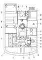
- FIG. 2 is an enlarged plan view showing the upper swing body with the cab and the building cover omitted.
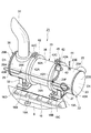
- FIG. 3 is an enlarged perspective view of the main part showing the exhaust gas treatment device attached to the engine.
- FIG. 4 is a front view showing the exhaust gas treatment device together with the hydraulic pump.
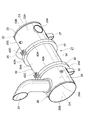
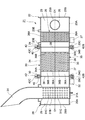
- FIG. 5 is a perspective view showing the exhaust gas treatment device alone.
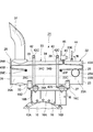
- FIG. 6 is a longitudinal sectional view showing the internal structure of the exhaust gas treatment device.
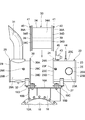
- FIG. 7 is an exploded perspective view showing a state where the filter cylinder and the gasket are removed from the upstream cylinder and the downstream cylinder.
- FIG. 1 is a front view showing a hydraulic excavator provided with an exhaust gas treatment device according to an embodiment of the present invention.
- FIG. 2 is an enlarged plan view showing the upper swing body with the cab and the building cover omitted.
- FIG. 3
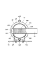
- FIG. 8 is an enlarged cross-sectional view of a main part when the upstream cylinder is attached to the processing apparatus support bracket as viewed from the direction of arrows VIII-VIII in FIG.
- FIG. 9 is a front view showing a state in which the filter cylinder is connected between the upstream cylinder and the downstream cylinder.
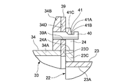
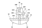
- FIG. 10 is an enlarged cross-sectional view of a main part showing a state where the pin insertion hole of the gasket is inserted into the positioning pin of the filter cylinder.
- FIG. 11 is an enlarged cross-sectional view of a main part showing a state where the positioning pin of the filter cylinder is inserted into the cutout groove of the upstream cylinder.
- FIG. 12 is an enlarged cross-sectional view of a main part showing a state in which the positioning pin of the filter cylinder is in contact with the bottom surface of the cutout groove.
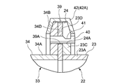
- FIG. 13 is an essential part enlarged cross-sectional view showing a state in which the front flange portion of the filter cylinder and the flange portion of the upstream cylinder are fixed by a clamp device.
- FIG. 14 is an exploded perspective view similar to FIG. 7 showing a modification of the positioning pin and the notch groove.
- FIG. 15 is a perspective view of an exhaust gas processing apparatus similar to FIG. 3 showing a modification in which the upstream cylinder, the downstream cylinder, and the filter cylinder are connected using bolts and nuts.
- a particulate matter removal device that removes particulate matter (PM) discharged from an engine by DPF is exemplified.
- the exhaust gas treatment device used in the present embodiment includes an upstream cylinder containing the oxidation catalyst and the silencer cylinder, a downstream cylinder containing the silencer cylinder, and a filter cylinder containing the DPF.
- an upstream cylinder containing the oxidation catalyst and the silencer cylinder a downstream cylinder containing the silencer cylinder
- a filter cylinder containing the DPF are connected in series using a V-shaped clamping device and attached to the engine side by a support leg.
- reference numeral 1 denotes a hydraulic excavator as a typical example of a construction machine, which constitutes a vehicle body to which the present embodiment is applied.
- the hydraulic excavator 1 is a self-propelled crawler-type lower traveling body 2 and is mounted on the lower traveling body 2 through a turning device 3 so as to be capable of turning, and together with the lower traveling body 2, an upper part constituting a vehicle body.
- the revolving body 4 and the work device 5 that is provided on the front side of the upper revolving body 4 so as to be able to move up and down and perform excavation work and the like are roughly configured.
- the upper swing body 4 includes a swing frame 6, a cab 7, an engine 8, an exhaust gas processing device 21, and the like which will be described later.
- the revolving frame 6 is a revolving frame serving as a base of the upper revolving unit 4, and the revolving frame 6 forms a strong support structure and is attached on the lower traveling unit 2 via the revolving device 3.
- the revolving frame 6 is provided with a thick bottom plate 6A extending in the front and rear directions, and standing on the bottom plate 6A, and in the front and rear directions with a predetermined interval in the left and right directions.
- the left side frame 6F is fixed to the front end of each left extension beam 6D and extends in the front and rear directions
- the right side frame 6G is fixed to the front end of each right extension beam 6E and extends in the front and rear directions. ing.
- cab 7 is a cab (see FIG. 1) mounted on the left front side of the revolving frame 6, and the cab 7 defines an operator's cab. Inside the cab 7, a driver's seat on which an operator is seated, various operation levers (none of which are shown), and the like are disposed.
- an engine 8 is an engine mounted horizontally on the rear side of the turning frame 6, and this engine 8 is constituted by, for example, a diesel engine. Further, as shown in FIG. 2, an exhaust pipe 9 that forms a part of an exhaust gas passage for exhaust gas exhaust is provided on the right side of the engine 8. A device 21 is attached.
- the engine 8 has high efficiency and excellent durability, but exhausts harmful substances such as particulate matter (PM), nitrogen oxide (NOx), carbon monoxide (CO), etc. Will be discharged together. Therefore, the exhaust gas treatment device 21 attached to the exhaust pipe 9 includes an oxidation catalyst 26 that oxidizes and removes carbon monoxide (CO) and the like and a DPF 35 that collects and removes particulate matter, as will be described later. It consists of
- a hydraulic pump 10 is attached to the right side of the engine 8, and the hydraulic pump 10 is driven by the engine 8 to discharge operating hydraulic oil toward various hydraulic actuators mounted on the hydraulic excavator 1.
- the left end facing the engine 8 is a flange portion 10 ⁇ / b> A, and the flange portion 10 ⁇ / b> A is bolted to the engine 8.
- a processing device support bracket 16 described later is attached together.
- a heat exchanger 11 is provided on the left side of the engine 8.
- the heat exchanger 11 includes, for example, a radiator, an oil cooler, an intercooler, and the like.
- the engine cooling water, hydraulic oil, and supercharged air are cooled by releasing heat.
- Numeral 12 is a hydraulic oil tank that is located on the front side of the hydraulic pump 10 and is mounted on the right side of the revolving frame 6.
- the hydraulic oil tank 12 stores hydraulic oil supplied to the hydraulic pump 10.
- Reference numeral 13 denotes a fuel tank provided on the front side of the hydraulic oil tank 12, and this fuel tank 13 stores fuel supplied to the engine 8 therein.
- the counterweight 14 is a counterweight that is located on the rear side of the engine 8 and is attached to the rear end of the revolving frame 6.
- the counterweight 14 balances the weight of the work device 5.
- a building cover 15 is disposed on the front side of the counterweight 14, and the building cover 15 houses the engine 8, the hydraulic pump 10, the heat exchange device 11, and the like.
- a processing device support bracket 16 is provided on the right side of the engine 8.
- the processing device support bracket 16 constitutes a structure on the upper swing body 4 side that supports an exhaust gas processing device 21 described later. .
- the processing apparatus support bracket 16 is disposed on the support base 16A together with the flange portion 10A of the hydraulic pump 10 and the support base 16A, and is disposed on the support base 16A at intervals in the front and rear directions.
- the front mounting plate 16C and the rear mounting plate 16D which are supported in a vibration-proof manner via members 16B (only two are shown), are roughly configured.
- An exhaust gas processing device 21 is located on the upper right side of the engine 8 and is connected to the exhaust pipe 9.
- the exhaust gas processing device 21 forms an exhaust gas passage together with the exhaust pipe 9, and exhausts from the upstream side to the downstream side. During the circulation of the gas, harmful substances contained in the exhaust gas are removed. Further, the exhaust gas treatment device 21 is arranged in a vertically placed state extending in the front and rear directions above the engine 8 so that the front side in the front and rear directions is the upstream side and the rear side is the downstream side (FIG. 2). reference).
- the exhaust gas treatment device 21 includes three upstream cylinders 22, a downstream cylinder 28, and a filter cylinder 33 as a purification section cylinder.
- the cylinders are configured to be connected in series so that the axes O1-O1 passing through the axis center coincide with each other.
- the upstream cylinder 22 accommodates a silencer cylinder 25B and an oxidation catalyst 26 of an inflow pipe 25, which will be described later, and an outflow pipe, which will be described later, in the downstream cylinder 28.
- 31 silencer cylinders 31B are accommodated, and a filter cylinder 33 accommodates a DPF 35 described later.
- reference numeral 22 denotes an upstream cylinder that is located on the front side of the exhaust gas treatment device 21 and provided on the upstream side of the exhaust gas passage.
- the upstream cylinder 22 constitutes an inlet portion into which exhaust gas flows, and the upstream cylinder 22 includes a cylindrical case 23, an inlet pipe 25, an oxidation catalyst, which will be described later, as shown in FIGS. 26 and support legs 27 are generally configured.
- Reference numeral 23 denotes a cylindrical case constituting an outer shell of the upstream cylindrical body 22, and the cylindrical case 23 closes the cylindrical portion 23A having a large cylindrical shape and the front side (upstream side) of the cylindrical portion 23A.
- the lid portion 23B is provided, and the flange portion 23C is provided in a bowl shape over the entire circumference at the rear (downstream) end of the cylindrical portion 23A.
- the flange portion 23C is connected to a front flange portion 34B of a cylindrical case 34 described later via a gasket 39 described later.
- a connection surface 23D of the flange portion 23C is It is formed as an annular flat surface orthogonal to the axis O1-O1.
- the below-mentioned notch groove 24 is provided in the upper part side of the flange part 23C.
- the cylindrical case 23 is provided with two temperature sensor attachment ports 23E located at the upper part of the cylindrical portion 23A. As shown in FIGS. 3 and 4, the two temperature sensor attachment ports 23 ⁇ / b> E are for attaching temperature sensors 44 and 45 described later, and are disposed at two positions sandwiching an oxidation catalyst 26 described later in the front and rear directions. ing. Further, an upstream pressure extraction portion 23F, for example, located on the right side is provided at the rear side position of the cylindrical portion 23A, and the pressure extraction portion 23F will be described later among the pressures of the exhaust gas flowing through the exhaust gas passage.
- the pressure sensor 43 takes out the pressure on the upstream side of the DPF 35, and a pressure sensor 43 (described later) is connected via an upstream pipe 43A.
- Reference numeral 24 denotes a notch groove provided on the upper side of the flange portion 23C of the cylindrical case 23 constituting the upstream cylinder 22, and the notch groove 24 is engaged with a positioning pin 40 of a filter cylinder 33 described later. It is.
- the notch groove 24 is one vertical groove extending linearly upward and downward by notching the upper end side of the flange portion 23C from the outer peripheral edge portion toward the center.
- the lower end part is a groove bottom part 24A.
- the notch groove 24 is engaged with the positioning pin 40 of the filter cylinder 33 to guide the filter cylinder 33 in the radial direction with respect to the upstream cylinder 22, and is formed in the groove bottom 24 ⁇ / b> A of the notch groove 24.
- the filter cylinder 33 is positioned so as to be coaxial with the upstream cylinder 22 in a state where the positioning pins 40 are in contact with each other.
- the inflow pipe 25 is an inflow pipe provided on the front side (upstream side) of the cylindrical case 23, and the inflow pipe 25 penetrates the cylindrical portion 23A of the cylindrical case 23 in the radial direction (see FIG. 8).
- one end side of the inflow pipe 25 protruding from the cylindrical case 23 extends to the left side toward the exhaust pipe 9 and is connected to the exhaust pipe 9.
- the other end side of the inflow pipe 25 is closed by a closing plate 25A.
- the inflow pipe 25 constitutes a silencer cylinder 25B inside the cylindrical case 23, and exhaust gas passes through a large number of small holes 25C provided in the silencer cylinder 25B. Is reduced.
- An oxidation catalyst 26 is located downstream of the inflow pipe 25 and is accommodated in the cylindrical case 23.
- the oxidation catalyst 26 constitutes one of the processing members for purifying the exhaust gas.
- the oxidation catalyst 26 is made of, for example, a ceramic cell-like cylindrical body having an outer diameter equivalent to the inner diameter of the cylindrical portion 23 ⁇ / b> A.
- Through-hole 26A is formed, and the inner surface is coated with a noble metal such as platinum (Pt).
- the oxidation catalyst 26 oxidizes and removes carbon monoxide (CO), hydrocarbons (HC), etc. contained in the exhaust gas by circulating the exhaust gas through the through holes 26A at a predetermined temperature. Nitrogen oxide (NO) is removed as nitrogen dioxide (NO 2 ).
- Reference numeral 27 denotes a support leg as a support member provided on the lower surface side of the cylindrical case 23 (cylindrical portion 23A).
- the support leg 27 bends the plate body into a substantially W shape as shown in FIG.
- the upper end side is fixed to the lower surface of the cylindrical portion 23A by means of welding or the like.
- the lower end side of the support leg 27 is bolted to the front mounting plate 16 ⁇ / b> C of the processing apparatus support bracket 16.
- the upstream cylindrical body 22 is configured to be fixed to the processing apparatus support bracket 16 attached to the upper swing body 4 side via the support legs 27.
- 28 indicates a downstream cylinder provided on the downstream side of the upstream cylinder 22 and located on the rear side of the exhaust gas treatment device 21.
- the downstream cylinder 28 is disposed on the opposite side of the upstream cylinder 22 with a filter cylinder 33 to be described later interposed therebetween, and constitutes an outlet portion through which exhaust gas flows out.
- the downstream cylindrical body 28 is roughly constituted by a cylindrical case 29, an outflow pipe 31, and a support leg 32 which will be described later.
- the cylindrical case 29 is a cylindrical case that constitutes the outer shell of the downstream cylindrical body 28.
- the cylindrical case 29 is substantially the same as the cylindrical case 23 of the upstream cylindrical body 22, and a cylindrical portion 29A having a large-diameter cylindrical shape, A lid portion 29B provided by closing the rear side (downstream side) of the cylindrical portion 29A, and a flange portion 29C provided in a bowl shape over the entire circumference at the front side (upstream side) end portion of the cylindrical portion 29A. It is comprised by.
- the flange portion 29C is connected to a rear flange portion 34C of a cylindrical case 34 described later via a gasket 39 described later, and a connection surface 29D of the flange portion 29C is , Formed as an annular flat surface orthogonal to the axis O1-O1.
- the flange portion 29C is provided with a notch groove 30 described later.
- a downstream pressure extraction portion 29E for example, located on the right side is provided at the rear side position of the cylindrical portion 29A.
- the pressure extraction portion 29E includes the DPF 35 of the pressure of the exhaust gas flowing through the exhaust gas passage.
- a pressure sensor 43 which will be described later, is connected through a downstream pipe 43B.
- Reference numeral 30 denotes a notch groove provided on the upper side of the flange portion 29C of the cylindrical case 29 constituting the downstream cylinder 28.
- the notch groove 30 is engaged with the positioning pin 40 of the filter cylinder 33.
- the notch groove 24 provided in the flange portion 23 ⁇ / b> C of the upstream cylindrical body 22 is substantially opposed to the front and rear directions.
- the notch groove 30 is one vertical groove extending linearly upward and downward by notching the upper end side of the flange portion 29C from the outer peripheral edge portion toward the center.
- the lower end part is the groove bottom part 30A.
- the notch groove 30 engages with the positioning pin 40 of the filter cylinder 33 to guide the filter cylinder 33 in the radial direction with respect to the downstream cylinder 28, so that the notch groove 30 is formed in the groove bottom portion 30 ⁇ / b> A of the notch groove 30.
- the filter cylinder 33 is positioned so as to be coaxial with the downstream cylinder 28 in a state where the positioning pins 40 are in contact with each other.
- the outflow pipe 31 is an outflow pipe called a tail pipe provided on the rear side (downstream side) of the cylindrical case 29.
- the outflow pipe 31 penetrates the cylindrical portion 29A of the cylindrical case 29 in the radial direction (FIG. 6). reference). Further, the upper end side of the outflow pipe 31 protruding from the cylindrical case 29 protrudes above the building cover 15 shown in FIG. 1 and is released to the atmosphere. On the other hand, the lower end side of the outflow pipe 31 is closed by a closing plate 31A.
- the outflow pipe 31 constitutes a silencer cylinder 31B inside the cylindrical case 29, and exhaust gas passes through a large number of small holes 31C provided in the silencer cylinder 31B. Is reduced.
- Reference numeral 32 denotes a support leg as a support member provided on the lower surface side of the cylindrical case 29 (cylindrical portion 29 ⁇ / b> A).
- the support leg 32 has a substantially W-shaped plate as in the case of the support leg 27 of the upstream cylinder 22.
- the upper end side is fixed to the lower surface of the cylindrical portion 29A.
- the lower end side of the support leg 32 is configured to be bolted to the rear mounting plate 16D of the processing apparatus support bracket 16.
- the downstream cylinder 28 is configured to be fixed to the processing apparatus support bracket 16 attached to the upper swing body 4 side via the support legs 32.
- the filter cylinder 33 indicates one filter cylinder provided in series between the upstream cylinder 22 and the downstream cylinder 28.
- the filter cylinder 33 constitutes a purification section cylinder having a processing member for purifying exhaust gas.
- the filter cylinder 33 is roughly constituted by a cylindrical case 34 described later and a DPF 35.
- the cylindrical case 34 is a cylindrical case constituting the outer shell of the filter cylinder 33, and the cylindrical case 34 accommodates the DPF 35 therein.
- the cylindrical case 34 includes a cylindrical portion 34A having substantially the same outer diameter as the cylindrical case 23 of the upstream cylindrical body 22 and the cylindrical case 29 of the downstream cylindrical body 28, and a front side (upstream side) of the cylindrical portion 34A.
- the front flange 34B provided in a bowl shape over the entire circumference
- a rear flange provided at the rear (downstream) end of the cylindrical section 34A in a bowl shape over the entire circumference. It is roughly constituted by the part 34C.
- the front flange portion 34B is connected to the flange portion 23C of the upstream cylindrical body 22 (cylindrical case 23) via a gasket 39 described later.
- the connection surface 34D of the front flange portion 34B is formed as an annular flat surface orthogonal to the axis O1-O1.
- the rear flange portion 34C is connected to the flange portion 29C of the downstream cylindrical body 28 (tubular case 29) via a gasket 39.
- the connection surface 34E of the rear flange portion 34C is formed as an annular flat surface orthogonal to the axis O1-O1.
- the front flange portion 34B and the rear flange portion 34C are each provided with a positioning pin 40 described later.
- the DPF 35 is a DPF (particulate matter removal filter) accommodated in the cylindrical case 34, and this DPF 35 constitutes one of the processing members.
- the DPF 35 is provided over the entire circumference on the outer peripheral side of the filter main body 36 and the filter main body 36 formed in a cylindrical shape by a porous member made of, for example, a ceramic material.
- the cushioning material layer 37 and a heat insulating material layer 38 provided over the entire circumference on the outer peripheral side of the cushioning material layer 37 are roughly configured.
- the filter main body 36 is formed in a cellular structure having a honeycomb structure in which a large number of small holes 36A are provided in the axial direction, and each small hole 36A has a different end portion alternately adjacent to each other by a plugging member 36B. It is blocked.
- the filter body 36 collects particulate matter by passing the exhaust gas flowing into each small hole 36A from the upstream side through the porous material, and flows only the exhaust gas downstream through the adjacent small hole 36A.
- the particulate matter collected by the filter main body 36 is removed by combustion, but a part of it becomes ash and gradually accumulates in the small holes 36A.
- other unburned residues such as heavy metals and calcium in the engine oil are gradually deposited. Therefore, the pressure sensor 43 described later measures the pressure on the upstream side and the pressure on the downstream side of the DPF 35, and when the pressure difference between the upstream side and the downstream side reaches a predetermined value, the DPF 35 is connected to the cylinder of the filter cylinder 33. It removes from the shape case 34 and becomes a structure which cleans a deposit.
- each gasket 39 is formed as an annular body substantially similar to the front flange portion 34 ⁇ / b> B and the rear flange portion 34 ⁇ / b> C of the cylindrical case 34 using a metal plate such as stainless steel, for example. Is formed.
- Each gasket 39 hermetically seals the connecting portion between the flange portion 23C of the cylindrical case 23 and the front flange portion 34B of the cylindrical case 34, and also between the flange portion 29C of the cylindrical case 29 and the cylindrical case 34.
- the connection portion with the rear flange portion 34C is hermetically sealed.
- one pin insertion hole 39 ⁇ / b> A through which a positioning pin 40 described later is inserted is formed in the upper end side of each gasket 39.
- Reference numeral 40 denotes two positioning pins.
- One positioning pin 40 is provided on each of the front flange portion 34B and the rear flange portion 34C of the cylindrical case 34 constituting the filter cylinder 33. ing. As shown in FIGS. 9 to 13, these positioning pins 40 hook and hold the gasket 39, and the notch groove 24 provided in the flange portion 23 ⁇ / b> C of the upstream cylinder 22 and the flange portion of the downstream cylinder 28. It engages with a notch groove 30 provided in 29C.
- each positioning pin 40 is formed of a cylindrical pin having a slightly smaller diameter than the groove width of the cutout grooves 24 and 30 as a whole, and for example, a front flange portion 34B and a rear flange portion 34C using means such as press fitting. It is fixed to.
- the positioning pin 40 provided on the front flange portion 34B protrudes from the connection surface 34D of the front flange portion 34B toward the upstream cylindrical body 22, and the positioning pin 40 provided on the rear flange portion 34C includes the rear flange. Projecting from the connection surface 34E of the portion 34C toward the downstream cylindrical body 28.
- the filter cylinder 33 is inserted between the upstream cylinder 22 and the downstream cylinder 28, and the upstream cylinder
- the filter cylinder 33 is moved downstream from the upstream cylinder 22.
- the cylindrical body 28 can be positioned so as to be coaxial with the axis O1-O1.
- a concave portion 41 described later is provided at an intermediate portion of each positioning pin 40.
- the recessed portion 41 is a recessed portion as an engaging portion provided at an intermediate portion of each positioning pin 40, and the recessed portion 41 has a substantially U-shaped cross section on the upper surface side of the positioning pin 40 as shown in FIG. It is formed by cutting out with a shape.
- the recessed portion 41 includes a groove bottom surface 41A positioned in the middle of the positioning pin 40 in the axial direction, a vertical surface 41B positioned on the distal end side of the positioning pin 40 and rising vertically from the groove bottom surface 41A, and a positioning pin It has an inclined surface 41C which is located on the base end side of 40 and rises obliquely upward from the groove bottom surface 41A portion toward the cylindrical case 34.
- each of these clamping devices 42 includes two semicircular arc-shaped frame bodies 42A and 42A having a substantially V-shaped cross-sectional shape, and one end side of each frame body 42A.
- the hinge part 42B connected so that rotation is possible, and the bolt and nut type connection part 42C which connects the other end side of each frame 42A are comprised roughly.
- the clamping device 42 clamps the flange portion 23C of the upstream cylinder 22 and the front flange portion 34B of the filter cylinder 33 in the axial direction with the gasket 39 interposed therebetween, and the flange section 29C of the downstream cylinder 28 and the filter The rear flange portion 34C of the cylindrical body 33 is tightened in the axial direction with the gasket 39 interposed therebetween.
- the pressure sensor 43 is a pressure sensor provided on the outer peripheral side of the upstream cylindrical body 22, and the pressure sensor 43 is used to estimate the amount of accumulation of particulate matter, unburned residue, etc., on the upstream side and downstream side of the DPF 35. (Pressure difference) is detected.
- the pressure sensor 43 has an upstream pipe 43A connected to the pressure outlet 23F of the cylindrical case 23 of the upstream cylinder 22, and a downstream pipe 43B connected to the pressure outlet 29E of the cylindrical case 29 of the downstream cylinder 28. It is connected to the.
- An upstream temperature sensor 44 is provided on the upstream side of the cylindrical case 23 of the upstream cylindrical body 22, and the upstream temperature sensor 44 is attached to a temperature sensor attachment port 23 ⁇ / b> E located on the upstream side of the cylindrical case 23. , Connected to a controller (not shown). The upstream temperature sensor 44 detects the temperature of the exhaust gas flowing into the cylindrical case 23 in order to confirm whether the temperature is such that the oxidation catalyst 26 can function.
- downstream temperature sensor 45 is a downstream temperature sensor provided on the downstream side of the cylindrical case 23 of the upstream cylinder 22, and can this downstream temperature sensor 45 oxidize (regenerate) the particulate matter collected by the DPF 35? In order to confirm, the temperature of the exhaust gas that has passed through the oxidation catalyst 26 is detected.
- the exhaust gas treatment device 21 has the above-described configuration, and when the engine 8 is operated to perform excavation work or the like by the hydraulic excavator 1, particulate matter, Exhaust gas containing harmful substances such as nitrogen oxides is discharged, and this exhaust gas is introduced into the exhaust gas processing device 21 through the inflow pipe 25.
- the exhaust gas treatment device 21 includes carbon monoxide (CO), hydrocarbon (HC), etc. contained in the exhaust gas. Is oxidized and removed. Then, when the exhaust gas that has passed through the oxidation catalyst 26 passes through the DPF 35 accommodated in the filter cylinder 33, the particulate matter contained in the exhaust gas is collected by the filter body 36 of the DPF 35, The collected particulate matter is removed by combustion (regeneration).
- CO carbon monoxide
- HC hydrocarbon
- the exhaust gas purified by the exhaust gas treatment device 21 is silenced by the silencer cylinder 31B of the outflow pipe 31 in the downstream cylinder 28 and then discharged to the outside through the outflow pipe 31.
- the particulate matter collected by the filter main body 36 of the DPF 35 is removed by combustion, but a part thereof becomes ash and gradually accumulates in the small holes 36A of the filter main body 36.
- other unburned residues such as heavy metals and calcium in the engine oil are gradually deposited.
- the pressure sensor 43 measures the pressure difference between the upstream side and the downstream side of the DPF 35, and when the pressure difference reaches a predetermined value, the DPF 35 is removed from the cylindrical case 34 of the filter cylinder 33, The deposit needs to be cleaned.
- the clamping device 42 that connects the flange 23C of the upstream cylinder 22 and the front flange 34B of the filter cylinder 33 is removed, and then the flange part of the downstream cylinder 28 is removed.
- the clamp device 42 that connects 29C and the rear flange portion 34C of the filter cylinder 33 is removed.
- the upper cylinder 22 is fixed to the processing apparatus support bracket 16 via the support leg 27 and the downstream cylinder 28 is fixed to the processing apparatus support bracket 16 via the support leg 32. Only the filter cylinder 33 can be removed upward from the upstream cylinder 22 and the downstream cylinder 28 fixed to the fourth side.
- the filter cylinder 33 can be removed upward with respect to the upstream cylinder 22 and the downstream cylinder 28. Therefore, even when the exhaust gas processing device 21 is arranged in a narrow space in the building cover 15 together with the mounted devices such as the engine 8 and the hydraulic pump 10, the operator is obstructed by other mounted devices. Only the filter cylinder 33 can be removed safely and easily.
- compressed air is blown onto the filter main body 36 of the DPF 35 accommodated in the filter cylinder 33 using, for example, an air gun to remove particulate matter ash and unburned residue accumulated in the small holes 36A. By doing so, the DPF 35 can be cleaned.
- the filter cylinder 33 containing the DPF 35 is connected again between the upstream cylinder 22 and the downstream cylinder 28.
- the pin insertion holes 39A of the gasket 39 are inserted into the positioning pins 40 at the front and rear of the filter cylinder 33.
- the gasket 39 is temporarily fixed to the front flange portion 34B and the rear flange portion 34C of the filter cylinder 33.
- the filter cylinder 33 is inserted between the upstream cylinder 22 and the downstream cylinder 28.
- connection surface 34D of the front flange portion 34B of the filter cylinder 33 and the connection surface 23D of the flange portion 23C of the upstream cylinder 22 face each other via the gasket 39, and the rear side of the filter cylinder 33
- connection surface 34E of the flange portion 34C and the connection surface 29D of the flange portion 29C of the downstream cylindrical body 28 can face each other via the gasket 39.
- the positioning pin 40 provided on the front flange portion 34B of the filter cylinder 33 is engaged with the notch groove 24 provided on the flange portion 23C of the upstream cylinder 22, Similarly, the positioning pin 40 provided in the rear flange portion 34C of the filter cylinder 33 engages with the notch groove 30 provided in the flange portion 29C of the downstream cylinder 28. Then, as shown in FIG. 12, the positioning pin 40 provided on the front flange portion 34B contacts the groove bottom portion 24A of the notch groove 24, and similarly, the positioning pin 40 provided on the rear flange portion 34C is notched.
- the filter cylinder 33 can be positioned so as to be coaxial with the upstream cylinder 22 and the downstream cylinder 28 while being in contact with the groove bottom portion 30 ⁇ / b> A of 30.
- the filter cylinder 33 is positioned coaxially with the axis O1-O1 with respect to the upstream cylinder 22 and the downstream cylinder 28 as shown in FIG.
- the front flange portion 34 ⁇ / b> B and the flange portion 23 ⁇ / b> C of the upstream cylindrical body 22 are tightened using the clamp device 42.
- the rear flange portion 34C of the filter cylinder 33 and the flange portion 29C of the downstream cylinder 28 are tightened using the clamp device 42.
- the gap between the flange portion 23C of the upstream cylinder 22 and the front flange portion 34B of the filter cylinder 33 can be fixed in a state of being airtightly sealed by the gasket 39.
- the flange 29C of the downstream cylinder 28 and the rear flange 34C of the filter cylinder 33 can be fixed in a state of being airtightly sealed by the gasket 39. Therefore, the upstream cylinder 22, the downstream cylinder 28, and the filter cylinder 33 can be connected in series along the axis O1-O1.
- the exhaust gas treatment device 21 is provided in the front flange portion 34B of the filter cylinder 33 when the filter cylinder 33 is connected between the upstream cylinder 22 and the downstream cylinder 28.
- the positioning pin 40 is engaged with the cutout groove 24 of the upstream cylinder 22, and the positioning pin 40 provided on the rear flange portion 34 ⁇ / b> C is engaged with the cutout groove 30 of the downstream cylinder 28.
- the filter cylinder 33 can be positioned coaxially with respect to the upstream cylinder 22 and the downstream cylinder 28.
- the pin insertion hole 39A of the gasket 39 is inserted into the positioning pin 40 provided in the front flange portion 34B and the rear flange portion 34C of the filter cylinder 33. Accordingly, the filter cylinder 33 is interposed between the upstream cylinder 22 and the downstream cylinder 28 in a state where the gasket 39 is temporarily fixed to the front flange part 34B and the rear flange part 34C of the filter cylinder 33. Can be connected to.
- each positioning pin 40 of the filter cylinder 33 is provided with a recessed portion 41 having a groove bottom surface 41A located in the middle of the axial direction, a vertical surface 41B rising from the groove bottom surface 41A, and an inclined surface 41C. ing.
- the gasket 39 when the gasket 39 is moved to the cylindrical case 34 side, the inner peripheral edge portion of the pin insertion hole 39A of the gasket 39 moves along the inclined surface 41C of the recessed portion 41.
- the hole center of the pin insertion hole 39 ⁇ / b> A of the gasket 39 and the axial center of the positioning pin 40 can be matched, and the gasket 39 can be positioned coaxially with the cylindrical case 34.
- the gasket 39 can be reliably disposed between the rear flange portion 34C of the filter cylinder 33 and the flange portion 29C of the downstream cylinder 28.
- the present invention is not limited to this, and two positioning pins 40 may be provided on each of the front flange portion 34B and the rear flange portion 34C, for example, as in a modification shown in FIG.
- two pin insertion holes 39A are provided in each gasket 39
- two notch grooves 24 are provided in the flange 23C of the upstream cylinder 22
- two are provided in the flange 29C of the downstream cylinder 28.
- the notch groove 30 is provided.
- the flange between the front flange portion 34B of the filter cylinder 33 and the flange portion 23C of the upstream cylinder 22 and between the rear flange portion 34C of the filter cylinder 33 and the downstream cylinder 28 is provided.
- the case where it connected with the part 29C using the clamp apparatus 42 is illustrated.
- the present invention is not limited to this, and a plurality of bolts and nuts 46 are used instead of the clamping device 42 as in another modification shown in FIG. 15, for example, between the front flange portion 34B and the flange portion 23C.
- the rear flange portion 34C and the flange portion 29C may be connected to each other.
- the DPF 35 is used as a processing member for purifying exhaust gas is illustrated.
- the present invention is not limited to this.
- a NOx treatment device may be applied as the exhaust gas treatment device.
- a selective reduction catalyst that reduces NOx and a urea water injection valve that injects urea water into the selective reduction catalyst correspond to the processing member.
- the exhaust gas treatment device 21 is mounted on the hydraulic excavator 1 including the crawler type lower traveling body 2 as an example.
- the present invention is not limited to this, and may be configured to be mounted on a hydraulic excavator including a wheel-type lower traveling body made of, for example, a tire. Besides, it can be widely mounted on other construction machines such as dump trucks and hydraulic cranes.
Landscapes
- Engineering & Computer Science (AREA)
- Chemical & Material Sciences (AREA)
- General Engineering & Computer Science (AREA)
- Mechanical Engineering (AREA)
- Combustion & Propulsion (AREA)
- Chemical Kinetics & Catalysis (AREA)
- Materials Engineering (AREA)
- Health & Medical Sciences (AREA)
- Toxicology (AREA)
- Exhaust Gas After Treatment (AREA)
- Processes For Solid Components From Exhaust (AREA)
Abstract
Description
2 下部走行体(車体)
4 上部旋回体(車体)
8 エンジン
9 排気管(排気ガス通路)
21 排気ガス処理装置
22 上流筒体
23,29,34 筒状ケース
23C,29C フランジ部
23D,29D,34D,34E 接続面
24,30 切欠溝
26 酸化触媒(処理部材)
27,32 支持脚(支持部材)
28 下流筒体
33 フィルタ用筒体(浄化部筒体)
34B 前側フランジ部
34C 後側フランジ部
35 DPF(処理部材)
39 ガスケット
39A ピン挿通孔
40 位置決めピン
41 凹窪部(係合部)
41A 溝底面
41B 鉛直面
41C 傾斜面
42 クランプ装置
Claims (5)
- 車体に搭載されたエンジン(8)の排気ガス通路(9)に設けられた上流筒体(22)と、該上流筒体(22)の下流側に設けられた下流筒体(28)と、前記上流筒体(22)と下流筒体(28)との間に軸線(O1-O1)方向に直列に取付け、取外し可能に接続して設けられ、排気ガスを浄化処理するための処理部材(35)が内蔵された浄化部筒体(33)とを備えてなる排気ガス処理装置において、
前記上流筒体(22)、下流筒体(28)、浄化部筒体(33)には、互いに対面して接続される筒体端部に平坦な接続面(23D,29D,34D,34E)を有するフランジ部(23C,29C,34B,34C)を設け、
前記浄化部筒体(33)の前側フランジ部(34B)と後側フランジ部(34C)には、前記接続面(34D,34E)から前記上流側筒体(22)、下流筒体(28)に向けてそれぞれ突出する位置決めピン(40)を設け、
前記上流筒体(22)のフランジ部(23C)と前記下流筒体(28)のフランジ部(29C)には、前記位置決めピン(40)が係合することにより前記上流筒体(22)と下流筒体(28)とに対して前記浄化部筒体(33)を位置決めする切欠溝(24,30)をそれぞれ設ける構成としたことを特徴とする排気ガス処理装置。 - 前記上流筒体(22)のフランジ部(23C)、下流筒体(28)のフランジ部(29C)、浄化部筒体(33)のフランジ部(34B,34C)は、それぞれ軸線(O1-O1)と直交する方向に平坦な接続面(23D,29D,34D,34E)として形成してなる請求項1に記載の排気ガス処理装置。
- 前記上流筒体(22)と前記浄化部筒体(33)との間、及び前記下流筒体(28)と前記浄化部筒体(33)との間にはそれぞれガスケット(39)を設け、
該各ガスケット(39)には前記位置決めピン(40)が挿通されるピン挿通孔(39A)をそれぞれ設け、
前記位置決めピン(40)は、前記各ガスケット(39)の前記ピン挿通孔(39A)が挿通された状態で前記上流筒体(22)の切欠溝(24)と前記下流筒体(28)の切欠溝(30)とにそれぞれ係合する構成としてなる請求項1に記載の排気ガス処理装置。 - 前記位置決めピン(40)には、前記ガスケット(39)のピン挿通孔(39A)が挿通された状態で前記ガスケット(39)が係合する係合部(41)を設ける構成としてなる請求項3に記載の排気ガス処理装置。
- 前記上流筒体(22)と下流筒体(28)とは、支持部材(27,32)を介して前記車体側に固定する構成としてなる請求項1に記載の排気ガス処理装置。
Priority Applications (4)
| Application Number | Priority Date | Filing Date | Title |
|---|---|---|---|
| CN2009801218839A CN102057141B (zh) | 2008-09-08 | 2009-08-14 | 废气处理装置 |
| EP09811393.9A EP2336517B1 (en) | 2008-09-08 | 2009-08-14 | Exhaust gas processing device |
| US12/936,618 US8904766B2 (en) | 2008-09-08 | 2009-08-14 | Exhaust gas treatment device |
| JP2010527745A JP5133422B2 (ja) | 2008-09-08 | 2009-08-14 | 排気ガス処理装置 |
Applications Claiming Priority (2)
| Application Number | Priority Date | Filing Date | Title |
|---|---|---|---|
| JP2008229723 | 2008-09-08 | ||
| JP2008-229723 | 2008-09-08 |
Publications (1)
| Publication Number | Publication Date |
|---|---|
| WO2010026864A1 true WO2010026864A1 (ja) | 2010-03-11 |
Family
ID=41797036
Family Applications (1)
| Application Number | Title | Priority Date | Filing Date |
|---|---|---|---|
| PCT/JP2009/064358 Ceased WO2010026864A1 (ja) | 2008-09-08 | 2009-08-14 | 排気ガス処理装置 |
Country Status (6)
| Country | Link |
|---|---|
| US (1) | US8904766B2 (ja) |
| EP (1) | EP2336517B1 (ja) |
| JP (1) | JP5133422B2 (ja) |
| KR (1) | KR101571579B1 (ja) |
| CN (1) | CN102057141B (ja) |
| WO (1) | WO2010026864A1 (ja) |
Cited By (22)
| Publication number | Priority date | Publication date | Assignee | Title |
|---|---|---|---|---|
| JP2011196194A (ja) * | 2010-03-17 | 2011-10-06 | Yanmar Co Ltd | 排気ガス浄化装置 |
| JP2012071743A (ja) * | 2010-09-29 | 2012-04-12 | Yanmar Co Ltd | エンジン装置 |
| CN102758670A (zh) * | 2011-04-28 | 2012-10-31 | 卡特彼勒公司 | 废气后处理支承组件 |
| JP2012251564A (ja) * | 2012-09-28 | 2012-12-20 | Yanmar Co Ltd | エンジン装置 |
| JP2012251565A (ja) * | 2012-09-28 | 2012-12-20 | Yanmar Co Ltd | 排気ガス浄化装置付きエンジン及びその排気ガス浄化装置の取り付け方法 |
| JP2013072548A (ja) * | 2011-09-29 | 2013-04-22 | Mitoyo Kakoki Co Ltd | フェルール継手、フェルール継手の接続構造およびフェルール継手の接続方法 |
| CN103124836A (zh) * | 2010-09-15 | 2013-05-29 | 株式会社久保田 | 带有废气处理装置的发动机及该废气处理装置的安装方法 |
| JP2013189894A (ja) * | 2012-03-13 | 2013-09-26 | Kubota Corp | 排気処理装置付き多気筒エンジン |
| JP2014029157A (ja) * | 2013-09-30 | 2014-02-13 | Yanmar Co Ltd | エンジン装置 |
| JP2014040835A (ja) * | 2013-09-30 | 2014-03-06 | Yanmar Co Ltd | エンジン装置 |
| JP2014177946A (ja) * | 2014-05-29 | 2014-09-25 | Yanmar Co Ltd | エンジン装置 |
| JP2014238096A (ja) * | 2014-08-26 | 2014-12-18 | ヤンマー株式会社 | エンジン装置 |
| JP2015045337A (ja) * | 2014-11-12 | 2015-03-12 | ヤンマー株式会社 | エンジン装置 |
| KR101502497B1 (ko) * | 2011-03-03 | 2015-03-13 | 테네코 오토모티브 오퍼레이팅 컴파니 인코포레이티드 | 배기 처리 장치용 포카-요케 장착 시스템 |
| WO2015111433A1 (ja) | 2014-01-24 | 2015-07-30 | コベルコ建機株式会社 | 建設機械のマフラー |
| JP2018048578A (ja) * | 2016-09-21 | 2018-03-29 | 株式会社テイエルブイ | エゼクタ及び取付構造 |
| JP2018115574A (ja) * | 2017-01-17 | 2018-07-26 | フタバ産業株式会社 | フランジの締結構造 |
| CN108412585A (zh) * | 2018-05-16 | 2018-08-17 | 安徽全柴动力股份有限公司 | 一种颗粒捕集器及汽车 |
| WO2019124016A1 (ja) | 2017-12-19 | 2019-06-27 | 株式会社豊田自動織機 | 排気ガス浄化装置 |
| JP2019167847A (ja) * | 2018-03-22 | 2019-10-03 | 本田技研工業株式会社 | フランジの締結構造 |
| CN110652789A (zh) * | 2019-10-23 | 2020-01-07 | 张传保 | 一种吸烟室自动循环净化设备 |
| JP2020139501A (ja) * | 2019-02-27 | 2020-09-03 | エーバーシュペッヒャー・エグゾースト・テクノロジー・ゲーエムベーハー・ウント・コンパニー・カーゲー | 排気ガスコンバータボディ構造 |
Families Citing this family (34)
| Publication number | Priority date | Publication date | Assignee | Title |
|---|---|---|---|---|
| US8056671B2 (en) * | 2007-10-12 | 2011-11-15 | Mazda Motor Corporation | Exhaust-gas purification device disposition structure of vehicle |
| JP5185751B2 (ja) * | 2008-09-18 | 2013-04-17 | ヤンマー株式会社 | 排気ガス浄化装置 |
| GB2466483A (en) * | 2008-12-19 | 2010-06-30 | Agco Gmbh & Co | A vertical exhaust system for a vehicle |
| JP5033226B2 (ja) * | 2010-08-02 | 2012-09-26 | 株式会社小松製作所 | 作業車両 |
| JP5562777B2 (ja) * | 2010-09-16 | 2014-07-30 | 日立建機株式会社 | 建設機械 |
| EP2463503A1 (en) * | 2010-12-13 | 2012-06-13 | Perkins Engines Company Limited | A cylinder head mount |
| JP5707178B2 (ja) * | 2011-03-02 | 2015-04-22 | フタバ産業株式会社 | 排気浄化装置 |
| US9506597B2 (en) * | 2013-09-09 | 2016-11-29 | General Electric Company | Support system for an aftertreatment system for an engine |
| USD742936S1 (en) * | 2011-08-01 | 2015-11-10 | Joseph Vogele Ag | Control panel of road construction machine |
| USD668691S1 (en) * | 2012-02-01 | 2012-10-09 | Joseph Vögele AG | Cover for an exhaust port of a road construction machine |
| JP6033026B2 (ja) * | 2012-09-28 | 2016-11-30 | ヤンマー株式会社 | エンジン装置 |
| USD698831S1 (en) * | 2012-10-09 | 2014-02-04 | Cnh America Llc | Combined tractor windows and intake and exhaust |
| USD687075S1 (en) * | 2012-12-18 | 2013-07-30 | Cnh America Llc | Intake system for an agricultural work vehicle |
| CN104302884B (zh) * | 2013-03-29 | 2016-08-24 | 株式会社小松制作所 | 排气处理单元 |
| USD723591S1 (en) * | 2014-08-14 | 2015-03-03 | Cnh Industrial America Llc | Exhaust system for an agricultural work vehicle |
| USD724108S1 (en) * | 2014-08-14 | 2015-03-10 | Cnh Industrial America Llc | Exhaust system for an agricultural work vehicle |
| USD722330S1 (en) * | 2014-08-14 | 2015-02-10 | Cnh Industrial America Llc | Exhaust system for an agricultural work vehicle |
| JP6438341B2 (ja) * | 2014-10-15 | 2018-12-12 | ヤンマー株式会社 | 作業車両 |
| USD780808S1 (en) * | 2014-12-24 | 2017-03-07 | Ngk Insulators, Ltd. | Catalyst carrier for exhaust gas purification |
| USD785678S1 (en) * | 2014-12-24 | 2017-05-02 | Ngk Insulators, Ltd. | Catalyst carrier for exhaust gas purification |
| CN112901319B (zh) | 2014-12-31 | 2022-12-16 | 康明斯排放处理公司 | 紧密联接的单模块后处理系统 |
| GB2548040B (en) * | 2014-12-31 | 2020-11-25 | Cummins Emission Solutions Inc | Compact side inlet and outlet exhaust aftertreatment system |
| USD800174S1 (en) * | 2015-01-29 | 2017-10-17 | Cummins Emission Solutions, Inc. | Inner tube member with water dam for use in an aftertreatment system |
| JP6002257B2 (ja) * | 2015-02-04 | 2016-10-05 | 富士重工業株式会社 | 排気マフラ |
| JP6414488B2 (ja) * | 2015-03-05 | 2018-10-31 | いすゞ自動車株式会社 | 排気浄化装置のメンテナンス用具、及びメンテナンス方法 |
| US10465591B2 (en) | 2015-09-17 | 2019-11-05 | Cummins Emission Solutions Inc. | Aftertreatment system mounting assembly |
| JP6423332B2 (ja) * | 2015-11-25 | 2018-11-14 | ヤンマー株式会社 | エンジン装置 |
| US10948110B2 (en) * | 2016-12-13 | 2021-03-16 | Dynisco Instruments Llc | Multi-piece flow through connector |
| KR102633958B1 (ko) * | 2019-01-21 | 2024-02-05 | 현대자동차주식회사 | 자동차의 배기계용 클램핑 장치 |
| JP7222311B2 (ja) * | 2019-06-04 | 2023-02-15 | 株式会社豊田自動織機 | 配管の固定構造 |
| CN213144571U (zh) * | 2020-08-28 | 2021-05-07 | 济南天业工程机械有限公司 | 颗粒捕集装置 |
| CN112627942A (zh) * | 2020-10-27 | 2021-04-09 | 蓝晶卡特排放技术南京有限公司 | 柴油颗粒捕集器的再生方法以及系统 |
| CN112253863B (zh) * | 2020-10-29 | 2022-04-08 | 宝钛华神钛业有限公司 | 一种避免海绵钛氧化的单法兰机构 |
| EP4026995B1 (en) * | 2021-01-11 | 2025-12-31 | Volvo Penta Corporation | EXHAUST GAS TREATMENT DEVICE, SHIP AND GENERATOR |
Citations (4)
| Publication number | Priority date | Publication date | Assignee | Title |
|---|---|---|---|---|
| JPH08108076A (ja) * | 1994-10-11 | 1996-04-30 | Nippondenso Co Ltd | 触媒コンバータ |
| JP2001073756A (ja) * | 1999-09-01 | 2001-03-21 | Mitsubishi Motors Corp | 縦置き内燃機関の排気構造 |
| JP2003172120A (ja) * | 2001-12-05 | 2003-06-20 | Hino Motors Ltd | 排気浄化装置 |
| JP2005256615A (ja) * | 2004-03-09 | 2005-09-22 | Nissan Diesel Motor Co Ltd | エンジンの排気浄化装置 |
Family Cites Families (9)
| Publication number | Priority date | Publication date | Assignee | Title |
|---|---|---|---|---|
| DE3914756A1 (de) * | 1989-05-05 | 1990-11-22 | Platzer Schwedenbau Gmbh | Verfahren zur herstellung einer rohrflanschverbindung |
| JP2594265Y2 (ja) * | 1993-04-26 | 1999-04-26 | カルソニック株式会社 | 触媒コンバータ |
| US5408827A (en) * | 1993-09-28 | 1995-04-25 | Outboard Marine Corporation | Marine propulsion device with improved catalyst support arrangement |
| US5414993A (en) * | 1993-12-22 | 1995-05-16 | Caterpillar Inc. | Exhaust port liner and seal assembly |
| JP4115120B2 (ja) * | 2001-08-06 | 2008-07-09 | 株式会社小松製作所 | 内燃機関の排気ガス浄化装置 |
| EP2383444B1 (en) | 2004-02-02 | 2012-12-19 | Nissan Diesel Motor Co., Ltd. | Exhaust emission purifying apparatus for engine |
| JP2006144738A (ja) * | 2004-11-24 | 2006-06-08 | Nissan Motor Co Ltd | 排ガス浄化触媒の収容構造 |
| JP2007192328A (ja) * | 2006-01-19 | 2007-08-02 | Calsonic Kansei Corp | 金属シール部材を用いた継手構造 |
| JP5220855B2 (ja) * | 2008-07-10 | 2013-06-26 | 日立建機株式会社 | 排気ガス処理装置 |
-
2009
- 2009-08-14 JP JP2010527745A patent/JP5133422B2/ja not_active Expired - Fee Related
- 2009-08-14 KR KR1020107022105A patent/KR101571579B1/ko not_active Expired - Fee Related
- 2009-08-14 WO PCT/JP2009/064358 patent/WO2010026864A1/ja not_active Ceased
- 2009-08-14 CN CN2009801218839A patent/CN102057141B/zh not_active Expired - Fee Related
- 2009-08-14 EP EP09811393.9A patent/EP2336517B1/en not_active Not-in-force
- 2009-08-14 US US12/936,618 patent/US8904766B2/en active Active
Patent Citations (4)
| Publication number | Priority date | Publication date | Assignee | Title |
|---|---|---|---|---|
| JPH08108076A (ja) * | 1994-10-11 | 1996-04-30 | Nippondenso Co Ltd | 触媒コンバータ |
| JP2001073756A (ja) * | 1999-09-01 | 2001-03-21 | Mitsubishi Motors Corp | 縦置き内燃機関の排気構造 |
| JP2003172120A (ja) * | 2001-12-05 | 2003-06-20 | Hino Motors Ltd | 排気浄化装置 |
| JP2005256615A (ja) * | 2004-03-09 | 2005-09-22 | Nissan Diesel Motor Co Ltd | エンジンの排気浄化装置 |
Non-Patent Citations (1)
| Title |
|---|
| See also references of EP2336517A4 * |
Cited By (32)
| Publication number | Priority date | Publication date | Assignee | Title |
|---|---|---|---|---|
| CN102822469B (zh) * | 2010-03-17 | 2016-03-23 | 洋马株式会社 | 排气气体净化装置 |
| CN102822469A (zh) * | 2010-03-17 | 2012-12-12 | 洋马株式会社 | 排气气体净化装置 |
| JP2011196194A (ja) * | 2010-03-17 | 2011-10-06 | Yanmar Co Ltd | 排気ガス浄化装置 |
| US8926726B2 (en) | 2010-03-17 | 2015-01-06 | Yanmar Co., Ltd. | Exhaust gas purification device |
| CN103124836A (zh) * | 2010-09-15 | 2013-05-29 | 株式会社久保田 | 带有废气处理装置的发动机及该废气处理装置的安装方法 |
| CN103124836B (zh) * | 2010-09-15 | 2015-08-12 | 株式会社久保田 | 带有废气处理装置的发动机及该废气处理装置的安装方法 |
| JP2012071743A (ja) * | 2010-09-29 | 2012-04-12 | Yanmar Co Ltd | エンジン装置 |
| KR101502497B1 (ko) * | 2011-03-03 | 2015-03-13 | 테네코 오토모티브 오퍼레이팅 컴파니 인코포레이티드 | 배기 처리 장치용 포카-요케 장착 시스템 |
| CN102758670A (zh) * | 2011-04-28 | 2012-10-31 | 卡特彼勒公司 | 废气后处理支承组件 |
| JP2013072548A (ja) * | 2011-09-29 | 2013-04-22 | Mitoyo Kakoki Co Ltd | フェルール継手、フェルール継手の接続構造およびフェルール継手の接続方法 |
| JP2013189894A (ja) * | 2012-03-13 | 2013-09-26 | Kubota Corp | 排気処理装置付き多気筒エンジン |
| JP2012251565A (ja) * | 2012-09-28 | 2012-12-20 | Yanmar Co Ltd | 排気ガス浄化装置付きエンジン及びその排気ガス浄化装置の取り付け方法 |
| JP2012251564A (ja) * | 2012-09-28 | 2012-12-20 | Yanmar Co Ltd | エンジン装置 |
| JP2014040835A (ja) * | 2013-09-30 | 2014-03-06 | Yanmar Co Ltd | エンジン装置 |
| JP2014029157A (ja) * | 2013-09-30 | 2014-02-13 | Yanmar Co Ltd | エンジン装置 |
| WO2015111433A1 (ja) | 2014-01-24 | 2015-07-30 | コベルコ建機株式会社 | 建設機械のマフラー |
| US10215068B2 (en) | 2014-01-24 | 2019-02-26 | Kobelco Construction Machinery Co., Ltd. | Muffler for construction machine |
| KR20160089495A (ko) | 2014-01-24 | 2016-07-27 | 코벨코 겐키 가부시키가이샤 | 건설 기계의 머플러 |
| JP2014177946A (ja) * | 2014-05-29 | 2014-09-25 | Yanmar Co Ltd | エンジン装置 |
| JP2014238096A (ja) * | 2014-08-26 | 2014-12-18 | ヤンマー株式会社 | エンジン装置 |
| JP2015045337A (ja) * | 2014-11-12 | 2015-03-12 | ヤンマー株式会社 | エンジン装置 |
| JP2018048578A (ja) * | 2016-09-21 | 2018-03-29 | 株式会社テイエルブイ | エゼクタ及び取付構造 |
| JP2018115574A (ja) * | 2017-01-17 | 2018-07-26 | フタバ産業株式会社 | フランジの締結構造 |
| WO2019124016A1 (ja) | 2017-12-19 | 2019-06-27 | 株式会社豊田自動織機 | 排気ガス浄化装置 |
| JP2019108846A (ja) * | 2017-12-19 | 2019-07-04 | 株式会社豊田自動織機 | 排気ガス浄化装置 |
| KR20200081492A (ko) | 2017-12-19 | 2020-07-07 | 가부시키가이샤 도요다 지도숏키 | 배기 가스 정화 장치 |
| EP3730754A4 (en) * | 2017-12-19 | 2020-11-11 | Kabushiki Kaisha Toyota Jidoshokki | EXHAUST GAS CLEANING DEVICE |
| US11268431B2 (en) | 2017-12-19 | 2022-03-08 | Kabushiki Kaisha Toyota Jidoshokki | Exhaust gas purification device |
| JP2019167847A (ja) * | 2018-03-22 | 2019-10-03 | 本田技研工業株式会社 | フランジの締結構造 |
| CN108412585A (zh) * | 2018-05-16 | 2018-08-17 | 安徽全柴动力股份有限公司 | 一种颗粒捕集器及汽车 |
| JP2020139501A (ja) * | 2019-02-27 | 2020-09-03 | エーバーシュペッヒャー・エグゾースト・テクノロジー・ゲーエムベーハー・ウント・コンパニー・カーゲー | 排気ガスコンバータボディ構造 |
| CN110652789A (zh) * | 2019-10-23 | 2020-01-07 | 张传保 | 一种吸烟室自动循环净化设备 |
Also Published As
| Publication number | Publication date |
|---|---|
| CN102057141A (zh) | 2011-05-11 |
| CN102057141B (zh) | 2013-02-13 |
| JPWO2010026864A1 (ja) | 2012-02-02 |
| JP5133422B2 (ja) | 2013-01-30 |
| EP2336517A4 (en) | 2015-10-21 |
| US20110023472A1 (en) | 2011-02-03 |
| KR20110053309A (ko) | 2011-05-20 |
| KR101571579B1 (ko) | 2015-11-24 |
| US8904766B2 (en) | 2014-12-09 |
| EP2336517A1 (en) | 2011-06-22 |
| EP2336517B1 (en) | 2016-11-09 |
Similar Documents
| Publication | Publication Date | Title |
|---|---|---|
| JP5133422B2 (ja) | 排気ガス処理装置 | |
| JP5220855B2 (ja) | 排気ガス処理装置 | |
| JP5148714B2 (ja) | 排気ガス処理装置 | |
| JP4897757B2 (ja) | 排気ガス処理装置 | |
| JP5179286B2 (ja) | 排気ガス浄化装置 | |
| JP5220856B2 (ja) | 建設機械 | |
| JP4927796B2 (ja) | 排気ガス浄化装置 | |
| JP4981016B2 (ja) | 排気ガス浄化装置 | |
| JP5535696B2 (ja) | 排気ガス浄化装置 | |
| JP4933493B2 (ja) | 排気ガス浄化装置 | |
| KR102388645B1 (ko) | 배기 가스 정화 장치 | |
| JP6093982B2 (ja) | 建設機械 | |
| JP2010180793A (ja) | Egr装置及びこれを備えたエンジン |
Legal Events
| Date | Code | Title | Description |
|---|---|---|---|
| WWE | Wipo information: entry into national phase |
Ref document number: 200980121883.9 Country of ref document: CN |
|
| 121 | Ep: the epo has been informed by wipo that ep was designated in this application |
Ref document number: 09811393 Country of ref document: EP Kind code of ref document: A1 |
|
| WWE | Wipo information: entry into national phase |
Ref document number: 2010527745 Country of ref document: JP |
|
| ENP | Entry into the national phase |
Ref document number: 20107022105 Country of ref document: KR Kind code of ref document: A |
|
| WWE | Wipo information: entry into national phase |
Ref document number: 12936618 Country of ref document: US |
|
| REEP | Request for entry into the european phase |
Ref document number: 2009811393 Country of ref document: EP |
|
| WWE | Wipo information: entry into national phase |
Ref document number: 2009811393 Country of ref document: EP |
|
| NENP | Non-entry into the national phase |
Ref country code: DE |