WO2010029647A1 - コネクタ装置 - Google Patents
コネクタ装置 Download PDFInfo
- Publication number
- WO2010029647A1 WO2010029647A1 PCT/JP2008/069466 JP2008069466W WO2010029647A1 WO 2010029647 A1 WO2010029647 A1 WO 2010029647A1 JP 2008069466 W JP2008069466 W JP 2008069466W WO 2010029647 A1 WO2010029647 A1 WO 2010029647A1
- Authority
- WO
- WIPO (PCT)
- Prior art keywords
- connector device
- operation lever
- insulating housing
- end portion
- support mechanism
- Prior art date
- Legal status (The legal status is an assumption and is not a legal conclusion. Google has not performed a legal analysis and makes no representation as to the accuracy of the status listed.)
- Ceased
Links
Images


Classifications
-
- H—ELECTRICITY
- H01—ELECTRIC ELEMENTS
- H01R—ELECTRICALLY-CONDUCTIVE CONNECTIONS; STRUCTURAL ASSOCIATIONS OF A PLURALITY OF MUTUALLY-INSULATED ELECTRICAL CONNECTING ELEMENTS; COUPLING DEVICES; CURRENT COLLECTORS
- H01R13/00—Details of coupling devices of the kinds covered by groups H01R12/70 or H01R24/00 - H01R33/00
- H01R13/62—Means for facilitating engagement or disengagement of coupling parts or for holding them in engagement
- H01R13/639—Additional means for holding or locking coupling parts together, after engagement, e.g. separate keylock, retainer strap
-
- H—ELECTRICITY
- H01—ELECTRIC ELEMENTS
- H01R—ELECTRICALLY-CONDUCTIVE CONNECTIONS; STRUCTURAL ASSOCIATIONS OF A PLURALITY OF MUTUALLY-INSULATED ELECTRICAL CONNECTING ELEMENTS; COUPLING DEVICES; CURRENT COLLECTORS
- H01R13/00—Details of coupling devices of the kinds covered by groups H01R12/70 or H01R24/00 - H01R33/00
- H01R13/62—Means for facilitating engagement or disengagement of coupling parts or for holding them in engagement
- H01R13/629—Additional means for facilitating engagement or disengagement of coupling parts, e.g. aligning or guiding means, levers, gas pressure electrical locking indicators, manufacturing tolerances
- H01R13/62933—Comprising exclusively pivoting lever
-
- H—ELECTRICITY
- H01—ELECTRIC ELEMENTS
- H01R—ELECTRICALLY-CONDUCTIVE CONNECTIONS; STRUCTURAL ASSOCIATIONS OF A PLURALITY OF MUTUALLY-INSULATED ELECTRICAL CONNECTING ELEMENTS; COUPLING DEVICES; CURRENT COLLECTORS
- H01R12/00—Structural associations of a plurality of mutually-insulated electrical connecting elements, specially adapted for printed circuits, e.g. printed circuit boards [PCB], flat or ribbon cables, or like generally planar structures, e.g. terminal strips, terminal blocks; Coupling devices specially adapted for printed circuits, flat or ribbon cables, or like generally planar structures; Terminals specially adapted for contact with, or insertion into, printed circuits, flat or ribbon cables, or like generally planar structures
- H01R12/70—Coupling devices
- H01R12/71—Coupling devices for rigid printing circuits or like structures
-
- H—ELECTRICITY
- H01—ELECTRIC ELEMENTS
- H01R—ELECTRICALLY-CONDUCTIVE CONNECTIONS; STRUCTURAL ASSOCIATIONS OF A PLURALITY OF MUTUALLY-INSULATED ELECTRICAL CONNECTING ELEMENTS; COUPLING DEVICES; CURRENT COLLECTORS
- H01R12/00—Structural associations of a plurality of mutually-insulated electrical connecting elements, specially adapted for printed circuits, e.g. printed circuit boards [PCB], flat or ribbon cables, or like generally planar structures, e.g. terminal strips, terminal blocks; Coupling devices specially adapted for printed circuits, flat or ribbon cables, or like generally planar structures; Terminals specially adapted for contact with, or insertion into, printed circuits, flat or ribbon cables, or like generally planar structures
- H01R12/70—Coupling devices
- H01R12/82—Coupling devices connected with low or zero insertion force
- H01R12/85—Coupling devices connected with low or zero insertion force contact pressure producing means, contacts activated after insertion of printed circuits or like structures
- H01R12/88—Coupling devices connected with low or zero insertion force contact pressure producing means, contacts activated after insertion of printed circuits or like structures acting manually by rotating or pivoting connector housing parts
-
- H—ELECTRICITY
- H01—ELECTRIC ELEMENTS
- H01R—ELECTRICALLY-CONDUCTIVE CONNECTIONS; STRUCTURAL ASSOCIATIONS OF A PLURALITY OF MUTUALLY-INSULATED ELECTRICAL CONNECTING ELEMENTS; COUPLING DEVICES; CURRENT COLLECTORS
- H01R13/00—Details of coupling devices of the kinds covered by groups H01R12/70 or H01R24/00 - H01R33/00
- H01R13/62—Means for facilitating engagement or disengagement of coupling parts or for holding them in engagement
- H01R13/629—Additional means for facilitating engagement or disengagement of coupling parts, e.g. aligning or guiding means, levers, gas pressure electrical locking indicators, manufacturing tolerances
- H01R13/633—Additional means for facilitating engagement or disengagement of coupling parts, e.g. aligning or guiding means, levers, gas pressure electrical locking indicators, manufacturing tolerances for disengagement only
- H01R13/6335—Additional means for facilitating engagement or disengagement of coupling parts, e.g. aligning or guiding means, levers, gas pressure electrical locking indicators, manufacturing tolerances for disengagement only comprising a handle
-
- H—ELECTRICITY
- H01—ELECTRIC ELEMENTS
- H01R—ELECTRICALLY-CONDUCTIVE CONNECTIONS; STRUCTURAL ASSOCIATIONS OF A PLURALITY OF MUTUALLY-INSULATED ELECTRICAL CONNECTING ELEMENTS; COUPLING DEVICES; CURRENT COLLECTORS
- H01R13/00—Details of coupling devices of the kinds covered by groups H01R12/70 or H01R24/00 - H01R33/00
- H01R13/648—Protective earth or shield arrangements on coupling devices, e.g. anti-static shielding
Definitions
- a cable, a flexible printed circuit board (FPC), or the like is connected to a mating connector device attached to a main board such as a solid printed circuit board, and the cable or FPC is connected. And the other connector device.
- a first connector device that is a connector device and a second connector device that is attached to the main substrate and electrically connected to the main substrate and is in a fitted state with the first connector device.
- the second connector device is a mating connector device for the first connector device
- the first connector device is for the second connector device. It becomes a mating connector device.
- the first connector device includes, for example, an insulating housing provided with a fitting portion which is a fitting convex portion, and a plurality of electrical connections with a plurality of cables and the like are made in the fitting portion.
- the conductive contact portions are arranged to form a plug connector.
- the 1st connector apparatus is normally provided with the electroconductive shell and electroconductive cover made from a metal plate material which partially covers an insulating housing for the electromagnetic wave noise countermeasure from the outside.
- the second connector device serving as the mating connector device of the first connector device is, for example, a fitting recess that fits into a fitting portion provided in the insulating housing of the first connector device.
- the second connector device also usually includes a conductive shell or a conductive cover made of a metal plate material that partially covers the insulating housing in order to prevent electromagnetic noise from the outside. Under such circumstances, when the fitting portion provided in the insulating housing of the first connector device is brought into the fitting state with the fitting portion provided in the insulating housing of the second connector device, the first The plurality of conductive contacts in the connector device of FIG. 1 are contact-connected to the plurality of conductive contacts in the second connector device, respectively.
- the second connector device is attached to the main board.
- the fitting portion provided in the insulating housing of the first connector device to which the plurality of cables or the flexible printed wiring board is connected is engaged with the fitting portion provided in the insulating housing of the second connector device.
- the fitting state is required to be properly maintained.
- each of the two connector devices that are used in a state where the fitting portions provided in the respective insulating housings are in a mutually fitted state Conventionally, several measures for ensuring that the fitting state of the parts is properly maintained have been found.
- one of the first and second connector devices in which the fitting portions are provided in the respective insulating housings can be operated with an operating lever that is rotatable with respect to the insulating housing or An operation rod is provided, and when the fitting portions provided in the insulating housing of the first connector device and the insulating housing of the second connector device are put in a mutually fitted state, the first and second connector devices The operating lever or the operating rod included in one of the first and second connector devices is rotated and engaged with the other insulating housing of the first and second connector devices.
- the fitting protrusion provided on the insulating housing of the first connector partially covers the outer surface of the second connector (receptacle connector) as the mating connector and the fitting recess provided in the insulating housing.
- An operating housing (locking lever) that can be rotated is provided on an insulating housing with a conductive shell covering the inner surface, and the second connector partially covers the outer surface of the insulating housing.
- the conductive shell is provided with a lock engaging portion for engaging an operation lever included in the first connector.
- the operation lever rotatably provided on the insulating housing of the first connector is composed of a rod-shaped member, and includes a pair of main operation parts including a central portion and arranged at both ends of the main operation part. And an end portion. A pair of end portions of the main operation portion and the pair of end portions are formed to be folded back from both ends of the main operation portion so that the respective front end portions face each other to form a pair of rotating shaft portions. These pair of rotating shaft portions are inserted and attached to both end portions in the longitudinal direction of the insulating housing in a loosely fitted state so as to be rotatable.
- the lock engaging portion provided on the conductive shell of the second connector is a cantilevered spring-like member formed by cutting and raising a part of the conductive shell (hold-down portion). It is said.
- the pair of rotating shaft portions formed by the pair of end portions of the operating lever provided in the insulating housing of the first connector is the longitudinal direction of the insulating housing of the first connector.
- the main operating part of the operating lever is opposite to the fitting concave part in the insulating housing of the second connector.
- the present invention provides an insulating housing, a conductive shell partially covering the insulating housing, a plurality of conductive contacts provided in the insulating housing, and provided in the insulating housing of the mating connector device.
- a fitting portion that is in a fitted state with the mating mating portion, and that causes the plurality of conductive contacts to be connected to the plurality of conductive contacts disposed in the mating connector device; and a conductive shell And an operation lever that engages with the mating connector device so as to maintain a mating state with the mating mating portion of the mating portion provided in the insulating housing.
- the connector device according to the present invention is in a fitted state with the first fitting portion provided in the mating connector device.
- An insulating housing provided with a second fitting portion disposed on the second housing, and a portion arranged in the second fitting portion, the second fitting portion being disposed on the insulating housing.
- a distal end portion that continues to the extension portion, and extends in a first direction from the end portion to the center portion of the insulating housing as a whole, and the tip portion extends from the extension portion.
- the tip is provided with the support mechanism. The latching portion thus engaged is engaged to prevent removal from the support mechanism.
- the extending portion and the tip portion forming each of the pair of end portions of the operation lever are provided in the conductive shell.
- An urging force in a direction in which the main body is pressed against the mating connector device is applied to an operation lever that is supported by the support mechanism and is in a state where the main body is engaged with the mating connector device. It is supposed to form a power giving unit.
- each of the pair of end portions of the operation lever is such that the tip portion is perpendicular to the central axis direction with respect to the extended portion. It is assumed that a step portion is formed at the boundary with the extension portion by parallel displacement in the direction, and thereby, a second direction opposite to the first direction while being supported by the support mechanism, that is, insulation When the housing is displaced in the direction from the central portion toward the end portion, the locking portion provided in the support mechanism is engaged with the stepped portion, and the removal from the support mechanism is prevented.
- each of the pair of end portions of the operation lever has a tip portion that is a central axis of the extension portion.
- the tip portion is crushed in a first direction perpendicular to the central axis direction of the extended portion, and extended Projecting in a second direction perpendicular to the central axis direction and the first direction with respect to the part.
- a pair of supports having a main body portion and a pair of end portions respectively connected to both ends thereof, the pair of end portions being provided on the conductive shell.
- Each of the mechanisms is supported so as to be rotatable, and is rotated when the second fitting portion provided in the insulating housing is brought into the fitting state with the first fitting portion of the mating connector device.
- the operation lever placed in a state in which the main body is engaged with the mating connector device has a pair of end portions each having an extended portion that is bent and connected to the main body portion and a tip portion that is further connected to the extended portion.
- the operation lever is provided at the tip of the support mechanism when each of the pair of ends is displaced in the second direction opposite to the first direction while being supported by the support mechanism.
- the latching portion is engaged to prevent removal from the support mechanism.
- an extended portion forming each of the pair of end portions of the operation lever supported by the support mechanism provided in the conductive shell, and An operation lever whose tip portion is rotated when the second fitting portion is in a fitted state with the first fitting portion to engage the main body portion with the mating connector device A biasing force is applied in a direction in which the main body is pressed against the mating connector device.
- each of the pair of support mechanisms provided in the conductive shell can be applied to the locking portion by the extension portion and the tip portion forming the pair of end portions of the operation lever.
- extension part and the tip part forming each of the pair of end parts of the operation lever are held in a state that allows the parallel displacement direction of the tip part to the extension part to be changed according to the turning operation of the operation lever. It is brought about by having a holding part.
- the tip portion of each of the pair of end portions of the operation lever is in a direction perpendicular to the central axis direction with respect to the extended portion. It is assumed that the step portion is formed at the boundary with the extended portion by being displaced in parallel, whereby each of the pair of end portions of the operation lever is opposite to the first direction while being supported by the support mechanism. When the displacement is made in the second direction, the engaging portion provided in the support mechanism is engaged with the step formed by the tip portion, and the removal from the support mechanism is prevented.
- the distal end portion of each of the pair of end portions of the operation lever is in the direction of the central axis of the extended portion with respect to the extended portion.
- the end portion of the operation lever supported by the support mechanism provided on the conductive shell has the extended portion that is bent and connected to the main body portion and the tip portion that is further connected to the extended portion.
- the first end portion extends from the end portion of the insulating housing toward the center portion, and the distal end portion is parallel-displaced or protruded in a direction perpendicular to the central axis direction of the extended portion with respect to the extended portion.
- the distal end portion is an operating lever that is rotated when the second fitting portion is brought into the fitting state with the first fitting portion to engage the main body portion with the mating connector device. Since the urging force in the direction in which the main body is pressed against the mating connector device is applied, the external force that displaces the end of the operation lever in the direction toward the outside of the insulating housing is applied to the operation lever as described above.
- the step portion is formed at the boundary with the extended portion, so that the step portion is placed in a relatively small space and is provided in the support mechanism. It is assumed that the stopper is easily formed at the end of the operation lever so that the stopper can be reliably engaged. Further, the undesired removal of the end portion of the operating lever from the conductive shell is surely prevented by the tip portion that forms the step portion that is easily formed and accommodated in a relatively small space. In addition, the state where the operation lever having the main body engaged with the mating connector device is surely avoided, and the generation of abnormal noise caused by the operation lever is also avoided. It will be.
- the distal end portion of each of the pair of end portions of the operation lever is in the direction of the central axis with respect to the extended portion.
- the distal portion By being bent in a direction perpendicular to the center, or by being crushed in a first direction perpendicular to the central axis direction of the extended portion, and perpendicular to each of the central axis direction and the first direction with respect to the extended portion.
- the distal portion By projecting in the second direction, the distal portion protrudes in a direction perpendicular to the central axis direction of the elongated portion with respect to the elongated portion. Therefore, the tip portion has a relatively small space.
- the engaging portion provided in the support mechanism can be surely engaged while being accommodated in the inside, and is easily formed at the end portion of the operation lever. Further, the undesired removal of the end portion of the operating lever from the conductive shell is surely prevented by the tip portion that forms the step portion that is easily formed and accommodated in a relatively small space. In addition, the state where the operation lever having the main body engaged with the mating connector device is surely avoided, and the generation of abnormal noise caused by the operation lever is also avoided. It will be.
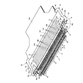
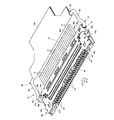
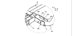
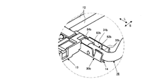
- FIG. 4 is an enlarged perspective view showing the inside of a circle C1 shown in FIG. 3 in an enlarged manner. It is a perspective view which shows the state from which the electroconductive cover about the connector apparatus shown by FIG. 1 was removed.
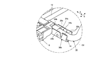
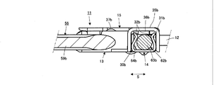
- FIG. 6 is an enlarged perspective view showing the inside of a circle C2 shown in FIG. 5 in an enlarged manner.
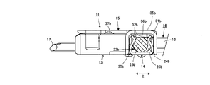
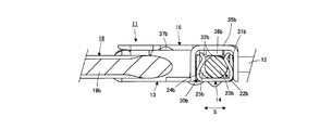
- FIG. 2 is a cross-sectional view showing a cross section taken along line AA in FIG. 1.
- FIG. 3 is a cross-sectional view showing a cross section taken along line BB in FIG. 2.
- FIG.9 and FIG.10 It is a perspective view which shows the operation lever with which the other example of the connector apparatus which concerns on this invention is equipped alone. It is an expansion perspective view which expands and shows the inside of the circle C3 shown by FIG. It is an expansion perspective view which expands and shows a part of other example of the connector device concerning the present invention. It is sectional drawing which shows one cross section in the other example of the connector apparatus which concerns on this invention. It is sectional drawing which shows one cross section in the other example of the connector apparatus which concerns on this invention. It is a perspective view which shows the operation lever with which the further another example of the connector apparatus which concerns on this invention is provided alone.
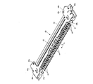
- FIG. 1 and 2 show an example (Example 1) of a connector device according to the present invention together with a plurality of cables connected thereto.
- the connector device 11 includes, for example, an electric circuit provided on a substrate to be a solid printed wiring board, for example, with a plurality of coaxial cables 12 electrically connected thereto. It is supposed to be used as a cable or the like side connector device that fits into a mating side connector device that is a board side connector device that is attached by electrical connection with a component.
- the connector apparatus 11 shall cover the outer surface part of the insulation housing 13 and the insulation housing 13 formed with insulation materials, such as a synthetic resin, and the outer surface part of the insulation housing 13 for the countermeasure against electromagnetic wave noise from the exterior, for example, each is elastic
- the insulating housing 13 has a longitudinal direction (a direction indicated by an arrow L), which is in a fitting state with a fitting recess provided in the mating connector device (board-side connector device), and is described below. , Referred to as the L direction).
- the insulating housing 13 includes a plurality of conductive contacts 18 formed by bending a metal material having elasticity, for example, and a part of each of the conductive contacts 18 is arranged in the L-direction on the fitting protrusions 17. It is supposed to be arranged.
- a portion of each of the plurality of conductive contacts 18 arranged on the fitting convex portion 17 is arranged such that when the fitting convex portion 17 is in a fitting state with a fitting concave portion provided in the counterpart connector device, A plurality of conductive contacts disposed in the connector device and electrically connected to the substrate are contact-connected to each other, whereby the plurality of conductive contacts 18 are respectively connected to the plurality of conductive contacts in the mating connector device. Will be connected.
- a signal conductor of a corresponding one of the plurality of coaxial cables 12 is connected to each of the plurality of conductive contacts 18.
- Each of the plurality of coaxial cables 12 has a signal conductor connected to the conductive contact 18 and a ground conductor connected to the conductive shell 14 and the conductive cover 15 to be electrically connected to the connector device 11.
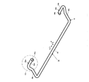
- the operation lever 16 includes a main body portion 21 formed by connecting a pair of bent arm portions 19 a and 19 b by a connecting portion 20 extending in the L direction, and a main body portion 21. And a pair of end portions 22a and 22b respectively connected to both ends.
- the end portion 22a is connected to a bent arm portion 19a that forms one end of the main body portion 21, and has an extended portion 23a that is bent and connected to the bent arm portion 19a, and a tip portion 24a that is further connected to the extended portion 23a. And extending in the direction along the L direction.
- end portion 22b is connected to a bent arm portion 19b that forms the other end of the main body portion 21, and an extended portion 23b that bends and continues to the bent arm portion 19b, and a distal end portion 24b that further continues to the extended portion 23b. And extends in the direction along the L direction.
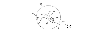
- FIG. 4 which is an enlarged view of the circle C1 surrounding the end portion 22a of the operation lever 16 shown in FIG. 3, the extended portion 23a and the front end portion 24a of the end portion 22a of the operation lever 16 are The portion 24a is parallel-displaced in the direction perpendicular to the central axis direction of the extended portion 23a with respect to the extended portion 23a, and a step portion 25a is formed at the boundary with the extended portion 23a. Accordingly, the central axis direction of the distal end portion 24a is parallel to the central axial direction of the elongated portion 23a, and the central axial direction of the elongated portion 23a is along the L direction. It becomes the direction along. And as FIG.
- tip part 24a are the virtual of the front-end
- the central axis line 27a is placed in a relationship of parallel displacement in a direction orthogonal to the L direction (the direction indicated by the arrow S, hereinafter referred to as the S direction).
- the extended portion 23b and the distal end portion 24b of the end portion 22b of the operation lever 16 are such that the distal end portion 24b is displaced in parallel with the extended portion 23b in a direction orthogonal to the central axis direction of the extended portion 23b.
- a step portion 25b is formed at the boundary with the elongated portion 23b.
- the central axis direction of the distal end portion 24b is parallel to the central axial direction of the elongated portion 23b, and the central axial direction of the elongated portion 23b is along the L direction. It becomes the direction along.
- the extension portion 23b and the tip portion 24b are not shown, but the virtual center of the tip portion 24b extending along the L direction is also the same as the virtual center axis of the extension portion 23b extending along the L direction.
- the axis line is in a relationship of parallel displacement in the S direction orthogonal to the L direction.
- the operation lever 16 configured as described above has a pair of end portions 22a and 22b, that is, an extension portion 23a and a tip portion 24a as described above.
- the end portion 22b having the end portion 22a and the extending portion 23b and the tip end portion 24b are rotatably supported by both end portions of the conductive shell 14 in the L direction.
- the end portions 22a and 22b extend in a direction from the end portion of the insulating housing 13 toward the center portion in the direction along the L direction, and the tip portions 24a and 24b are opposed to each other.
- the operation lever 16 is rotatable with respect to the insulating housing 13.
- an operation tag 16 ⁇ / b> A for facilitating the rotation operation of the operation lever 16 is attached to the connecting portion 20 that forms the main body portion 21 of the operation lever 16.
- the conductive shell 14 partially covers the lower outer surface (hereinafter referred to as the bottom surface) of the insulating housing 13 in FIGS. 1 and 2, and the conductive cover 15 is provided in the insulating housing 13.
- the outer surface (hereinafter referred to as the upper surface) on the upper side is partially covered.
- both ends in the L direction of the conductive shell 14 are A pair of end portions 22a and 22b of the operating lever 16, that is, an end portion 22a having an extension portion 23a and a tip portion 24a and an end portion 22b having an extension portion 23b and a tip portion 24b are rotatable.
- a pair of support mechanisms 30a and 30b to support is provided.
- the signal conductor 12A is connected to the conductive contact 18, and the ground conductor 12B is connected to the ground common conductor 13X.
- the grounding common conductor 13 ⁇ / b> X is contact-connected to the conductive shell 14 and the conductive cover 15.
- the support mechanism 30 a includes an elastic holding portion 31 a that holds an end portion 22 a having an extended portion 23 a and a tip end portion 24 a of the operation lever 16, and the support mechanism 30 b includes the operation lever 16.
- An elastic holding portion 31b is provided to hold the end portion 22b having the extended portion 23b and the tip portion 24b.
- Each of the pair of end portions 22a and 22b of the operation lever 16 extends in a direction along the L direction from the end portion of the insulating housing 13 toward the center portion, and thus supports the end portions 22a and 22b.
- Each of the holding portions 31a and 31b provided in the mechanisms 30a and 30b also extends in the L direction.
- the operation lever 16 is rotated with respect to the insulating housing 13 around the end portions 22a and 22b held by the holding portions 31a and 31b, respectively, and the main body portion 21 as shown in FIG. Is located on the side of the plurality of coaxial cables 12 that are electrically connected to the connector device 11, and the body portion 21 as shown in FIG.
- the position to be arranged on the convex portion 17 side is selectively taken.
- the support mechanism 30a includes a locking portion 32a that engages with the step portion 25a of the end portion 22a having the extended portion 23a and the distal end portion 24a of the operation lever 16 to lock the end portion 22a.
- the support mechanism 30b is engaged with the step portion 25b of the end portion 22b having the extended portion 23b and the distal end portion 24b of the operation lever 16 to lock the end portion 22b.
- a locking portion 32b is provided.
- FIG. 6 which expands and shows the inside of the circle C2 surrounding the part including the support mechanism 30b provided at the end 22b of the operation lever 16 and the one end of the conductive shell 14 shown in FIG.
- the holding portion 31b provided in 30b extends in the L direction to form a groove-like portion in which the extended portion 23b, the tip portion 24b, and the step portion 25b of the end portion 22b of the operation lever 16 are rotatably arranged.
- the locking portion 32b provided in the support mechanism 30b forms a pair of bent wall-like portions that face each other across the extended portion 23b of the end portion 22b of the operation lever 16 in the S direction. .
- the groove-shaped portion formed by the holding portion 31b provided in the support mechanism 30b regulates the position in the S direction with respect to the portion including the extended portion 23b, the tip portion 24b, and the step portion 25b in the end portion 22b disposed thereon. Further, the bent wall-shaped portion formed by the locking portion 32b provided in the support mechanism 30b is in a state in which the end surface on the holding portion 31b side in the L direction is engaged with the step portion 25b in the end portion 22b.
- the holding portion 31a provided in the support mechanism 30a extends in the L direction, and a portion including the extended portion 23a, the tip portion 24a, and the step portion 25a in the end portion 22a of the operation lever 16 is rotatably disposed.
- the locking portion 32a provided in the support mechanism 30a forms a groove-like portion, and a pair of bent wall-like portions facing each other across the extended portion 23a of the end portion 22a of the operation lever 16 in the S direction. Is forming.
- the groove-shaped portion formed by the holding portion 31a provided in the support mechanism 30a regulates the position in the S direction with respect to the portion including the extended portion 23a, the tip portion 24a, and the step portion 25a in the end portion 22a disposed thereon.
- the bent wall-shaped portion formed by the locking portion 32a provided in the support mechanism 30a is in a state where the end surface on the holding portion 31a side in the L direction is engaged with the step portion 25a in the end portion 22a.
- both end portions 35 a and 35 b in the L direction are in the L direction in the conductive shell 14.
- the support mechanisms 30a and 30b which are provided at both ends of the control lever 16 and rotatably support the pair of end portions 22a and 22b of the operation lever 16, respectively.
- holding piece portions 36a and 36b are respectively provided at both ends 35a and 35b in the L direction of the conductive cover 15, and these holding pieces 36a and 36b have both ends 35a and 35b supported by the support mechanism 30a.
- 30b respectively contact the end portions 22a and 22b of the operation lever 16 supported by the support mechanisms 30a and 30b, respectively, and serve to suppress them.
- both end portions 35a and 35b of the conductive cover 15 cover the support mechanisms 30a and 30b, respectively, and thereby the inside of each of the holding portion 31a and the locking portion 32a included in the support mechanism 30a and the support mechanism 30b. Dust and foreign matter are prevented from entering the holding portion 31b and the locking portion 32b.
- the fitting convex portion 17 of the insulating housing 13 Engagement protrusions 37a and 37b that engage with engagement holes provided in the conductive shell of the mating connector device are provided.
- Each of the engagement protrusions 37a and 37b is formed on an elastic piece formed by a part of the conductive cover 15, and engages with and engages with an engagement hole provided in the conductive shell of the mating connector device. The separation from the joint hole is performed with the elastic deformation of the elastic piece.
- the holding portion 31a having elasticity provided in the support mechanism 30a provided at the end portion of the conductive shell 14 is connected to the end of the operation lever 16 disposed in the groove portion formed by the holding portion 31a.
- the extended portion 23a and the distal end portion 24a forming the portion 22a are held in a state that allows the parallel displacement direction of the distal end portion 24a to the extended portion 23a to be changed according to the turning operation of the operation lever 16.
- the holding portion 31b having elasticity provided in the support mechanism 30b provided at the end portion of the conductive shell 14 forms the end portion 22b of the operation lever 16 arranged in the groove-like portion formed by the holding portion 31b.
- the extending portion 23b and the distal end portion 24b to be held are held in a state that allows the parallel displacement direction of the distal end portion 24b to the elongated portion 23b to be changed according to the turning operation of the operation lever 16.
- the operation lever 16 is rotated with respect to the insulating housing 13, and the main body portion 21 is arranged on the side of the plurality of coaxial cables 12 electrically connected to the connector device 11.
- the support mechanism 30b provided at the end of the conductive shell 14, as shown in FIG. 7 showing a cross section along the line AA shown in FIG.
- the extension portion 23b and the tip portion 24b forming the end portion 22b of the operation lever 16 held by the holding portion 31b are within the groove-like portion formed by the holding portion 31b. It is put in a state of being displaced parallel to the plurality of coaxial cables 12 in the direction.
- the extended portion 23b is arranged on the fitting convex portion 17 side provided in the insulating housing 13 in the S direction, and the tip portion 24b has a plurality of coaxial portions in the S direction. It will be arranged on the cable 12 side.
- the end portion 22b of the operation lever 16 is displaced in the L direction in the direction from the center portion of the insulating housing 13 toward the end portion, that is, the outer side of the insulating housing 13 is displaced.
- the locking portion 32b provided in the support mechanism 30b is moved to the holding portion 31b side in the L direction.
- the step portion 25b is engaged by engaging with a step portion 25b formed by the tip portion 24b of the end portion 22b. This reliably prevents the end 22b of the operation lever 16 from being removed from the support mechanism 30b.
- the holding portion 31a also forms the extended portion 23a and the tip portion 24a that form the end portion 22a of the operation lever 16 held by the holding portion 31a.
- the distal end portion 24a is placed in a state of being displaced parallel to the plurality of coaxial cables 12 in the S direction with respect to the elongated portion 23a.
- the extended portion 23a is arranged on the fitting convex portion 17 side provided in the insulating housing 13 in the S direction
- the tip portion 24a has a plurality of coaxial portions in the S direction. It will be arranged on the cable 12 side.
- the end portion 22a of the operation lever 16 is displaced in the L direction in the direction from the center portion to the end portion of the insulating housing 13, that is, the outer direction of the insulating housing 13 is displaced.
- the locking portion 32a provided in the support mechanism 30a is moved to the holding portion 31a side in the L direction.
- the step portion 25a is engaged by engaging with the step portion 25a formed by the tip portion 24a of the end portion 22a. This reliably prevents the end 22a of the operation lever 16 from being detached from the support mechanism 30a.
- the operation lever 16 is rotated with respect to the insulating housing 13, and the main body portion 21 is arranged on the fitting convex portion 17 side provided in the insulating housing 13.
- the supporting mechanism 30b provided at the end of the conductive shell 14, as shown in FIG. 8 showing a cross section along the line BB shown in FIG.
- the extended portion 23b and the distal end portion 24b forming the end portion 22b of the operation lever 16 held by 31b are insulated in the S direction from the extended portion 23b in the groove portion formed by the holding portion 31b. It is placed in a state where it is displaced parallel to the fitting convex portion 17 side (the side opposite to the plurality of coaxial cables 12 side) provided in the housing 13.
- the extended portion 23b is arranged on the side of the plurality of coaxial cables 12 in the S direction, and the front end portion 24b is a fitting protrusion provided on the insulating housing 13 in the S direction. It will be arranged on the part 17 side.
- the end portion 22b of the operation lever 16 is displaced in the L direction in the direction from the center portion of the insulating housing 13 toward the end portion, that is, the outer side of the insulating housing 13 is displaced.
- the locking portion 32b provided in the support mechanism 30b is moved to the holding portion 31b side in the L direction.
- the step portion 25b is engaged by engaging with a step portion 25b formed by the tip portion 24b of the end portion 22b. This reliably prevents the end 22b of the operation lever 16 from being removed from the support mechanism 30b.
- the holding portion 31a also forms the extended portion 23a and the tip portion 24a that form the end portion 22a of the operation lever 16 held by the holding portion 31a.
- the distal end portion 24a is displaced in parallel with the extended portion 23a toward the fitting convex portion 17 side (the side opposite to the plurality of coaxial cables 12 side) provided in the insulating housing 13 in the S direction. Smelled.
- the extended portion 23a is arranged on the side of the plurality of coaxial cables 12 in the S direction
- the front end portion 24a is provided on the insulating housing 13 in the S direction. It will be arranged on the part 17 side.
- the end portion 22a of the operation lever 16 is displaced in the L direction in the direction from the center portion to the end portion of the insulating housing 13, that is, the outer direction of the insulating housing 13 is displaced.
- the locking portion 32a provided in the support mechanism 30a is moved to the holding portion 31a side in the L direction.
- the step portion 25a is engaged by engaging with the step portion 25a formed by the tip portion 24a of the end portion 22a. This reliably prevents the end 22a of the operation lever 16 from being detached from the support mechanism 30a.
- the operation lever 16 is located at the position where the main body portion 21 is arranged on the side of the plurality of coaxial cables 12 electrically connected to the connector device 11 as shown in FIG. Even when the main body portion 21 takes a rotational position between the main body portion 21 and the position where the main body portion 21 is disposed on the fitting convex portion 17 side provided in the insulating housing 13, An external force is applied to the end 22a or the end 22b in the direction of L in the direction from the center of the insulating housing 13 toward the end, that is, to the outside of the insulating housing 13, and the end 22a is applied.
- the locking portion 32a provided in the support mechanism 30a is the end on the holding portion 31a side in the L direction. Then, the step portion 25a formed by the tip portion 24a in the end portion 22a is engaged, and the holding piece portion 36a provided at the end portion 35a in the L direction of the conductive cover 15 is engaged with the step portion 25a. Then, the locking portion 32b provided in the support mechanism 30b has the end surface on the holding portion 31b side in the L direction, and the step portion 25b formed by the tip portion 24b in the end portion 22b.
- the holding piece 36b provided at the end portion 35b in the L direction of the conductive cover 15 engages with the step portion 25b to lock the step portion 25b. This reliably prevents the end portion 22a or the end portion 22b of the operation lever 16 from being detached from the support mechanism 30a or the support mechanism 30b.
- FIG. 9 (perspective view) and FIG. 10 (front view) show a board-side connector device 40 that is an example of a mating connector device with which the connector device 11 is fitted.
- the board-side connector device 40 is, for example, in a state where the board-side connector device 40 is attached to a board to be a solid printed wiring board by being electrically connected to an electric circuit component provided on the board.
- the connector device 11 is to be fitted.
- the board-side connector device 40 is configured to cover most of the insulating housing 41 formed of an insulating material such as synthetic resin and the outer surface portion of the insulating housing 41 for countermeasures against electromagnetic noise from the outside.
- a conductive shell 42 formed by bending a metal plate material having elasticity is provided.
- the longitudinal direction of the insulating housing 41 (in the direction indicated by the arrow L ′), which is in a fitted state with the fitting convex portion 17 provided in the connector device 11, Hereinafter, a fitting recess 43 extending in the L ′ direction) is provided.
- the insulating housing 41 is provided with a plurality of conductive contacts 44 formed by bending a metal material having elasticity, for example, arranged in the L ′ direction. Yes.
- One end of each of the plurality of conductive contacts 44 projecting outward from the insulating housing 41 forms a connection terminal connected to a wiring pattern portion provided on a substrate to which the board-side connector device 40 is attached. .
- each of the plurality of conductive contacts 44 is disposed in the fitting recess 43, and when the fitting protrusion 17 of the connector device 11 is in a fitting state with the fitting recess 43, A corresponding one of the plurality of conductive contacts 18 arranged in the connector device 11 is contact-connected.
- the conductive shell 42 is fitted to the fitting recesses 43 provided in the insulating housing 41 with the fitting protrusions 17 provided in the insulating housing 13 of the connector device 11 at both ends 45 a and 45 b in the L ′ direction.
- engagement holes 46a and 46b are provided to engage with the engagement protrusions 37a and 37b provided on the conductive cover 15 of the connector device 11, respectively.
- the conductive shell 42 protrudes from the insulating housing 41 at a position sandwiching the plurality of conductive contacts 44 arranged in an array, and is connected to a ground connection portion provided on a substrate to which the board-side connector device 40 is attached.
- the ground connection terminals 47a and 47b are provided.
- each of the plurality of conductive contacts 44 is connected to a wiring pattern portion provided on a board to which the board-side connector device 40 is attached, and ground connection terminals 47a and 47b are provided.
- the board-side connector device 40 is connected to a ground connection portion provided on a board to which the board-side connector device 40 is attached, and is placed in a state where the board is electrically connected to an electric circuit component provided on the board.
- the connector device 11 and the board-side connector device 40 described above are configured so that the board-side connector device 40 is electrically connected to an electric circuit component provided on a board that is a solid printed wiring board, for example.
- the fitting projection 17 provided on the insulating housing 13 of the connector device 11 is provided on the insulating housing 41 and the conductive shell 42 of the board-side connector device 40 under the state where the electrical connection is made.
- the fitting recess 43 is inserted into the fitting recess 43 with movement along the S direction so that the connector device 11 is fitted to the board-side connector device 40.
- the operation lever 16 provided in the connector device 11 is arranged on the side of the plurality of coaxial cables 12 whose main body portion 21 is electrically connected to the connector device 11 as shown in FIG. It is supposed to take a position to become.
- the fitting convex portion 17 provided in the insulating housing 13 of the connector device 11 is inserted into the fitting concave portion 43 provided in the insulating housing 41 and the conductive shell 42 of the board side connector device 40.
- the engagement protrusions 37a and 37b provided on the conductive cover 15 of the connector device 11 are engaged with the engagement holes 46a and 46a provided on the conductive shell 42 of the board-side connector device 40, respectively. 46b is engaged.
- the conductive cover 15 and the conductive shell 42 are connected in contact with each other, and the fitting state of the fitting convex portion 17 in the connector device 11 with the fitting concave portion 43 in the board-side connector device 40 is maintained. It is.
- the fitting convex portion 17 provided in the insulating housing 13 of the connector device 11 is inserted into the fitting concave portion 43 provided in the insulating housing 41 and the conductive shell 42 of the board side connector device 40 to be fitted.
- the connector 21 is rotated to a position where it is disposed on the side of the fitting convex portion 17 provided on the insulating housing 13 in the connector device 11, and takes the state shown in FIG.
- the extended portion 23b and the distal end portion 24b forming the 16 end portions 22b are arranged on the plurality of coaxial cables 12 side in the S direction in the groove-shaped portion formed by the holding portion 31b, and the distal end portion 24b Is arranged on the side of the fitting convex portion 17 provided in the insulating housing 13 in the S direction, and in the support mechanism 30a provided at the end of the conductive shell 14 of the connector device 11, the support mechanism 30a
- the extended portion 23a is disposed on the side of the plurality of coaxial cables 12 in the S direction
- the distal end portion 24a is disposed on the fitting convex portion 17 side provided in the insulating housing 13 in the S direction. Will be.
- the end portions 22a and 22b of the operation lever 16 are bent from the elastic holding portions 31a and 31b provided in the support mechanisms 30a and 30b, respectively.
- the main body portion 21 formed by 19b and the connecting portion 20 receives an urging force to move the main body portion 21 toward the plurality of coaxial cables 12 electrically connected to the connector device 11, and transmits the urging force to the operation lever 16. It will be. That is, the extended portion 23a and the distal end portion 24a forming the end 22a of the operation lever 16 and the extended portion 23b and the distal end portion 24b forming the end 22b of the operation lever 16 are supported by the support mechanisms 30a and 30b, respectively.
- the main body portion 21 is electrically connected to the connector device 11 by the operating lever 16 in which the bent arm portions 19a and 19b forming the main body portion 21 are engaged with the elastic engagement portions 48a and 48b, respectively.
- An urging force to be moved toward the plurality of coaxial cables 12 is applied.
- the urging force exerted on the operation lever 16 by the end portions 22a and 22b of the operation lever 16 is such that the bent arm portions 19a and 19b forming the main body portion 21 are provided on the conductive shell 42 of the board side connector device 40.
- the operating lever 16 that is to be engaged with the joint portions 48a and 48b acts as a biasing force in a direction in which the main body portion 21 is pressed against the board-side connector device 40, respectively. Accordingly, the extended portion 23a and the distal end portion 24a forming the end 22a of the operating lever 16 and the extended portion 23b and the distal end portion 24b forming the end 22b of the operating lever 16 are supported by the support mechanisms 30a and 30b, respectively.
- the bending arm portions 19a and 19b forming the main body portion 21 are engaged with the elastic engagement portions 48a and 48b provided on the conductive shell 42 of the board-side connector device 40, respectively.
- the bending arm portions 19a and 19b forming the main body portion 21 are respectively engaged with the elastic engagement portions 48a and 48b provided on the conductive shell 42 of the board-side connector device 40.
- 16 is a state in which a biasing force in a direction of pressing the main body portion 21 against the board-side connector device 40 is applied, so that a gap is formed between the main body portion 21 and the board-side connector device 40 so that the body side 21 is “shaking”. Will surely be avoided.
- the end 22a of the operation lever 16 is moved in the direction L from the center of the insulating housing 13 toward the end in the L direction.
- the support mechanism 30a is provided.
- the locking portion 32a has the end surface on the holding portion 31a side in the L direction and engages with the step portion 25a formed by the tip portion 24a of the end portion 22a to lock the step portion 25a, thereby operating
- the end portion 22a of the lever 16 is reliably prevented from being detached from the support mechanism 30a, and the end portion 22b of the lever 16 is connected to the operation lever 16 in the L direction. Displacement in the direction from the center of the jing 13 toward the end, that is, an external force that causes displacement of the insulating housing 13 outward is applied, and the end 22b is directed from the center of the insulating housing 13 toward the end.
- the locking portion 32b provided in the support mechanism 30b engages with the step portion 25b formed by the tip portion 24b of the end portion 22b with the end surface on the holding portion 31b side in the L direction.
- the step portion 25b is locked, thereby reliably preventing the end portion 22b of the operation lever 16 from being detached from the support mechanism 30b.
- the entire connector device 11 is moved away from the board-side connector device 40, and the fitting convex portion 17 provided on the insulating housing 13 of the connector device 11 includes the insulating housing 41 of the board-side connector device 40 and It is removed from the fitting recess 43 provided in the conductive shell 42.
- the support mechanism 30a provided at one end portion of the conductive shell 14 is configured to include a holding portion 31a that forms a groove-shaped portion, and the other end of the conductive shell 14 is provided.
- the support mechanism 30b provided in the portion is configured to include a holding portion 31b that forms a groove-like portion, but the support mechanisms 30a and 30b are respectively the end portions 22a and 22b of the operation lever 16.
- Various other specific configurations can be adopted as a configuration for supporting and energizing the lens in a rotatable manner.
- FIG. 13 shows a single operation lever 56 provided in another example (Example 2) of the connector device according to the present invention.
- the second embodiment including the operation lever 56 shown in FIG. 13 is configured in the same manner as the first embodiment (connector device 11) except for the operation lever 56. Therefore, with respect to the parts configured in the same way as in the first embodiment in the second embodiment, the entire detailed description is omitted, and the parts according to the necessity of the description are denoted by the reference numerals given to the corresponding parts in the first embodiment. Are illustrated and described as having the same reference numerals.
- a plurality of coaxial cables similar to the plurality of coaxial cables 12 that are electrically connected to the first embodiment are connected, and the plurality of coaxial cables 12 are electrically connected to the first embodiment.
- the board-side connector device is a mating connector device similar to the board-side connector device 40 which is the mating connector device to which the first embodiment is fitted.
- the first embodiment is fitted in the same manner as the first embodiment is fitted to the board-side connector device 40.
- a pair of bent arm portions 59a and 59b extend in the L direction (the longitudinal direction of the insulating housing in the second embodiment, which is indicated by the arrow L). And a pair of end portions 62 a and 62 b respectively connected to both ends of the main body portion 61.
- the end portion 62a is connected to a bent arm portion 59a that forms one end of the main body portion 61, and has an extended portion 63a that is bent and connected to the bent arm portion 59a, and a distal end portion 64a that is further connected to the extended portion 63a.
- it extends in the direction along the L direction as a whole.
- end portion 62b is connected to a bent arm portion 59b that forms the other end of the main body portion 61, an extended portion 63b that is bent and connected to the bent arm portion 59b, and a distal end portion 64b that is further connected to the extended portion 63b. And extends in the direction along the L direction as a whole.
- FIG. 14 which is an enlarged view of a circle C3 surrounding the end portion 62a of the operation lever 56 shown in FIG. 13, the extended portion 63a and the distal end portion 64a of the end portion 62a of the operation lever 56 are The portion 64a is bent and protrudes in a direction perpendicular to the central axis direction of the extended portion 63a with respect to the extended portion 63a. Accordingly, the central axis direction of the distal end portion 64a is orthogonal to the central axial direction of the elongated portion 63a, and the central axial direction of the elongated portion 63a is the direction along the L direction. (The direction perpendicular to the L direction and indicated by the arrow S). And as FIG.
- tip part 64a are the virtual center axis line 66a of the front-end
- tip part 64a have the relationship from which the virtual center axis line of the extension part 63a extended along the L direction and the virtual center axis line of the front-end
- the operation lever 56 configured as described above has a pair of end portions 62a and 62b, that is, the extension portion 63a and the tip end portion 64a as described above, similarly to the operation lever 16 in the first embodiment.
- the end portion 62b having the end portion 62a and the extended portion 63b and the tip end portion 64b is rotatably supported by the support mechanisms 30a and 30b provided at both ends in the L direction of the conductive shell 14. .
- Each of the end portions 62a and 62b extends in a direction from the end portion of the insulating housing 13 toward the central portion in the direction along the L direction as a whole, whereby the operation lever 56 is attached to the insulating housing 13. On the other hand, it can be rotated.
- an operation tag for facilitating the rotation operation of the operation lever 56 is attached to the connecting portion 60 forming the main body 61 of the operation lever 56.
- the holding portion 31 b provided in the support mechanism 30 b provided at the end portion of the conductive shell 14 extends in the L direction and forms an end portion 62 b of the operation lever 56.
- a groove portion in which the tip end portion 64b is rotatably arranged is formed, and the locking portion 32b provided in the support mechanism 30b has an extended portion 63b in the end portion 62b of the operation lever 56 in the S direction.
- a pair of bent wall-like portions opposing each other are formed.
- the groove-like portion formed by the holding portion 31b provided in the support mechanism 30b regulates the position in the S direction with respect to the extended portion 63b and the tip portion 64b that form the end portion 62b disposed thereon.
- the bent wall-shaped portion formed by the locking portion 32b provided in the support mechanism 30b is in a state in which the end surface on the holding portion 31b side in the L direction is engaged with the tip portion 64b in the end portion 62b.
- the holding portion 31a provided in the support mechanism 30a provided at the end portion of the conductive shell 14 has an extension portion 63a and a tip portion 64a that extend in the L direction to form the end portion 62a of the operation lever 56.
- a groove-like portion that is movably disposed is formed, and the locking portion 32a provided in the support mechanism 30a is opposed to each other across the extended portion 63a of the end portion 62a of the operation lever 56 in the S direction.
- a pair of bent wall portions are formed.
- the groove-like portion formed by the holding portion 31a provided in the support mechanism 30a regulates the position in the S direction with respect to the extended portion 63a and the tip portion 64a that form the end portion 62a disposed thereon.
- the bent wall-shaped portion formed by the locking portion 32a provided in the support mechanism 30a is in a state where the end surface on the holding portion 31a side in the L direction is engaged with the tip end portion 64a in the end portion 62a.
- the holding portion 31a having elasticity provided in the support mechanism 30a provided at the end portion of the conductive shell 14 is the end of the operation lever 56 disposed in the groove-like portion formed by the holding portion 31a.
- the extended portion 63a and the distal end portion 64a forming the portion 62a are held in a state that allows the bending direction of the distal end portion 64a from the extended portion 63a to be changed according to the turning operation of the operation lever 56.
- the holding portion 31b having elasticity provided in the support mechanism 30b provided at the end portion of the conductive shell 14 forms the end portion 62b of the operation lever 56 disposed in the groove-like portion formed by the holding portion 31b.
- the extending portion 63b and the distal end portion 64b to be held are held in a state that allows the bending direction of the distal end portion 64b from the extended portion 63b to be changed according to the turning operation of the operation lever 56.
- the operation lever 56 is rotated with respect to the insulating housing 13 so that the main body 61 is disposed on the side of the plurality of coaxial cables 12 electrically connected to the connector device 11.
- the support mechanism 30 b provided at the end of the conductive shell 14, the extended portion 63 b that forms the end 62 b of the operation lever 56 held by the holding portion 31 b and
- the distal end portion 64b is bent in the S direction from the elongated portion 63b and protrudes toward the plurality of coaxial cables 12 in the groove-shaped portion formed by the holding portion 31b.
- the extended portion 63b is arranged on the fitting convex portion 17 side provided in the insulating housing 13 in the S direction, and the tip portion 64b has a plurality of coaxial portions in the S direction. It will be arranged on the cable 12 side.
- the restraining piece 36b provided at the end 35b in the L direction of the conductive cover 15 abuts on the end 62b of the operation lever 56 supported by the support mechanism 30b and serves to restrain them. Fulfill.
- the end 62b of the operating lever 56 is displaced in the direction from the center of the insulating housing 13 toward the end in the L direction, that is, the insulating housing 13 is displaced outward.
- the locking portion 32b provided in the support mechanism 30b is moved to the holding portion 31b side in the L direction.
- the front end portion 64b of the end portion 62b is engaged with and engaged with the front end portion 64b. This reliably prevents the end 62b of the operation lever 56 from being removed from the support mechanism 30b.
- the holding portion 31a also forms the extended portion 63a and the tip portion 64a that form the end portion 62a of the operation lever 56 held by the holding portion 31a.
- the distal end portion 64a is bent and protrudes in the S direction from the extended portion 63a and is placed in a state facing the plurality of coaxial cables 12 side.
- the extended part 63a is arranged on the fitting convex part 17 side provided in the insulating housing 13 in the S direction, and the tip part 64a has a plurality of coaxial parts in the S direction. It will be arranged on the cable 12 side.
- the restraining piece 36a provided at the end 35a in the L direction of the conductive cover 15 abuts on the end 62a of the operation lever 56 supported by the support mechanism 30a and plays a role of restraining them. Fulfill.
- the end 62a of the operating lever 56 is displaced in the direction from the center to the end of the insulating housing 13 in the L direction, that is, the insulating housing 13 is displaced outward.
- the locking portion 32a provided in the support mechanism 30a is moved to the holding portion 31a side in the L direction. With the end face, it engages with the tip end portion 64a of the end portion 62a and locks the tip end portion 64a. This reliably prevents the end 62a of the operation lever 56 from being detached from the support mechanism 30a.
- the operation lever 56 is rotated with respect to the insulating housing 13 so that the main body portion 61 is positioned on the fitting convex portion 17 side provided in the insulating housing 13.
- the extended portion 63b and the tip end portion 64b that form the end portion 62b of the operation lever 56 held by the holding portion 31b.
- the tip end portion 64b protrudes from the elongated portion 63b by bending in the S direction, and the fitting convex portion 17 side provided on the insulating housing 13 (the side of the plurality of coaxial cables 12) On the opposite side).
- the extended portion 63b is arranged on the side of the plurality of coaxial cables 12 in the S direction, and the tip portion 64b is a fitting protrusion provided on the insulating housing 13 in the S direction. It will be arranged on the part 17 side.
- the restraining piece 36b provided at the end 35b in the L direction of the conductive cover 15 abuts against the end 62b of the operation lever 56 supported by the support mechanism 30b and restrains them. Play a role.
- the end 62b of the operating lever 56 is displaced in the direction from the center of the insulating housing 13 toward the end in the L direction, that is, the insulating housing 13 is displaced outward.
- the locking portion 32b provided in the support mechanism 30b is moved to the holding portion 31b side in the L direction.
- the front end portion 64b of the end portion 62b is engaged with and engaged with the front end portion 64b. This reliably prevents the end 62b of the operation lever 56 from being removed from the support mechanism 30b.
- the holding portion 31a also forms the extended portion 63a and the tip portion 64a that form the end portion 62a of the operation lever 56 held by the holding portion 31a.
- the distal end portion 64a protrudes from the extended portion 63a by bending in the S direction, and faces toward the fitting convex portion 17 side provided on the insulating housing 13 (the side opposite to the plurality of coaxial cable 12 sides). I was in a state of being.
- the extended portion 63a is arranged on the side of the plurality of coaxial cables 12 in the S direction, and the leading end portion 64a is provided on the insulating housing 13 in the S direction. It will be arranged on the part 17 side.
- the restraining piece 36a provided at the end 35a in the L direction of the conductive cover 15 abuts against the end 62a of the operation lever 56 supported by the support mechanism 30a and restrains them. Play a role.
- the end 62a of the operating lever 56 is displaced in the direction from the center to the end of the insulating housing 13 in the L direction, that is, the insulating housing 13 is displaced outward.
- the locking portion 32a provided in the support mechanism 30a is moved to the holding portion 31a side in the L direction. With the end face, it engages with the tip end portion 64a of the end portion 62a and locks the tip end portion 64a. This reliably prevents the end 62a of the operation lever 56 from being detached from the support mechanism 30a.
- the operating lever 56 is disposed at the position where the main body 61 is disposed on the plurality of coaxial cables 12 side, and the main body 61 is disposed on the fitting convex portion 17 provided on the insulating housing 13. Even when the rotation position is taken between the operation lever 56, the end 62a or the end 62b of the operation lever 56 is moved in the L direction from the center of the insulating housing 13 toward the end. When an external force that causes displacement, that is, outward displacement of the insulating housing 13 is applied, and the end portion 62a or the end portion 62b is displaced in the direction from the central portion to the end portion of the insulating housing 13, the support mechanism 30a.
- the holding piece 36b provided at the end portion 35b in the L direction of the conductive cover 15 engages with the tip portion 64a of the end portion 62a or the tip portion 64b of the end portion 62b, so that the tip portion 64a or the tip portion 64b. Lock. This reliably prevents the end 62a or end 62b of the operation lever 56 from being detached from the support mechanism 30a or the support mechanism 30b.
- the board-side connector device 40 is electrically connected to an electric circuit component provided on a board to be a solid printed wiring board, for example.
- the fitting convex portion 17 provided in the insulating housing 13 in the state of being attached to the fitting concave portion 43 provided in the insulating housing 41 and the conductive shell 42 of the board-side connector device 40 in the S direction. Is inserted into the board side connector device 40, thereby being fitted into the board side connector device 40.
- the operation lever 56 provided in the second embodiment takes a position where the main body 61 is arranged on the plurality of coaxial cables 12 side.
- the fitting convex portion 17 provided in the insulating housing 13 is inserted into the fitting concave portion 43 provided in the insulating housing 41 and the conductive shell 42 of the board-side connector device 40 and is in a state of fitting.
- the operation lever 56 is disposed on the fitting convex portion 17 side provided on the insulating housing 13 from the position where the main body portion 61 is disposed on the plurality of coaxial cables 12 side. Is rotated to a position.
- the operation lever 56 When the operation lever 56 is located at a position where the main body 61 is disposed on the side of the fitting convex portion 17 provided on the insulating housing 13, the bent arm portions 59a and 59b of the operation lever 56 are provided.
- the elastic engagement portions 48a and 48b provided on the conductive shell 42 of the board-side connector device 40 are respectively engaged with each other over the protruding portions. Thereby, the operation lever 56 is positioned with respect to the board-side connector device 40.
- the operation lever 56 When the bent arm portions 59a and 59b of the operation lever 56 are engaged with the elastic engagement portions 48a and 48b provided on the conductive shell 42 of the board-side connector device 40, respectively, the operation lever 56 is The main body portion 61 is placed in a state where the main body portion 61 is disposed on the fitting convex portion 17 side provided in the insulating housing 13. Therefore, in the support mechanism 30a provided at the end portion of the conductive shell 14, the extension portion 63a and the tip end portion 64a that form the end portion 62a of the operation lever 56 held by the holding portion 31a provided in the support mechanism 30a are provided.
- the extended portion 63a is disposed on the side of the plurality of coaxial cables 12 in the S direction, and the fitting convex portion 17 provided with the distal end portion 64a on the insulating housing 13 in the S direction.
- the end 62b of the operation lever 56 held by the holding portion 31b provided in the support mechanism 30b is formed in the support mechanism 30b provided at the end of the conductive shell 14, the end 62b of the operation lever 56 held by the holding portion 31b provided in the support mechanism 30b is formed.
- the extending portion 63b and the distal end portion 64b are within the groove-shaped portion formed by the holding portion 31b, and the extending portion 63b is a plurality of coaxial cables in the S direction. Together arranged on 12 side, the tip portion 64b is to be disposed in the fitting projection 17 side provided in the insulating housing 13 in the S direction.
- the end portions 62a and 62b of the operation lever 56 are bent from the elastic holding portions 31a and 31b provided in the support mechanisms 30a and 30b, respectively.
- the main body portion 61 formed by 59b and the connecting portion 60 receives an urging force to move the main body portion 61 toward the plurality of coaxial cables 12 electrically connected to the connector device 11, and transmits the urging force to the operation lever 56. It will be. That is, the extended portion 63a and the distal end portion 64a forming the end portion 62a of the operation lever 56 and the extended portion 63b and the distal end portion 64b forming the end portion 62b of the operation lever 56 are supported by the support mechanisms 30a and 30b, respectively.
- the main body 61 is electrically connected to the connector device 11 by the operating lever 56 in which the bent arm portions 59a and 59b forming the main body 61 are engaged with the elastic engagement portions 48a and 48b, respectively.
- An urging force to be moved toward the plurality of coaxial cables 12 is applied.
- the urging force exerted on the operation lever 56 by the end portions 62 a and 62 b of the operation lever 56 is such that the bent arm portions 59 a and 59 b forming the main body portion 61 are provided on the conductive shell 42 of the board side connector device 40.
- the operating lever 56 which is to be engaged with the joint portions 48a and 48b, acts as a biasing force in a direction in which the main body portion 61 is pressed against the board-side connector device 40.
- the extended portion 63a and the distal end portion 64a forming the end portion 62a of the operation lever 56 and the extended portion 63b and the distal end portion 64b forming the end portion 62b of the operation lever 56 are supported by the support mechanisms 30a and 30b, respectively. Therefore, the bending arm portions 59a and 59b forming the main body portion 61 are engaged with the elastic levers 48a and 48b provided on the conductive shell 42 of the board-side connector device 40, respectively. This constitutes an urging force applying portion that applies an urging force in a direction in which the main body portion 61 is pressed against the board-side connector device 40.
- the bending arm portions 59a and 59b forming the main body portion 61 are respectively engaged with the elastic engagement portions 48a and 48b provided on the conductive shell 42 of the board-side connector device 40.
- 56 is a state in which a biasing force in a direction of pressing the main body 61 against the board-side connector device 40 is applied, and a gap is formed between the main body 61 and the board-side connector device 40, resulting in “shaking”. Will surely be avoided.
- the end 62a of the operation lever 56 is moved in the direction L from the center of the insulating housing 13 toward the end in the L direction.
- the support mechanism 30a is provided.
- the locking portion 32a has the end surface on the holding portion 31a side in the L direction and engages with the tip end portion 64a of the end portion 62a to lock the tip end portion 64a, thereby the end portion 62a of the operation lever 56.
- the end 62b of the operation lever 56 is connected to the center of the insulating housing 13 in the L direction.
- an external force that causes displacement in the direction from the center to the end that is, outward displacement of the insulating housing 13 is applied, and the end 62b is displaced in the direction from the center to the end of the insulating housing 13.
- the locking portion 32b provided in the support mechanism 30b engages with the tip end portion 64b of the end portion 62b with the end face on the holding portion 31b side in the L direction, thereby locking the tip end portion 64b. Further, the end 62b of the operation lever 56 is reliably prevented from being detached from the support mechanism 30b.
- the operation lever 56 is provided in the insulating housing 13 by taking the position where the main body portion 61 is disposed on the fitting convex portion 17 side provided in the insulating housing 13.
- the fitting state of the fitting projection 17 with the insulating housing 41 of the board-side connector device 40 and the fitting recess 43 provided in the conductive shell 42 is more stably and reliably maintained. .
- the operation lever 56 is operated.
- the bent arm portions 59a and 59b forming the main body portion 61 are turned over the protruding portions of the elastic engagement portions 48a and 48b provided on the conductive shell 42 of the board-side connector device 40, respectively.
- the engagement with the elastic engagement portions 48a and 48b is released, and the position where the main body portion 61 is disposed on the plurality of coaxial cables 20 side is taken.
- the entire second embodiment is moved away from the board-side connector device 40, and the fitting protrusions 17 provided on the insulating housing 13 form the insulating housing 41 and the conductive shell 42 of the board-side connector device 40. It is extracted from the fitting recess 43 provided in.
- the support mechanism 30a provided at one end of the conductive shell 14 is configured to include a holding portion 31a that forms a groove-shaped portion, and the other end of the conductive shell 14 is also provided.
- the support mechanism 30b provided in the portion is configured to include a holding portion 31b that forms a groove-shaped portion.
- each of the support mechanisms 30a and 30b includes the end portions 62a and 62b of the operation lever 56, respectively.
- Various other specific configurations can be adopted as a configuration for supporting and energizing the device in a rotatable manner.
- FIG. 18 shows a single operation lever 76 provided in still another example (Example 3) of the connector device according to the present invention.
- the third embodiment including the operation lever 76 shown in FIG. 18 is also configured in the same manner as the first embodiment (connector device 11) except for the operation lever 76. Therefore, with respect to the parts configured in the same way as in the first example in the third example, the overall detailed description is omitted, and the parts according to the necessity of the description are denoted by the reference numerals given to the corresponding parts in the first example. Are illustrated and described as having the same reference numerals. Further, in the third embodiment, a plurality of coaxial cables similar to the plurality of coaxial cables 12 that are electrically connected to the first embodiment are connected, and the plurality of coaxial cables 12 are electrically connected to the first embodiment.
- the third embodiment is a board-side connector device that is a mating connector device similar to the board-side connector device 40 that is the mating connector device to which the first embodiment is fitted.
- the first embodiment is fitted in the same manner as the first embodiment is fitted to the board-side connector device 40.
- a pair of bent arm portions 79a and 79b extend in the L direction (the longitudinal direction of the insulating housing in the third embodiment, which is indicated by the arrow L). And a pair of end portions 82 a and 82 b respectively connected to both ends of the main body portion 81.
- the end portion 82a is connected to a bent arm portion 79a that forms one end of the main body portion 81, and has an extended portion 83a that is bent and connected to the bent arm portion 79a and a distal end portion 84a that is further connected to the extended portion 83a.
- it extends in the direction along the L direction as a whole.
- end portion 82b is connected to a bent arm portion 79b that forms the other end of the main body portion 81, an extended portion 83b that is bent and connected to the bent arm portion 79b, and a distal end portion 84b that is further connected to the extended portion 83b. And extends in the direction along the L direction as a whole.
- FIG. 19 which is an enlarged view of a circle C4 surrounding the end portion 82a of the operation lever 76 shown in FIG. 18, the extension portion 83a and the tip portion 84a of the end portion 82a of the operation lever 76 are The portion 84a is crushed in the V direction (indicated by the arrow V) orthogonal to the central axis direction (L direction) of the extended portion 83a, and is orthogonal to both the L direction and the V direction with respect to the extended portion 83a. Projecting in the S direction (indicated by arrow S). Accordingly, as shown in FIG.
- the extended portion 83a and the distal end portion 84a are composed of an imaginary central axis 86a of the extended portion 83a extending along the L direction and an imaginary central axis 87a of the distal end portion 84a extending along the S direction. Are placed in a relationship that is orthogonal to each other.
- extension portion 83b and the tip portion 84b of the end portion 82b of the operation lever 76 are extended by the tip portion 84b being crushed in the V direction perpendicular to the central axis direction (L direction) of the extension portion 83b.
- the portion 83b protrudes in the S direction orthogonal to both the L direction and the V direction. Therefore, the extension portion 83b and the tip portion 84b are in a relationship in which the virtual center axis of the extension portion 83b extending along the L direction and the virtual center axis of the tip portion 84b extending along the S direction are orthogonal to each other. It is put.
- the operation lever 76 configured in this manner has a pair of end portions 82a and 82b, that is, the extension portion 83a and the tip portion 84a as described above.
- the end portion 82b having the end portion 82a and the extended portion 83b and the tip end portion 84b are rotatably supported by the support mechanisms 30a and 30b provided at both ends of the conductive shell 14 in the L direction.
- Each of the end portions 82a and 82b extends in a direction from the end portion of the insulating housing 13 toward the central portion in the direction along the L direction, so that the operation lever 76 is connected to the insulating housing 13. On the other hand, it can be rotated.
- an operation tag for facilitating the rotation operation of the operation lever 76 is attached to the connecting portion 80 that forms the main body 81 of the operation lever 76.
- the holding portion 31 b provided in the support mechanism 30 b provided at the end portion of the conductive shell 14 extends in the L direction and forms an end portion 82 b of the operation lever 76.
- the tip portion 84b forms a groove-like portion that is rotatably arranged, and the locking portion 32b provided in the support mechanism 30b has an extension portion 83b at the end portion 82b of the operation lever 76 in the S direction.
- a pair of bent wall-like portions opposing each other are formed.
- the groove-like portion formed by the holding portion 31b provided in the support mechanism 30b regulates the position in the S direction with respect to the extended portion 83b and the tip portion 84b that form the end portion 82b disposed thereon.
- the bent wall-shaped portion formed by the locking portion 32b provided in the support mechanism 30b is in a state in which the end surface on the holding portion 31b side in the L direction is engaged with the tip portion 84b in the end portion 82b.
- the holding portion 31a provided in the support mechanism 30a provided at the end portion of the conductive shell 14 has an extension portion 83a and a tip portion 84a that extend in the L direction to form the end portion 82a of the operation lever 76.
- a groove-like portion that is movably disposed is formed, and the locking portion 32a provided in the support mechanism 30a is opposed to each other across the extended portion 83a in the end portion 82a of the operation lever 76 in the S direction.
- a pair of bent wall portions are formed.
- the groove-shaped portion formed by the holding portion 31a provided in the support mechanism 30a regulates the position in the S direction with respect to the elongated portion 83a and the tip portion 84a that form the end portion 82a disposed thereon.
- the bent wall-shaped portion formed by the locking portion 32a provided in the support mechanism 30a is in a state in which the end surface on the holding portion 31a side in the L direction is engaged with the tip portion 84a in the end portion 82a.
- the holding portion 31a having elasticity provided in the support mechanism 30a provided at the end portion of the conductive shell 14 is connected to the end of the operation lever 76 arranged in the groove-shaped portion formed by the holding portion 31a.
- the extending portion 83a and the distal end portion 84a forming the portion 82a are held in a state that allows the protruding direction of the distal end portion 84a from the extended portion 83a to be changed according to the turning operation of the operation lever 76.
- the holding portion 31b having elasticity provided in the support mechanism 30b provided at the end portion of the conductive shell 14 forms the end portion 82b of the operation lever 76 disposed in the groove-shaped portion formed by the holding portion 31b.
- the extending portion 83b and the distal end portion 84b to be held are held in a state that allows the protruding direction of the distal end portion 84b from the extended portion 83b to be changed according to the turning operation of the operation lever 76.
- the operation lever 76 is rotated with respect to the insulating housing 13, and the main body 81 is positioned on the side of the plurality of coaxial cables 12 electrically connected to the connector device 11.
- the support mechanism 30 b provided at the end portion of the conductive shell 14, an extended portion 83 b that forms the end portion 82 b of the operation lever 76 held by the holding portion 31 b and
- the distal end portion 84b is placed in a state where the distal end portion 84b protrudes in the S direction from the elongated portion 83b and faces the plurality of coaxial cables 12 in the groove-shaped portion formed by the holding portion 31b.
- the extended portion 83b is arranged on the fitting convex portion 17 side provided in the insulating housing 13 in the S direction, and the tip portion 84b is a plurality of coaxial portions in the S direction. It will be arranged on the cable 12 side.
- the restraining piece 36b provided at the end 35b in the L direction of the conductive cover 15 abuts on the end 82b of the operation lever 76 supported by the support mechanism 30b, and serves to restrain them. Fulfill.
- the end 82b of the operation lever 76 is displaced in the L direction in the direction from the center to the end of the insulating housing 13, that is, outwardly of the insulating housing 13.
- the locking portion 32b provided in the support mechanism 30b is moved to the holding portion 31b side in the L direction. With the end face, it engages with the tip end portion 84b of the end portion 82b and locks the tip end portion 84b. This reliably prevents the end portion 82b of the operation lever 76 from being removed from the support mechanism 30b.
- the holding portion 31a also forms the extended portion 83a and the tip portion 84a that form the end portion 82a of the operation lever 76 held by the holding portion 31a.
- the tip end portion 84a protrudes from the elongated portion 83a in the S direction and faces the plurality of coaxial cables 12 side.
- the extended portion 83a is arranged on the fitting convex portion 17 side provided in the insulating housing 13 in the S direction, and the tip portion 84a has a plurality of coaxial portions in the S direction. It will be arranged on the cable 12 side.
- the restraining piece 36a provided at the end 35a in the L direction of the conductive cover 15 abuts on the end 82a of the operation lever 76 supported by the support mechanism 30a and plays a role of restraining them. Fulfill.
- the end portion 82a of the operation lever 76 is displaced in the L direction in the direction from the center portion to the end portion of the insulating housing 13, that is, the outer portion of the insulating housing 13 is displaced outward.
- the locking portion 32a provided in the support mechanism 30a is moved to the holding portion 31a side in the L direction. With the end face, it engages with the tip end portion 84a of the end portion 82a to lock the tip end portion 84a. This reliably prevents the end 82a of the operation lever 76 from being removed from the support mechanism 30a.
- the operation lever 76 is rotated with respect to the insulating housing 13 so that the main body 81 is positioned on the fitting convex portion 17 side provided in the insulating housing 13.
- the extension portion 83b and the tip end portion 84b forming the end portion 82b of the operation lever 76 held by the holding portion 31b.
- the tip end portion 84b projects in the S direction from the extended portion 83b, and the fitting convex portion 17 side provided on the insulating housing 13 (what are the plurality of coaxial cable 12 sides? The other side).
- the extended portion 83b is arranged on the side of the plurality of coaxial cables 12 in the S direction, and the tip portion 84b is a fitting protrusion provided on the insulating housing 13 in the S direction. It will be arranged on the part 17 side.
- the end 82b of the operation lever 76 is displaced in the L direction in the direction from the center to the end of the insulating housing 13, that is, outwardly of the insulating housing 13.
- the locking portion 32b provided in the support mechanism 30b is moved to the holding portion 31b side in the L direction. With the end face, it engages with the tip end portion 84b of the end portion 82b and locks the tip end portion 84b. This reliably prevents the end portion 82b of the operation lever 76 from being removed from the support mechanism 30b.
- the holding portion 31a also forms the extended portion 83a and the tip portion 84a that form the end portion 82a of the operation lever 76 held by the holding portion 31a.
- the distal end portion 84a protrudes in the S direction from the extended portion 83a and faces the fitting convex portion 17 side (the side opposite to the plurality of coaxial cables 12 side) provided on the insulating housing 13 Smelled.
- the extension part 83a is arranged on the side of the plurality of coaxial cables 12 in the S direction, and the front end part 84a is provided on the insulating housing 13 in the S direction. It will be arranged on the part 17 side.
- the restraining piece 36a provided at the end 35a in the L direction of the conductive cover 15 abuts against the end 82a of the operation lever 76 supported by the support mechanism 30a and restrains them. Play a role.
- the end portion 82a of the operation lever 76 is displaced in the L direction in the direction from the center portion to the end portion of the insulating housing 13, that is, the outer portion of the insulating housing 13 is displaced outward.
- the locking portion 32a provided in the support mechanism 30a is moved to the holding portion 31a side in the L direction. With the end face, it engages with the tip end portion 84a of the end portion 82a to lock the tip end portion 84a. This reliably prevents the end 82a of the operation lever 76 from being removed from the support mechanism 30a.
- the operating lever 76 is disposed at the position where the main body portion 61 is disposed on the plurality of coaxial cables 12 side, and the main body portion 81 is disposed on the fitting convex portion 17 side provided on the insulating housing 13. Even if the rotation position is taken between the operation lever 76 and the end portion 82a or the end portion 82b of the operation lever 76 in the L direction in the direction from the center portion of the insulating housing 13 toward the end portion.
- an external force that causes displacement that is, outward displacement of the insulating housing 13 is applied and the end portion 82a or the end portion 82b is displaced in the direction from the central portion to the end portion of the insulating housing 13, the support mechanism 30a.
- the holding piece 36b provided at the end portion 35b in the L direction of the conductive cover 15 engages the tip end portion 84a at the end portion 82a or the tip end portion 84b at the end portion 82b, so that the tip end portion 84a or the tip end portion 84b. Lock. This reliably prevents the end portion 82a or end portion 82b of the operation lever 76 from being removed from the support mechanism 30a or the support mechanism 30b.
- the board-side connector device 40 is electrically connected to, for example, an electric circuit component provided on a board to be a solid printed wiring board.
- the fitting convex portion 17 provided in the insulating housing 13 in the state of being attached to the fitting concave portion 43 provided in the insulating housing 41 and the conductive shell 42 of the board-side connector device 40 in the S direction. Is inserted into the board side connector device 40, thereby being fitted into the board side connector device 40.
- the operation lever 76 provided in the third embodiment takes a position where the main body 81 is disposed on the plurality of coaxial cables 12 side.
- the fitting convex portion 17 provided in the insulating housing 13 is inserted into the fitting concave portion 43 provided in the insulating housing 41 and the conductive shell 42 of the board-side connector device 40 and is in a state of fitting.
- the operation lever 76 is disposed on the fitting convex portion 17 side provided on the insulating housing 13 from the position where the main body portion 81 is disposed on the plurality of coaxial cables 12 side. Is rotated to a position.
- the operation lever 76 When the operation lever 76 is located at a position where the main body 81 is disposed on the side of the fitting convex portion 17 provided on the insulating housing 13, the bent arm portions 79a and 79b of the operation lever 76 are provided.
- the elastic engagement portions 48a and 48b provided on the conductive shell 42 of the board-side connector device 40 are respectively engaged with each other over the protruding portions. Thereby, the operation lever 76 is positioned with respect to the board-side connector device 40.
- the operation lever 76 When the bent arm portions 79a and 79b of the operation lever 76 are engaged with the elastic engagement portions 48a and 48b provided on the conductive shell 42 of the board-side connector device 40, respectively, the operation lever 76 is The main body 81 is placed in a state where it will be disposed on the side of the fitting convex portion 17 provided in the insulating housing 13. Therefore, in the support mechanism 30a provided at the end portion of the conductive shell 14, the extension portion 83a and the tip portion 84a that form the end portion 82a of the operation lever 76 held by the holding portion 31a provided in the support mechanism 30a are provided.
- the extension part 83a is arranged on the side of the plurality of coaxial cables 12 in the S direction, and the fitting part 17 provided with the tip part 84a on the insulating housing 13 in the S direction.
- the support mechanism 30b provided at the end portion of the conductive shell 14 the end portion 82b of the operation lever 76 held by the holding portion 31b provided in the support mechanism 30b is formed.
- the extending portion 83b and the distal end portion 84b are within the groove-shaped portion formed by the holding portion 31b, and the extending portion 83b is a plurality of coaxial cables in the S direction. Together arranged on 12 side, the tip portion 84b is to be disposed in the fitting projection 17 side provided in the insulating housing 13 in the S direction.
- the end portions 82a and 82b of the operation lever 76 are bent from the elastic holding portions 31a and 31b provided in the support mechanisms 30a and 30b, respectively, and the bent arm portions 79a and 79b in the operation lever 76 are based on the respective elasticity.
- the main body 81 formed by 79 b and the connecting portion 80 receives an urging force to move the main body 81 toward the plurality of coaxial cables 12 electrically connected to the connector device 11, and transmits the urging force to the operation lever 76. It will be.
- the extended portion 83a and the distal end portion 84a that form the end portion 82a of the operation lever 76 and the extended portion 83b and the distal end portion 84b that form the end portion 82b of the operation lever 76 are supported by the support mechanisms 30a and 30b, respectively.
- the main body 81 is electrically connected to the connector device 11 by the operating lever 76 in which the bent arm portions 79a and 79b forming the main body 81 are engaged with the elastic engagement portions 48a and 48b, respectively.
- An urging force to be moved toward the plurality of coaxial cables 12 is applied.
- the urging force exerted on the operation lever 76 by the end portions 82a and 82b of the operation lever 76 is such that the bent arm portions 79a and 79b forming the main body portion 81 are provided on the conductive shell 42 of the board side connector device 40.
- the operation lever 76 that is to be engaged with the joint portions 48 a and 48 b acts as a biasing force in a direction in which the main body portion 81 is pressed against the board-side connector device 40.
- the extended portion 83a and the distal end portion 84a that form the end portion 82a of the operation lever 76 and the extended portion 83b and the distal end portion 84b that form the end portion 82b of the operation lever 76 are supported by the support mechanisms 30a and 30b, respectively.
- the bending arm portions 79a and 79b forming the main body portion 81 are engaged with the elastic levers 48a and 48b provided on the conductive shell 42 of the board-side connector device 40, respectively.
- the bending arm portions 79a and 79b forming the main body portion 81 are respectively engaged with the elastic engagement portions 48a and 48b provided on the conductive shell 42 of the board-side connector device 40.
- 76 is a state in which a biasing force in the direction of pressing the main body portion 81 against the board-side connector device 40 is applied, so that a gap is formed between the main body portion 81 and the board-side connector device 40 so that the body portion 81 is “shaking”. Will surely be avoided.
- the end 82a of the operation lever 76 is moved in the direction L from the center of the insulating housing 13 toward the end in the L direction.
- the support mechanism 30a is provided.
- the locking portion 32a has the end surface on the holding portion 31a side in the L direction and engages with the tip portion 84a of the end portion 82a to lock the tip portion 84a, thereby the end portion 82a of the operation lever 76.
- the end 82b of the operation lever 76 is connected to the center of the insulating housing 13 in the L direction.
- an external force is applied that causes a displacement in the direction from the center to the end, that is, an outward displacement of the insulating housing 13, and the end 82b is displaced in the direction from the center to the end of the insulating housing 13.
- the locking portion 32b provided in the support mechanism 30b engages with the tip end portion 84b of the end portion 82b with the end surface on the holding portion 31b side in the L direction, thereby locking the tip end portion 84b. Further, the end portion 82b of the operation lever 76 is reliably prevented from being detached from the support mechanism 30b.
- the operation lever 76 is provided in the insulating housing 13 by taking the position where the main body 81 is disposed on the fitting convex portion 17 side provided in the insulating housing 13.
- the fitting state of the fitting projection 17 with the insulating housing 41 of the board-side connector device 40 and the fitting recess 43 provided in the conductive shell 42 is more stably and reliably maintained. .
- the operation lever 76 is used.
- the bent arm portions 79a and 79b forming the main body portion 81 are turned over the protruding portions of the elastic engagement portions 48a and 48b provided on the conductive shell 42 of the board-side connector device 40, respectively.
- the engagement with the elastic engagement portions 48a and 48b is released, and the position where the main body portion 81 is arranged on the plurality of coaxial cables 20 side is taken.
- the entire third embodiment is moved away from the board-side connector device 40, and the fitting protrusions 17 provided on the insulating housing 13 are connected to the insulating housing 41 and the conductive shell 42 of the board-side connector device 40. It is extracted from the fitting recess 43 provided in.
- the support mechanism 30a provided at one end portion of the conductive shell 14 is configured to include the holding portion 31a that forms the groove-shaped portion, and the other end of the conductive shell 14 is also provided.
- the support mechanism 30b provided in the portion is configured to include a holding portion 31b that forms a groove-shaped portion.
- each of the support mechanisms 30a and 30b includes the end portions 82a and 82b of the operation lever 76, respectively.
- Various other specific configurations can be adopted as a configuration for supporting and energizing the device in a rotatable manner.
- the connector device according to the present invention as described above includes a fitting portion that causes a plurality of conductive contacts to be connected to a plurality of conductive contacts arranged in the counterpart connector device, and a counterpart connector device of the fitting portion.
- a fitting portion that causes a plurality of conductive contacts to be connected to a plurality of conductive contacts arranged in the counterpart connector device, and a counterpart connector device of the fitting portion.
- an external force that displaces the end of the operation lever in the direction toward the outside of the insulating housing is provided. Even when acting, it is possible to reliably prevent undesired removal of the end from the conductive shell, and to maintain the operation lever in a state where it can play its original role.
- a state where a gap between the operating lever engaged with the connector device and the mating connector device is formed and the operating lever is “shaking” can be reliably avoided. Those that can be widely applied to a vessel or the like.
Landscapes
- Details Of Connecting Devices For Male And Female Coupling (AREA)
Abstract
Description
Claims (9)
- 相手側コネクタ装置に設けられた第1の嵌合部との嵌合状態におかれる第2の嵌合部が設けられた絶縁ハウジングと、
上記第2の嵌合部に配列配置される部分を有して上記絶縁ハウジングに配され、上記第2の嵌合部が上記第1の嵌合部との嵌合状態におかれるとき、上記相手側コネクタ装置に配された複数の第1の導電コンタクトに接続される複数の第2の導電コンタクトと、
上記絶縁ハウジングを部分的に覆う導電性シェルと、
本体部と該本体部の両端に夫々連結された一対の端部とを有し、該一対の端部が上記導電性シェルに設けられた一対の支持機構により夫々支持されて上記絶縁ハウジングに対して回動可能とされ、上記第2の嵌合部が上記第1の嵌合部との嵌合状態におかれるとき回動操作されて、上記本体部が上記相手側コネクタ装置に係合するものとされる操作レバーと、
を備えて構成され、
上記操作レバーの一対の端部の夫々が、上記本体部に屈曲して連なる伸長部分と該伸長部分に更に連なる先端部分とを有し、全体として上記絶縁ハウジングの端部から中央部に向かう第1の向きをもって伸びるものとされるとともに、上記先端部分が上記伸長部分に対して該伸長部分の中心軸方向に直交する方向に平行変位もしくは突出したものとされ、上記支持機構により支持されたもとで上記第1の向きとは反対の第2の向きをもって変位せしめられるとき、上記先端部分に上記支持機構に備えられた係止部が係合して該支持機構からの抜脱が阻止されることを特徴とするコネクタ装置。 - 上記操作レバーの一対の端部の夫々を形成する上記伸長部分及び上記先端部分が、上記支持機構により支持されたもとで、上記本体部が上記相手側コネクタ装置に係合する状態におかれた上記操作レバーに、上記本体部が上記相手側コネクタ装置に押し付けられることになる方向の付勢力を作用させる、付勢力付与部を成すことを特徴とする請求項1記載のコネクタ装置。
- 上記一対の支持機構の夫々が、上記係止部に加えて、上記操作レバーの一対の端部の夫々を形成する上記伸長部分及び上記先端部分を、上記先端部分の上記伸長部分に対する平行変位の向きもしくは突出の向きを上記操作レバーの回動操作に応じて変化させることを許す状態をもって保持する保持部を備えることを特徴とする請求項2記載のコネクタ装置。
- 上記操作レバーの一対の端部の夫々が、上記先端部分が上記伸長部分に対して該伸長部分の中心軸方向に直交する方向に平行変位したものとされて上記伸長部分との境界に段部を形成するものとされ、上記支持機構により支持されたもとで上記第1の向きとは反対の第2の向きをもって変位せしめられるとき、上記段部に上記支持機構に備えられた係止部が係合して該支持機構からの抜脱が阻止されることを特徴とする、請求項1から請求項3までのいずれかに記載のコネクタ装置。
- 上記操作レバーの一対の端部の夫々が、上記先端部分が上記伸長部分に対して該伸長部分の中心軸方向に直交する方向に屈曲して突出するものとされることを特徴とする請求項1から請求項3までのいずれかに記載のコネクタ装置。
- 上記操作レバーの一対の端部の夫々が、上記先端部分が、上記伸長部分の中心軸方向に直交する第1の方向に押し潰されて、上記伸長部分に対して該伸長部分の中心軸方向及び上記第1の方向の夫々に直交する第2の方向に突出するものとされることを特徴とする請求項1から請求項3までのいずれかに記載のコネクタ装置。
- 上記操作レバーの一対の端部が、上記第1及び第2の向きに沿う方向において相互に対向する位置に配されることを特徴とする請求項1記載のコネクタ装置。
- 上記一対の支持機構が、上記絶縁ハウジングにおける該絶縁ハウジングの長手方向の両端部に対応する上記導電性シェルの両端部に夫々設けられることを特徴とする請求項7記載のコネクタ装置。
- 上記絶縁ハウジングを部分的に覆う導電性カバーを備え、該導電性カバーの一部分が上記導電性シェルに設けられた一対の支持機構の夫々を覆うことを特徴とする請求項1記載のコネクタ装置。
Priority Applications (4)
| Application Number | Priority Date | Filing Date | Title |
|---|---|---|---|
| CN200880131889XA CN102210067B (zh) | 2008-09-09 | 2008-10-27 | 连接器装置 |
| KR1020117003895A KR101138116B1 (ko) | 2008-09-09 | 2008-10-27 | 커넥터 장치 |
| US13/061,686 US8096823B2 (en) | 2008-09-09 | 2008-10-27 | Electrical connector |
| EP08876923.7A EP2325952B1 (en) | 2008-09-09 | 2008-10-27 | Connector device |
Applications Claiming Priority (2)
| Application Number | Priority Date | Filing Date | Title |
|---|---|---|---|
| JP2008230542A JP4515516B2 (ja) | 2008-09-09 | 2008-09-09 | コネクタ装置 |
| JP2008-230542 | 2008-09-09 |
Publications (1)
| Publication Number | Publication Date |
|---|---|
| WO2010029647A1 true WO2010029647A1 (ja) | 2010-03-18 |
Family
ID=42004915
Family Applications (1)
| Application Number | Title | Priority Date | Filing Date |
|---|---|---|---|
| PCT/JP2008/069466 Ceased WO2010029647A1 (ja) | 2008-09-09 | 2008-10-27 | コネクタ装置 |
Country Status (7)
| Country | Link |
|---|---|
| US (1) | US8096823B2 (ja) |
| EP (1) | EP2325952B1 (ja) |
| JP (1) | JP4515516B2 (ja) |
| KR (1) | KR101138116B1 (ja) |
| CN (1) | CN102210067B (ja) |
| TW (1) | TW201012007A (ja) |
| WO (1) | WO2010029647A1 (ja) |
Cited By (1)
| Publication number | Priority date | Publication date | Assignee | Title |
|---|---|---|---|---|
| KR101184354B1 (ko) | 2010-02-23 | 2012-09-20 | 니혼 고꾸 덴시 고교 가부시끼가이샤 | 커넥터 조립체 및 이에 사용되는 커넥터 |
Families Citing this family (14)
| Publication number | Priority date | Publication date | Assignee | Title |
|---|---|---|---|---|
| JP5327461B2 (ja) * | 2009-05-13 | 2013-10-30 | 第一精工株式会社 | コネクタ装置 |
| JP5182334B2 (ja) | 2010-08-02 | 2013-04-17 | 第一精工株式会社 | 電気コネクタ |
| JP5484415B2 (ja) * | 2011-08-11 | 2014-05-07 | ヒロセ電機株式会社 | 電気コネクタ装置及びこれに用いられるコネクタ |
| CN103094781B (zh) * | 2011-11-04 | 2015-05-20 | 第一精工株式会社 | 电连接器以及电连接器组装体 |
| JP5871683B2 (ja) * | 2012-03-27 | 2016-03-01 | 日本航空電子工業株式会社 | コネクタ |
| DE102012206615A1 (de) | 2012-04-23 | 2013-10-24 | Robert Bosch Gmbh | Verfahren und Vorrichtung zur Steuerung eines Pedalfahrzeugs |
| JP5708942B2 (ja) * | 2012-12-28 | 2015-04-30 | 第一精工株式会社 | 配線基板連結装置 |
| CN103107451B (zh) * | 2013-03-11 | 2015-11-25 | 昆山雷驰电子有限公司 | 电连接器 |
| CN104103927B (zh) * | 2013-04-15 | 2018-05-04 | 富士康(昆山)电脑接插件有限公司 | 电连接器及其组件 |
| JP5716933B2 (ja) * | 2013-10-04 | 2015-05-13 | 第一精工株式会社 | 配線基板連結装置 |
| KR102141490B1 (ko) | 2014-02-06 | 2020-08-06 | 삼성디스플레이 주식회사 | 커넥터 어셈블리 및 이를 포함하는 액정 표시 장치 |
| CN109193200B (zh) * | 2018-06-08 | 2024-01-23 | 安费诺电子装配(厦门)有限公司 | 一种带旋转锁杆的线端连接器、连接器组件及其使用方法 |
| CN109742602B (zh) * | 2019-01-03 | 2021-02-02 | 电连技术股份有限公司 | 一种具备防退导引结构的电连接器 |
| CN116667032B (zh) * | 2023-06-19 | 2025-12-12 | 电连技术股份有限公司 | 一种线端连接器 |
Citations (3)
| Publication number | Priority date | Publication date | Assignee | Title |
|---|---|---|---|---|
| JPS6413680U (ja) * | 1987-07-16 | 1989-01-24 | ||
| JPH01174878U (ja) * | 1988-05-30 | 1989-12-12 | ||
| JP2008112700A (ja) | 2006-10-31 | 2008-05-15 | I-Pex Co Ltd | 電気コネクタ装置 |
Family Cites Families (26)
| Publication number | Priority date | Publication date | Assignee | Title |
|---|---|---|---|---|
| US4588238A (en) * | 1984-12-19 | 1986-05-13 | Gte Products Corporation | Telephone network interface connector |
| JPH0331019Y2 (ja) * | 1985-03-12 | 1991-07-01 | ||
| JPS6370334U (ja) | 1986-10-29 | 1988-05-11 | ||
| JPH06101032B2 (ja) | 1987-07-07 | 1994-12-12 | 株式会社イーゼル | 画像処理方法 |
| JP2514851Y2 (ja) * | 1988-04-08 | 1996-10-23 | 第一電子工業 株式会社 | コネクタのロック手段 |
| EP0722203B1 (en) * | 1995-01-16 | 2003-04-16 | Molex Incorporated | Electrical connector assembly with improved camming system |
| JP3334854B2 (ja) * | 1997-03-26 | 2002-10-15 | 矢崎総業株式会社 | 低挿入力コネクタ |
| EP0908977A3 (en) * | 1997-10-09 | 2000-06-21 | Molex Incorporated | Card connector with improved grounding terminal |
| US6305957B1 (en) * | 2000-02-24 | 2001-10-23 | Delphi Technologies, Inc. | Electrical connector assembly |
| US6217354B1 (en) * | 2000-03-20 | 2001-04-17 | Molek Incorporated | Lever type electrical connector |
| US6890206B2 (en) * | 2002-03-05 | 2005-05-10 | Jds Uniphase Corporation | Optical transceiver latch |
| US6558176B1 (en) * | 2002-03-07 | 2003-05-06 | Tyco Electronics Corp. | Mate assist assembly for connecting electrical contacts |
| US6773278B2 (en) * | 2002-03-22 | 2004-08-10 | Tyco Electronics Corporation | Electrical connector with multiple plug and shroud compartments |
| US6854992B2 (en) * | 2002-10-18 | 2005-02-15 | Tyco Electronics Corporation | Electrical connector assembly with connection assurance features |
| US6682359B1 (en) * | 2002-12-06 | 2004-01-27 | Tyco Electronics Corporation | Electrical connector assembly with connection assurance features |
| US6808401B2 (en) * | 2003-02-28 | 2004-10-26 | Yasin Guzeldereli | Ejector for electrical connector |
| US6824406B1 (en) * | 2003-06-26 | 2004-11-30 | Delphi Technologies, Inc. | Electrical connector assembly |
| JP4001113B2 (ja) * | 2004-01-14 | 2007-10-31 | 住友電装株式会社 | レバー式コネクタ |
| US6830469B1 (en) * | 2004-03-19 | 2004-12-14 | Molex Incorporated | Electrical connector assembly |
| DE102004046259B3 (de) * | 2004-09-23 | 2006-03-09 | Harting Electronics Gmbh & Co. Kg | Verriegelung für eine Steckverbindung |
| US20070042631A1 (en) * | 2005-08-17 | 2007-02-22 | Chen Steve X | SFP transceiver with one arm bail |
| JP2008041268A (ja) * | 2006-08-01 | 2008-02-21 | Hirose Electric Co Ltd | ロック機構を備えたコネクタ |
| US7275950B1 (en) * | 2006-08-24 | 2007-10-02 | Hon Hai Precision Ind. Co., Ltd. | Electrical connector having a securing member for preventing axial sliding of a lever |
| SG141248A1 (en) * | 2006-09-08 | 2008-04-28 | Mea Technologies Pte Ltd | Electrical connector |
| US20090176399A1 (en) * | 2008-01-08 | 2009-07-09 | International Business Machines Corporation | Connector with a Dismount Latch Configured to Separate Unlatching From Cable Separation and Method of Release |
| JP4922420B2 (ja) * | 2010-02-23 | 2012-04-25 | 日本航空電子工業株式会社 | コネクタ組立体 |
-
2008
- 2008-09-09 JP JP2008230542A patent/JP4515516B2/ja active Active
- 2008-10-27 KR KR1020117003895A patent/KR101138116B1/ko active Active
- 2008-10-27 US US13/061,686 patent/US8096823B2/en active Active
- 2008-10-27 WO PCT/JP2008/069466 patent/WO2010029647A1/ja not_active Ceased
- 2008-10-27 EP EP08876923.7A patent/EP2325952B1/en active Active
- 2008-10-27 CN CN200880131889XA patent/CN102210067B/zh active Active
- 2008-10-28 TW TW097141316A patent/TW201012007A/zh unknown
Patent Citations (3)
| Publication number | Priority date | Publication date | Assignee | Title |
|---|---|---|---|---|
| JPS6413680U (ja) * | 1987-07-16 | 1989-01-24 | ||
| JPH01174878U (ja) * | 1988-05-30 | 1989-12-12 | ||
| JP2008112700A (ja) | 2006-10-31 | 2008-05-15 | I-Pex Co Ltd | 電気コネクタ装置 |
Cited By (1)
| Publication number | Priority date | Publication date | Assignee | Title |
|---|---|---|---|---|
| KR101184354B1 (ko) | 2010-02-23 | 2012-09-20 | 니혼 고꾸 덴시 고교 가부시끼가이샤 | 커넥터 조립체 및 이에 사용되는 커넥터 |
Also Published As
| Publication number | Publication date |
|---|---|
| EP2325952B1 (en) | 2018-03-07 |
| JP2010067378A (ja) | 2010-03-25 |
| US8096823B2 (en) | 2012-01-17 |
| EP2325952A4 (en) | 2012-05-30 |
| KR20110043701A (ko) | 2011-04-27 |
| JP4515516B2 (ja) | 2010-08-04 |
| TW201012007A (en) | 2010-03-16 |
| US20110165788A1 (en) | 2011-07-07 |
| EP2325952A1 (en) | 2011-05-25 |
| TWI357185B (ja) | 2012-01-21 |
| CN102210067B (zh) | 2013-10-16 |
| CN102210067A (zh) | 2011-10-05 |
| KR101138116B1 (ko) | 2012-04-25 |
Similar Documents
| Publication | Publication Date | Title |
|---|---|---|
| JP4515516B2 (ja) | コネクタ装置 | |
| KR101138124B1 (ko) | 커넥터 장치 | |
| JP5182334B2 (ja) | 電気コネクタ | |
| JP5099387B2 (ja) | コネクタ装置 | |
| JP3099102U (ja) | コネクタ | |
| JP5071661B2 (ja) | コネクタ装置 | |
| JP5920568B2 (ja) | コネクタ装置 | |
| JP5741828B2 (ja) | コネクタ装置 | |
| CN105789944B (zh) | 电连接器 | |
| JP5333034B2 (ja) | 電気コネクタ | |
| KR20060093270A (ko) | 케이블 커넥터 | |
| JP5967364B2 (ja) | コネクタ装置 | |
| JP5076947B2 (ja) | コネクタ装置 | |
| KR100490250B1 (ko) | 플렉시블 평면 케이블용 전기 커넥터 어셈블리 | |
| JP4919361B2 (ja) | コネクタ装置 | |
| KR20050093656A (ko) | 분리를 위한 동작 부재가 잠금 메카니즘으로 사용되는커넥터 | |
| KR20050093653A (ko) | 내부 로킹기구가 보호되는 커넥터 | |
| JP5422144B2 (ja) | Fpc/ffcコネクタ | |
| JP5333019B2 (ja) | 電気コネクタ | |
| JP2008140555A (ja) | コネクタ装置 | |
| JP5045931B2 (ja) | コネクタ装置 | |
| JP2006127961A (ja) | 平形導体用コネクタ | |
| JP5311052B2 (ja) | コネクタ装置 | |
| JP2018045764A (ja) | 電気コネクタ | |
| JP6380741B2 (ja) | 相互係合コネクタ装置 |
Legal Events
| Date | Code | Title | Description |
|---|---|---|---|
| WWE | Wipo information: entry into national phase |
Ref document number: 200880131889.X Country of ref document: CN |
|
| 121 | Ep: the epo has been informed by wipo that ep was designated in this application |
Ref document number: 08876923 Country of ref document: EP Kind code of ref document: A1 |
|
| ENP | Entry into the national phase |
Ref document number: 20117003895 Country of ref document: KR Kind code of ref document: A |
|
| WWE | Wipo information: entry into national phase |
Ref document number: 2008876923 Country of ref document: EP |
|
| WWE | Wipo information: entry into national phase |
Ref document number: 13061686 Country of ref document: US |
|
| NENP | Non-entry into the national phase |
Ref country code: DE |