WO2010032482A1 - 無線通信装置および信号分割方法 - Google Patents
無線通信装置および信号分割方法 Download PDFInfo
- Publication number
- WO2010032482A1 WO2010032482A1 PCT/JP2009/004741 JP2009004741W WO2010032482A1 WO 2010032482 A1 WO2010032482 A1 WO 2010032482A1 JP 2009004741 W JP2009004741 W JP 2009004741W WO 2010032482 A1 WO2010032482 A1 WO 2010032482A1
- Authority
- WO
- WIPO (PCT)
- Prior art keywords
- signal
- unit
- dft
- frequency
- cluster
- Prior art date
- Legal status (The legal status is an assumption and is not a legal conclusion. Google has not performed a legal analysis and makes no representation as to the accuracy of the status listed.)
- Ceased
Links
Images












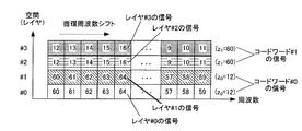


Classifications
-
- H—ELECTRICITY
- H04—ELECTRIC COMMUNICATION TECHNIQUE
- H04L—TRANSMISSION OF DIGITAL INFORMATION, e.g. TELEGRAPHIC COMMUNICATION
- H04L27/00—Modulated-carrier systems
- H04L27/26—Systems using multi-frequency codes
- H04L27/2601—Multicarrier modulation systems
- H04L27/2602—Signal structure
-
- H—ELECTRICITY
- H04—ELECTRIC COMMUNICATION TECHNIQUE
- H04L—TRANSMISSION OF DIGITAL INFORMATION, e.g. TELEGRAPHIC COMMUNICATION
- H04L27/00—Modulated-carrier systems
- H04L27/26—Systems using multi-frequency codes
-
- G—PHYSICS
- G06—COMPUTING OR CALCULATING; COUNTING
- G06F—ELECTRIC DIGITAL DATA PROCESSING
- G06F17/00—Digital computing or data processing equipment or methods, specially adapted for specific functions
- G06F17/10—Complex mathematical operations
- G06F17/14—Fourier, Walsh or analogous domain transformations, e.g. Laplace, Hilbert, Karhunen-Loeve, transforms
- G06F17/141—Discrete Fourier transforms
-
- H—ELECTRICITY
- H04—ELECTRIC COMMUNICATION TECHNIQUE
- H04J—MULTIPLEX COMMUNICATION
- H04J1/00—Frequency-division multiplex systems
-
- H—ELECTRICITY
- H04—ELECTRIC COMMUNICATION TECHNIQUE
- H04J—MULTIPLEX COMMUNICATION
- H04J11/00—Orthogonal multiplex systems, e.g. using WALSH codes
-
- H—ELECTRICITY
- H04—ELECTRIC COMMUNICATION TECHNIQUE
- H04J—MULTIPLEX COMMUNICATION
- H04J4/00—Combined time-division and frequency-division multiplex systems
- H04J4/005—Transmultiplexing
-
- H—ELECTRICITY
- H04—ELECTRIC COMMUNICATION TECHNIQUE
- H04L—TRANSMISSION OF DIGITAL INFORMATION, e.g. TELEGRAPHIC COMMUNICATION
- H04L27/00—Modulated-carrier systems
- H04L27/26—Systems using multi-frequency codes
- H04L27/2601—Multicarrier modulation systems
- H04L27/2626—Arrangements specific to the transmitter only
- H04L27/2627—Modulators
- H04L27/2634—Inverse fast Fourier transform [IFFT] or inverse discrete Fourier transform [IDFT] modulators in combination with other circuits for modulation
- H04L27/2636—Inverse fast Fourier transform [IFFT] or inverse discrete Fourier transform [IDFT] modulators in combination with other circuits for modulation with FFT or DFT modulators, e.g. standard single-carrier frequency-division multiple access [SC-FDMA] transmitter or DFT spread orthogonal frequency division multiplexing [DFT-SOFDM]
-
- H—ELECTRICITY
- H04—ELECTRIC COMMUNICATION TECHNIQUE
- H04L—TRANSMISSION OF DIGITAL INFORMATION, e.g. TELEGRAPHIC COMMUNICATION
- H04L5/00—Arrangements affording multiple use of the transmission path
- H04L5/003—Arrangements for allocating sub-channels of the transmission path
- H04L5/0037—Inter-user or inter-terminal allocation
- H04L5/0041—Frequency-non-contiguous
-
- H—ELECTRICITY
- H04—ELECTRIC COMMUNICATION TECHNIQUE
- H04W—WIRELESS COMMUNICATION NETWORKS
- H04W72/00—Local resource management
- H04W72/04—Wireless resource allocation
- H04W72/044—Wireless resource allocation based on the type of the allocated resource
- H04W72/0453—Resources in frequency domain, e.g. a carrier in FDMA
-
- H—ELECTRICITY
- H04—ELECTRIC COMMUNICATION TECHNIQUE
- H04W—WIRELESS COMMUNICATION NETWORKS
- H04W88/00—Devices specially adapted for wireless communication networks, e.g. terminals, base stations or access point devices
- H04W88/08—Access point devices
-
- Y—GENERAL TAGGING OF NEW TECHNOLOGICAL DEVELOPMENTS; GENERAL TAGGING OF CROSS-SECTIONAL TECHNOLOGIES SPANNING OVER SEVERAL SECTIONS OF THE IPC; TECHNICAL SUBJECTS COVERED BY FORMER USPC CROSS-REFERENCE ART COLLECTIONS [XRACs] AND DIGESTS
- Y10—TECHNICAL SUBJECTS COVERED BY FORMER USPC
- Y10S—TECHNICAL SUBJECTS COVERED BY FORMER USPC CROSS-REFERENCE ART COLLECTIONS [XRACs] AND DIGESTS
- Y10S370/00—Multiplex communications
- Y10S370/916—Multiplexer/demultiplexer
Definitions
- the present invention relates to a wireless communication apparatus and a signal division method.
- 3rd Generation Generation Partnership Project Long Long Term Evolution studies on standardization of mobile communication standards are being actively conducted in order to realize high-speed transmission with low delay.
- OFDM Orthogonal-Frequency-Division-Multiplexing
- DFT Discrete
- SC-FDMA Single-Carrier Frequency Division Multiple Access
- a DFT matrix precoding matrix or DFT sequence
- N is the DFT size (number of DFT points).
- N N ⁇ 1 column vectors are orthogonal to each other with a DFT size of N.
- SC-FDMA using DFT precoding an SC-FDMA signal (spectrum) is formed by spreading and code-multiplexing a symbol sequence using this DFT matrix.
- LTE-Advanced Long Term Evolution-Advanced
- IMT International Mobile Telecommunication
- a radio communication base station apparatus hereinafter referred to as a base station
- a radio communication terminal apparatus hereinafter referred to as a terminal
- uplink frequency resource allocation is SC-FDMA. Restricted to assignments that map signals locally (localized) to successive frequency bands.
- the uplink shared frequency resource for example, PUSCH (Physical Uplink Shared CHannel)
- PUSCH Physical Uplink Shared CHannel
- -FDMA clustered SC-FDMA
- a terminal In the above-described conventional C-SC-FDMA, a terminal generates a C-SC-FDMA signal by dividing an SC-FDMA signal (spectrum) generated by DFT processing into a plurality of clusters. Then, the terminal maps the plurality of clusters to discontinuous frequency resources (subcarriers or resource blocks (Resource (Block: RB)).
- the base station performs frequency domain equalization (FDE) processing on the received C-SC-FDMA signal (a plurality of clusters) to combine the plurality of equalized clusters. Then, the base station performs an IDFT (Inverse Discrete Fourier Transform) process on the combined signals to obtain a time domain signal.
- FDE frequency domain equalization
- IDFT Inverse Discrete Fourier Transform
- frequency resources can be allocated among a plurality of terminals more flexibly than SC-FDMA by mapping a plurality of clusters to a plurality of discontinuous frequency resources.
- the utilization efficiency and the multiuser diversity effect can be improved.
- since the PAPR is smaller than that of OFDMA (Orthogonal Frequency Division Multiple Access), it is possible to expand the uplink coverage more than OFDMA.
- the base station determines the SC-FDMA signal (spectrum) of each terminal according to the availability of uplink frequency resources or the state of the propagation path between a plurality of terminals and the base station. Are allocated to a plurality of uplink frequency resources, and information indicating the allocation result is notified to the terminal.
- the terminal divides the SC-FDMA signal (spectrum), which is the output of the DFT processing, by an arbitrary bandwidth, and maps the plurality of clusters to the plurality of uplink frequency resources allocated by the base station. -Generate an SC-FDMA signal.
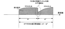
- the uplink broadband radio frequency band (broadband radio channel) has frequency selectivity, the frequency correlation between channels through which a plurality of clusters mapped to discontinuous different frequency bands respectively propagate becomes low. Therefore, even when the base station equalizes the C-SC-FDMA signal (multiple clusters) by FDE processing, the equivalent channel gain for each of the clusters (that is, the frequency channel gain after FDE weight multiplication) is greatly different. There can be. Therefore, the equivalent channel gain may change abruptly at the coupling point of a plurality of clusters (that is, the division point where the terminal divides the SC-FDMA signal). That is, a discontinuous point occurs in the fluctuation of the equivalent channel gain (that is, the envelope of the reception spectrum) at the coupling point of a plurality of clusters.
- the C-SC-FDMA signal is likely to be affected by inter-symbol interference (ISI) resulting from the loss of orthogonality of the DFT matrix.
- ISI inter-symbol interference
- high-level multi-level modulation such as 64QAM with a very short Euclidean distance between signal points
- it is more susceptible to ISI, so that the transmission characteristics are further deteriorated.
- the number of clusters the number of SC-FDMA signal divisions
- the number of discontinuities between clusters increases, so that the ISI due to the loss of orthogonality of the DFT matrix increases.
- the present invention has been made in view of the above points.
- an SC-FDMA signal is divided into a plurality of clusters and each of the plurality of clusters is mapped to a discontinuous frequency band, that is, C-SC-FDMA. It is an object of the present invention to provide a radio communication apparatus and a signal division method that can reduce ISI caused by the loss of orthogonality of the DFT matrix even when using the DFT matrix.
- the wireless communication apparatus includes a transform unit that performs DFT processing on a symbol sequence using a DFT matrix to generate a frequency domain signal, and any one of a plurality of column vectors that constitute the DFT matrix.
- a dividing unit that divides the signal by a partial orthogonal bandwidth corresponding to orthogonal vector lengths to generate a plurality of clusters; a mapping unit that maps the plurality of clusters to discontinuous frequency bands; The structure which comprises is taken.
- the signal is divided by width to generate a plurality of clusters.
- the orthogonality of the DFT matrix ISI resulting from the collapse of the can be reduced.
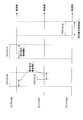
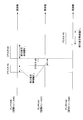
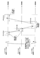
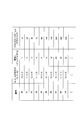
- the block block diagram of the terminal which concerns on Embodiment 1 of this invention The figure which shows the DFT process which concerns on Embodiment 1 of this invention.
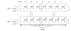
- the figure which shows the partial orthogonal relationship which concerns on Embodiment 1 of this invention (when
- 1)
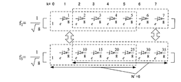
- the figure which shows the partial orthogonal relationship which concerns on Embodiment 1 of this invention (in the case of
- 2)
- 3)
- segmentation process and mapping process which concern on Embodiment 1 of this invention The figure which shows the signal after FDE which concerns on Embodiment 1 of this invention
- the figure which shows the shift process which concerns on Embodiment 5 of this invention (when z 3)
- segmentation process and mapping process which concern on Embodiment 5 of this invention The block block diagram of the terminal which concerns on Embodiment 5 of this invention.
- the block block diagram of the terminal which concerns on Embodiment 6 of this invention The figure which shows the DFT output which concerns on Embodiment 6 of this invention.
- the figure which shows the shift process which concerns on Embodiment 6 of this invention The figure which shows the division
- the figure which shows the DFT output which concerns on Embodiment 6 of this invention The figure which shows the shift process which concerns on Embodiment 6 of this invention.
- segmentation process and mapping process which concern on Embodiment 6 of this invention The block block diagram of the terminal which concerns on Embodiment 7 of this invention.
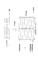
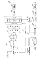
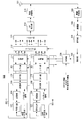
- FIG. 1 shows the configuration of terminal 100 according to the present embodiment.
- radio receiving section 102 receives a control signal transmitted from a base station (not shown) via antenna 101, and performs reception processing such as down-conversion and A / D conversion on the control signal.
- the control signal subjected to the reception process is output to the demodulation unit 103.
- This control signal includes frequency resource information indicating uplink frequency resources allocated to each terminal and MCS information indicating MCS (Modulation & channel? Coding? Scheme) set for each terminal.
- Demodulation section 103 demodulates the control signal and outputs the demodulated control signal to decoding section 104.
- the decoding unit 104 decodes the control signal and outputs the decoded control signal to the extraction unit 105.
- the extraction unit 105 extracts the frequency resource information addressed to the terminal included in the control signal input from the decoding unit 104, and outputs the extracted frequency resource information to the control unit 106.
- the control unit 106 receives the category information of the terminal including the DFT size (number of DFT points) of the DFT matrix used in the DFT unit 110 and partial orthogonal condition information indicating the partial orthogonal condition of the C-SC-FDMA signal described later.
- the frequency resource information notified from the base station is input from the extraction unit 105.
- the control unit 106 determines that the dividing unit 111 is an SC-FDMA signal (that is, The number of clusters generated by dividing the output of the DFT unit 110) and the cluster size indicating the bandwidth of each cluster are calculated.
- SC-FDMA signal spectrum
- the one with the lower spectrum frequency the one with the smaller output number of the DFT unit 110
- the one with the higher spectrum frequency the output of the DFT unit 110.
- control unit 106 calculates a frequency resource to which the C-SC-FDMA signal (multiple clusters) of its own terminal is mapped. For example, the control unit 106 has a cluster with a low frequency (a cluster with a small output number of the DFT unit 110) or a cluster with a high frequency (a large output number of the DFT unit 110) among a plurality of clusters generated by division. In order from the cluster, frequency resources to which the cluster is mapped are calculated.
- control unit 106 inputs the cluster information including the calculated number of clusters and the cluster size to the dividing unit 111, and mapping information indicating the frequency resource to which the C-SC-FDMA signal (multiple clusters) of its own terminal is mapped Is output to the mapping unit 112.
- the encoding unit 107 encodes the transmission bit sequence and outputs the encoded transmission bit sequence to the modulation unit 108.
- the modulation unit 108 modulates the transmission bit sequence input from the encoding unit 107 to generate a symbol sequence, and outputs the generated symbol sequence to the multiplexing unit 109.
- the multiplexing unit 109 multiplexes the pilot signal and the symbol sequence input from the modulation unit 108. Then, multiplexing section 109 outputs a symbol sequence in which pilot signals are multiplexed to DFT section 110.
- a CAZAC (ConstantACAmplitude Zero Auto Correlation) sequence may be used as the pilot signal.
- the pilot signal and the symbol sequence are multiplexed before the DFT processing is performed. However, the pilot signal and the symbol sequence may be multiplexed after the DFT processing is performed.
- the DFT section 110 generates a frequency domain signal (SC-FDMA signal) by performing DFT processing on the time domain symbol sequence input from the multiplexing section 109 using the DFT matrix. Then, the DFT unit 110 outputs the generated SC-FDMA signal (spectrum) to the dividing unit 111.
- SC-FDMA signal frequency domain signal
- the dividing unit 111 divides the SC-FDMA signal (spectrum) input from the DFT unit 110 into a plurality of clusters according to the number of clusters and the cluster size indicated in the cluster information input from the control unit 106. Specifically, dividing section 111 has a bandwidth (partial orthogonal bandwidth) corresponding to a length (vector length) in which one of the plurality of column vectors constituting the DFT matrix used in DFT section 110 is partially orthogonal. To divide the SC-FDMA signal (spectrum) to generate a plurality of clusters. Then, division section 111 outputs the generated C-SC-FDMA signal composed of a plurality of clusters to mapping section 112. The details of the method of dividing the SC-FDMA signal (spectrum) in the dividing unit 111 will be described later.
- the mapping unit 112 maps the C-SC-FDMA signal (a plurality of clusters) input from the dividing unit 111 to frequency resources (subcarriers or RBs) based on the mapping information input from the control unit 106. For example, the mapping unit 112 maps a plurality of clusters constituting the C-SC-FDMA signal to a plurality of discontinuous frequency bands. Then, mapping section 112 outputs the C-SC-FDMA signal mapped to the frequency resource to IFFT section 113.
- the IFFT unit 113 performs IFFT on a plurality of frequency bands to which the C-SC-FDMA signal input from the mapping unit 112 is mapped, and generates a time-domain C-SC-FDMA signal.
- IFFT section 113 inserts 0 in a frequency band other than a plurality of frequency bands to which the C-SC-FDMA signal (a plurality of clusters) is mapped. Then, IFFT section 113 outputs the C-SC-FDMA signal in the time domain to CP (Cyclic Prefix) insertion section 114.
- the CP insertion unit 114 adds the same signal as the tail part of the C-SC-FDMA signal input from the IFFT unit 113 as a CP to the head of the C-SC-FDMA signal.
- the wireless transmission unit 115 performs transmission processing such as D / A conversion, amplification and up-conversion on the C-SC-FDMA signal, and transmits the signal subjected to the transmission processing to the base station via the antenna 101.
- the base station performs FDE processing for multiplying FDE weights on the C-SC-FDMA signals (multiple clusters) transmitted from each terminal, and performs CDE-multiple C-SC-FDMA signals (multiple clusters) after FDE processing. Cluster) in the frequency domain. Then, the base station obtains a time-domain signal by performing IDFT processing on the combined C-SC-FDMA signal.
- the base station uses a pilot signal transmitted from each terminal to measure SINR (Signal-to-Interference plus Noise power Ratio) for each frequency band (for example, subcarrier) between each terminal and the base station. As a result, channel quality information (for example, CQI: Channel QualitydicIndicator) of each terminal is generated.
- CQI Channel QualitydicIndicator
- the base station schedules allocation of uplink frequency resources (for example, PUSCH) of each terminal using CQI and QoS (Quality of Service) of the plurality of terminals. Then, the base station notifies each terminal of frequency resource information indicating an uplink frequency resource allocation result (ie, scheduling result) of each terminal.
- PF Proportional Fairness
- the base station controls the number of clusters and the cluster size using the DFT size and the partial orthogonality condition, and the C-SC-FDMA signal is based on the number of clusters and the cluster size.
- Join multiple clusters.
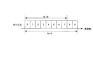
- the SC-FDMA signal that is the output of the DFT section 110 is obtained by orthogonally spreading each symbol of the symbol sequence to a frequency band corresponding to the DFT size (column vector length) of the DFT matrix, Is code-multiplexed.
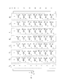
- DFT section 110 performs frequency spreading on symbols # 0 to # 7 with column vectors f 0 to f 7 of the DFT matrix, respectively.
- DFT section 110 code-multiplexes frequency-spread symbols # 0 to # 7.
- an SC-FDMA signal having an orthogonal bandwidth corresponding to the DFT size N is obtained.
- the column vector f i of the DFT matrix F is orthogonal to all other column vectors with the DFT size N, and in addition, the vector length N ′ (where N ′ is smaller than the DFT size (column vector length) N).
- ⁇ N) is also partially orthogonal to some other column vectors.
- any two column vectors f i and f i ′ (where i ′ ⁇ i) different from each other are partially orthogonal, and the DFT between the DFT size (column vector length) N of the matrix F, there is a relationship (partial orthogonal condition) of the following equation (1).
- I is a non-zero integer that satisfies
- the bandwidth (that is, the orthogonal bandwidth of the DFT matrix) B corresponding to the DFT size N of the DFT matrix is represented by N * B sub .
- B sub indicates an orthogonal frequency interval (subcarrier interval).
- the partial orthogonal bandwidth B ′ corresponding to the vector length N ′ (where N ′ ⁇ N) where the column vector f i and the column vector f i ′ are partially orthogonal is represented by N ′ * B sub .
- the orthogonal bandwidth of the DFT matrix that is, the relationship (partial orthogonal condition) between the total bandwidth (orthogonal bandwidth) B and the partial orthogonal bandwidth B ′ used for SC-FDMA signal transmission is as follows. It can be represented by Formula (2).
- each cluster is mapped to a discontinuous frequency band. Therefore, a sudden change in the equivalent channel gain (discontinuous point) occurs at the cluster connection point. Is likely to occur.
- the fluctuation of the equivalent channel gain becomes slow by performing the FDE processing. That is, even if a sudden fluctuation (discontinuity point) of the equivalent channel gain occurs (when the orthogonality of the DFT matrix is lost due to the orthogonal bandwidth of the DFT matrix), the ISI is reduced by maintaining the orthogonality within the cluster. It becomes possible to do.
- B ′ the partial orthogonal bandwidth
- each cluster size has a partial orthogonal bandwidth B ′ satisfying Equation (2) (or Equation (1)), and an orthogonal bandwidth B and a partial orthogonal bandwidth B ′.
- the DFT size N is 8.
- mapping section 112 maps cluster # 0 and cluster # 1 to two discontinuous frequency bands.
- the variation of the equivalent channel gain is discontinuous at the connection point between cluster # 0 and cluster # 1.
- the variation of the equivalent channel gain is slow within each cluster. Therefore, in cluster # 0, ISI between multiple symbols corresponding to column vectors f i and f i ′ satisfying equation (2) or equation (1) (that is, between partially orthogonal symbols) is reduced.
- the equivalent channel gain at the coupling point (dividing point of the SC-FDMA signal) between the cluster # 0 and the cluster # 1 is rapidly changed. The resulting ISI can be reduced.
- the present division method although the fluctuation of the equivalent channel gain becomes discontinuous at the coupling point of a plurality of clusters, the collapse of the orthogonality between multiple symbols is reduced in the cluster of the partial orthogonal bandwidth. be able to. Therefore, according to this division method, even when the SC-FDMA signal is divided into a plurality of clusters, ISI due to abrupt fluctuation of the equivalent channel gain can be reduced.
- the dividing unit 111 has (
- An SC-FDMA signal is divided by a partial orthogonal bandwidth B ′ corresponding to a certain vector length N ′.
- the DFT size N is 12 and the number of clusters is 2.
- the dividing unit 111 is (
- ) ⁇ 1 2, 3, 4, which is the reciprocal of (
- ) shown in Expression (1). 6 is selected. That is, the dividing unit 111 selects any one of the vector lengths N ′ 6, 4, 3, and 2 from Expression (1). That is, in the expression (1), the column vector f i and the column vector f i ′ satisfying (
- ) 1/2, 1/3, 1/4, and 1/6, respectively.
- ) ⁇ 1 2) ),
- the same effects as those of the division method 1 are obtained, and the DFT processing for outputting the SC-FDMA signal using the integer DFT size N and the SC-F that is the output of the DFT processing. It is possible to improve the affinity with the division processing for dividing the FDMA signal into a plurality of clusters.
- division section 111 divides the SC-FDMA signal with partial orthogonal bandwidth B ′ corresponding to vector length N ′ that is a multiple of prime numbers.
- division section 111 a multiple a 0 x 0 of prime number x 0 the vector length N '(where coefficient a 0 is an integer of 1 or more) and.
- the DFT size N is 12 and the number of clusters is 2.
- the vector length 3 matches one period of the column vector f 4 and two periods of the column vector f 8
- the vector length 6 is equal to the column vector f 4. of matches and four periods of two cycles and column vector f 8
- vector length 9 matches with 6 cycles of three cycles and column vector f 8 column vector f 4.
- the division unit 111 divides the SC-FDMA signal by the partial orthogonal bandwidth B ′ corresponding to the vector length N ′ that is a multiple a 0 x 0 of the prime number x 0 , thereby providing a prime number.
- x multiples of 0 (x 0, 2x 0, ..., a 0 x 0) period is capable of generating a cluster including increasing the number of multiple symbols hierarchically orthogonal. That is, it is possible to ensure a large number of multiple symbols (column vectors) that are partially orthogonal with the cluster size of the clusters generated by dividing the SC-FDMA signal.
- the control information related to the SC-FDMA signal (spectrum) division the information that needs to be notified from the base station to the terminal 100 only needs to be the coefficient a 0 , so the amount of information required for the control information notification Can be reduced.
- the division unit 111 may divide the SC-FDMA signal by the partial orthogonal bandwidth B ′ corresponding to the vector length N ′ that is a multiple of the product of two or more prime numbers.
- the dividing unit 111 sets the vector length N ′ to a multiple of a product (for example, x 0 * x 1 ) of at least two prime numbers (two or more prime numbers) among the prime numbers x 0 , x 1 , x 2 ,. (For example, b 0 (x 0 * x 1 )) (where b 0 is an integer of 1 or more).
- the division unit 111 divides the SC-FDMA signal with the partial orthogonal bandwidth B ′ corresponding to the vector length N ′ that is a power of a prime number.
- the dividing unit 111 sets the column vector length N ′ to a power x 0 a0 of a prime number x 0 (where a 0 is an integer of 1 or more).
- the DFT size N is set to 12
- the number of clusters is set to 2.
- the column vectors f 0 , f 3 , and f 6 have a cycle of vector lengths 2, 4, and 8, respectively.
- the division unit 111 divides the SC-FDMA signal by the partial orthogonal bandwidth B ′ corresponding to the vector length N ′ that is a power x 0 a0 of the prime number x 0 , thereby obtaining a prime number x.
- power of 0 (x 0, x 0 2 , ..., x 0 a0) can generate a cluster including more multiplexed symbols (column vectors) which hierarchically partially orthogonal in a cycle of. Therefore, similar to the division method 1-3, it is possible to reduce ISI caused by the loss of orthogonality between multiple symbols (column vectors) that are not partially orthogonal with the cluster size of a cluster generated by dividing an SC-FDMA signal. it can.
- the control information related to the division of the SC-FDMA signal (spectrum)
- the information that needs to be notified from the base station to the terminal 100 need only be the coefficient a 0 .
- the amount of information required for notification of control information can be reduced.
- the division unit 111 may divide the SC-FDMA signal by the partial orthogonal bandwidth B ′ corresponding to the vector length N ′ that is the power of the product of two or more prime numbers.
- the dividing unit 111 raises the vector length N ′ to the power of a product (for example, x 0 * x 1 ) of at least two prime numbers (two or more prime numbers) among the prime numbers x 0 , x 1 , x 2 ,. (e.g., (x 0 * x 1) b0) and (However, b 0 is an integer of 1 or more).
- a product for example, x 0 * x 1
- b0 is an integer of 1 or more.
- the dividing unit 111 sets the vector length N ′ to a product (for example, x 0 * x) of at least two prime numbers (two or more prime numbers) among the prime numbers x 0 , x 1 , x 2 ,. 1 ) to a power (for example, a multiple of (x 0 * x 1 ) b 0 ) (for example, p 0 (x 0 * x 1 ) b 0 )) (where p 0 is an integer of 1 or more).
- a product for example, x 0 * x
- a power for example, a multiple of (x 0 * x 1 ) b 0 ) (for example, p 0 (x 0 * x 1 ) b 0 )) (where p 0 is an integer of 1 or more).
- the dividing unit 111 sets the vector length N ′ to the powers x 0 c0 , x 1 c1 ,... (C 0 , c 1 ,...) Of prime numbers x 0 , x 1 ,.
- c 0, c 1, ... at least one of at least two (two or more) of product x 0 c0 * x 1 c1 * ... it may be of an integer of 1 or more) of the. Even in this case, an effect similar to that of the present dividing method can be obtained.
- FFT Fast Fourier Transform
- the SC-FDMA signal dividing method 1-1 to 1-4 in the dividing unit 111 has been described above.
- the SC-FDMA signal is divided into a plurality of clusters and each of the plurality of clusters is mapped to a discontinuous frequency band, the SC-FDMA signal is divided into partial orthogonal bandwidths.
- the SC-FDMA signal is divided into partial orthogonal bandwidths.
- the present embodiment even when high-level multilevel modulation such as 64QAM such as a very short Euclidean distance between signal points is used by reducing ISI caused by the loss of orthogonality of the DFT matrix.
- the transmission characteristics can be improved without reducing the data transmission efficiency.
- the terminal divides the SC-FDMA signal into a plurality of clusters so that the bandwidth of one cluster (here, cluster # 0) becomes a partial orthogonal bandwidth.
- the terminal uses, for example, any one of the division methods 1-1 to 1-4, and uses a plurality of SC-FDMA signals so that the bandwidth of all of the plurality of clusters becomes a partial orthogonal bandwidth. It may be divided into clusters. As a result, in all the clusters, it is possible to increase multiple symbols that are in a partially orthogonal relationship, so that ISI can be reduced for each cluster.
- the terminal may perform frequency interleaving for each frequency band (or cluster) having a partial orthogonal bandwidth.
- the interleaving unit (not shown) performs frequency interleaving in units of partial orthogonal bandwidths. . That is, the interleaving unit, 'first half of the cluster # 0 having the partial orthogonal bandwidth B 0' portion orthogonal bandwidth B 0 in the cluster # 1 of the second half section and portions orthogonal bandwidth B 1 'of cluster # 0 having Frequency interleaving is performed.
- the interleaving unit 'first half of the cluster # 0 having the partial orthogonal bandwidth B 0' portion orthogonal bandwidth B 0 in the cluster # 1 of the second half section and portions orthogonal bandwidth B 1 'of cluster # 0 having Frequency interleaving is performed.
- the base station notifies only frequency resource information to terminal 100 every time it communicates with terminal 100, and category information and partial orthogonality condition information (formula (1)) that terminal 100 has previously notified.
- category information and partial orthogonality condition information (formula (1)) that terminal 100 has previously notified.
- the cluster information (the number of clusters and the cluster size) is calculated based on the equation (2)) has been described.
- the base station notifies all of the frequency resource information and the cluster information (the number of clusters and the cluster size) to the terminal 100 every time it communicates with the terminal 100, and the terminal 100
- the SC-FDMA signal may be divided based on resource information and cluster information.
- the base station may notify the terminal 100 of frequency resource information indicating a frequency band assigned in consideration of the number of clusters and the cluster size.
- the base station (base station scheduler) includes, for example, the terminal 100 that exhibits the maximum SINR in a certain frequency band (subcarrier) by performing scheduling, and includes the expression ( 2) An allocation process for allocating a frequency band having a partial orthogonal bandwidth B ′ satisfying (or Expression (1)) is performed. That is, the base station assigns the frequency band of the partial orthogonal bandwidth B ′ calculated by Expression (2) (or Expression (1)) to a plurality of clusters constituting the C-SC-FDMA signal of terminal 100.
- the base station performs frequency resource allocation of C-SC-FDMA signals composed of a plurality of clusters having partial orthogonal bandwidths by repeatedly performing the above allocation processing in different frequency bands. Then, the base station notifies terminal 100 of frequency resource information indicating a frequency resource allocation result of the C-SC-FDMA signal of terminal 100. The base station performs the frequency resource allocation process for terminals other than the terminal 100. Thereby, the base station can schedule the allocation of frequency resources to all terminals located in the cell of the own station. Also, terminal 100 may map the C-SC-FDMA signal according to the frequency band indicated in the frequency resource information notified from the base station. Thereby, in terminal 100, SC-FDMA is divided into a plurality of clusters, and the plurality of clusters are mapped to the frequency bands of the partial orthogonal bandwidth, so that the same effect as in the present embodiment can be obtained.
- MIMO Multi-Input Multi-Output
- both base stations and terminals are provided with a plurality of antennas, a plurality of propagation paths (streams) are prepared in a space between wireless transmission and reception, and each stream is spatially multiplexed to increase throughput. be able to.
- FIG. 9 shows the configuration of terminal 200 according to the present embodiment.
- Terminal 200 includes two antennas (antennas 101-1 and 101-2) that transmit C-SC-FDMA signals (multiple clusters) using two streams (stream # 1 and stream # 2). .
- terminal 200 uses C-SC-FDMA processing units 201-1 and 201-2 including encoding unit 107, modulation unit 108, multiplexing unit 109, DFT unit 110, and division unit 111 as antennas 101-1 and 101-. It prepares corresponding to 2.
- terminal 200 includes transmission processing sections 203-1 and 203-2 each including mapping section 112, IFFT section 113, CP insertion section 114, and wireless transmission section 115, corresponding to antennas 101-1 and 101-2.
- the C-SC-FDMA processing units 201-1 and 201-2 perform the same processing as that of the encoding unit 107 to the division unit 111 of the first embodiment on the transmission bit sequences input to them, respectively.
- C-SC-FDMA signal (multiple clusters) is generated.
- C-SC-FDMA processing units 201-1 and 201-2 output the generated C-SC-FDMA signals to precoding unit 202, respectively.
- the precoding unit 202 is input with different spatial precoding matrices (Precoding (Matrix: PM) from the control unit 106 for each identical frequency band having a partial orthogonal bandwidth or for each identical cluster of partial orthogonal bandwidths. That is, the precoding unit 202 uses the same spatial precoding matrix for each identical frequency band having a partial orthogonal bandwidth or for each identical cluster of partial orthogonal bandwidths.
- precoding information indicating a spatial precoding matrix is notified from terminal to terminal 200.
- the precoding information may indicate a number indicating each spatial precoding matrix, and the control unit 106 may calculate each spatial precoding matrix based on the number indicated in the precoding information.
- the precoding unit 202 multiplies the C-SC-FDMA signals respectively input from the C-SC-FDMA processing units 201-1 and 201-2 by a spatial precoding matrix.
- the precoding unit 202 is identical to a C-SC-FDMA signal mapped to a frequency band having the same partial orthogonal bandwidth or a cluster having the same partial orthogonal bandwidth in each of a plurality of streams. Multiply each of the spatial precoding matrices.
- Precoding section 202 then outputs the precoded C-SC-FDMA signal to transmission processing sections 203-1 and 203-2 corresponding to each stream.
- Transmission processing sections 203-1 and 203-2 perform the same processing as mapping section 112 to radio transmission section 115 of Embodiment 1 on the pre-coded C-SC-FDMA signal input to each. Then, the C-SC-FDMA signal after transmission processing is transmitted to the base station via antennas 101-1 and 101-2, respectively.
- each of the division units 111 (FIG. 9) of the C-SC-FDMA processing units 201-1 and 201-2 has a bandwidth that is twice the partial orthogonal bandwidth B 0 ′.
- the cluster # 0 is divided into the cluster # 1 having the partial orthogonal bandwidth B 1 ′.
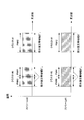
- precoding section 202 multiplies cluster # 0 and cluster # 1 transmitted using stream # 1 and stream # 2 by the same spatial precoding matrix for each partial orthogonal bandwidth. Specifically, as shown in FIG. 10A, the precoding unit 202 uses the same spatial precoding in both stream # 1 and stream # 2 in one partial orthogonal bandwidth B 0 ′ of cluster # 0. Using the matrix PM # 0 and the other partial orthogonal bandwidth B 0 ′, the same spatial precoding matrix PM # 1 is used for both the stream # 1 and the stream # 2. Also, precoding section 202 uses the same spatial precoding matrix PM # 2 in both stream # 1 and stream # 2 in cluster # 1 having partial orthogonal bandwidth B 1 ′.
- each of the division units 111 (FIG. 9) of the C-SC-FDMA processing units 201-1 and 201-2 transmits the SC-FDMA signal to the cluster # 0 having the partial orthogonal bandwidth B 0 ′.
- cluster # 1 having partial orthogonal bandwidth B 1 ′.
- Precoding section 202 multiplies cluster # 0 and cluster # 1 transmitted using stream # 1 and stream # 2 by the same spatial precoding matrix for each cluster. Specifically, as shown in FIG. 10B, in the cluster # 0 having the partial orthogonal bandwidth B 0 ′, the precoding unit 202 uses the same spatial precoding matrix PM # in both the stream # 1 and the stream # 2. 0 is used. Also, precoding section 202 uses the same spatial precoding matrix PM # 2 in both stream # 1 and stream # 2 in cluster # 1 having partial orthogonal bandwidth B 1 ′.
- the multiple symbols in each cluster By maintaining orthogonality between (column vectors), ISI can be reduced, and in the spatial domain, orthogonal orthogonal precoding matrices (for example, unitary matrices) can be used to be orthogonal to each other. That is, ISI can be further reduced between cluster # 0 of stream # 1 and cluster # 1 of stream # 2 (that is, between clusters transmitted in different frequency bands and different streams). The same applies to the cluster # 1 of the stream # 1 and the cluster # 0 of the stream # 2.
- the same spatial precoding matrix is used for the same partial orthogonal bandwidth (or for each cluster) in different streams, thereby reducing ISI between different streams and between different frequency bands. can do.
- the present embodiment as in the first embodiment, by dividing the SC-FDMA signal by the partial orthogonal bandwidth, it is possible to reduce ISI in the frequency domain, and By using a spatial precoding matrix for each orthogonal bandwidth, ISI in the spatial domain can be reduced.
- the present embodiment provides single user (SU) -MIMO transmission (that is, MIMO transmission between a plurality of antennas of one base station and a plurality of antennas of one terminal) and multi-users (Multi User: MU) -MIMO transmission (that is, MIMO transmission between a plurality of antennas of one base station and a plurality of antennas of a plurality of terminals).
- SU single user
- MU multi-users
- the terminal may switch the transmission antenna for each frequency band (or cluster) having a partially orthogonal bandwidth. For example, as shown in FIG. 11, when the number of transmission antennas is 3 (antennas # 0 to # 2) and the number of clusters is 3 (clusters # 0 to # 2), it has a partial orthogonal bandwidth B 0 ′.
- FSTD Frequency Switched Transmit Diversity
- the first half of cluster # 0 is transmitted from antenna # 0
- the second half of cluster # 0 having partial orthogonal bandwidth B 0 ′ is transmitted from antenna # 1
- cluster # 1 having partial orthogonal bandwidth B 1 ′ is
- Cluster # 2 transmitted from antenna # 0 and having partial orthogonal bandwidth B 2 ′ may be transmitted from antenna # 2.
- FSTD by switching the transmission antennas in units of frequency bands (or clusters) having partial orthogonal bandwidths, different fading fluctuations between frequency bands (B 0 ′ to B 2 ′) having partial orthogonal bandwidths. Can receive. Therefore, a spatial diversity effect can be obtained while maintaining orthogonality within the frequency band of the partial orthogonal bandwidth.
- a cluster having a partial orthogonal bandwidth mapped to each antenna is mapped to a discontinuous frequency band, and at all antenna frequencies. Even when viewed, a plurality of clusters are mapped to discontinuous frequency bands. Specifically, in FIG. 11, an empty frequency band exists between antennas between cluster # 0 of antenna # 1 and cluster # 1 of antenna # 0. Similarly, an empty frequency band exists between antennas between cluster # 1 of antenna # 0 and cluster # 2 of antenna # 2. Further, in FIG. 11, no cluster is mapped to the vacant frequency band between antennas, and even when viewed in the frequency domain of all antennas, a plurality of clusters are mapped to discontinuous frequency bands. Yes.
- the cluster having the partial orthogonal bandwidth mapped to each antenna is a non-continuous frequency as in the second embodiment. Maps to bandwidth.
- a cluster having a partial orthogonal bandwidth mapped to each antenna has a partial orthogonal bandwidth in a continuous frequency band when viewed in the frequency domain of all antennas. A plurality of clusters having are mapped. That is, in FIG.
- the reception device (base station) side can perform reception processing in the same manner as when SC-FDMA signals are transmitted in a continuous frequency band from the transmission device (terminal) side.
- the receiving device (base station) can be used within the frequency band of the partial orthogonal bandwidth without being aware of the discontinuous mapping process between the antennas of the transmitting device (between spatial resources).
- the spatial diversity effect can be obtained while maintaining the orthogonality.
- FIG. 13 illustrates a plurality of clusters (clusters #A, #B, #C, and so on) so that the terminal rotates in order from the low frequency to the high frequency in the same direction of the antenna axis (or antenna direction, spatial resource region).
- #D is mapped to antennas # 0 to # 2 (spatial resources # 0 to # 2). Specifically, as shown in FIG.
- the terminal maps cluster #A to antenna # 0 (spatial resource # 0), maps cluster #B to antenna # 1 (spatial resource # 1), and #C is mapped to antenna # 2 (spatial resource # 2), and cluster #D is mapped to antenna # 0 (spatial resource # 0). That is, in FIG. 13, the terminal increases in the same direction (that is, as the frequency increases) in the antenna axis (or antenna direction, spatial resource region) in the order of antennas # 0, # 1, # 2, # 0,. Clusters #A, #B, #C, and #D are mapped so that the antenna numbers (spatial resource numbers) rotate in a rotational direction). Also, as shown in FIG. 13, the four clusters #A, #B, #C, and #D are mapped to continuous frequency bands when viewed in the frequency domain of all antennas, as in FIG.
- the frequency domain of antennas (spatial resources) for mapping a plurality of clusters is set cyclically, so that a plurality of antennas are used as frequency resource allocation information when mapping a plurality of clusters to the frequency domain of a plurality of antennas.
- One frequency resource allocation information (continuous frequency resource or non-continuous frequency resource) may be notified. Therefore, the same effect as this embodiment can be obtained while reducing the amount of information required for frequency resource allocation for each antenna.
- information about the rotation direction for example, the rotation direction in which the antenna number (spatial resource number, layer number) cyclically increases (decreases) as the frequency increases (decreases) in the antenna axis (spatial resource region).
- the rotation direction of the antenna axis (spatial resource region) in the frequency domain may be a rotational direction in which the antenna number (spatial resource number, layer number) decreases cyclically as the frequency increases.
- the rotation direction of the antenna axis may be switched for each frequency band (subband unit composed of a plurality of subcarriers, resource block unit or resource block group unit, etc.).
- the rotation direction of the antenna axis (spatial resource region) may be switched every certain time unit (symbol unit, slot unit, subframe unit, number of retransmissions, etc.).
- the rotation direction of the antenna axis (spatial resource region) may be switched for each time-frequency unit composed of two-dimensional resources in the time domain-frequency domain.
- the frequency band allocated to the terminal is divided into two, and as the frequency increases in one frequency band, the antenna number of the antenna to which each cluster is mapped rotates in a rotational direction, and in the other frequency band
- a plurality of clusters having partial orthogonal bandwidths may be mapped to a plurality of antennas in the rotation direction in which the antenna number of the antenna to which each cluster is mapped decreases cyclically as the frequency increases.
- each cluster increases as the frequency increases in the first slot.
- the antenna number of the antenna to which the cluster is mapped In the rotation direction in which the antenna number of the antenna to which the cluster is mapped increases cyclically, and in the second slot, as the frequency increases, the antenna number of the antenna to which each cluster is mapped is partially orthogonal to the rotation direction in which the antenna number decreases cyclically. Multiple clusters having bandwidth may be mapped to multiple antennas. Thereby, since the randomness of the channel in the frequency domain (or time domain) can be increased while maintaining the partial orthogonal relationship in each cluster, the diversity effect can be further improved.
- the antenna number of the antenna to which each cluster is mapped is rotated in the same direction of the antenna axis (or antenna direction, spatial resource region), so that a plurality of clusters are
- mapping to spatial resource
- the antenna number of the antenna to which each cluster is mapped is rotated in the same direction of the antenna axis (or antenna direction, spatial resource region), so that a plurality of clusters are (Spatial resource) may be mapped.
- FIG. 13 shows an example in which the terminal maps four clusters #A to #D to continuous frequency bands over a plurality of antennas while rotating between different antennas (antennas # 0 to # 2).
- the terminal may map a plurality of clusters to discontinuous frequency bands over the plurality of antennas in the same manner as in FIG. 11 while rotating between different antennas. That is, in FIG. 13, between cluster #A of antenna # 0 and cluster #B of antenna # 1, between cluster #B of antenna # 1 and cluster #C of antenna # 2, and cluster # of antenna # 2.
- An empty frequency band (a frequency band to which nothing is assigned) may exist between any clusters between C and cluster #D of antenna # 0.
- dividing section 111 uses SC- with a partial orthogonal bandwidth B ′ corresponding to vector length N ′ shown in (1) to (5) below.
- the case where the FDMA signal is divided has been described.
- Power of prime number x 0 : N ′ x 0 a0 (where a 0 is an integer of 1 or more)
- a finite value indicating an integer.
- the value of c i to be set is set to a value equal to or less than the exponent of the power whose base is larger.
- the control unit 106 if the power of the bottom (prime) have the relationship of x i ⁇ x i '(i ⁇ i'), the exponent c i corresponding to the bottom x i of the power c i ⁇ c i Set so that ' (i ⁇ i'). Therefore, when the base of the power is x 0 ⁇ x 1 ⁇ x 2 ⁇ ... ⁇ X M ⁇ 1 , the control unit 106 sets an index corresponding to the base of the power c 0 ⁇ c 1 ⁇ c 2 ⁇ ... ⁇ c Set so that M-1 is satisfied.
- division section 111 a plurality of power that constitutes the power of product indicating vector length N '(x 0 c0 * x 1 c1 * ... * x M-1 cM-1) (x 0 c0, x 1 c1, ..., x M-1 cM-1 ), and the exponent value c i of the power x i ci (i is one of 0 to (M-1)) is the base x i of the power x i ci
- Other powers with smaller bases x i ′ ci ′ that is, powers that should be x i ′ ⁇ x i , where i ′ ⁇ i
- column vectors having periods of 1, 2, 3, 4, 5, 6, 10, 12, 15, 20, 30, 60 are partially orthogonal to each other. Therefore, the number of partially orthogonal column vectors in the cluster is 12.
- the number of partially orthogonal column vectors in the cluster can be secured more. That is, in general, the larger the cluster size (here, vector length N ′) is, the more the number of column vectors of the DFT matrix partially orthogonal in the cluster can be increased, according to the present embodiment. In the cluster, the number of combinations of column vectors having a shorter period and partially orthogonal to each other can be increased.
- the cluster bandwidth is narrow (even when the cluster length is short), the number of partial orthogonal vectors in the cluster can be increased. Therefore, according to the present embodiment, compared with ⁇ partition method 1-4> of the first embodiment, it is possible to further reduce ISI caused by the loss of orthogonality of the DFT matrix in the cluster. .
- the cluster size of each cluster is equal to the condition ( Satisfies the power base (relationship between x 0 ⁇ x 1 ⁇ x 2 ⁇ ... ⁇ x M-1 ) and power exponent (c 0 ⁇ c 1 ⁇ c 2 ⁇ ... ⁇ c M-1 ) .
- the number of column vectors of the DFT matrix that are partially orthogonal in all clusters can be increased, so that the ISI caused by the collapse of the orthogonality of the DFT matrix can be further increased in the entire non-contiguously allocated band. Can be reduced.
- the terminal power of the base for example, x 0 ⁇ x 1 ⁇ ... ⁇ x M'-1 , and the power of exponent c 0 ⁇ c 1 ⁇ ... ⁇ c M'-1 and when made
- M ′ is a finite number indicating an integer of 2 or more.
- the terminal (dividing unit 111) divides the SC-FDMA signal with a partial orthogonal bandwidth of a multiple p 0 X (where p 0 is an integer equal to or greater than 1) of the minimum division unit X, thereby May be generated.
- the minimum division unit X (vector length N ′) for generating a cluster is set to x 0 c0 * x 1 c1 *... * X M′ ⁇ 1 cM′ ⁇ 1 ( ⁇ N)
- the multiplier p 0 is the same as the minimum division unit X May be represented by a product of powers using combinations of power bases (prime numbers) (x 0 , x 1 ,..., X M′ ⁇ 1 ).
- p 0 x 0 d0 * x 1 d1 *... * X M′ ⁇ 1 dM′ ⁇ 1 (d 0 , d 1 ,..., D M′ ⁇ 1 is an integer of 0 or more.
- a multiplier p 0 represented by at least one of d 0 , d 1 ,..., D M′ ⁇ 1 may be set. That is, the terminal (division unit) combines a plurality of power base combinations (x 0 c0 * x 1 c1 *... * X M′ ⁇ 1 cM′ ⁇ 1 ) that represent the minimum division unit X.
- the SC-FDMA signal is divided by the partial orthogonal bandwidth corresponding to the multiple p 0 X calculated by multiplying the minimum division unit X by the multiplier p 0 represented by... * X M′ ⁇ 1 dM′ ⁇ 1 ).
- the multipliers p 0 x 0 d0 * x 1 d1 *... * X M′ ⁇ 1 dM′ ⁇ 1 (d 0 , d 1 ,..., D M′ ⁇ 1 are integers of 0 or more.
- the terminal has a plurality of products constituting a product of powers that should represent the multiplier p 0
- the exponent d i corresponding to the power may be set to an equal value or a smaller value.
- the terminal when the power of the bottom of the multiplier p 0 (prime) have the relationship of x i ⁇ x i '(i ⁇ i'), the exponent d i corresponding to the bottom x i d i ⁇ d i Set so that ' (i ⁇ i'). Therefore, when the base of the power of the multiplier p 0 is in the relationship of x 0 ⁇ x 1 ⁇ x 2 ⁇ ... ⁇ x M′ ⁇ 1 , the terminal sets the exponent to d 0 ⁇ d 1 ⁇ d 2 ⁇ ... ⁇ d
- the multiplier p 0 may be set so as to satisfy the relationship of M′-1 .
- the terminal (dividing unit) has a power x which is a power among a plurality of powers constituting a product (x 0 d0 * x 1 d1 *... * X M′ ⁇ 1 dM′ ⁇ 1 ) that should represent the multiplier p 0.
- the value d i of the exponent of i di is, exponentiation x i 'di' (i.e. having a smaller bottom than the bottom x i of certain power x i di, 'power as a ⁇ x i.
- exponentiation x i has a certain power x i di larger bottom than the bottom x i of''di' '(that is, x i' power as a '> x i.
- the SC-FDMA signal is divided by the partial orthogonal bandwidth corresponding to the multiple p 0 X calculated by multiplying the minimum division unit X by the multiplier p 0 which is equal to or greater than the exponent value d i ′′ of i ′′ ⁇ i). To do.
- the multiplier (coefficient a 0 ) may be a power x 0 d0 of the prime number x 0 (where d 0 is an integer of 0 or more).
- the number of combinations of column vectors that are partially orthogonal to each other in a cycle of a power of x 0 can be increased.
- the ISI can be further reduced as compared with 1 ⁇ Division method 1-3>.
- an SC-FDMA signal is generated with a partial orthogonal bandwidth B ′ corresponding to a vector length N ′ that is a multiple of the product of two or more prime numbers.
- N ′ b 0 (x 0 * x 1 ) (where x 0 and x 1 are prime numbers, coefficient b 0 is an integer of 1 or more), that is, (x 0 * x 1 ) is the smallest
- Embodiment 5 In Embodiment 1 and Embodiment 4, as shown in FIG. 1, a dividing unit is connected to the DFT unit of the terminal, and the output signal (DFT output) of the DFT unit is directly divided by the dividing method described above, The case where a plurality of clusters are generated has been described. On the other hand, this Embodiment demonstrates the case where a shift part is provided between a DFT part and a division
- SC-FDMA signal spectrum-frequency shift
- FIG. 15 shows the configuration of the transmission apparatus (terminal) according to the present embodiment.
- the same components as those in Embodiment 1 (FIG. 1) are denoted by the same reference numerals, and the description thereof is omitted.
- a frequency domain signal (SC-FDMA signal) generated by performing DFT processing on the time domain symbol sequence is input from the DFT unit 110 to the shift unit 301, and a base station (or terminal) is received from the control unit 106. 300), the shift amount in the frequency domain (circulation frequency shift amount) set in step 300) is input.
- Shift section 301 then converts the SC-FDMA signal input from DFT section 110 into a DFT band (DFT size N) in the DFT processing in DFT section 110 according to the cyclic frequency shift amount input from control section 106. And frequency shift cyclically. That is, shift section 301 applies a cyclic frequency shift to the SC-FDMA signal within the DFT band.
- shift section 301 does not shift the cyclic frequency for the pilot symbol SC-FDMA signal (spectrum). May be. Then, shift section 301 outputs the SC-FDMA signal shifted in the cyclic frequency to division section 111.
- a detailed description of the cyclic frequency shift processing of the SC-FDMA signal (spectrum) in the shift unit 301 will be described later.
- Dividing section 111 uses the dividing method described in any of the above-described embodiments (for example, Embodiment 1 or Embodiment 4) to input SC-
- the FDMA signal is divided by a partially orthogonal length (vector length) N ′ to generate a plurality of clusters.
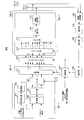
- FIG. 16 shows the configuration of the receiving apparatus (base station) according to the present embodiment.
- the base station 400 shown in FIG. 16 determines uplink frequency resource allocation, parameters related to spectrum division (cluster size, number of clusters, etc.) in each terminal, and cyclic frequency shift amount, and determines the determined information. Notify each terminal as notification information.
- base station 400 may notify the terminal of frequency resource allocation information that takes into account the effect of spectrum division based on parameters related to spectrum division and the amount of cyclic frequency shift.
- each terminal (terminal 300) divides the SC-FDMA signal (spectrum) that is cyclically frequency-shifted based on the spectrum division parameter included in the notification information notified from base station 400.
- the configuration excluding the reverse shift unit 408, that is, the configuration in which the output signal from the combining unit 407 is directly input to the IDFT unit 409 is described in the embodiment. 1 corresponds to the configuration of a receiving apparatus (base station) (not shown).
- 16 includes an antenna 401, a radio reception unit 402, a CP removal unit 403, an FFT unit 404, a demapping unit 405, an FDE unit 406, a combining unit 407, an inverse shift unit 408, and an IDFT unit. 409, a demodulation unit 410, a decoding unit 411, a measurement unit 412, a scheduler 413, a control unit 414, a generation unit 415, an encoding unit 416, a modulation unit 417, and a wireless transmission unit 418.
- radio receiving section 402 receives an uplink C-SC-FDMA signal transmitted from each terminal via antenna 401, down-converts the C-SC-FDMA signal, and performs A / D. Receive processing such as conversion is performed. Radio receiving section 402 then outputs the C-SC-FDMA signal subjected to the receiving process to CP removing section 403.
- CP removing section 403 removes the CP added to the head of the C-SC-FDMA signal input from radio receiving section 402 and converts the C-SC-FDMA signal after the CP removal into an FFT (Fast Fourier Transform) section.
- FFT Fast Fourier Transform
- the FFT unit 404 performs FFT on the CP-removed C-SC-FDMA signal input from the CP removing unit 403 and performs frequency domain C-SC-FDMA signal, that is, subcarrier component (orthogonal frequency). Component). Then, FFT section 404 outputs the subcarrier component after FFT to demapping section 405. Further, FFT section 404 outputs the subcarrier component to measurement section 412 when the subcarrier component after FFT is a pilot signal.
- the demapping unit 405 determines each subcarrier component of the frequency resource used by the target terminal from the subcarrier component input from the FFT unit 404.
- the C-SC-FDMA signal (data signal) assigned to (orthogonal frequency component) is demapped (extracted). Then, demapping section 405 outputs the demapped C-SC-FDMA signal to FDE section 406.
- the FDE unit 406 calculates an FDE weight based on the estimated value of the frequency channel gain between each terminal and the own station, which is estimated by an estimation unit (not shown), and uses the calculated FDE weight to demap the unit 405.
- the C-SC-FDMA signal input from is equalized in the frequency domain. Then, the FDE unit 406 outputs the post-FDE signal to the combining unit 407.
- the combining unit 407 receives the C-SC-FDMA signal input from the FDE unit 406 based on the cluster size and the number of clusters input from the control unit 414 (that is, the C-after-FDE composed of a plurality of clusters). SC-FDMA signal (spectrum)) is combined in the frequency domain. Then, combining section 407 outputs the combined C-SC-FDMA signal to inverse shift section 408.
- the inverse shift unit 408 follows the combined CDE after the FDE according to the cyclic frequency shift amount input from the control unit 414 (the cyclic frequency shift amount having the same magnitude as the cyclic frequency shift amount used by the shift unit 301 of the terminal 300).
- the SC-FDMA signal (spectrum) is cyclically shifted (that is, reverse circulation frequency shifted) in the opposite direction to the shift unit 301 of the terminal 300.
- the inverse shift unit 408 of the base station 400 performs ⁇ z (+ z) on the combined post-FDE signal.
- the cyclic frequency shift is performed.
- reverse shift section 408 outputs the C-SC-FDMA signal after the reverse circulation frequency shift to IDFT section 409.
- the IDFT unit 409 performs IDFT processing on the C-SC-FDMA signal (C-SC-FDMA signal (spectrum) combined after the FDE and shifted in reverse circulation frequency) input from the reverse shift unit 408 to obtain a time. Convert to domain signal. IDFT section 409 then outputs the time domain signal to demodulation section 410.
- Demodulation section 410 demodulates the time domain signal input from IDFT section 409 based on MCS information (modulation method) input from scheduler 413 and outputs the demodulated signal to decoding section 411.
- MCS information modulation method
- the decoding unit 411 decodes the signal input from the demodulation unit 410 based on the MCS information (coding rate) input from the scheduler 413, and outputs the decoded signal as a received bit string.
- the measurement unit 412 uses the pilot signal (the pilot signal transmitted from each terminal) included in the subcarrier component input from the FFT unit 404, and the channel quality of each terminal in the frequency domain, for example, each terminal By measuring SINR (Signal-to-Interference plus ⁇ Noise power Ratio) for each subcarrier, channel quality information (CQI: Channel Quality Information) of each terminal is generated. Then, the measurement unit 412 outputs the CQI of each terminal to the scheduler 413.
- SINR Signal-to-Interference plus ⁇ Noise power Ratio
- the scheduler 413 calculates the priority of the allocation of the uplink shared frequency resource (PUSCH: “Physical” Uplink “Shared” CHannel) to each terminal using information such as QoS (Quality “of” Service) of each terminal that is input. Then, the scheduler 413 uses the calculated priority and the CQI input from the measurement unit 412 to assign each subcarrier (or a frequency resource block RB (Resource) Block) configured from a plurality of subcarriers) to each subcarrier. Assign to a terminal.
- An algorithm used when assigning frequency resources includes PF (Proportional Fairness).
- the scheduler 413 outputs the frequency resource allocation information of each terminal indicating the frequency resource of each terminal allocated by the above method to the control unit 414 and the generation unit 415, and controls information other than the frequency resource allocation information (MCS information, etc.) ) To the demodulator 410, the decoder 411, and the generator 415.
- the control unit 414 receives frequency resource allocation information of each terminal input from the scheduler 413, terminal category information (information including DFT size), and partial orthogonal condition information (C-SC-FDMA partial orthogonal condition (formula ( The number of clusters and the cluster size of the terminal are calculated using the information 1) or (2)). Further, the control unit 414 calculates a frequency resource to which the C-SC-FDMA signal of each terminal is mapped based on the calculated number of clusters and cluster size. Then, control section 414 outputs the calculated number of clusters and cluster size to combining section 407, and outputs to the demapping section 405 frequency resource mapping information indicating the frequency resource to which the C-SC-FDMA signal of each terminal is mapped. To do. Also, the control unit 414 sets the cyclic frequency shift amount used in the reverse shift unit 408 and the shift unit 301 of the terminal 300, and outputs information related to the set cyclic frequency shift amount to the reverse shift unit 408 and the generation unit 415.
- the generation unit 415 receives frequency resource allocation information input from the scheduler 413, control information other than the frequency resource allocation information (MCS information and the like), and information on the cyclic frequency shift amount input from the control unit 414, for example, A control signal is generated by converting into a binary control bit sequence for notification to the terminal. Then, the generation unit 415 outputs the generated control signal to the encoding unit 416.
- MCS information frequency resource allocation information
- MCS information and the like information on the cyclic frequency shift amount input from the control unit 414
- the encoding unit 416 encodes the control signal input from the generation unit 415, and outputs the encoded control signal to the modulation unit 417.
- Modulation section 417 modulates the control signal input from encoding section 416 and outputs the modulated control signal to radio transmission section 418.
- the wireless transmission unit 418 performs transmission processing such as D / A conversion, amplification, and up-conversion on the control signal input from the modulation unit 417, and transmits the signal subjected to the transmission processing to each terminal via the antenna 401. Send.
- the DFT output (output signal of the DFT processing) is divided and generated even if it is cyclically shifted within the DFT band (DFT size N). If the cluster size is a length N ′ that satisfies Equation (1), a partial orthogonal relationship can be created between column vectors at any position of the DFT output. In this embodiment, this feature is used.
- the inner product (partial cross-correlation without time lag) with k) is expressed by the following equation (4) (where N ′ ⁇ N).
- I is an integer other than 0 that satisfies
- the length (bandwidth) of the cluster generated by dividing the SC-FDMA signal is a vector length N ′ (bandwidth B) that is partially orthogonal to the expression (1) or (2) (expression (5)). If the condition of ') is satisfied, a partial orthogonal relationship can be created between column vectors at any spectrum position (band position) of the SC-FDMA signal (spectrum) that is a DFT output. I understand that.
- the length N ′ may be circulated within the DFT band. That is, as long as the length (bandwidth) of the cluster satisfies the length N ′, the partial orthogonal relationship between the column vectors of the DFT matrix can be maintained, so that the terminal 300 circulates the DFT output within the DFT band. A frequency shift may be applied.
- FIG. 17A between the column vectors in the band of DFT output numbers 0 to 7
- a partial orthogonal relationship can be created.
- a partial orthogonal relationship can be created between column vectors in the band of DFT output numbers 3 to 9 and 0.
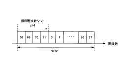
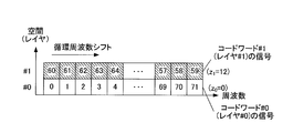
- the shift unit 301 of the terminal 300 cyclically shifts the SC-FDMA signal, which is the DFT output input from the DFT unit 110, by a cyclic frequency by z points within the DFT band.
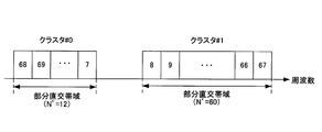
- division section 111 divides the SC-FDMA signal after the cyclic frequency shift by the partial orthogonal bandwidth according to any of the division methods described in Embodiment 1 or Embodiment 3, thereby dividing a plurality of clusters. Generate.
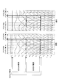
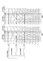
- FIGS. 18A to 18C a series of processing procedures in the shift unit 301 and the dividing unit 111 are shown in FIGS. 18A to 18C.
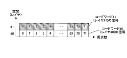
- FIG. 18A shows a 72-point DFT output (SC-FDMA signal) obtained after the DFT unit 110 performs DFT processing on the time-domain symbol sequence.
- the DFT output mapping flexibility can be improved on the frequency resources (subcarriers) while partially orthogonalizing the DFT matrix column vectors in the cluster.
- the terminal may shift the DFT output by a cyclic frequency before dividing the DFT output (SC-FDMA signal).
- SC-FDMA signal a cyclic frequency before dividing the DFT output
- the terminal can perform interference avoidance control without changing the position of the frequency resource allocated to the SC-FDMA signal.
- the direction of the circulating frequency shift may be either from a low frequency to a high frequency direction or from a high frequency to a low frequency direction. That is, the value of the circulating frequency shift amount z may be plus (+) or minus ( ⁇ ).
- the terminal according to the present invention may have a configuration (not shown) connected in the order of DFT unit ⁇ dividing unit ⁇ shift unit ⁇ mapping unit.
- the terminal shifts a plurality of subcarrier components belonging to each cluster through a cyclic frequency across a plurality of clusters (a plurality of divided clusters that are not subjected to a cyclic frequency shift).
- the same mapping as in FIG. 18C may be performed. Even when the connection order of the constituent parts of the terminal is changed in this way, the same effect as in the present embodiment can be obtained.
- the terminal uses the frequency domain signal output from the IFFT unit. It may be configured to multiply the phase rotation (and amplitude component) corresponding to the circulating frequency shift. That is, instead of the shift unit of the terminal shown in FIG. 15, a multiplier that multiplies the time domain signal output from the IFFT unit by the phase rotation (and amplitude component) corresponding to the cyclic frequency shift in the frequency domain, The structure (not shown) connected after this may be sufficient. Even in this case, the same effect as in the present embodiment can be obtained.
- the base station has a configuration (not shown) connected in the order of demapping unit ⁇ reverse shift unit ⁇ FDE unit ⁇ combining unit ⁇ IDFT unit, or demapping unit ⁇ FDE unit ⁇ reverse shift.
- the structure (not shown) connected in the order of the part ⁇ the coupling part ⁇ the IDFT part may be used.
- the base station shifts the signal sequence after demapping in the reverse shift unit in the reverse shift unit, and in the FDE unit
- the FDE weight may be subjected to the reverse circulation frequency cyclic shift, and the FDE may be performed on the demapped signal sequence after the reverse circulation frequency shift using the FDE weight after the reverse circulation frequency shift.
- the base station shifts the signal sequence after the FDE in the reverse shift unit and combines them. In the unit, a plurality of clusters after the reverse circulation frequency shift mapped to the discontinuous frequency band may be combined. Even when the connection order of the components of the base station is changed in this way, the same effects as in the present embodiment can be obtained.
- the time domain signal output from the IDFT unit of the base station is replaced with the frequency domain instead of the configuration (FIG. 16) for performing the reverse frequency shift of the frequency domain described in the present embodiment. It may be configured to multiply the phase rotation (and amplitude component) corresponding to the reverse circulation frequency shift. That is, instead of the inverse shift unit shown in FIG. 16, a multiplication unit that multiplies the time domain signal output from the IDFT unit by a phase rotation (and amplitude component) corresponding to the inverse frequency shift in the frequency domain, The structure (not shown) connected after this may be sufficient. Even in this case, the same effect as in the present embodiment can be obtained.
- the terminal when the terminal transmits the C-SC-FDMA signal in parallel in the frequency domain, the terminal, as shown in FIG. 19, the encoding unit, the modulation unit, the multiplexing unit, the DFT unit, the shift unit, and A plurality of units composed of division units may be provided. Then, the terminal may individually set an individual shift amount for each unit, and perform a cyclic frequency shift on the DFT output of each unit.
- M units 501-1 to 501-M are configured.
- M C-SC-FDMA signals are transmitted in parallel.
- C generated in each unit in a radio channel having different radio wave propagation environments in different frequency bands, such as a wideband radio channel having many multipaths and having frequency selectivity.
- mapping of the signals of each unit on the frequency resource (subcarrier) is performed by performing individual cyclic frequency shift for each unit while partially orthogonalizing between the column vectors of the DFT matrix. The flexibility can be improved.
- the cyclic frequency shift amount may be shared among a plurality of units, and control information regarding one common cyclic frequency shift amount may be notified from the base station to the terminal (or from the terminal to the base station).
- the individual cyclic frequency shift amount for each unit may be set to the same value, and control information regarding the cyclic frequency shift amount of each unit may be simultaneously notified from the base station to the terminal (or from the terminal to the base station).
- the same transmission format for example, the same MCS set or the same C-SC-FDMA division method (number of clusters or cluster size)
- the required communication between the units There is a correlation in quality (eg, SINR required to meet a certain error rate).
- the circulating frequency shift amount common among a plurality of units (that is, the same circulating frequency shift amount)
- the correlation of the required communication quality between the units can be further enhanced, and the transmission of the plurality of units is performed.
- the format can be controlled stably at the same time. Further, when one common cyclic frequency shift amount is used, the amount of information required for notification of the cyclic frequency shift amount from the base station to the terminal (or from the terminal to the base station) can be reduced.
- the above cyclic frequency shift amount setting method (the same cyclic frequency among a plurality of units) is used.
- a method of setting the frequency shift amount) may be applied. That is, by setting the same cyclic frequency shift amount among a plurality of units (that is, by using the same setting method regarding the cyclic frequency shift), an error generation mechanism for each of the transport blocks of the plurality of units is provided. Correlation can be provided. Accordingly, it is possible to reduce the probability that a transport block in which an error occurs and a transport block in which an error does not occur are mixed between transport blocks of a plurality of units. Retransmission can be reduced.
- the value of the cyclic frequency shift amount z with respect to the DFT output output from the DFT section of the terminal is a partially orthogonal vector corresponding to any of the division methods described in the first or fourth embodiment. You may set to the same value as the length satisfying the length (bandwidth).
- the partial orthogonality condition similar to the partial orthogonality condition for the SC-FDMA signal (spectrum) before the cyclic frequency shift can be applied to the SC-FDMA signal (spectrum) after the cyclic frequency shift. .
- the cyclic frequency shift amount z may be associated with the minimum division unit when the SC-FDMA signal (spectrum) is divided.
- the minimum division unit of the SC-FDMA signal (spectrum) is defined as N min
- the minimum shift amount of the cyclic frequency shift amount z may be N min as well.
- the minimum shift amount N min is shared between the transmission / reception apparatuses (terminal and base station), and a multiple kN min (k is an integer) of the minimum shift amount may be defined as the cyclic frequency shift amount z to be given to the DFT output.
- control information regarding the cyclic frequency shift amount z notified from the base station to the terminal may be only the multiplier (coefficient) k. Further, when the control information (multiplier k) regarding the cyclic frequency shift amount z is notified, the cyclic frequency shift amount k may be notified together with the cluster division information (division number or the like) or the frequency resource allocation information. Thereby, the information amount required for notification of the circulating frequency shift amount can be reduced.
- the amount of cyclic frequency shift is determined between the C-SC-FDMA signals transmitted in parallel (for example, as shown in FIG. 19). It may be defined relatively between the units 501-1 to 501-M of the terminal 500. Specifically, the shift amount of the difference between the cyclic frequency shift amount of the reference C-SC-FDMA signal and the cyclic frequency shift amount of another C-SC-FDMA signal is expressed as a relative shift amount (difference shift amount). And the relative shift amount (difference shift amount) may be notified from the base station to the terminal (or from the terminal to the base station).
- a case of setting 10 will be described.
- the cyclic frequency shift amount z 0 of the C-SC-FDMA signal mapped to the reference low frequency band 5
- the difference (relative value) between the cyclic frequency shift amount of the C-SC-FDMA signal mapped to the low frequency band and the cyclic frequency shift amount of the C-SC-FDMA signal mapped to the high frequency band z 1
- It is sufficient to notify ⁇ z 0 5. This can reduce the overhead of the amount of information required for notification of the cyclic frequency shift amount, compared to the case of individually reporting the cyclic frequency shift amount for each C-SC-FDMA signal.
- the number of C-SC-FDMA signals to be transmitted in parallel is not limited to two, but is three or more. But you can.
- terminals that perform MIMO transmission mutually communicate SC-FDMA signals transmitted in different spatial resources (layers, antennas, or streams) to which a plurality of codewords are mapped.
- an individual cyclic frequency shift is performed within the DFT band.
- the terminal divides the signal of each spatial resource (layer, antenna or stream) by a partial orthogonal bandwidth (bandwidth corresponding to a partially orthogonal vector length).
- FIG. 20 shows the configuration of the transmission apparatus (terminal) according to the present embodiment.
- terminal 600 shown in FIG. 20 the same components as in Embodiment 2 (FIG. 9) are assigned the same reference numerals, and descriptions thereof are omitted.
- terminal 600 shown in FIG. 20 includes two antennas that transmit C-SC-FDMA signals using two spatial resources.
- the terminal 600 shown in FIG. 20 is different from the terminal 200 (FIG. 9) of the second embodiment in that a C-SC-FDMA processing unit that generates an SC-FDMA signal (spectrum) transmitted in each spatial resource.
- an individual shift unit 301 is provided for each bit sequence (codeword) transmitted in parallel using a spatial resource.
- the control unit 106 outputs individual cyclic frequency shift amounts respectively corresponding to the C-SC-FDMA processing units 601 to the shift units 301.
- the individual cyclic frequency shift amount for the C-SC-FDMA processing unit 601 is determined by the base station, and the determined cyclic frequency shift amount is notified from the base station to the terminal, or the terminal It is assumed that the determined cyclic frequency shift amount is notified from the terminal to the base station.
- C-SC-FDMA processing units 601-1 and 601-2 perform the same processing as that of encoding unit 107 to DFT unit 110 of the second embodiment for each codeword (transmission bit sequence) input thereto. As a result, an SC-FDMA signal (spectrum) is generated. Then, each DFT section 110 of C-SC-FDMA processing sections 601-1 and 601-2 outputs the generated SC-FDMA signal (spectrum) to each shift section 301.
- Shift section 301 is input from DFT section 110 in the same manner as in the fifth embodiment in accordance with the cyclic frequency shift amount for each codeword input from control section 106 (that is, for each C-SC-FDMA processing section). An individual cyclic frequency shift is applied to the SC-FDMA signal (spectrum) for each C-SC-FDMA processing unit. Shift section 301 then outputs the SC-FDMA signal (spectrum) after the cyclic frequency shift to dividing section 111.
- Dividing section 111 uses SC-FDMA after cyclic frequency shift input from shifting section 301 using any of the dividing methods described in the above-described embodiments (for example, Embodiment 1 or Embodiment 4).
- a signal (spectrum) is divided by a partial orthogonal bandwidth to generate a plurality of clusters.
- the dividing unit 111 of each C-SC-FDMA processing unit 601 outputs the generated plurality of clusters to the precoding unit 202.
- terminal 600 converts two codewords (codeword # 0 and codeword # 1) into two different spatial resources (here, layer # 0 and layer # 1). # 1, or a case of mapping to an antenna or a stream) will be described.
- DFT size N 72 points (DFT output numbers 0 to 71)
- terminal 600 generates two clusters (cluster # 0 and cluster # 1).
- the shift unit 301 cyclically shifts the DFT output from the lower frequency to the higher frequency.
- FIG. 21A shows a 72-point DFT obtained after each DFT unit 110 of C-SC-FDMA processing units 601-1 and 601-2 performs DFT processing on two codewords # 0 and # 1, respectively.
- the output (SC-FDMA signal) is shown.
- the shift units 301 of the C-SC-FDMA processing units 601-1 and 601-2 respectively correspond to the two SC-FDMA signals (code word # 0 signal and code word # 1 signal) shown in FIG. 21A.
- the shift unit 301 of the C-SC-FDMA processing unit 601-1 performs the process for the codeword # 0 signal transmitted in the layer # 0 (spatial resource # 0).
- Z 0 (no cyclic frequency shift) is applied. Further, as shown in FIG.
- a circulation frequency shift of 12 (with a circulation frequency shift) is performed. That is, shift section 301 circulates within the DFT band for each of a plurality of spatial resources (layers, antennas or streams) for a codeword (SC-FDMA signal) transmitted in each of the plurality of layers (spatial resources). Apply frequency shift.
- Antenna or stream) frequency mapping adapted to each channel (link) quality can be flexibly performed for each codeword (for each spatial resource, for each layer, for each antenna or for each stream).
- SU-MIMO that realizes MIMO transmission by using a plurality of antennas in the transmission / reception apparatus (terminal and base station) has been described as an example.
- the present invention can also be applied to MU-MIMO for uplink and downlink.
- different codewords mapped to different spatial resources are codewords addressed to different terminals.
- different required quality must be satisfied for each receiving device (terminal).
- the communication quality of terminals (reception devices) located at different locations is greatly different.
- the transmission apparatus uses different spatial resources (layers, antennas, or streams) to which a plurality of codewords are mapped.
- a separate cyclic frequency shift is applied to each transmitted codeword.
- frequency mapping (circulation frequency shift) adapted to the quality of each channel (link) of the spatial resource in which the codeword is transmitted is maintained for each codeword (with the partial orthogonal relationship maintained within each codeword cluster. This can be performed flexibly for each spatial resource, each layer, each antenna, or each stream.
- the transmission apparatus may apply three or more codewords to three or more spatial resources (layer, antenna or stream).
- the cyclic frequency shift amount z i individually set for each codeword (for each layer, for each antenna, or for each stream), and the minimum division unit for dividing the SC-FDMA signal (spectrum) You may associate.
- the minimum division unit of the SC-FDMA signal (spectrum) is defined as N min
- the individual cyclic frequency shift amount z i set for each codeword (for each spatial resource, for each layer or for each stream) Similarly, the minimum shift amount may be N min . This makes it possible to apply the partial orthogonal condition similar to the partial orthogonal condition for the SC-FDMA signal (spectrum) before the cyclic frequency shift to all the clusters after the cyclic frequency shift.
- the cyclic frequency shift amount z i individually set for each codeword is set to the minimum among a plurality of clusters generated by dividing the SC-FDMA signal. It is good also as a multiple of the cluster size which has a partial orthogonal bandwidth. That is, the cyclic frequency shift amount z i may be associated with the bandwidth of the cluster having the minimum partial orthogonal bandwidth. For example, when the cluster size having the minimum partial orthogonal bandwidth in a certain spatial resource (layer, antenna or stream) is B min , the cyclic frequency shift amount in that spatial resource and another spatial resource is kB min (k is (Integer). Thereby, a (partial) orthogonal relationship in the frequency domain can be maintained between spatial resources (layers, antennas or streams), and interference from different clusters of different spatial resources can be reduced.
- cyclic frequency shift amounts individually set for each codeword for each spatial resource, for each layer, for each antenna, or for each stream
- the cyclic frequency shift amount set individually for each codeword is changed between codewords (between spatial resources, between layers, between antennas or streams). Relative).
- the overhead of the information amount required for notification of the cyclic frequency shift amount can be reduced as compared with the case where the cyclic frequency shift amount of each codeword (spatial resource, layer, antenna or stream) is individually notified.
- the number of code words is not limited to two and may be three or more.
- the cyclic frequency shift amount may be shared among a plurality of codewords (spatial resources, layers, antennas or streams), and one common cyclic frequency shift amount may be used. Further, the same cyclic frequency shift amount may be set between a plurality of codewords (spatial resources, layers, antennas or streams).
- each codeword (spatial resource, layer, antenna) (Or stream) cyclic frequency shift amount is set to the same value (or using one common cyclic frequency shift), and the cyclic frequency shift amount is notified from the base station to the terminal (or from the terminal to the base station). May be.
- codewords mapped to a plurality of spatial resources (layers, antennas or streams) having substantially the same required quality can be controlled stably at the same time.
- one common cyclic frequency shift amount is used, the amount of information required for notification of the cyclic frequency shift amount from the base station to the terminal (or from the terminal to the base station) can be further reduced.
- the SC-FDMA signal of each stream is divided by the partial orthogonal bandwidth in MIMO transmission, and is mapped to a frequency band having the same partial orthogonal bandwidth (length) in each of the plurality of streams.
- a precoding method has been described in which the same signal is multiplied by the same spatial precoding matrix. Therefore, also in this embodiment, the transmission apparatus (terminal) performs the same partial orthogonality on the signals of a plurality of spatial resources (layers, antennas or streams) after the SC-FDMA signal has been cyclically shifted.
- a configuration may further be adopted in which a signal mapped to a frequency band having a bandwidth (length) is further multiplied by the same spatial precoding matrix. That is, the terminal according to the present invention may take a configuration in which the second embodiment and the present embodiment are combined. Thereby, the effect similar to each effect of Embodiment 2 and this Embodiment can be acquired.
- a transmission apparatus transmits a plurality of codewords in a plurality of layers
- one codeword is mapped to one spatial resource (layer) (that is, a codeword
- space resources layers
- the present invention may be applied to a case where a transmission device (terminal) maps one codeword to a plurality of spatial resources (layers) (for example, MIMO single codeword transmission).
- a terminal performs spatial multiplexing transmission of two codewords (codeword # 0 and codeword # 1) using four spatial resources (layers # 0 to # 3).
- the terminal maps the codeword # 0 signal (modulated signal) to two layers of layer # 0 and layer # 1, and the codeword # 1 signal (modulated signal) to layers # 2 and # 3. May be mapped to the two layers.
- the terminal may perform individual cyclic frequency shift on each codeword using the cyclic frequency shift amount individually set for each layer (spatial resource).
- the terminal may use the same cyclic frequency shift amount between a plurality of layers (spatial resources) to which one codeword is mapped.
- a case where the terminal performs spatial multiplexing transmission of two codewords (codeword # 0 and codeword # 1) using four layers (layers # 0 to # 3) will be described. To do.
- the terminal maps each codeword to two layers (spatial resources).
- the terminal sets the same cyclic frequency shift amount between layers (spatial resources) to which the same codeword is mapped. For example, as illustrated in FIG.
- the cyclic frequency shift is performed on the different modulation signals included in the same codeword mapped to different spatial resources (layers) using the same cyclic frequency shift amount.
- the apparent channel change amount can be made the same between the same codewords mapped to different spatial resources (layers). Therefore, the likelihood distribution of bits or symbols in the codeword can be made uniform, and adaptive control such as adaptive modulation can be performed stably.
- the present invention may be configured such that the relative cyclic shift amounts in codewords mapped to different spatial resources (layers) are the same, and the relative cyclic shift amounts between codewords use different values. For example, when mapping two codewords (codeword # 0 and codeword # 1) to four spatial resources (layers # 0 to # 3), codeword # 0 maps to layer # 0 and layer # 1 A case where codeword # 1 is mapped to layer # 2 and layer # 3 will be described.
- the cyclic frequency shift amount of the reference layer # 0 is set to 8
- the relative cyclic frequency shift amount in layer # 0 and layer # 1 to which the codeword # 0 is mapped is set to 5
- the cyclic frequency shift amount of layer # 0 is 8
- each code word between each code word A cyclic frequency shift amount suitable for the communication quality of each word can be set flexibly.
- a signal mapped to a plurality of layers may be used as a repetition signal.
- the terminal uses a copy (repetition signal) of a DFT output of codeword # 0 (or codeword # 1) to be mapped to layer # 0 (or layer # 2) as layer # 0 and layer #. 1 (or layer # 2 and layer # 3) may be mapped.
- the terminal performs, for each spatial resource, a plurality of DFT outputs (a plurality of codewords) transmitted in each of a plurality of spatial resources (layers). And a C-SC-FDMA signal generated by dividing a plurality of DFT outputs (a plurality of codewords) transmitted in each of a plurality of spatial resources (layers).
- the cluster is subjected to a cyclic space (layer) shift in a spatial region (between spatial resources) with a partial orthogonal bandwidth (for example, a cluster having a partial orthogonal bandwidth) as a unit.
- FIG. 23 shows the configuration of the transmission apparatus (terminal) according to the present embodiment.
- terminal 700 shown in FIG. 23 the same components as in Embodiment 6 (FIG. 20) are assigned the same reference numerals, and descriptions thereof are omitted.
- terminal 700 shown in FIG. 23 includes two antennas that transmit C-SC-FDMA signals using two spatial resources.
- frequency shift section 702 of C-SC-FDMA processing section 701 shown in FIG. 23 performs the same processing as shift section 301 of C-SC-FDMA processing section 601 in terminal 600 (FIG. 20) of Embodiment 6. Do. Therefore, terminal 700 shown in FIG. 23 is different from terminal 600 (FIG. 20) of Embodiment 6 in that space shift section 703 is provided between dividing section 111 and precoding section 202. .
- space shift section 703 receives, from control section 106, a shift amount (hereinafter referred to as a shift amount) in a spatial resource region (layer) for each partial orthogonal bandwidth (for example, a cluster having a partial orthogonal bandwidth). (Referred to as cyclic space shift amount).
- the spatial shift unit 703 is subjected to individual cyclic frequency shifts for each codeword (or for each layer) by each division unit 111 of the C-SC-FDMA processing unit 701 in the same manner as in the sixth embodiment.
- the C-SC-FDMA signal (a plurality of clusters) is input.
- the space shift unit 703 performs a cyclic space shift between the spatial resources (layers) on each cluster according to the individual cyclic space shift amount for each partial orthogonal bandwidth (cluster). Specifically, spatial shift section 703 divides codewords (SC-FDMA signals) transmitted in each of a plurality of spatial resources (layers) into C-SC-FDMA signals (multiple clusters) that are generated. On the other hand, cyclic space shift is performed in units of orthogonal bandwidth. Then, the space shift unit 703 outputs the cluster after the cyclic space shift to the precoding unit 202.
- SC-FDMA signals codewords
- C-SC-FDMA signals multiple clusters
- terminal 700 maps two codewords (codeword # 0 and codeword # 1) to two different spatial resources (here, layers). explain. Similarly to Embodiment 6, C-SC-FDMA processing units 701-1 and 701-2 of terminal 700 perform cyclic frequency shift on codeword # 1 and codeword # 2 shown in FIG. 21A. (FIG. 21B) The SC-FDMA signal after the cyclic frequency shift is divided by the partial orthogonal bandwidth to generate two clusters, cluster # 0 and cluster # 1 (FIG. 21C). That is, terminal 700 performs a cyclic shift of the one-dimensional domain in the frequency domain by the process shown in FIG. 21B.
- the spatial shift unit 703 performs partial orthogonal bandwidth units, that is, clusters having partial orthogonal bandwidths, for each cluster (cluster # 0 and cluster # 1) after the cyclic frequency shift. Each time, a cyclic spatial shift is applied between spatial resources (layers).
- the cyclic space shift amount for cluster # 0 0 (no cyclic space shift)
- the codeword # 0 signal is mapped to layer # 1
- the codeword # 1 signal is mapped to layer # 0. That is, the terminal 700 performs a cyclic shift of the one-dimensional region in the spatial region by the process shown in FIG.
- the terminal performs a cyclic spatial shift in units of partial orthogonal bandwidths, so that a partial orthogonal relationship between column vectors in the frequency domain is obtained. While maintaining, the frequency diversity effect and the space diversity effect can be further improved.
- terminal 700 shown in FIG. 23 performs a cyclic frequency shift in the frequency domain on the signal in frequency shift section 702, and then performs a spatial shift in the spatial domain in spatial shift section 703.
- the configuration to be applied has been described.
- the processing order of the cyclic frequency shift and the cyclic spatial shift in the terminal may be reversed. That is, the terminal according to the present invention may perform a cyclic frequency shift in the frequency domain after performing a cyclic space (layer) shift in the spatial domain on the signal.
- the terminal may perform only the cyclic space (layer) shift in the one-dimensional area of the spatial domain without performing the cyclic frequency shift of the frequency domain on the signal. That is, the terminal performs a cyclic space (layer) in units of partial orthogonal bandwidths for a C-SC-FDMA signal (a plurality of clusters) generated by dividing an SC-FDMA signal transmitted in each of a plurality of spatial resources. ) Shift may be applied. This corresponds to a case where the cyclic frequency shift amount in each spatial resource (layer) is all set to zero in the present embodiment in which cyclic shift is performed in the two-dimensional domain of the frequency domain and the spatial domain.
- the frequency shift unit 702 is omitted, and the DFT output (SC-FDMA signal) output from the DFT unit 110 is not shifted cyclically, and the division unit 111 is used as it is.
- the circulation space (layer) shift may be applied only between the two. As a result, the spatial diversity effect can be improved while maintaining a partial orthogonal relationship within the cluster in the frequency domain.
- FIG. 24 of the present embodiment a case has been described in which the terminal performs cyclic spatial shift between spatial resources for each cluster having a partial orthogonal bandwidth length for a plurality of clusters.
- a terminal is configured to have a plurality of clusters in a bandwidth (length) unit that is partially orthogonal with a length shorter than the cluster size (bandwidth narrower than the cluster bandwidth).
- a cyclic space (layer) shift may be performed between spatial resources.
- Circulation space shift amount 1 and 2) are applied. This can further improve spatial diversity by maintaining a partial orthogonal relationship between the column vectors in the frequency domain, while increasing the apparent channel randomness within the cluster by cyclic spatial shift. Can do.
- the partial orthogonal bandwidth is a unit of a frequency domain to which a cyclic space (layer) shift is performed.
- a multiple of the minimum partial orthogonal bandwidth among the bandwidths of a plurality of clusters may be used as the unit of the frequency region to which the cyclic space (layer) shift is performed.
- the minimum partial orthogonal bandwidth is B min
- the unit of the frequency domain to which the cyclic spatial shift is performed may be defined as kB min (k is an integer).
- the base station may determine the cyclic space shift amount in units of kB min and notify the terminal of the determined cyclic space shift amount.
- the unit of the frequency domain where the cyclic space (layer) shift is performed can be defined only by performing simple control using the bandwidths of a plurality of clusters, and the same as in the present embodiment. An effect can be obtained.
- the cyclic space shift amount y in the unit of the frequency domain to which the cyclic space (layer) shift is performed is the frequency domain in which the cyclic space (layer) shift is performed. It may be different for each unit. Further, the rotation direction of the circulation space (layer) shift may be plus (+) or minus ( ⁇ ). That is, the cyclic space shift amount may be + y or -y.
- two shift amounts may be set by associating the cyclic frequency shift amount z with the cyclic space shift amount y.
- the cyclic frequency shift amount z i of the layer #i may be represented by a function of the cyclic spatial shift amount y i of the cluster #i, and conversely, the cyclic spatial shift amount y i of the cluster #i is represented by the cycle of the layer #i It may be expressed as a function of the frequency shift amount z i .
- cyclic space shift amount z i (circulation frequency shift amount y i ) mod (number of layers) may be defined.
- mod indicates a modulo operation.
- the receiving device only notifies the transmitting device of the circulating frequency shift amount y i , and the transmitting device may specify the circulating space shift amount z i according to the above function.
- identification information (flag) indicating whether cyclic space shift is applied or identification information (flag) indicating whether cyclic frequency shift is applied is transmitted from the reception device (base station) to the transmission device (terminal). ), The two pieces of identification information (flags) are shared, and one-dimensional two-dimensional information indicating whether or not the cyclic spatial shift and the frequency shift are applied may be notified from the receiving device to the transmitting device. Good. This makes it possible to obtain a spatial diversity effect and a frequency diversity effect at the same time while reducing the amount of control information related to identification information.
- FIG. 24 and FIG. 25 when two clusters (cluster # 0 and cluster # 1) are mapped to non-contiguous frequency bands, the terminal is divided into frequency domain and spatial domain 2
- a method of performing a cyclic shift (two-dimensional shift) in a three-dimensional region or a method of performing a cyclic shift (one-dimensional shift) in a one-dimensional region of a spatial region has been described.
- the present invention can also be applied when a plurality of clusters are mapped to continuous frequency bands.
- the terminal when performing a two-dimensional shift in the frequency domain and the spatial domain, the terminal performs cyclic frequency shift on each of a plurality of DFT outputs in the frequency domain, and then described in Embodiment 1 and Embodiment 4.
- the DFT output of each spatial resource (layer) shifted by the cyclic frequency in units of the partial orthogonal bandwidth is cyclically (layer) shifted in the spatial domain (between spatial resources).
- the terminal may map the signal after the cyclic shift in the frequency domain and the spatial domain to the continuous frequency band of each spatial resource (layer).
- the terminal when performing one-dimensional shift of the spatial domain, the terminal performs partial orthogonal bandwidth (for example, partial orthogonal bandwidth) described in the first and fourth embodiments for a plurality of DFT outputs.
- partial orthogonal bandwidth for example, partial orthogonal bandwidth
- a cyclic space (layer) is shifted in a spatial region (between spatial resources). Thereafter, the signal after the cyclic spatial shift may be mapped to the continuous frequency band of each spatial resource (layer).
- the terminal maintains a mapping position (frequency band) in the frequency domain of two clusters (cluster # 0 and cluster # 1),
- the circulation frequency shift amount z 0 0 at time # 0 at time # 0
- the circulation frequency shift amount z 1 12 at time # 1
- the circulation frequency shift amount z 2 at time # 2.
- the circulation frequency shift amount z 3 60.
- the terminal shifts the cyclic frequency with respect to the DFT output (SC-FDMA signal) using different cyclic frequency shift amounts in the DFT band (72 points) in different time domains (for different time resources). Apply. Then, as shown in FIG. 26, the terminal divides the DFT output after the cyclic frequency shift by the partial orthogonal bandwidth to generate two clusters # 0 and cluster # 1.
- the cluster is maintained without changing the frequency band to which the DFT output (SC-FDMA signal) is allocated (while maintaining the mapping position (frequency band) in the frequency domain).
- the time diversity effect and the frequency diversity effect can be improved while maintaining the partial orthogonality between the column vectors of the DFT matrix.
- the cyclic frequency shift amount may be changed using a symbol unit, a slot unit, a subframe unit, a frame unit, a retransmission unit, or the like as a time unit.
- the terminal divides the DFT output (SC-FDMA signal) by a length (bandwidth) partially orthogonal between the column vectors.
- the DFT matrix is a symmetric matrix.
- each element of the nth column vector of the N ⁇ N DFT matrix is the same as each element of the nth row vector. Therefore, in the present invention, even when a matrix obtained by transposing a DFT matrix is used as a precoding matrix, the terminal divides the precoded signal with a length (bandwidth) partially orthogonal between the row vectors of the DFT matrix. do it.
- the SC-FDMA signal division method described in the above embodiment may be applied to a signal precoded by a transposed matrix of the DFT matrix.
- a matrix obtained by transposing a DFT matrix is used as a precoding matrix, the same effect as in the above embodiment can be obtained.
- a complex conjugate matrix of a DFT matrix or a complex conjugate transpose matrix of a DFT matrix may be used as a precoding matrix.
- the complex conjugate matrix of the DFT matrix and the complex conjugate transpose matrix of the DFT matrix are symmetric matrices. Therefore, each element of the n-th column vector of the complex conjugate matrix (or complex conjugate transpose matrix (Hermitian transpose matrix of DFT matrix)) of the N ⁇ N DFT matrix is the same as each element of the n-th row vector. It is.
- Equation (1) and Equation (2) can be applied to the complex conjugate transpose matrix of the DFT matrix (Hermitian transpose matrix of the DFT matrix)
- the terminal What is necessary is just to divide the precoded signal by the length (bandwidth) which is partially orthogonal as described in the embodiment. That is, the SC-FDMA signal division method described in the above embodiment for a signal precoded by a complex conjugate matrix of a DFT matrix or a complex conjugate transpose matrix of a DFT matrix (Hermitian transpose matrix of a DFT matrix) Should be applied.
- the complex conjugate matrix of the DFT matrix or the complex conjugate transpose matrix of the DFT matrix (Hermitian transpose matrix of the DFT matrix) is used as the precoding matrix, the same effect as the above embodiment can be obtained.
- an inverse matrix of the DFT matrix may be used as the precoding matrix.
- the inverse matrix of the DFT matrix is equivalent to the complex conjugate transpose matrix of the DFT matrix (Hermitian transpose matrix of the DFT matrix). Therefore, when the inverse matrix of the DFT matrix is used as the precoding matrix, the SC-FDMA signal division method described in the above embodiment is applied to the signal precoded with the inverse matrix of the DFT matrix. Good. Thereby, even when the inverse matrix of the DFT matrix is used as the precoding matrix, the same effect as in the above embodiment can be obtained.
- the terminal configuration for example, FIG. 9 and FIG. 20
- the terminal may be connected in the order of DFT unit ⁇ precoding unit ⁇ dividing unit.
- the terminal converts each transmission symbol sequence in which the pilot signal is multiplexed into a signal from the time domain to the frequency domain by DFT processing in the DFT unit, and then converts each signal into each subcarrier signal in the frequency domain in the precoding unit.
- linear precoding is performed (for example, a precoding matrix represented by a matrix is multiplied by two DFT output signals in a certain subcarrier). Then, the terminal may perform the division process on the SC-FDMA signal with respect to the frequency domain signal component after precoding by the division unit by any of the division methods of the above embodiment.
- the SC-FDMA signal is divided by the partial orthogonal bandwidth in the frequency domain.
- the DFT matrix DFT matrix transposed matrix, DFT matrix complex conjugate matrix, DFT matrix
- the signal may be spread using a complex conjugate transpose matrix or an inverse matrix of a DFT matrix, and applied to MIMO transmission in which the spread signal is code-multiplexed in the spatial domain.
- the obtained signal may be divided by the partial orthogonal bandwidth, and the divided signals may be mapped to discontinuous time resources or spatial resources, respectively. Thereby, the effect similar to the said embodiment can be acquired.
- Embodiments 1 to 8 may be used in combination.
- the wireless communication apparatus is a terminal 100 (FIG. 1), a terminal 200 (FIG. 9), a terminal 300 (FIG. 15), a terminal 500 (FIG. 19), and a terminal 600 (FIG. 20).
- a terminal 100 FIG. 1
- a terminal 200 FIG. 9
- a terminal 300 FIG. 15
- a terminal 500 FIG. 19
- a terminal 600 FIG. 20
- the terminal is sometimes referred to as UE (User Equipment: UE), and the base station is referred to as Node B or BS (Base Station).
- UE User Equipment
- BS Base Station
- the antenna is described as an antenna.
- the present invention can be similarly applied to an antenna port.
- An antenna port refers to a logical antenna composed of one or more physical antennas. That is, the antenna port does not necessarily indicate one physical antenna, but may indicate an array antenna composed of a plurality of antennas.
- 3GPP LTE it is not defined how many physical antennas an antenna port is composed of, but is defined as a minimum unit in which a base station can transmit different reference signals (Reference signals).
- the antenna port may be defined as a minimum unit for multiplying the weight of a precoding vector (Precoding vector).
- each functional block used in the description of the above embodiment is typically realized as an LSI which is an integrated circuit. These may be individually made into one chip, or may be made into one chip so as to include a part or all of them.
- the name used here is LSI, but it may also be called IC, system LSI, super LSI, or ultra LSI depending on the degree of integration.
- the method of circuit integration is not limited to LSI, and implementation with a dedicated circuit or a general-purpose processor is also possible.
- An FPGA Field Programmable Gate Array
- a reconfigurable processor that can reconfigure the connection and setting of circuit cells inside the LSI may be used.
- the present invention can be applied to a mobile communication system or the like.
Landscapes
- Engineering & Computer Science (AREA)
- Signal Processing (AREA)
- Computer Networks & Wireless Communication (AREA)
- Physics & Mathematics (AREA)
- General Physics & Mathematics (AREA)
- Mathematical Physics (AREA)
- Discrete Mathematics (AREA)
- Pure & Applied Mathematics (AREA)
- Mathematical Analysis (AREA)
- Mathematical Optimization (AREA)
- Computational Mathematics (AREA)
- Theoretical Computer Science (AREA)
- Data Mining & Analysis (AREA)
- Software Systems (AREA)
- Databases & Information Systems (AREA)
- General Engineering & Computer Science (AREA)
- Algebra (AREA)
- Mobile Radio Communication Systems (AREA)
- Radio Transmission System (AREA)
- Digital Transmission Methods That Use Modulated Carrier Waves (AREA)
- Transmitters (AREA)
Abstract
Description
本実施の形態に係る端末100の構成を図1に示す。


本分割方法では、分割部111は、式(1)より算出されるベクトル長N’に対応する部分直交帯域幅B’(=N’*Bsub)でSC-FDMA信号を分割する。
本分割方法では、分割部111は、式(1)において、(|I|/|i-i’|)-1が2以上N未満であり、かつ、Nの約数のいずれか1つであるベクトル長N’に対応する部分直交帯域幅B’でSC-FDMA信号を分割する。
本分割方法では、分割部111は、素数の倍数であるベクトル長N’に対応する部分直交帯域幅B’でSC-FDMA信号を分割する。
本分割方法では、分割部111は、素数のべき乗であるベクトル長N’に対応する部分直交帯域幅B’でSC-FDMA信号を分割する。
本実施の形態では、高速大容量のデータ伝送を実現するための伝送技術の1つであるMIMO(Multi-Input Multi-Output)伝送を用いる場合について説明する。MIMO伝送技術では、基地局および端末の双方に複数のアンテナを設け、無線送受信間の空間に複数の伝搬路(ストリーム)を用意し、各ストリームを空間的に多重することにより、スループットを増大させることができる。
実施の形態2では、FSTD(Frequency Switched Transmit Diversity)を用いる場合、端末が、部分直交する帯域幅を有する周波数帯域(またはクラスタ)毎に送信アンテナを切り替える場合について説明した。また、このとき、全ての送信アンテナの周波数領域で見ると、非連続な周波数帯域に複数のクラスタがマッピングされる場合について説明した。これに対して、本実施の形態では、端末は、部分直交する帯域幅を有する周波数帯域(またはクラスタ)毎に送信アンテナを切り替えるFSTDを用いる場合において、全ての送信アンテナの周波数領域で見た場合に、連続する周波数帯域に複数のクラスタをマッピングする。
実施の形態1の<分割方法1-4>では、分割部111(図1)は、以下に示す(1)~(5)のベクトル長N’に対応する部分直交帯域幅B’でSC-FDMA信号を分割する場合について説明した。
(1)素数x0のべき乗:
N’=x0 a0(ただし、a0は1以上の整数)
(2)素数x0,x1,x2,…のうち少なくとも2つの素数(2つ以上の素数)の積のべき乗:
N’=(x0*x1)b0(ただし、b0は1以上の整数)
(3)素数x0、x1、x2、…のうち少なくとも2つの素数(2つ以上の素数)の積のべき乗の倍数:
N’=p0(x0*x1)b0(ただし、p0は1以上の整数)
(4)素数x0、x1、…のべき乗x0 c0、x1 c1、…(c0、c1、…は0以上の整数。ただし、c0、c1、…のうち少なくとも1つは1以上の整数)のうち少なくとも2つ(2つ以上)の積:
N’=x0 c0*x1 c1*…
(5)素数のべき乗の積x0 c0*x1 c1*…の倍数:
N’=p0(x0 c0*x1 c1*…)(ただし、p0は1以上の整数)
実施の形態1および実施の形態4では、図1に示すように、端末のDFT部に分割部が接続され、DFT部の出力信号(DFT出力)を上述した分割方法により直接分割することにより、複数のクラスタを生成する場合について説明した。これに対し、本実施の形態は、DFT部と分割部との間にシフト部を設ける場合について説明する。具体的には、本実施の形態に係る端末は、シフト部においてDFT部から出力されるDFT出力(SC-FDMA信号(スペクトラム))を循環的に周波数シフト(循環周波数シフト)させて、循環周波数シフト後のSC-FDMA信号を部分直交帯域幅(長さ)に分割して、複数のクラスタを生成する。

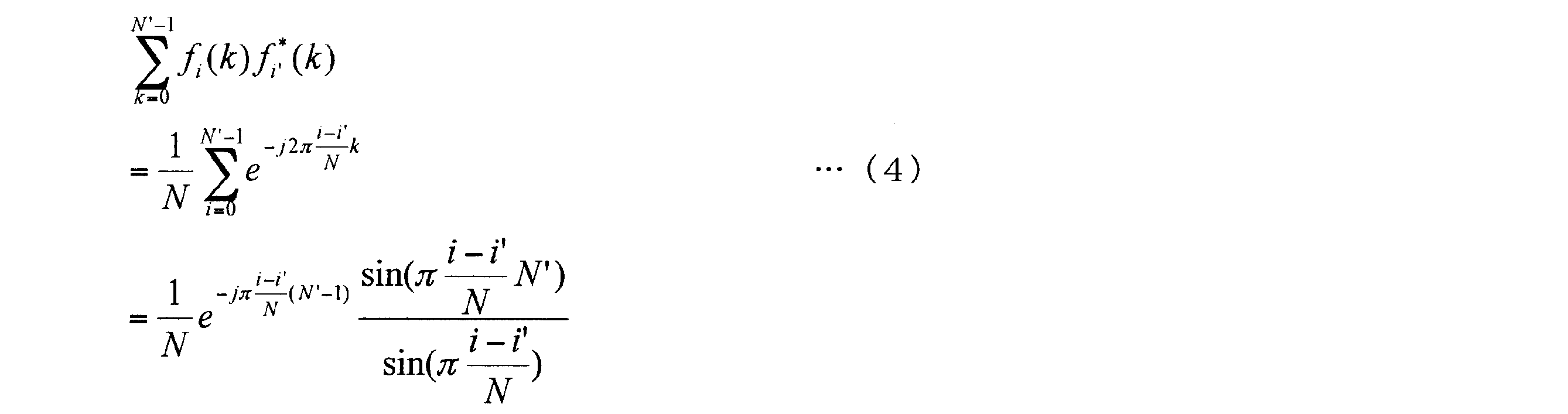

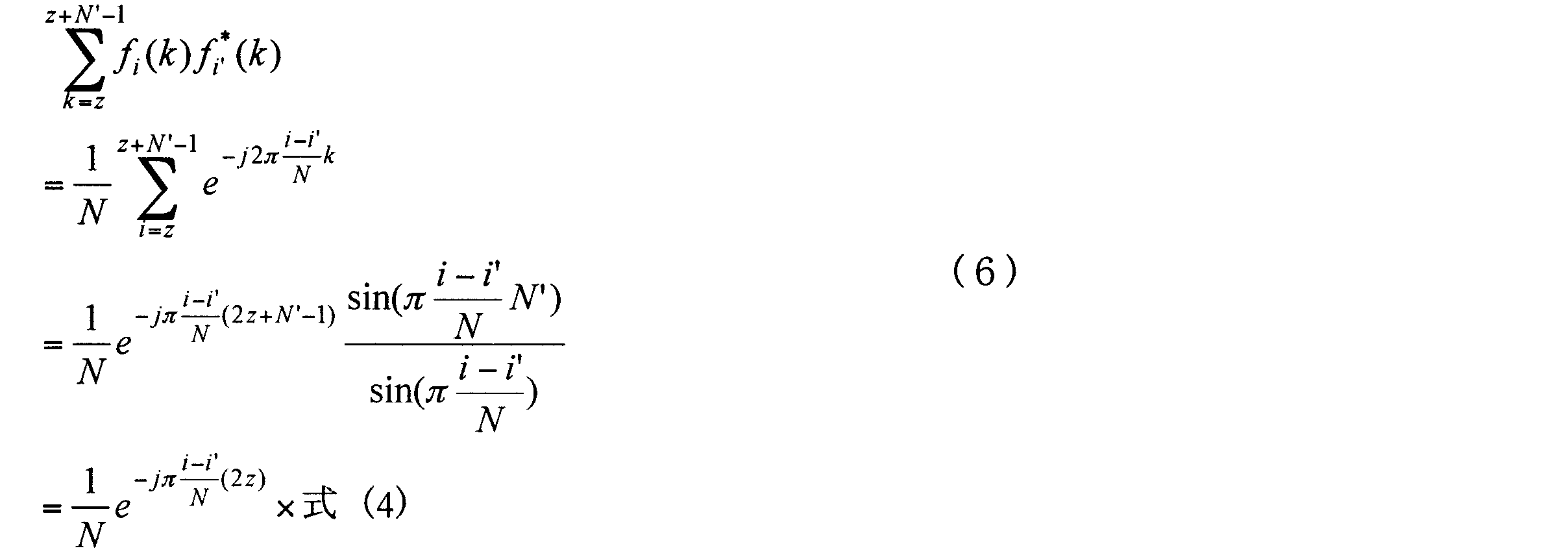
本実施の形態では、MIMO伝送を行う端末は、複数のコードワード(codeword)がマッピングされる、互いに異なる空間リソース(レイヤ、アンテナまたはストリーム)それぞれにおいて送信されるSC-FDMA信号に対して、互いに異なる空間リソース毎に、DFT帯域内で個別の循環周波数シフトを施す。そして、端末は、各空間リソース(レイヤ、アンテナまたはストリーム)の信号を部分直交帯域幅(部分直交するベクトル長に対応する帯域幅)で分割する。
実施の形態6では、端末が、各空間リソース(レイヤ)において、周波数領域のみの1次元領域で、空間リソース毎に個別の循環周波数シフトを行う場合について説明した。これに対し、本実施の形態では、端末が、周波数領域の循環シフトに加えて、空間領域の循環シフトを行うことにより、空間領域および周波数領域の2次元領域で循環(空間および周波数)シフトを行う点が実施の形態6と相違する。
実施の形態5では、端末が、DFT出力(SC-FDMA信号)に対して、空間リソース(レイヤ)毎に、個別の循環周波数シフトを行う場合について説明した。これに対し、本実施の形態では、端末は、DFT出力(SC-FDMA信号)に対して、互いに異なる時間領域で(異なる時間リソース毎に)、DFT帯域内で個別の循環周波数シフトを施す。そして、端末は、循環周波数シフト後の信号を部分直交帯域幅で分割することにより、複数のクラスタを生成する。
Claims (20)
- DFT行列を用いて、時間領域のシンボル系列にDFT処理を施して、周波数領域の信号を生成する変換手段と、
前記DFT行列を構成する複数の列ベクトルのうち、いずれかが部分直交するベクトル長に対応する部分直交帯域幅で前記信号を分割して、複数のクラスタを生成する分割手段と、
前記複数のクラスタを、不連続な複数の周波数帯域にそれぞれマッピングするマッピング手段と、
を具備する無線通信装置。 - 前記分割手段は、式(1)より算出される前記ベクトル長N’に対応する前記部分直交帯域幅で前記信号を分割する、
請求項1記載の無線通信装置。

- 前記分割手段は、式(2)より算出される前記部分直交帯域幅B’で前記信号を分割する、
請求項2記載の無線通信装置。

- 前記分割手段は、前記式(1)において、(|I|/|i-i’|)-1が2以上前記N未満であり、かつ、前記Nの約数のいずれか1つである前記ベクトル長N’に対応する前記部分直交帯域幅で前記信号を分割する、
請求項2記載の無線通信装置。 - 前記分割手段は、素数の倍数である前記ベクトル長N’に対応する前記部分直交帯域幅で前記信号を分割する、
請求項2記載の無線通信装置。 - 前記分割手段は、2つ以上の素数の積の倍数である前記ベクトル長N’に対応する前記部分直交帯域幅で前記信号を分割する、
請求項2記載の無線通信装置。 - 前記分割手段は、素数のべき乗である前記ベクトル長N’に対応する前記部分直交帯域幅で前記信号を分割する、
請求項2記載の無線通信装置。 - 前記分割手段は、2つ以上の素数の積のべき乗である前記ベクトル長N’に対応する前記部分直交帯域幅で前記信号を分割する、
請求項2記載の無線通信装置。 - 前記分割手段は、素数のべき乗の積である前記ベクトル長N’に対応する前記部分直交帯域幅で前記信号を分割する、
請求項2記載の無線通信装置。 - 複数のストリームを用いて前記信号を送信する複数のアンテナと、
前記複数のストリームそれぞれにおいて、同一の前記部分直交帯域幅を有する周波数帯域にマッピングされる前記信号に同一の空間プレコーディング行列をそれぞれ乗算するプレコーディング手段と、をさらに具備する、
請求項1記載の無線通信装置。 - 前記プレコーディング手段は、前記複数のストリームそれぞれにおいて、前記複数のクラスタのうち、同一の前記部分直交帯域幅を有するクラスタに同一の前記空間プレコーディング行列をそれぞれ乗算する、
請求項10記載の無線通信装置。 - 前記分割手段は、前記ベクトル長N’を表すべき乗の積を構成する複数のべき乗相互において、あるべき乗の指数の値が、前記あるべき乗の底よりも小さい底を有する他のべき乗の指数の値以下となり、前記あるべき乗の底よりも大きい底を有する他のべき乗の指数の値以上となる、前記ベクトル長N’に対応する前記部分直交帯域幅で前記信号を分割する、
請求項9記載の無線通信装置。 - 前記分割手段は、前記ベクトル長N’を最小分割単位とし、前記最小分割単位の倍数に対応する前記部分直交帯域幅で前記信号を分割する、
請求項12記載の無線通信装置。 - 前記分割手段は、前記最小分割単位を表すべき乗の積を構成する複数のべき乗の底の組み合わせと同一の底の組み合わせを用いたべき乗の積で表される乗数を、前記最小分割単位に乗じて算出した、前記倍数に対応する前記部分直交帯域幅で前記信号を分割する、
請求項13記載の無線通信装置。 - 前記分割手段は、前記乗数を表すべき乗の積を構成する複数のべき乗相互において、あるべき乗の指数の値が、前記あるべき乗の底よりも小さい底を有する他のべき乗の指数の値以下となり、前記あるべき乗の底よりも大きい底を有する他のべき乗の指数の値以上となる、前記乗数を前記最小分割単位に乗じて算出した前記倍数に対応する前記部分直交帯域幅で前記信号を分割する、
請求項14記載の無線通信装置。 - 前記周波数領域の信号に対して、前記DFT処理におけるDFT帯域内で循環周波数シフトを施すシフト手段、をさらに具備する、
請求項1記載の無線通信装置。 - 複数の空間リソースを用いて前記信号を送信する複数のアンテナと、
前記複数の空間リソースそれぞれにおいて送信される前記信号に対して、前記複数の空間リソース毎に、前記DFT処理におけるDFT帯域内で循環周波数シフトを施すシフト手段と、をさらに具備する、
請求項1記載の無線通信装置。 - 複数の空間リソースを用いて前記信号を送信する複数のアンテナと、
前記複数の空間リソースそれぞれにおいて送信される前記信号に対して、前記複数の空間リソース毎に、前記DFT処理におけるDFT帯域内で循環周波数シフトを施す周波数シフト手段と、
前記複数の空間リソースそれぞれにおいて送信される前記信号を分割して生成される前記複数のクラスタに対して、前記部分直交帯域幅単位で循環空間シフトを施す空間シフト手段と、をさらに具備する、
請求項1記載の無線通信装置。 - 複数の空間リソースを用いて前記信号を送信する複数のアンテナと、
前記複数の空間リソースそれぞれにおいて送信される前記信号を分割して生成される前記複数のクラスタに対して、前記部分直交帯域幅単位で循環空間シフトを施す空間シフト手段と、をさらに具備する、
請求項1記載の無線通信装置。 - 時間領域のシンボル系列を周波数領域の信号に変換するために用いるDFT行列を構成する複数の列ベクトルのうち、いずれかが部分直交するベクトル長に対応する部分直交周波数帯域幅で前記信号を分割して、複数のクラスタを生成する、
信号分割方法。
Priority Applications (23)
| Application Number | Priority Date | Filing Date | Title |
|---|---|---|---|
| EP13175490.5A EP2651057B1 (en) | 2008-09-22 | 2009-09-18 | Clustered SC-FDMA radio communication device and method |
| CN200980136109.5A CN102160310B (zh) | 2008-09-22 | 2009-09-18 | 无线通信装置及信号分割方法 |
| MX2011003075A MX2011003075A (es) | 2008-09-22 | 2009-09-18 | Dispositivo de radiocomunicacion y metodo de division de señales. |
| EP13175493.9A EP2651058B1 (en) | 2008-09-22 | 2009-09-18 | Clustered SC-FDMA radio communication device and method |
| EP09814327.4A EP2330762B1 (en) | 2008-09-22 | 2009-09-18 | Radio communication device and signal division method |
| KR1020127012665A KR101658776B1 (ko) | 2008-09-22 | 2009-09-18 | 통신 장치 및 통신 방법 |
| RU2011110719/07A RU2516457C2 (ru) | 2008-09-22 | 2009-09-18 | Устройство радиосвязи и способ разделения сигналов |
| US13/119,813 US8605571B2 (en) | 2008-09-22 | 2009-09-18 | Radio communication device and signal division method |
| KR1020117005981A KR101766489B1 (ko) | 2008-09-22 | 2009-09-18 | 통신 장치 및 통신 방법 |
| JP2010529649A JP5236000B2 (ja) | 2008-09-22 | 2009-09-18 | 通信装置および通信方法 |
| BRPI0914194A BRPI0914194B8 (pt) | 2008-09-22 | 2009-09-18 | Aparelho e método de comunicação |
| US14/072,668 US9042213B2 (en) | 2008-09-22 | 2013-11-05 | Communication apparatus and a communication method for combining signals mapped on a plurality of frequency bands and transforming the combined signal into a symbol in a time domain |
| US14/694,960 US9258075B2 (en) | 2008-09-22 | 2015-04-23 | Communication apparatus and communication method for discrete-fourier-transforming a time domain symbol to a frequency domain signal and mapping the transformed signal on frequency bands |
| US14/979,109 US9516648B2 (en) | 2008-09-22 | 2015-12-22 | Communication apparatus and communication method for inverse discrete-fourier-transforming a frequency domain signal into a time domain symbol sequence |
| US15/337,985 US9775155B2 (en) | 2008-09-22 | 2016-10-28 | Integrated circuit that transforms a symbol in a time domain into a signal in a frequency domain |
| US15/678,948 US10028281B2 (en) | 2008-09-22 | 2017-08-16 | Integrated circuit for inverse discrete fourier transforming a frequency domain signal to a time domain symbol sequence |
| US16/012,519 US10178674B2 (en) | 2008-09-22 | 2018-06-19 | Communication apparatus and method for discrete fourier transforming a time domain symbol to a frequency domain signal |
| US16/209,172 US10484994B2 (en) | 2008-09-22 | 2018-12-04 | Apparatus and method for transforming a signal in a frequency domain to a sequence in a time domain |
| US16/596,199 US10743315B2 (en) | 2008-09-22 | 2019-10-08 | Communication system for transforming signals between time domain and frequency domain using a defined discrete fourier transform size |
| US16/910,466 US11013004B2 (en) | 2008-09-22 | 2020-06-24 | Communication apparatus and method for Discrete Fourier Transforming a time signal to a frequency signal |
| US17/232,856 US11575552B2 (en) | 2008-09-22 | 2021-04-16 | Communication apparatus and method for discrete fourier transforming a time signal to a frequency signal |
| US18/149,620 US11929858B2 (en) | 2008-09-22 | 2023-01-03 | Integrated circuit for Discrete Fourier Transforming a time signal to a frequency signal |
| US18/433,076 US20240179037A1 (en) | 2008-09-22 | 2024-02-05 | Integrated circuit for discrete fourier transforming a time signal to a frequency signal |
Applications Claiming Priority (4)
| Application Number | Priority Date | Filing Date | Title |
|---|---|---|---|
| JP2008-242716 | 2008-09-22 | ||
| JP2008242716 | 2008-09-22 | ||
| JP2009201740 | 2009-09-01 | ||
| JP2009-201740 | 2009-09-01 |
Related Child Applications (2)
| Application Number | Title | Priority Date | Filing Date |
|---|---|---|---|
| US13/119,813 A-371-Of-International US8605571B2 (en) | 2008-09-22 | 2009-09-18 | Radio communication device and signal division method |
| US14/072,668 Continuation US9042213B2 (en) | 2008-09-22 | 2013-11-05 | Communication apparatus and a communication method for combining signals mapped on a plurality of frequency bands and transforming the combined signal into a symbol in a time domain |
Publications (1)
| Publication Number | Publication Date |
|---|---|
| WO2010032482A1 true WO2010032482A1 (ja) | 2010-03-25 |
Family
ID=42039329
Family Applications (1)
| Application Number | Title | Priority Date | Filing Date |
|---|---|---|---|
| PCT/JP2009/004741 Ceased WO2010032482A1 (ja) | 2008-09-22 | 2009-09-18 | 無線通信装置および信号分割方法 |
Country Status (9)
| Country | Link |
|---|---|
| US (13) | US8605571B2 (ja) |
| EP (3) | EP2651057B1 (ja) |
| JP (3) | JP5236000B2 (ja) |
| KR (2) | KR101658776B1 (ja) |
| CN (2) | CN102160310B (ja) |
| BR (1) | BRPI0914194B8 (ja) |
| MX (1) | MX2011003075A (ja) |
| RU (1) | RU2516457C2 (ja) |
| WO (1) | WO2010032482A1 (ja) |
Cited By (8)
| Publication number | Priority date | Publication date | Assignee | Title |
|---|---|---|---|---|
| JP2012019425A (ja) * | 2010-07-09 | 2012-01-26 | Mitsubishi Electric Corp | 無線通信システムならびに送信装置および受信装置 |
| JPWO2010050383A1 (ja) * | 2008-10-31 | 2012-03-29 | シャープ株式会社 | 送信装置、受信装置および通信システム |
| CN103270713A (zh) * | 2011-01-07 | 2013-08-28 | 松下电器产业株式会社 | 发送装置、接收装置、发送方法以及接收方法 |
| JP2014507872A (ja) * | 2011-01-20 | 2014-03-27 | ▲ホア▼▲ウェイ▼技術有限公司 | 直交周波数分割多重システムにおける離散スペクトルの使用、ならびに離散スペクトルを使用する受信方法および装置 |
| JP2014507845A (ja) * | 2011-01-06 | 2014-03-27 | マーベル ワールド トレード リミテッド | Wlanマルチ無線デバイスのための巡回シフト遅延 |
| JP2015156672A (ja) * | 2008-11-14 | 2015-08-27 | パナソニック インテレクチュアル プロパティ コーポレーション オブアメリカPanasonic Intellectual Property Corporation of America | 端末装置、マッピング方法及び集積回路 |
| JP2018511194A (ja) * | 2015-01-23 | 2018-04-19 | 日本テキサス・インスツルメンツ株式会社 | 2つのdftプリコーディング段を用いるsc−fdmaのための送信方式 |
| JP2023502761A (ja) * | 2019-11-22 | 2023-01-25 | ホアウェイ・テクノロジーズ・カンパニー・リミテッド | 無線通信の柔軟なフレーム構成 |
Families Citing this family (36)
| Publication number | Priority date | Publication date | Assignee | Title |
|---|---|---|---|---|
| JP2762743B2 (ja) | 1990-12-06 | 1998-06-04 | 日立電線株式会社 | 電力ケーブル接続部における導体接続方法 |
| EP2651057B1 (en) * | 2008-09-22 | 2020-07-22 | Sun Patent Trust | Clustered SC-FDMA radio communication device and method |
| CN102006144B (zh) * | 2009-09-01 | 2014-01-08 | 华为技术有限公司 | 预编码方法、装置及频域均衡方法、装置 |
| CN102237945A (zh) | 2010-05-06 | 2011-11-09 | 松下电器产业株式会社 | 基于正交编码的码分复用方法、码分复用设备和解复用设备 |
| CN103460663B (zh) * | 2011-01-27 | 2016-08-17 | 联邦科学技术研究组织 | 减少带外发射 |
| US20130188579A1 (en) * | 2012-01-23 | 2013-07-25 | Qualcomm Incorporated | Mimo/xpic receiver |
| EP2904867B1 (en) * | 2012-10-05 | 2019-05-22 | Sierra Wireless, Inc. | Method and system for radio resource allocation |
| GB201222552D0 (en) * | 2012-12-14 | 2013-01-30 | Sony Corp | Data processing apparatus and method |
| KR20150002316A (ko) * | 2013-06-28 | 2015-01-07 | 삼성전기주식회사 | 무선 통신 장치 및 이를 이용한 운용 방법 |
| IL227401B (en) * | 2013-07-09 | 2018-10-31 | Verint Systems Ltd | A system and method for passive wireless monitoring with effective channel allocation |
| JP5551298B1 (ja) * | 2013-09-12 | 2014-07-16 | ソフトバンクモバイル株式会社 | 電波強度測定装置及びプログラム |
| JP5976850B2 (ja) * | 2015-01-07 | 2016-08-24 | 日本電信電話株式会社 | 受信方法、受信装置および無線通信方法 |
| WO2016209056A1 (ko) | 2015-06-26 | 2016-12-29 | 엘지전자 주식회사 | 무선 통신 시스템에서 장치 대 장치 통신 단말의 신호 송수신 방법 및 장치 |
| MX376588B (es) * | 2015-08-21 | 2025-03-07 | Ericsson Telefon Ab L M | Comunicacion de los datos no-ip sobre redes de datos por paquetes. |
| CN105762945B (zh) * | 2016-05-12 | 2018-09-21 | 重庆大学 | 用于ecpt系统中的复合信源式电能与信号并行传输方法 |
| CN107645464B (zh) | 2016-07-22 | 2022-08-19 | 中兴通讯股份有限公司 | 多载波系统及多载波系统的数据调制、解调方法及装置 |
| AU2017310256B2 (en) * | 2016-08-08 | 2022-05-26 | Whipbird Signals Pty Ltd | Orthogonal precoding for sidelobe suppression |
| TWI672010B (zh) * | 2017-04-26 | 2019-09-11 | 大陸商貴州濎通芯物聯技術有限公司 | 多重循環頻移正交分頻多工之展頻裝置 |
| TWI696359B (zh) * | 2017-05-19 | 2020-06-11 | 大陸商貴州濎通芯物聯技術有限公司 | 循環頻移正交分頻多工存取之展頻裝置 |
| CN111226404B (zh) * | 2017-07-31 | 2022-05-03 | 弗劳恩霍夫应用研究促进协会 | 无线通信网络以及发射机和接收机 |
| US10142038B1 (en) * | 2017-08-11 | 2018-11-27 | Rohde & Schwarz Gmbh & Co. Kg | MIMO signal generator with frequency multiplexing |
| TWI730284B (zh) * | 2018-01-22 | 2021-06-11 | 日商瑞笛思股份有限公司 | 接收方法、接收裝置、傳送方法、傳送裝置、傳送接收系統 |
| SG11201902729VA (en) | 2018-01-22 | 2019-08-27 | Radius Co Ltd | Receiver method, receiver, transmission method, transmitter, and transmitter-receiver system |
| EP3588882A1 (en) | 2018-06-29 | 2020-01-01 | Nxp B.V. | Automatic gain control sc-fdma symbol partial use for decoding |
| JP7193717B2 (ja) * | 2018-12-11 | 2022-12-21 | 日本電信電話株式会社 | 光伝送システム、光送信機、光受信機及び伝達関数推定方法 |
| CN112533295B (zh) * | 2019-01-09 | 2021-11-19 | 华为技术有限公司 | 参数配置方法和通信装置 |
| US12224828B2 (en) | 2019-02-14 | 2025-02-11 | Apple Inc. | Method of type II CSI reporting for multiple spatial layers |
| WO2020244728A1 (en) * | 2019-06-03 | 2020-12-10 | Nokia Technologies Oy | Dynamic discrete fourier transform or bandwidth size indication |
| CN112243271B (zh) * | 2019-07-16 | 2023-11-24 | 大唐移动通信设备有限公司 | 一种信号处理方法、设备及装置 |
| WO2021150463A1 (en) * | 2020-01-21 | 2021-07-29 | Comsonics, Inc. | Leakage detection for cable tv systems with upstream signals above 118 mhz |
| US12130340B2 (en) | 2020-01-21 | 2024-10-29 | Comsonics, Inc. | Leakage detection for cable TV systems with upstream signals above 118 MHz |
| RU2763163C1 (ru) * | 2020-11-26 | 2021-12-28 | Федеральное государственное унитарное предприятие Центральный научно-исследовательский институт связи (ФГУП ЦНИИС) | Способ неортогонального множественного доступа на основе парциального кодирования |
| CN112637709B (zh) * | 2020-12-17 | 2022-08-19 | 郑州轻工业大学 | 弹性光网络中的基于频谱资源素数划分的频谱分配方法 |
| US11804892B2 (en) * | 2021-10-07 | 2023-10-31 | Tj Innovation Co., Ltd. | Distributed antenna system with hybrid signal sources |
| US12382414B2 (en) * | 2022-12-02 | 2025-08-05 | Qualcomm Incorporated | Compensation of uplink timing errors for non-terrestrial networks |
| JP2026086129A (ja) * | 2024-11-14 | 2026-05-26 | ソニーグループ株式会社 | 基地局、端末装置、及び、通信方法 |
Citations (3)
| Publication number | Priority date | Publication date | Assignee | Title |
|---|---|---|---|---|
| WO2008081876A1 (ja) * | 2006-12-28 | 2008-07-10 | Sharp Kabushiki Kaisha | 無線送信装置、制御装置、無線通信システムおよび通信方法 |
| JP2008242716A (ja) | 2007-03-27 | 2008-10-09 | Hitachi Software Eng Co Ltd | 改修項目調査漏れ防止支援システム |
| JP2009201740A (ja) | 2008-02-28 | 2009-09-10 | Aruze Corp | 遊技機 |
Family Cites Families (26)
| Publication number | Priority date | Publication date | Assignee | Title |
|---|---|---|---|---|
| US3925648A (en) * | 1974-07-11 | 1975-12-09 | Us Navy | Apparatus for the generation of a high capacity chirp-Z transform |
| DE3246743C1 (de) * | 1982-12-17 | 1984-07-05 | Philips Kommunikations Industrie AG, 8500 Nürnberg | Verfahren zur Verteilung der Verkehrsmenge auf verschiedene Organisationskanaele eines Funkuebetragungssystems |
| US7165252B1 (en) * | 1999-06-21 | 2007-01-16 | Jia Xu | Method of scheduling executions of processes with various types of timing properties and constraints |
| US7421029B2 (en) * | 2002-12-20 | 2008-09-02 | Unique Broadband Systems, Inc. | Impulse response shortening and symbol synchronization in OFDM communication systems |
| KR100689382B1 (ko) * | 2003-06-20 | 2007-03-02 | 삼성전자주식회사 | 직교분할다중화방식을 기반으로 하는이동통신시스템에서의 송신장치 및 방법 |
| RU2256931C1 (ru) | 2004-02-24 | 2005-07-20 | Открытое акционерное общество "Альметьевский завод "Радиоприбор" | Устройство для измерения состава и расхода многокомпонентной жидкости на основе ядерного магнитного резонанса (варианты) |
| RU2256934C1 (ru) | 2004-03-04 | 2005-07-20 | Открытое акционерное общество "Корпорация "Фазотрон-Научно-исследовательский институт радиостроения" | Способ спектрально-временной трансформации сигналов |
| JP4687948B2 (ja) * | 2004-10-29 | 2011-05-25 | ソニー株式会社 | ディジタル信号処理装置、ディジタル信号処理方法及びプログラム並びに認証装置 |
| WO2007048278A1 (en) * | 2005-10-28 | 2007-05-03 | Huawei Technologies Co., Ltd. | A method for peak-to-average power ratio reduction |
| US7940640B2 (en) * | 2006-01-20 | 2011-05-10 | Nortel Networks Limited | Adaptive orthogonal scheduling for virtual MIMO system |
| JP4946159B2 (ja) * | 2006-05-09 | 2012-06-06 | 富士通株式会社 | 無線送信方法及び無線受信方法並びに無線送信装置及び無線受信装置 |
| US20080040214A1 (en) * | 2006-08-10 | 2008-02-14 | Ip Commerce | System and method for subsidizing payment transaction costs through online advertising |
| CN1909545B (zh) * | 2006-08-17 | 2010-12-01 | 华为技术有限公司 | 分集发送信号的方法及其装置 |
| US8929300B2 (en) * | 2006-08-18 | 2015-01-06 | Panasonic Intellectual Property Corporation Of America | Radio communication base station device and control channel arranging method |
| KR101226819B1 (ko) * | 2006-08-21 | 2013-01-25 | 삼성전자주식회사 | 광대역 무선 통신 시스템에서 역방향 접근채널의 프리앰블송수신 방법 및 장치 |
| EP1895731A1 (en) | 2006-08-28 | 2008-03-05 | Nokia Siemens Networks Gmbh & Co. Kg | Method for generating an SC-FDMA radio signal for transmission, method for receiving the signal as well as corresponding transmitter and receiver |
| US8259773B2 (en) * | 2006-10-31 | 2012-09-04 | Alcatel Lucent | Method and apparatus for multiplexing code division multiple access and single carrier frequency division multiple access transmissions |
| CN101039502B (zh) * | 2007-03-22 | 2012-12-05 | 中兴通讯股份有限公司 | 一种mbms中配置多载频的方法及系统 |
| WO2009022462A1 (ja) * | 2007-08-10 | 2009-02-19 | Panasonic Corporation | 端末装置及び基地局装置 |
| KR101417084B1 (ko) * | 2008-07-02 | 2014-08-07 | 엘지전자 주식회사 | 상향링크 전송을 위한 기준신호 전송 방법 |
| KR101527008B1 (ko) * | 2008-07-07 | 2015-06-09 | 엘지전자 주식회사 | 부분 주파수 재사용을 위한 제어 정보 제공 방법 |
| JP2010045442A (ja) * | 2008-08-08 | 2010-02-25 | Sharp Corp | 無線通信システム、スケジューリング方法、通信装置およびプログラム |
| JP5244184B2 (ja) * | 2008-08-08 | 2013-07-24 | シャープ株式会社 | 無線通信システム、送信装置、受信装置 |
| EP2651057B1 (en) * | 2008-09-22 | 2020-07-22 | Sun Patent Trust | Clustered SC-FDMA radio communication device and method |
| RU2525084C2 (ru) * | 2008-11-14 | 2014-08-10 | Панасоник Корпорэйшн | Устройство терминала беспроводной связи, устройство базовой станции беспроводной связи и способ установки констелляции кластеров |
| US11013044B2 (en) * | 2017-01-13 | 2021-05-18 | Lg Electronics Inc. | Proximity-based wireless communication method and user equipment |
-
2009
- 2009-09-18 EP EP13175490.5A patent/EP2651057B1/en active Active
- 2009-09-18 WO PCT/JP2009/004741 patent/WO2010032482A1/ja not_active Ceased
- 2009-09-18 CN CN200980136109.5A patent/CN102160310B/zh active Active
- 2009-09-18 US US13/119,813 patent/US8605571B2/en active Active
- 2009-09-18 RU RU2011110719/07A patent/RU2516457C2/ru active
- 2009-09-18 BR BRPI0914194A patent/BRPI0914194B8/pt active IP Right Grant
- 2009-09-18 MX MX2011003075A patent/MX2011003075A/es active IP Right Grant
- 2009-09-18 KR KR1020127012665A patent/KR101658776B1/ko active Active
- 2009-09-18 CN CN201410197194.9A patent/CN103929292B/zh active Active
- 2009-09-18 EP EP13175493.9A patent/EP2651058B1/en active Active
- 2009-09-18 JP JP2010529649A patent/JP5236000B2/ja active Active
- 2009-09-18 EP EP09814327.4A patent/EP2330762B1/en active Active
- 2009-09-18 KR KR1020117005981A patent/KR101766489B1/ko active Active
-
2013
- 2013-03-22 JP JP2013059790A patent/JP5619205B2/ja active Active
- 2013-11-05 US US14/072,668 patent/US9042213B2/en active Active
-
2014
- 2014-09-12 JP JP2014186207A patent/JP5827734B2/ja active Active
-
2015
- 2015-04-23 US US14/694,960 patent/US9258075B2/en active Active
- 2015-12-22 US US14/979,109 patent/US9516648B2/en active Active
-
2016
- 2016-10-28 US US15/337,985 patent/US9775155B2/en active Active
-
2017
- 2017-08-16 US US15/678,948 patent/US10028281B2/en active Active
-
2018
- 2018-06-19 US US16/012,519 patent/US10178674B2/en active Active
- 2018-12-04 US US16/209,172 patent/US10484994B2/en active Active
-
2019
- 2019-10-08 US US16/596,199 patent/US10743315B2/en active Active
-
2020
- 2020-06-24 US US16/910,466 patent/US11013004B2/en active Active
-
2021
- 2021-04-16 US US17/232,856 patent/US11575552B2/en active Active
-
2023
- 2023-01-03 US US18/149,620 patent/US11929858B2/en active Active
-
2024
- 2024-02-05 US US18/433,076 patent/US20240179037A1/en active Pending
Patent Citations (3)
| Publication number | Priority date | Publication date | Assignee | Title |
|---|---|---|---|---|
| WO2008081876A1 (ja) * | 2006-12-28 | 2008-07-10 | Sharp Kabushiki Kaisha | 無線送信装置、制御装置、無線通信システムおよび通信方法 |
| JP2008242716A (ja) | 2007-03-27 | 2008-10-09 | Hitachi Software Eng Co Ltd | 改修項目調査漏れ防止支援システム |
| JP2009201740A (ja) | 2008-02-28 | 2009-09-10 | Aruze Corp | 遊技機 |
Non-Patent Citations (9)
| Title |
|---|
| ALCATEL-LUCENT SHANGHAI BELL ET AL.: "Codeword Shifting for Clustered DFT-S-OFDM and N x DFT-S-OFDM for LTE-Advanced Uplink SU-MIMO", 3GPP TSG RAN WG1 MEETING #57BIS RL-092313, 29 June 2009 (2009-06-29), pages 1 - 5, XP050350844 * |
| ERICSSON: "Summary of email discussion on Uplink transmission scheme", TSG-RAN WG1 #55 RL-084375, 10 November 2008 (2008-11-10), pages 1 - 6, XP050317643 * |
| HIDEO NANBA ET AL.: "PAPR o Koryo shita Dynamic Spectrum Seigyo ni Kansuru Kento, B-5-50", PROCEEDINGS OF THE 2008 IEICE GENERAL CONFERENCE, TSUSHIN 1, 5 March 2008 (2008-03-05), pages 436, XP008145695 * |
| KEIGO MASHIMA ET AL.: "Dynamic Spectrum Seigyo o Mochiita Kotaiiki Single Carrier Denso Hoshiki ni Kansuru Kento", IEICE TECHNICAL REPORT, RCS2006-233, vol. 106, no. 480, 19 January 2007 (2007-01-19), pages 97 - 102, XP008139970 * |
| LG ELECTRONICS: "Uplink multiple access schemes for LTE-A", 3GPP TSG RAN WG1 #54 RL-082945, 18 August 2008 (2008-08-18), pages 1 - 12, XP050316411 * |
| NOKIA SIEMENS NETWORKS, NOKIA: "LTE-A Proposals for evolution", RAN WG1 #53 RI-081842, 5 May 2008 (2008-05-05), pages 1 - 10, XP008143087 * |
| NORTEL: "Performance Evaluation of Multi-Antenna SC-FDMA in LTE-A", 3GPP TSG-RAN WG1#55 RL-084471, 10 November 2008 (2008-11-10), pages 1 - 3, XP050317725 * |
| PANASONIC: "Consideration on Multicarrier Transmission scheme for LTE-Adv uplink", 3GPP TSG RAN WG1 MEETING #53BIS RL-082398, - 30 June 2008 (2008-06-30), pages 1 - 3, XP050110679 * |
| See also references of EP2330762A4 |
Cited By (17)
| Publication number | Priority date | Publication date | Assignee | Title |
|---|---|---|---|---|
| JPWO2010050383A1 (ja) * | 2008-10-31 | 2012-03-29 | シャープ株式会社 | 送信装置、受信装置および通信システム |
| JP2015156672A (ja) * | 2008-11-14 | 2015-08-27 | パナソニック インテレクチュアル プロパティ コーポレーション オブアメリカPanasonic Intellectual Property Corporation of America | 端末装置、マッピング方法及び集積回路 |
| JP2012019425A (ja) * | 2010-07-09 | 2012-01-26 | Mitsubishi Electric Corp | 無線通信システムならびに送信装置および受信装置 |
| JP2014507845A (ja) * | 2011-01-06 | 2014-03-27 | マーベル ワールド トレード リミテッド | Wlanマルチ無線デバイスのための巡回シフト遅延 |
| US9553750B2 (en) | 2011-01-07 | 2017-01-24 | Sun Patent Trust | Transmitter, receiver, transmission method, and reception method |
| CN103270713B (zh) * | 2011-01-07 | 2015-10-14 | 松下电器(美国)知识产权公司 | 发送装置、接收装置、发送方法以及接收方法 |
| CN103270713A (zh) * | 2011-01-07 | 2013-08-28 | 松下电器产业株式会社 | 发送装置、接收装置、发送方法以及接收方法 |
| US10251174B2 (en) | 2011-01-07 | 2019-04-02 | Sun Patent Trust | Transmitter, receiver, transmission method, and reception method |
| US11160076B2 (en) | 2011-01-07 | 2021-10-26 | Sun Patent Trust | Transmitter, receiver, transmission method, and reception method |
| US11582082B2 (en) | 2011-01-07 | 2023-02-14 | Sun Patent Trust | Transmitter, receiver, transmission method, and reception method |
| US11831483B2 (en) | 2011-01-07 | 2023-11-28 | Sun Patent Trust | Transmitter, receiver, transmission method, and reception method |
| US12057982B2 (en) | 2011-01-07 | 2024-08-06 | Sun Patent Trust | Transmitter, receiver, transmission method, and reception method |
| KR101521202B1 (ko) * | 2011-01-20 | 2015-05-18 | 후아웨이 테크놀러지 컴퍼니 리미티드 | 직교 주파수 분할 다중화 시스템에서의 이산 주파수 스펙트럼의 사용, 및 이산 주파수 스펙트럼을 이용하는 수신 방법 및 장치 |
| JP2014507872A (ja) * | 2011-01-20 | 2014-03-27 | ▲ホア▼▲ウェイ▼技術有限公司 | 直交周波数分割多重システムにおける離散スペクトルの使用、ならびに離散スペクトルを使用する受信方法および装置 |
| JP2018511194A (ja) * | 2015-01-23 | 2018-04-19 | 日本テキサス・インスツルメンツ株式会社 | 2つのdftプリコーディング段を用いるsc−fdmaのための送信方式 |
| JP2023502761A (ja) * | 2019-11-22 | 2023-01-25 | ホアウェイ・テクノロジーズ・カンパニー・リミテッド | 無線通信の柔軟なフレーム構成 |
| JP7562665B2 (ja) | 2019-11-22 | 2024-10-07 | ホアウェイ・テクノロジーズ・カンパニー・リミテッド | 無線通信の柔軟なフレーム構成 |
Also Published As
Similar Documents
| Publication | Publication Date | Title |
|---|---|---|
| JP5827734B2 (ja) | 通信装置および通信方法 | |
| TW201831016A (zh) | 無線裝置及用於無線通信系統之網路節點 | |
| US11343823B2 (en) | Orthogonal multiple access and non-orthogonal multiple access |
Legal Events
| Date | Code | Title | Description |
|---|---|---|---|
| WWE | Wipo information: entry into national phase |
Ref document number: 200980136109.5 Country of ref document: CN |
|
| 121 | Ep: the epo has been informed by wipo that ep was designated in this application |
Ref document number: 09814327 Country of ref document: EP Kind code of ref document: A1 |
|
| WWE | Wipo information: entry into national phase |
Ref document number: 2010529649 Country of ref document: JP |
|
| WWE | Wipo information: entry into national phase |
Ref document number: 406/MUMNP/2011 Country of ref document: IN |
|
| WWE | Wipo information: entry into national phase |
Ref document number: 2009814327 Country of ref document: EP |
|
| ENP | Entry into the national phase |
Ref document number: 20117005981 Country of ref document: KR Kind code of ref document: A |
|
| NENP | Non-entry into the national phase |
Ref country code: DE |
|
| WWE | Wipo information: entry into national phase |
Ref document number: MX/A/2011/003075 Country of ref document: MX |
|
| WWE | Wipo information: entry into national phase |
Ref document number: 2011110719 Country of ref document: RU |
|
| WWE | Wipo information: entry into national phase |
Ref document number: 13119813 Country of ref document: US |
|
| ENP | Entry into the national phase |
Ref document number: PI0914194 Country of ref document: BR Kind code of ref document: A2 Effective date: 20110322 |