WO2010032532A1 - 走行環境認識装置 - Google Patents
走行環境認識装置 Download PDFInfo
- Publication number
- WO2010032532A1 WO2010032532A1 PCT/JP2009/062020 JP2009062020W WO2010032532A1 WO 2010032532 A1 WO2010032532 A1 WO 2010032532A1 JP 2009062020 W JP2009062020 W JP 2009062020W WO 2010032532 A1 WO2010032532 A1 WO 2010032532A1
- Authority
- WO
- WIPO (PCT)
- Prior art keywords
- road
- road shape
- vehicle
- dimensional object
- environment recognition
- Prior art date
- Legal status (The legal status is an assumption and is not a legal conclusion. Google has not performed a legal analysis and makes no representation as to the accuracy of the status listed.)
- Ceased
Links
Images




Classifications
-
- G—PHYSICS
- G06—COMPUTING OR CALCULATING; COUNTING
- G06V—IMAGE OR VIDEO RECOGNITION OR UNDERSTANDING
- G06V20/00—Scenes; Scene-specific elements
- G06V20/50—Context or environment of the image
- G06V20/56—Context or environment of the image exterior to a vehicle by using sensors mounted on the vehicle
- G06V20/588—Recognition of the road, e.g. of lane markings; Recognition of the vehicle driving pattern in relation to the road
-
- B—PERFORMING OPERATIONS; TRANSPORTING
- B60—VEHICLES IN GENERAL
- B60W—CONJOINT CONTROL OF VEHICLE SUB-UNITS OF DIFFERENT TYPE OR DIFFERENT FUNCTION; CONTROL SYSTEMS SPECIALLY ADAPTED FOR HYBRID VEHICLES; ROAD VEHICLE DRIVE CONTROL SYSTEMS FOR PURPOSES NOT RELATED TO THE CONTROL OF A PARTICULAR SUB-UNIT
- B60W30/00—Purposes of road vehicle drive control systems not related to the control of a particular sub-unit, e.g. of systems using conjoint control of vehicle sub-units
- B60W30/14—Adaptive cruise control
-
- B—PERFORMING OPERATIONS; TRANSPORTING
- B60—VEHICLES IN GENERAL
- B60W—CONJOINT CONTROL OF VEHICLE SUB-UNITS OF DIFFERENT TYPE OR DIFFERENT FUNCTION; CONTROL SYSTEMS SPECIALLY ADAPTED FOR HYBRID VEHICLES; ROAD VEHICLE DRIVE CONTROL SYSTEMS FOR PURPOSES NOT RELATED TO THE CONTROL OF A PARTICULAR SUB-UNIT
- B60W30/00—Purposes of road vehicle drive control systems not related to the control of a particular sub-unit, e.g. of systems using conjoint control of vehicle sub-units
- B60W30/14—Adaptive cruise control
- B60W30/143—Speed control
-
- B—PERFORMING OPERATIONS; TRANSPORTING
- B60—VEHICLES IN GENERAL
- B60W—CONJOINT CONTROL OF VEHICLE SUB-UNITS OF DIFFERENT TYPE OR DIFFERENT FUNCTION; CONTROL SYSTEMS SPECIALLY ADAPTED FOR HYBRID VEHICLES; ROAD VEHICLE DRIVE CONTROL SYSTEMS FOR PURPOSES NOT RELATED TO THE CONTROL OF A PARTICULAR SUB-UNIT
- B60W30/00—Purposes of road vehicle drive control systems not related to the control of a particular sub-unit, e.g. of systems using conjoint control of vehicle sub-units
- B60W30/18—Propelling the vehicle
- B60W30/18009—Propelling the vehicle related to particular drive situations
- B60W30/18145—Cornering
-
- B—PERFORMING OPERATIONS; TRANSPORTING
- B60—VEHICLES IN GENERAL
- B60W—CONJOINT CONTROL OF VEHICLE SUB-UNITS OF DIFFERENT TYPE OR DIFFERENT FUNCTION; CONTROL SYSTEMS SPECIALLY ADAPTED FOR HYBRID VEHICLES; ROAD VEHICLE DRIVE CONTROL SYSTEMS FOR PURPOSES NOT RELATED TO THE CONTROL OF A PARTICULAR SUB-UNIT
- B60W40/00—Estimation or calculation of non-directly measurable driving parameters for road vehicle drive control systems not related to the control of a particular sub unit, e.g. by using mathematical models
- B60W40/02—Estimation or calculation of non-directly measurable driving parameters for road vehicle drive control systems not related to the control of a particular sub unit, e.g. by using mathematical models related to ambient conditions
- B60W40/06—Road conditions
- B60W40/072—Curvature of the road
-
- B—PERFORMING OPERATIONS; TRANSPORTING
- B60—VEHICLES IN GENERAL
- B60W—CONJOINT CONTROL OF VEHICLE SUB-UNITS OF DIFFERENT TYPE OR DIFFERENT FUNCTION; CONTROL SYSTEMS SPECIALLY ADAPTED FOR HYBRID VEHICLES; ROAD VEHICLE DRIVE CONTROL SYSTEMS FOR PURPOSES NOT RELATED TO THE CONTROL OF A PARTICULAR SUB-UNIT
- B60W40/00—Estimation or calculation of non-directly measurable driving parameters for road vehicle drive control systems not related to the control of a particular sub unit, e.g. by using mathematical models
- B60W40/02—Estimation or calculation of non-directly measurable driving parameters for road vehicle drive control systems not related to the control of a particular sub unit, e.g. by using mathematical models related to ambient conditions
- B60W40/06—Road conditions
- B60W40/076—Slope angle of the road
-
- G—PHYSICS
- G08—SIGNALLING
- G08G—TRAFFIC CONTROL SYSTEMS
- G08G1/00—Traffic control systems for road vehicles
- G08G1/16—Anti-collision systems
- G08G1/165—Anti-collision systems for passive traffic, e.g. including static obstacles, trees
-
- G—PHYSICS
- G08—SIGNALLING
- G08G—TRAFFIC CONTROL SYSTEMS
- G08G1/00—Traffic control systems for road vehicles
- G08G1/16—Anti-collision systems
- G08G1/167—Driving aids for lane monitoring, lane changing, e.g. blind spot detection
-
- B—PERFORMING OPERATIONS; TRANSPORTING
- B60—VEHICLES IN GENERAL
- B60W—CONJOINT CONTROL OF VEHICLE SUB-UNITS OF DIFFERENT TYPE OR DIFFERENT FUNCTION; CONTROL SYSTEMS SPECIALLY ADAPTED FOR HYBRID VEHICLES; ROAD VEHICLE DRIVE CONTROL SYSTEMS FOR PURPOSES NOT RELATED TO THE CONTROL OF A PARTICULAR SUB-UNIT
- B60W2420/00—Indexing codes relating to the type of sensors based on the principle of their operation
- B60W2420/40—Photo, light or radio wave sensitive means, e.g. infrared sensors
- B60W2420/403—Image sensing, e.g. optical camera
-
- B—PERFORMING OPERATIONS; TRANSPORTING
- B60—VEHICLES IN GENERAL
- B60W—CONJOINT CONTROL OF VEHICLE SUB-UNITS OF DIFFERENT TYPE OR DIFFERENT FUNCTION; CONTROL SYSTEMS SPECIALLY ADAPTED FOR HYBRID VEHICLES; ROAD VEHICLE DRIVE CONTROL SYSTEMS FOR PURPOSES NOT RELATED TO THE CONTROL OF A PARTICULAR SUB-UNIT
- B60W2552/00—Input parameters relating to infrastructure
- B60W2552/15—Road slope, i.e. the inclination of a road segment in the longitudinal direction
Definitions
- the present invention relates to a travel environment recognition device that recognizes a road shape.
- Adaptive cruise control which uses a radar or the like to control the speed of the host vehicle in accordance with the speed of the preceding vehicle.
- ACC Adaptive cruise control
- an ACC that uses a navigation system to detect a curve ahead of the vehicle and automatically decelerates by the curve has also been developed.
- the road shape detection error the road shape change due to construction.
- the control / warning timing is shifted due to the influence of the calculation error of the distance to the road shape such as the curve. For this reason, a technique for measuring the road shape in real time and with high accuracy becomes important.
- a stationary object is detected using millimeter wave radar, and only the stationary object that is effective for estimating the road shape is selected from the detected stationary objects using the previous processing result, the yaw rate sensor, or the steering angle sensor.
- the previous processing result the yaw rate sensor, or the steering angle sensor.
- there is a technique for estimating a curve see Patent Document 1.
- effective stationary objects are selected for each road shape assuming multiple road shapes, and the one with the most selected stationary objects is effective for estimating the road shape.
- Patent Document 1 since the method of Patent Document 1 only selects a three-dimensional object based on the road shape of the previous processing result, the road shape is erroneously estimated in the previous processing or when the road shape is discontinuous. There is a problem that it is difficult to estimate the road shape with high accuracy in the case of accidents. Also, instead of selecting a stationary object based on the previous road shape, a process of selecting a stationary object for a plurality of road shapes is performed, and the stationary object when the most selected stationary objects are large is effective. Therefore, it is necessary to perform a three-dimensional object selection process for a plurality of road shapes.
- an object of the present invention is to provide a traveling environment recognition device capable of estimating a road shape with high accuracy even in a distant place where objects constituting a road such as a lane or a curb are not visible.
- the travel environment recognition device includes a measurement unit that measures an object, an object detection unit that detects an object based on a signal acquired by the measurement unit, and a road shape prediction unit that predicts the shape of a road on which the vehicle travels.
- the solid object selection unit that selects only a three-dimensional object within a predetermined range from the road location predicted by the road shape prediction unit, and the solid object selection unit selected from the objects detected by the object detection unit.
- a road shape estimation unit that estimates the shape of the road based on the position information of the three-dimensional object.
- the present invention it is possible to provide a traveling environment recognition device capable of estimating a road shape with high accuracy even in a distant place where objects such as lanes and curbs are not visible.
- FIG. 1 is a functional block diagram of the traveling environment recognition device 1.
- FIG. 2 is a block diagram showing an in-vehicle system including a travel environment recognition device.
- FIG. 3 is a diagram showing the principle of a stereo camera.
- FIG. 4 is a flowchart of the driving environment recognition function.
- FIG. 5 is a diagram showing a coordinate system of a three-dimensional position of an object.
- FIG. 6 is a diagram showing a process of estimating a curve shape by a series of processes of a traveling environment recognition function.
- FIG. 7 is a diagram showing a process of estimating a road gradient by a series of processes of a traveling environment recognition function.
- FIG. 8 is a diagram showing an example in which the shape of a curve is represented by a combination of two straight lines.
- FIG. 8 is a diagram showing an example in which the shape of a curve is represented by a combination of two straight lines.
- FIG. 9 is a diagram showing an example in which the shape of a curve is represented by a curve.
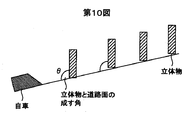
- FIG. 10 is a diagram showing a method for calculating the road gradient even when the vehicle is traveling.
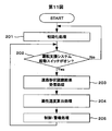
- FIG. 11 is a flowchart of the vehicle control function and alarm function of the control unit.
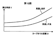
- FIG. 12 is a diagram showing a method for calculating the appropriate speed of the control unit.
- FIG. 13 is a diagram showing a method for calculating the appropriate speed of the control unit.
- FIG. 14 is a diagram showing a method for calculating the appropriate speed of the control unit.
- FIG. 15 is a diagram showing a method for calculating the appropriate speed of the control unit.
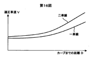
- FIG. 16 is a diagram showing a method for calculating the appropriate speed of the control unit.
- the travel environment recognition apparatus 1 is configured by a measurement apparatus shown in FIG. 1 including two cameras, and is applied to the travel environment recognition apparatus 1 as shown in FIG.
- the travel environment recognition device 1 realizes a function of recognizing the environment around the vehicle by the camera (imaging unit) 4a and the camera 4b. At this time, three or more cameras may be provided. Further, the control unit 2 separate from the camera or an image processing unit (not shown) may capture and process images from the cameras 4a and 4b.
- the driving environment recognition device 1 uses the difference in appearance (hereinafter referred to as parallax) that occurs when the same measurement point is imaged by a plurality of cameras as shown in FIG. It is the structure which can obtain
- the distance Z can be obtained by Equation 1.
- the travel environment recognition device 1 is mounted on a vehicle and applied to an in-vehicle system 3 shown in FIG.
- the traveling environment recognition device 1 detects a lane and a three-dimensional object existing in front of the vehicle (hereinafter referred to as the own vehicle), transmits the detected lane and a three-dimensional object to the control unit 2, and controls the vehicle based on the detection result. Or a device for notifying the passenger of the danger.
- the driving environment recognition apparatus 1 includes a CPU 6, a RAM 9, a program ROM 10, and a data ROM 7.
- the control unit 2 includes a CPU 12, a RAM 11, a program ROM 14, and a data ROM 13.
- the traveling environment recognition device 1 and the control unit 2 are connected, and further, a display 15 that is installed in the passenger compartment and displays various images and various information, and the vehicle is an obstacle.
- a speaker 19 that generates a warning sound when there is a risk of collision, an ignition switch 20 that is turned on when the engine is started, and a start switch that starts the system are connected, and display control of the display 15 is started.
- the control unit 2 controls the operation of the entire in-vehicle system.
- the traveling environment recognition device 1 is attached to, for example, a room mirror in the own vehicle compartment, and images the state in front of the own vehicle at a predetermined depression angle and attachment position.
- An image in front of the host vehicle (hereinafter referred to as a captured image) captured by the camera 4a and the camera 4b is taken into the RAM 9 inside the traveling environment recognition device 1 to detect a lane and a three-dimensional object in front of the host vehicle and to form a road shape.
- the display 15 is composed of a display device such as an LCD (Liquid Crystal Display), for example. Under display control by the control unit 2, for example, an image of a travel route guidance by a navigation system (not shown), an image of the travel environment recognition device 1, etc. Various images of are displayed.
- LCD Liquid Crystal Display
- the display 15 displays a message for informing that a sharp curve or the like exists under the control of the control unit 2.
- the control unit 2 has a configuration in which a CPU 12, a RAM 11, a data ROM 13 and a program ROM 14 are connected via a bus, and the CPU 12 executes various control programs stored in the program ROM 14 to control the operation of the entire system. .
- a driving environment recognition program for detecting a lane, a three-dimensional object, etc. and estimating a road shape is stored in the program ROM 10, and when the engine is started, the CPU 6 executes these programs.
- the traveling environment recognition function is realized and functions as an object detection unit 31, a road shape prediction unit 32, a three-dimensional object selection unit 33, and a road shape estimation unit 34 as in the functional block diagram of FIG.
- the object detection unit 31 has a function of processing captured images of the camera 4a and the camera 4b, which are the measurement unit 30, and detecting road markings such as lanes and solid objects such as curbs, trees, and buildings.
- the road shape prediction unit 32 has a function of predicting a distant road shape based on the lane detected by the object detection unit 31. This prediction may be made not only by the lane but also by a three-dimensional object constituting the road such as a guardrail or a curb, and there is no restriction that the road must be a lane.
- the three-dimensional object selection unit 33 has a function of selecting a three-dimensional object near the road shape predicted by the road shape prediction unit 32.
- the road shape estimation unit 34 has a function of obtaining the road shape again using the three-dimensional position information of the three-dimensional object selected by the three-dimensional object selection unit 33 and the lane information used when the road shape prediction unit 32 predicts the road shape.
- Have The driving environment recognition device 1 configured as described above is configured along the road even in a distant place where an object constituting a road shape such as a lane or a curb is not visible when the CPU 6 executes the driving environment recognition program.
- the road shape By correctly selecting a three-dimensional object such as an existing tree or building and using the position information of the selected three-dimensional object, the road shape can be accurately estimated from a short distance to a far distance. Then, an image in which the recognition result is superimposed on the input image is output to the display 15, and the recognition result is transmitted to the control unit 2. When it is determined that there is a risk under the control of the control unit 2, the image is decelerated. Control is performed or an alarm sound is generated to notify the vehicle occupant. When performing the deceleration control, the engine brake or the revised brake is used. If the traveling road is an uphill or the road ahead is an uphill, fuel consumption can be improved by not performing the deceleration control.
- a flow of a series of processes in the traveling environment recognition apparatus 1 as described above from capturing an image, estimating a road shape, and outputting the result will be described with reference to a flowchart. 4 starts when the ignition switch 20 is turned on and is repeated until the ignition switch 20 is turned off. This is performed regardless of whether the host vehicle is traveling or stopped, and whether the image displayed on the display 15 is a travel route guidance image or other video of the navigation system. However, the execution of the process is determined depending on whether the vehicle is running or stopped, and whether the image displayed on the display 15 is a driving route guidance image or other video of the navigation system. It is good also as composition to do.
- the traveling environment recognition program is executed by the traveling environment recognition device 1 to execute an initialization process (step 101).
- the initialization flag is set to ON.
- step 102 it is determined whether or not the system start switch 21 is ON.
- step 103 it is determined whether or not the processing area initialization flag is ON.
- step 104 initialization processing is executed (step 104). Then, the initialization flag is set to OFF (step 105).
- the object detection unit detects objects such as lanes, curbs, guardrails, buildings, and trees, and calculates the distance from the difference in the appearance of the camera a and the camera b to obtain the three-dimensional position of the object (step 106).
- the three-dimensional coordinate system at this time is, for example, as shown in FIG. 5, an orthogonal point where the intermediate point between the camera a and the camera b is the origin, the vehicle traveling direction is Z, the horizontal direction is X, and the vertical direction is Y. It shall be expressed in a coordinate system.
- the object detection unit analyzes the three-dimensional data obtained by processing the captured images of the camera a and the camera b for the lane and the three-dimensional object, the three-dimensional object is the vertical structure, and the white line that exists horizontally and continuously is the lane.
- two or more cameras hereafter stereo cameras
- high-resolution three-dimensional data can be obtained, so small objects such as lanes and curbs can be detected with high accuracy, except in areas where the resolution in the distance is low. can do.
- a stereo camera can detect a wide variety of objects such as plants and buildings, and more objects along the road shape. The object can be detected.
- the road shape may be predicted by a straight line, a polynomial, a combination of a plurality of straight lines, a combination of polynomials, etc. in addition to the quadratic function.
- the road shape is predicted in the XZ coordinate system when the road is viewed from directly above as shown in FIG.
- the curve is YZ coordinate system when the road is viewed from the side as shown in FIG.
- the slope can be predicted by predicting the road shape.
- FIG. 8 shows an example in which the road shape of the curve is predicted by two straight lines
- FIG. 9 shows an example in which the road shape is predicted by a polynomial that expresses the curve.
- the road shape prediction unit may predict the road shape from objects constituting the shape of the road, such as curbstones, guardrails, median strips, asphalt and road edge boundaries, instead of lane position information.
- the road shape may be predicted by acquiring the shape of the road on which the vehicle is traveling from the map database using a map database and GPS of a navigation system (not shown).
- a three-dimensional position such as a lane or a curb is obtained unlike a monocular camera or the like, so that a more accurate road shape can be predicted.
- a three-dimensional object selection area (FIGS. 6 and 7) having a predetermined range is set with respect to the road shape predicted in step 107, and an object in the area is selected to set M points of the three-dimensional object.
- List of location information RL ⁇ (X 1 ′, Z 1 ′), (X 2 ′, Z 2 ′),. . . , (X M ′, Z M ′) ⁇ is obtained (step 108).
- the stereo camera can detect both solid objects along roads such as buildings as well as objects that form road shapes such as lanes and curbs at short distances.
- the three-dimensional object selection area can be set in consideration of the difference between the three-dimensional object position information along the lane and the road. Thereby, a solid object can be correctly selected even on a wide road with many lanes.
- a solid object along the road shape can be selected with high accuracy by selecting the solid object based on the road shape predicted from an object that actually forms the road shape such as a lane or a curb.
- a quadratic function or the like is applied using the lane position information list LL used in the road shape prediction in step 107 and the solid object position information list RL selected in step 108. Estimate the road shape.
- a quadratic function or the like may be applied using only the list RL of the position information of the three-dimensional object selected in step 108.
- the steps 108 and 109 may be repeated a plurality of times, such as selecting a solid object again using the result of the fitting of the quadratic function using the list RL, and fitting the quadratic function again.
- the road shape from a short-distance lane or the like to a distant place is predicted, but there is little error even in the distant place by adding the position information of the distant three-dimensional object to estimate the road shape.
- An estimation result can be obtained.
- a stereo camera since the resolution of three-dimensional data is high and a wide variety of three-dimensional objects can be detected, more three-dimensional objects can be used. Even when the vehicle is traveling on a slope as shown in FIG. 10, the slope of the currently traveling slope can be obtained by calculating the angle ⁇ between the road surface and the vertical solid object. Can do.
- the stereo camera has a high resolution and can accurately calculate the angle ⁇ between the road surface and the vertical solid object.
- step 110 the calculated distance from the road shape to the curve, the curve radius, the distance to the slope, the angle of the gradient, the height of the three-dimensional object at the road end, etc., the type of the three-dimensional object, the preceding vehicle Or at least one of the position, relative speed, lane type, and the like of the oncoming vehicle or the stationary vehicle.
- the control unit 2 determines the contents of control / warning, and controls the vehicle or issues a warning to the occupant, or controls the vehicle and issues a warning to the occupant. . The process will be described with reference to the flowchart of FIG.
- FIG. 11 starts when the ignition switch 20 is turned on and is repeated until the ignition switch 20 is turned off. This is performed regardless of whether the host vehicle is traveling or stopped, and whether the image displayed on the display 15 is a travel route guidance image or other video of the navigation system. However, the execution of the process is determined depending on whether the vehicle is running or stopped, and whether the image displayed on the display 15 is a driving route guidance image or other video of the navigation system. It is good also as composition to do.
- step 201 when the ignition switch 20 is turned on, the driving support program is executed by the control unit 1 and an initialization process is executed (step 201). At this time, various programs such as a navigation program may be executed simultaneously.
- step 202 it is determined whether or not the system start switch 21 is ON (step 202).
- step 202 road shape recognition result reception processing is executed, and road shape information is stored in the RAM 11 (step 203).
- step 204 an appropriate speed corresponding to the road shape is calculated. For example, in the case of a curve, an appropriate vehicle speed suitable for the road shape can be obtained by setting an appropriate vehicle speed in advance according to the road shape as shown in FIGS. In the example of FIG.
- the appropriate vehicle speed is set higher than when the line of sight is bad. In the example of FIG. 13, when there is no oncoming vehicle, the appropriate vehicle speed is set higher than when there is an oncoming vehicle. In the example of FIG. 14, when a preceding vehicle exists, the appropriate vehicle speed is corrected so as to approach the vehicle speed of the preceding vehicle. In the example of FIG. 15, the appropriate vehicle speed is determined according to whether the type of the three-dimensional object closest to the vehicle among the three-dimensional objects by the road is grass, curb, guardrail, wall, or bank. In the example of FIG. 16, the appropriate vehicle speed is determined according to the number of road lanes.
- the appropriate vehicle speed may be determined depending on whether the lane is a solid line, a broken line, a double line, or no lane.
- the target vehicle speed corresponding to the road shape can be obtained in real time by using the result of highly accurate estimation of the road shape far away using the position information of the three-dimensional object.
- stereo cameras can identify the type and number of lanes on the side of the road, so it is possible to travel more by using information such as the type and number of lanes of the roadside solid object.
- the target vehicle speed that matches the road can be calculated.
- the suitable vehicle speed obtained in step 204 is compared with the vehicle speed of the own vehicle.
- deceleration control is performed with at least one of brake, engine brake, and regenerative brake. Or a message, voice, or warning is issued to warn the driver of overspeed. At this time, deceleration control and warning may be performed simultaneously. Further, the alarm is issued to the occupant using either the display or the speaker, or both the display and the speaker. Here, an alarm may be issued by vibrating a seat belt, an accelerator, a brake pedal, a steering, a seat, etc. in addition to a display and a speaker.
- the traveling environment recognition apparatus 1 processes the images captured by the cameras 4a and 4b, predicts the road shape from objects constituting the road, such as lanes and curbs, and predicts by the lanes constituting the road shape, and the like.
- objects constituting the road such as lanes and curbs
- the position information of other three-dimensional objects in addition to white lines and curbs can be used, so highly accurate road shape estimation Can be realized.
- a stereo camera when a stereo camera is used, not only can lanes and curbs be detected, but also its three-dimensional position can be obtained, so that it is possible to accurately predict the road shape and to detect a wide variety of three-dimensional objects including vegetation. Location information can be used.
- the road shape estimation unit of the traveling environment recognition device 1 calculates the distance between an object that forms a road such as a lane and an object that exists along the road such as a building, and position information of a three-dimensional object used for estimation of the road shape. Since the position error of an object that forms a road shape such as a lane and an object that exists along a road such as a building can be absorbed, the road shape can be estimated with higher accuracy. Or, instead of calculating the distance between an object that constitutes a road such as a lane and an object that exists along the road such as a building, the number of lanes that exist on the left side of the vehicle lane and the number of lanes that exist on the right side are obtained.
- the configuration may be such that the position information of the three-dimensional object used for estimating the road shape is corrected according to the number of lanes.
- a car navigation system and a map database are provided, and the type of road such as a highway or a general road is determined from the own vehicle position obtained from the car navigation and the map data obtained from the map database. Further, it may be configured to determine whether the road is represented by a quadratic function or a cubic function based on the road type.
- a configuration in which a series of processes or a part of the processes in the traveling environment recognition apparatus 1 may be performed in the control unit 2 or another processing apparatus (not shown), and the processing of the control unit 2 is performed in the traveling environment recognition apparatus 1. The structure processed may be sufficient.
- the object selection unit selects a three-dimensional object including an obstacle such as a parked vehicle, so that when there is an obstacle such as a parked vehicle on the road, a route passing in front of the parked vehicle is Even if the configuration is estimated as a shape, when there is a parked vehicle on the road, the three-dimensional object selection unit identifies whether or not the three-dimensional object in the road is a parked vehicle and excludes the parked vehicle.
- a configuration may be used in which an original road shape is estimated by selecting an object.
- the three-dimensional object selector can exclude a moving object such as a preceding vehicle and select a three-dimensional object, so that the road shape can be correctly estimated even when there is a preceding vehicle or the like on the road.
- road shape estimation from solid object data including arbitrary three-dimensional objects such as trees and buildings based on the road shape prediction result even in a distant place where objects constituting the road such as lanes and curbs are not visible Even if the road shape is unknown or the previous processing result is incorrect, the driving environment where there are many solid objects in addition to the three-dimensional object along the road. In this case, only a three-dimensional object in the vicinity of the road shape can be selected, and the road shape can be estimated with high accuracy.
Landscapes
- Engineering & Computer Science (AREA)
- Physics & Mathematics (AREA)
- Automation & Control Theory (AREA)
- Transportation (AREA)
- Mechanical Engineering (AREA)
- General Physics & Mathematics (AREA)
- Mathematical Physics (AREA)
- Multimedia (AREA)
- Theoretical Computer Science (AREA)
- Traffic Control Systems (AREA)
- Image Analysis (AREA)
- Image Processing (AREA)
Abstract
カーブなどの道路形状に応じた速度調整や警報処理などにおいて、運転者にとって違和感のない車両制御や警報処理等を行うためには、近くだけでなく遠方の道路形状を高精度に認識する必要がある。 走行環境認識装置は、対象物を計測する計測部と、前記計測部が取得した信号に基づいて立体物を検出する立体物検出部と、自車が走行する道路の形状を予測する道路形状予測部と、前記立体物検出部が検出した立体物の中から、前記道路形状予測部が予測した道路の箇所から所定の範囲内の立体物のみを選択する立体物選択部と、前記立体物選択部が選択した立体物の位置情報に基づいて前記道路の形状を推定する道路形状推定部とを備える。
Description
本発明は、道路形状を認識する走行環境認識装置に関する。
レーダ等を用いて先行車の車速に合わせて自車の車速を制御するアダプティブ・クルーズ・コントロール(ACC)が製品化されている。更に近年では、ナビゲーションシステムを用いて自車前方のカーブを検知し、カーブで自動的に減速するACCも開発された。このように自車の走行状態だけでなく、道路形状等の情報に基づいて車両を制御したり、運転者に警報を発するシステムでは、道路形状の検知誤差や工事による道路形状の変更、自車とカーブ等の道路形状までの距離の算出誤差などの影響により制御・警報タイミングにずれが発生するなどの問題がある。このため、道路形状をリアルタイムかつ高精度に計測する技術が重要となってくる。
ここで、ミリ波レーダを用いて静止物を検出し、検出した静止物の中から前回の処理結果や、ヨーレートセンサや操舵角センサを用いて道路形状の推定に有効な静止物のみを選択して、カーブを推定する技術がある(特許文献1参照)。ここでは、前回の処理結果を用いる代わりに、複数道路形状を仮定して有効な静止物を道路形状毎に選択して、選択された静止物が最も多かったものを道路形状の推定に有効な静止物として選択するという手法もある。
ここで、ミリ波レーダを用いて静止物を検出し、検出した静止物の中から前回の処理結果や、ヨーレートセンサや操舵角センサを用いて道路形状の推定に有効な静止物のみを選択して、カーブを推定する技術がある(特許文献1参照)。ここでは、前回の処理結果を用いる代わりに、複数道路形状を仮定して有効な静止物を道路形状毎に選択して、選択された静止物が最も多かったものを道路形状の推定に有効な静止物として選択するという手法もある。
しかし、特許文献1の手法では、前回の処理結果の道路形状に基づいて立体物を選択するのみであるため、道路形状が不連続である場合や、前回の処理で道路形状を誤って推定してしまった場合などに精度良く道路形状を推定することが難しい、という課題がある。また、前回の道路形状に基づいて静止物を選択する代わりに、複数の道路形状に対して静止物を選択する処理を行い、最も選択された静止物が多かった場合の静止物を有効とするため、複数の道路形状分だけ立体物選択処理を行う必要がある。また、道路形状に沿った立体物以外に多数の立体物を含む走行環境では誤った静止物を選択してしまうという課題がある。
そこで、本発明の目的は、車線や縁石等の道路を構成する物体が見えない遠方においても、高精度に道路形状を推定することができる走行環境認識装置を提供することにある。
そこで、本発明の目的は、車線や縁石等の道路を構成する物体が見えない遠方においても、高精度に道路形状を推定することができる走行環境認識装置を提供することにある。
上記課題を解決するため、本発明の望ましい態様の一つは次の通りである。
走行環境認識装置は、対象物を計測する計測部と、前記計測部が取得した信号に基づいて物体を検出する物体検出部と、自車が走行する道路の形状を予測する道路形状予測部と、前記物体検出部が検出した物体の中から、前記道路形状予測部が予測した道路の箇所から所定の範囲内の立体物のみを選択する立体物選択部と、前記立体物選択部が選
択した立体物の位置情報に基づいて前記道路の形状を推定する道路形状推定部とを備える。
走行環境認識装置は、対象物を計測する計測部と、前記計測部が取得した信号に基づいて物体を検出する物体検出部と、自車が走行する道路の形状を予測する道路形状予測部と、前記物体検出部が検出した物体の中から、前記道路形状予測部が予測した道路の箇所から所定の範囲内の立体物のみを選択する立体物選択部と、前記立体物選択部が選
択した立体物の位置情報に基づいて前記道路の形状を推定する道路形状推定部とを備える。
本発明によれば、車線や縁石等の道路を構成する物体が見えない遠方においても、高精度に道路形状を推定することができる走行環境認識装置を提供することができる。
第1図は走行環境認識装置1の機能ブロック図。
第2図は走行環境認識装置を含む車載システムを示す構成図。
第3図はステレオカメラの原理を示す図。
第4図は走行環境認識機能のフローチャート。
第5図は物体の3次元位置の座標系を示す図。
第6図は走行環境認識機能の一連の処理でカーブ形状を推定する処理を示す図。
第7図は走行環境認識機能の一連の処理で道路の勾配を推定する処理を示す図。
第8図はカーブの形状を2本の直線の組み合わせで表す例を示す図。
第9図はカーブの形状を曲線で表す例を示す図。
第10図は自車が走行中であっても道路勾配を算出する手法を示す図。
第11図はコントロールユニットの車両制御機能,警報機能のフローチャート。
第12図はコントロールユニットの適性速度の算出方法を示す図。
第13図はコントロールユニットの適性速度の算出方法を示す図。
第14図はコントロールユニットの適性速度の算出方法を示す図。
第15図はコントロールユニットの適性速度の算出方法を示す図。
第16図はコントロールユニットの適性速度の算出方法を示す図。
第2図は走行環境認識装置を含む車載システムを示す構成図。
第3図はステレオカメラの原理を示す図。
第4図は走行環境認識機能のフローチャート。
第5図は物体の3次元位置の座標系を示す図。
第6図は走行環境認識機能の一連の処理でカーブ形状を推定する処理を示す図。
第7図は走行環境認識機能の一連の処理で道路の勾配を推定する処理を示す図。
第8図はカーブの形状を2本の直線の組み合わせで表す例を示す図。
第9図はカーブの形状を曲線で表す例を示す図。
第10図は自車が走行中であっても道路勾配を算出する手法を示す図。
第11図はコントロールユニットの車両制御機能,警報機能のフローチャート。
第12図はコントロールユニットの適性速度の算出方法を示す図。
第13図はコントロールユニットの適性速度の算出方法を示す図。
第14図はコントロールユニットの適性速度の算出方法を示す図。
第15図はコントロールユニットの適性速度の算出方法を示す図。
第16図はコントロールユニットの適性速度の算出方法を示す図。
以下、図面を参照して実施例について説明する。
走行環境認識装置1は、第1図に示す計測装置が2台のカメラにより構成され、第2図に示すような走行環境認識装置1に適用される。
走行環境認識装置1は、カメラ(撮像部)4aとカメラ4bとにより車両周囲の環境を認識する機能を実現する。この時、カメラは3つ以上備えていても良い。また、カメラとは別体のコントロールユニット2や図示しない画像処理ユニットなどがカメラ4a及びカメラ4bから画像を取込んで処理する構成でも良い。
ここで、本走行環境認識装置1は、第3図に示すように複数のカメラで同一計測点を撮像した際に、生じる見え方の違い(以降、視差)を用いて、三角測量の原理で距離を求めることができる構成となっている。例えば、対象までの距離をZ,カメラ間の距離をB,カメラの焦点距離をf,視差をδとすると、距離Zは式1で求めることができる。
 走行環境認識装置1は車両に搭載されて第2図に示す車載システム3に適用される。この車載システム3は、走行環境認識装置1がこの車両(以下、自車という。)の前方に存在する車線及び立体物を検出し、コントロールユニット2に送信し、検出結果に基づいて車両を制御、あるいは乗員に危険を報知するための装置である。
この走行環境認識装置1の例では、カメラ4a及びカメラ4bに加え、CPU6,RAM9,プログラムROM10と、データROM7から構成されている。また、コントロールユニット2はCPU12,RAM11,プログラムROM14,データROM13とから構成されている。そして、車載システム3では、この走行環境認識装置1とコントロールユニット2が接続されており、更に車室内に設置されて各種画像及び各種情報を表示するためのディスプレイ15と、自車が障害物に衝突する危険性がある際に警告音声を発生するスピーカ19と、エンジンを始動する際にONとなるイグニッションスイッチ20とシステムを起動する起動スイッチが接続されており、ディスプレイ15の表示制御をはじめとして当該車載システム全体の動作をコントロールユニット2が制御する構成である。
走行環境認識装置1は、例えば自車室内のルームミラー部に取付けられて、自車前方の様子を所定の俯角、取付け位置で撮像するようになっている。カメラ4a及びカメラ4bにより撮像された自車前方の画像(以下、撮像画像という)は走行環境認識装置1内部のRAM9に取込まれ、自車前方の車線及び立体物を検出するとともに、道路形状を推定し、表示画像に検出結果を描画するか、コントロールユニット2が自車が推定した道路形状に対して自車の速度が超過しており、道路の逸脱の危険性があると判断した場合などには、コントロールユニット2の制御の基でディスプレイ15とスピーカ19、またはディスプレイ15あるいはスピーカ19のいずれかにより運転者に報知する。あるいは危険を回避,軽減するように車両をコントロールユニット2により制御しても良い。
ディスプレイ15は、例えばLCD(Liquid Crystal Display)等の表示機器からなり、コントロールユニット2による表示制御のもとで、例えば図示しないナビゲーションシステムによる走行経路案内の画像や、走行環境認識装置1の画像等の各種画像を表示する。また、このディスプレイ15は、走行環境認識装置1により急カーブ等を認識した時、このコントロールユニット2による制御のもとで、急カーブなどが存在する旨を報知するメッセージを表示する。
コントロールユニット2は、CPU12,RAM11,データROM13やプログラムROM14がバスを介して接続された構成であり、CPU12がプログラムROM14に格納された各種制御プログラムを実行することで、システム全体の動作を制御する。
走行環境認識装置1では、プログラムROM10に車線や立体物などを検知するとともに、道路形状を推定する走行環境認識プログラムが格納されており、エンジンを始動するとCPU6がこれらのプログラムを実行することで、走行環境認識機能が実現され第1図の機能ブロック図のように物体検出部31,道路形状予測部32,立体物選択部33,道路形状推定部34として機能する。
物体検出部31は、計測部30であるカメラ4a及びカメラ4bの撮像画像を処理して、車線などの路面標示と、縁石や樹木や建物といった立体物を検出する機能を有する。
道路形状予測部32は、物体検出部31で検出した車線を基に遠方の道路形状を予測する機能を有するものである。この予測は、車線だけでなく、ガードレールや縁石など道路を構成する立体物で予測しても良く、車線でなければならないといった制約はない。
立体物選択部33は、道路形状予測部32により予測した道路形状付近の立体物を選択する機能を有する。
道路形状推定部34は、立体物選択部33により選択した立体物の3次元位置情報と道路形状予測部32で道路形状を予測する際に用いた車線情報とを用いて道路形状を再度求める機能を有する。
以上のように構成される走行環境認識装置1は、CPU6が走行環境認識プログラムを実行することで、車線や縁石等の道路形状を構成している物体が見えない遠方においても、道路に沿って存在する樹木や建物といった立体物を正しく選択して、選択した立体物の位置情報を利用することで近距離から遠方まで精度良く道路形状を推定することができる。そして、認識結果を入力画像に重畳した画像等をディスプレイ15に出力するとともに、認識結果をコントロールユニット2に送信し、コントロールユニット2の制御のもとで危険があると判断した場合は、減速する制御を行うか、あるいは警報音を発生させて、車両の乗員に報知するようにしている。この減速する制御を行う際に、エンジンブレーキや改正ブレーキを用いる、走行路が上り坂または走行路の先が上り坂の場合は減速制御を行わないことで燃費を向上することができる。
ここで、以上のような走行環境認識装置1において、画像を撮像し道路形状を推定して結果を出力するまでの一連の処理の流れを、フローチャートを参照しながら説明する。
第4図に示す一連の処理は、イグニッションスイッチ20がオンとなった時にスタートし、イグニッションスイッチ20がオフとなるまで繰り返し行われる。自車が走行中であるか停止中であるか、また、ディスプレイ15に表示されている画像がナビゲーションシステムの走行経路案内画像かその他の映像であるかに拘わらず実施される。但し、自車が走行中であるか停止中であるか、また、ディスプレイ15に表示されている画像がナビゲーションシステムの走行経路案内画像かその他の映像であるかに応じて、処理の実施を決定する構成としても良い。
まず、イグニッションスイッチ20がオンとなると、走行環境認識装置1により走行環境認識プログラムが実行され、初期化処理を実行する(ステップ101)。この初期化処理の中で初期化フラグを、ONに設定する。次に、システムの起動スイッチ21がONか否かを判定する(ステップ102)。システムの起動スイッチ21がONとなった時、処理領域初期化フラグがONか否かを判定し(ステップ103)、初期化フラグがONの場合は初期化処理を実行する(ステップ104)。そして、初期化フラグをOFFに設定する(ステップ105)。
その後、物体検出部で車線,縁石やガードレール,建物や樹木などの物体を検出するとともに、カメラaとカメラbの見え方の違いから距離を算出して物体の3次元位置を得る(ステップ106)。但し、この時の3次元座標系は、例えば第5図に示すようにカメラaとカメラbの中間点を原点とし、自車進行方向をZ,水平方向をX,垂直方向をYとする直行座標系で表すものとする。物体検出部は例えば、車線や立体物は、カメラa及びカメラbの撮像画像を処理することで得られる3次元データを解析し、垂直構造物を立体物、水平かつ連続に存在する白線を車線として検出することができる。2台以上のカメラ(以下、ステレオカメラ)を用いることにより、分解能の高い3次元データが得られるため、遠方の分解能が低くなる領域を除けば、車線や縁石等の小さい対象を高精度に検出することができる。また、ステレオカメラでは、立体物の検出性能がレーダなどのように対象物の反射特性に依存しないため、草木や建物など多種多様な物体を検出でき、道路形状に沿った物体についてもより多くの対象を検出することができる。
そして、ステップ106では、例えば検出した車線からN点の位置情報のリストLL={(X1,Z1),(X2,Z2),...,(XN,ZN)}を生成し、式2の2次関数
X=a×Z2+b×Z+c (式2)
を最小二乗法などにより当てはめることにより予測する(ステップ107)。この時、2次関数以外に直線や多項式、複数の直線の組み合わせ、多項式の組み合わせ等により道路形状を予測しても良い。また、この時、第6図に示すように道路を真上から見たX−Z座標系で道路形状を予測するとカーブが、第7図に示すように道路を真横からみたY−Z座標系で道路形状を予測すると勾配が予測できる。カーブの道路形状を2本の直線で道路形状を予測した例を第8図に、曲線を現す多項式で道路形状を予測した例を第9図に示す。また、道路形状予測部は、車線の位置情報の代わりに縁石,ガードレール,中央分離帯,アスファルトと道路端の境界など道路の形状を構成する物体から道路形状を予測しても良い。更に、道路形状の予測は、ステップ106の検出結果以外に、図示しないナビゲーションシステムの地図データベースとGPSとを用いて自車が走行中の道路形状を地図データベースから取得して予測しても良い。この時、ステレオカメラを用いて道路形状を予測すると、単眼のカメラ等と異なり車線や縁石などの3次元位置が求まるためより精度の良い道路形状の予測ができる。
そして、ステップ107により予測した道路形状に対して所定の範囲を設けた立体物選択領域(第6図,第7図)を設定し、その領域内のものを選択して立体物のM点の位置情報のリストRL={(X1′,Z1′),(X2′,Z2′),...,(XM′,ZM′)}を得る(ステップ108)。この時、遠方程予測精度が低く立体物の検出精度が低くなるため、立体物を選択する領域を遠方程広く取っても良い。またステレオカメラは、近距離では車線や縁石等の道路形状を構成する物体に加え、建物等の道路に沿った立体物の両方を検出できるため、近距離で車線や縁石等の位置情報と道路に沿った立体物の位置情報の差を求めておき、この車線と道路に沿った立体物の位置情報の差を考慮して立体物選択領域を設定することができる。これにより車線数が多い広い道路でも正しく立体物を選択することができる。そして、車線や縁石といった実際に道路形状を構成する物体から予測した道路形状に基づいて立体物を選択することで、道路形状に沿った立体物を高精度に選択することができる。
更に、ステップ109では、ステップ107の道路形状の予測で用いた車線の位置情報のリストLLと、ステップ108で選択した立体物の位置情報のリストRLとを用いて2次関数等の当てはめを行い、道路形状を推定する。または、ステップ108で選択した立体物の位置情報のリストRLのみを用いて2次関数等の当てはめを行っても良い。また、リストRLを用いた2次関数等の当てはめの結果を用いて再度立体物を選択して、再度2次関数などを当てはめるといったように、複数回ステップ108と109を繰り返す構成でも良い。ステップ107の道路形状の予測では、近距離の車線等から遠方までの道路形状を予測していたが、遠方の立体物の位置情報を加えて道路形状を推定することで遠方においても誤差の少ない推定結果を得ることができる。ステレオカメラでは、3次元データの分解能が高く、多種多様な立体物を検出できることからより多くの立体物を利用することができる。また、自車が第10図のように坂道を走行中の場合であっても、道路面と、垂直立体物の成す角度θを算出することで、現在走行している坂道の勾配を求めることができる。特にステレオカメラは分解能が高く、道路面と、垂直立体物の成す角度θを精度良く算出できる。
次に、ステップ110では、推定した道路形状からカーブまでの距離,カーブ半径,坂までの距離,勾配の角度,道路端の立体物の高さ等を算出した結果や立体物の種別,先行車や対向車や静止車両の位置や相対速度,車線の種別などのうち少なくとも1つを出力する。
以上により求まった道路形状推定結果に基づいて、コントロールユニット2は制御・警報内容を決定し、車両を制御するか乗員に警報を発する、あるいは車両を制御し、かつ乗員に警報を発する処理を行う。その処理について第11図のフローチャートに沿って説明する。ここでは、道路形状に応じて適正車速を求め、減速,警報処理を実施する例について説明するが、道路形状に応じて自動的に旋回する等の処理を行っても良い。
この第11図に示す一連の処理は、イグニッションスイッチ20がオンとなった時にスタートし、イグニッションスイッチ20がオフとなるまで繰り返し行われる。自車が走行中であるか停止中であるか、また、ディスプレイ15に表示されている画像がナビゲーションシステムの走行経路案内画像かその他の映像であるかに拘わらず実施される。但し、自車が走行中であるか停止中であるか、また、ディスプレイ15に表示されている画像がナビゲーションシステムの走行経路案内画像かその他の映像であるかに応じて、処理の実施を決定する構成としても良い。
まず、イグニッションスイッチ20がオンとなると、コントロールユニット1により運転支援プログラムが実行され、初期化処理を実行する(ステップ201)。この時、ナビゲーションプログラム等の各種プログラムが同時に実行されていても良い。次に、システムの起動スイッチ21がONか否かを判定する(ステップ202)。そして、システムの起動スイッチ21がONとなった時、道路形状認識結果受信処理を実行し道路形状の情報をRAM11に格納する(ステップ203)。
次に、ステップ204により道路形状に応じた適性速度を算出する。例えば、カーブの場合であれば第12図から第16図に示すように道路形状に応じて予め適性車速を設定しておくことで、道路形状にあった適性車速を得ることができる。第12図の例では、見通しが良い場合は、見通しが悪い場合よりも適性車速を高く設定する。第13図の例では、対向車なしの場合は、対向車ありの場合よりも適性車速を高く設定する。第14図の例では、先行車が存在する場合は、先行車の車速に近づくように適性車速を補正する。第15図の例では、道路脇の立体物のうちもっとも自車に近い立体物の種別が、草か縁石かガードレールか壁か土手かにより適正車速を決定する。第16図の例では、道路の車線数に応じて適性車速を決定する。その他、車線が実線か破線か二重線か車線が無いかによって適性車速を決定しても良い。前述の走行環境認識装置で、立体物の位置情報を利用して遠方までの道路形状を高精度に推定した結果を利用することで、道路形状に応じた目標車速をリアルタイムで求めることができる。更に、ステレオカメラ等では、道路形状に加え道路脇の立体物の種別や車線数等も識別できるため、道路形状に加え道路脇の立体物の種別や車線数等の情報も利用してより走行路に合った目標車速を算出できる。
そして、ステップ205では、ステップ204により求めた適性車速と自車の車速とを比較し、自車の車速の方が大きければブレーキ,エンジンブレーキ,回生ブレーキのいずれか少なくとも1つで減速制御するか、あるいは運転者に速度超過を警告するメッセージや音声,警告を発する。この時、減速制御と警告を同時に行っても良い。また、警報は、ディスプレイかスピーカのいずれか、あるいはディスプレイとスピーカの両方を用いて乗員に警報を発する。ここで、警報にはディスプレイ,スピーカの他にシートベルトや、アクセル,ブレーキペダル,ステアリング,シート等を振動させるなどによって警報を発しても良い。
以上説明したように、走行環境認識装置1では、カメラ4a及び4bで撮像した画像を処理し、車線や縁石といった道路を構成する物体から道路形状を予測し、道路形状を構成する車線等により予測した結果を基に道路に沿って存在する建物,樹木等を含む立体物を正しく選択することで、白線や縁石などに加えその他の立体物の位置情報を利用できるため、高精度な道路形状推定が実現できる。特にステレオカメラを用いると、車線や縁石を検出できるだけでなくその3次元位置を取得できるため道路形状を精度良く予測できるとともに、草木を含む多種多様な立体物を検出できるため、多くの立体物の位置情報を利用することができる。
また、走行環境認識装置1の道路形状推定部が、車線などの道路を構成する物体と建物などの道路に沿って存在する物体の距離を算出し、道路形状の推定に用いる立体物の位置情報を補正することで、車線等の道路形状を構成する物体と、建物等の道路に沿って存在する物体の位置誤差を吸収できるため、より精度の良い道路形状の推定が可能となる。または、車線などの道路を構成する物体と建物などの道路に沿って存在する物体の距離を算出する代わりに、自車走行車線の左側に存在する車線数,右側に存在する車線数を求め、車線数に応じて道路形状の推定に用いる立体物の位置情報を補正する構成でも良い。
尚、カーナビゲーションシステムと地図データベースとを具備し、カーナビゲーションから得られる自車位置と、地図データベースから得られる地図データとから走行中の道路が高速道路か一般道かなどの道路種別を判定し、道路種別などに基づいて、道路を2次関数で表すか、3次関数で表すか等を決定する構成にしても良い。
また、走行環境認識装置1における一連の処理または一部の処理を、コントロールユニット2内あるいは図示しない別の処理装置で処理される構成でも良く、コントロールユニット2の処理が走行環境認識装置1内で処理される構成でも良い。
以上では、計測部として2つのカメラを用いる例を示したが、カメラ1つのみ、レーザレーダ,ミリ波レーダ,超音波センサなどを用いた構成でも良く、またはカメラ,レーザレーダ,ミリ波レーダ,超音波センサなどを組み合わせた構成であっても良い。例えば、単眼カメラとレーダを組み合わせ、単眼カメラで車線を検出し、レーダで立体物を検出することで、上記と同様の処理を実現できる。
更に、X−Z平面やY−Z平面などの2次元平面上での道路形状の当てはめだけでなく、X−Y−Z空間で平面や曲面の当てはめを行うことでカーブや勾配に加えバンク等の道路形状も推定することができる。
本実施例では、物体選択部が駐車車両等の障害物を含んだ立体物を選択することで、道路内に駐車車両等の障害物が存在する場合に、駐車車両の手前を通る経路を道路形状として推定する構成であっても、道路内に駐車車両が存在する場合に立体物選択部が道路内にある立体物が駐車車両であるか否かを識別して駐車車両を除外して立体物を選択することで本来の道路形状を推定する構成であっても良い。更に、立体物選択部が先行車などの移動物を除外して立体物を選択することで、道路内に先行車等が存在する場合であっても正しく道路形状を推定することができる。
本走行環境認識装置が出力する、カーブまでの距離とカーブ半径,曲率,カーブ接線角度,坂までの距離,坂の角度のすくなくとも1つから検出した道路形状を走行する適正速度を算出することで道路形状に応じた車両制御や警報処理が可能となる。
本実施例によれば、車線や縁石等の道路を構成する物体が見えない遠方においても、道路形状予測結果に基づいて、樹木や建物等の任意の立体物を含む立体物データから道路形状推定に用いる立体物を選択することで、道路形状が未知の場合であっても、前回の処理結果が誤っている場合でも、道路に沿った立体物以外に多数の立体物が存在する走行環境下においても、道路形状付近の立体物のみを選択することができ、高精度に道路形状を推定することが可能となる。
走行環境認識装置1は、第1図に示す計測装置が2台のカメラにより構成され、第2図に示すような走行環境認識装置1に適用される。
走行環境認識装置1は、カメラ(撮像部)4aとカメラ4bとにより車両周囲の環境を認識する機能を実現する。この時、カメラは3つ以上備えていても良い。また、カメラとは別体のコントロールユニット2や図示しない画像処理ユニットなどがカメラ4a及びカメラ4bから画像を取込んで処理する構成でも良い。
ここで、本走行環境認識装置1は、第3図に示すように複数のカメラで同一計測点を撮像した際に、生じる見え方の違い(以降、視差)を用いて、三角測量の原理で距離を求めることができる構成となっている。例えば、対象までの距離をZ,カメラ間の距離をB,カメラの焦点距離をf,視差をδとすると、距離Zは式1で求めることができる。
この走行環境認識装置1の例では、カメラ4a及びカメラ4bに加え、CPU6,RAM9,プログラムROM10と、データROM7から構成されている。また、コントロールユニット2はCPU12,RAM11,プログラムROM14,データROM13とから構成されている。そして、車載システム3では、この走行環境認識装置1とコントロールユニット2が接続されており、更に車室内に設置されて各種画像及び各種情報を表示するためのディスプレイ15と、自車が障害物に衝突する危険性がある際に警告音声を発生するスピーカ19と、エンジンを始動する際にONとなるイグニッションスイッチ20とシステムを起動する起動スイッチが接続されており、ディスプレイ15の表示制御をはじめとして当該車載システム全体の動作をコントロールユニット2が制御する構成である。
走行環境認識装置1は、例えば自車室内のルームミラー部に取付けられて、自車前方の様子を所定の俯角、取付け位置で撮像するようになっている。カメラ4a及びカメラ4bにより撮像された自車前方の画像(以下、撮像画像という)は走行環境認識装置1内部のRAM9に取込まれ、自車前方の車線及び立体物を検出するとともに、道路形状を推定し、表示画像に検出結果を描画するか、コントロールユニット2が自車が推定した道路形状に対して自車の速度が超過しており、道路の逸脱の危険性があると判断した場合などには、コントロールユニット2の制御の基でディスプレイ15とスピーカ19、またはディスプレイ15あるいはスピーカ19のいずれかにより運転者に報知する。あるいは危険を回避,軽減するように車両をコントロールユニット2により制御しても良い。
ディスプレイ15は、例えばLCD(Liquid Crystal Display)等の表示機器からなり、コントロールユニット2による表示制御のもとで、例えば図示しないナビゲーションシステムによる走行経路案内の画像や、走行環境認識装置1の画像等の各種画像を表示する。また、このディスプレイ15は、走行環境認識装置1により急カーブ等を認識した時、このコントロールユニット2による制御のもとで、急カーブなどが存在する旨を報知するメッセージを表示する。
コントロールユニット2は、CPU12,RAM11,データROM13やプログラムROM14がバスを介して接続された構成であり、CPU12がプログラムROM14に格納された各種制御プログラムを実行することで、システム全体の動作を制御する。
走行環境認識装置1では、プログラムROM10に車線や立体物などを検知するとともに、道路形状を推定する走行環境認識プログラムが格納されており、エンジンを始動するとCPU6がこれらのプログラムを実行することで、走行環境認識機能が実現され第1図の機能ブロック図のように物体検出部31,道路形状予測部32,立体物選択部33,道路形状推定部34として機能する。
物体検出部31は、計測部30であるカメラ4a及びカメラ4bの撮像画像を処理して、車線などの路面標示と、縁石や樹木や建物といった立体物を検出する機能を有する。
道路形状予測部32は、物体検出部31で検出した車線を基に遠方の道路形状を予測する機能を有するものである。この予測は、車線だけでなく、ガードレールや縁石など道路を構成する立体物で予測しても良く、車線でなければならないといった制約はない。
立体物選択部33は、道路形状予測部32により予測した道路形状付近の立体物を選択する機能を有する。
道路形状推定部34は、立体物選択部33により選択した立体物の3次元位置情報と道路形状予測部32で道路形状を予測する際に用いた車線情報とを用いて道路形状を再度求める機能を有する。
以上のように構成される走行環境認識装置1は、CPU6が走行環境認識プログラムを実行することで、車線や縁石等の道路形状を構成している物体が見えない遠方においても、道路に沿って存在する樹木や建物といった立体物を正しく選択して、選択した立体物の位置情報を利用することで近距離から遠方まで精度良く道路形状を推定することができる。そして、認識結果を入力画像に重畳した画像等をディスプレイ15に出力するとともに、認識結果をコントロールユニット2に送信し、コントロールユニット2の制御のもとで危険があると判断した場合は、減速する制御を行うか、あるいは警報音を発生させて、車両の乗員に報知するようにしている。この減速する制御を行う際に、エンジンブレーキや改正ブレーキを用いる、走行路が上り坂または走行路の先が上り坂の場合は減速制御を行わないことで燃費を向上することができる。
ここで、以上のような走行環境認識装置1において、画像を撮像し道路形状を推定して結果を出力するまでの一連の処理の流れを、フローチャートを参照しながら説明する。
第4図に示す一連の処理は、イグニッションスイッチ20がオンとなった時にスタートし、イグニッションスイッチ20がオフとなるまで繰り返し行われる。自車が走行中であるか停止中であるか、また、ディスプレイ15に表示されている画像がナビゲーションシステムの走行経路案内画像かその他の映像であるかに拘わらず実施される。但し、自車が走行中であるか停止中であるか、また、ディスプレイ15に表示されている画像がナビゲーションシステムの走行経路案内画像かその他の映像であるかに応じて、処理の実施を決定する構成としても良い。
まず、イグニッションスイッチ20がオンとなると、走行環境認識装置1により走行環境認識プログラムが実行され、初期化処理を実行する(ステップ101)。この初期化処理の中で初期化フラグを、ONに設定する。次に、システムの起動スイッチ21がONか否かを判定する(ステップ102)。システムの起動スイッチ21がONとなった時、処理領域初期化フラグがONか否かを判定し(ステップ103)、初期化フラグがONの場合は初期化処理を実行する(ステップ104)。そして、初期化フラグをOFFに設定する(ステップ105)。
その後、物体検出部で車線,縁石やガードレール,建物や樹木などの物体を検出するとともに、カメラaとカメラbの見え方の違いから距離を算出して物体の3次元位置を得る(ステップ106)。但し、この時の3次元座標系は、例えば第5図に示すようにカメラaとカメラbの中間点を原点とし、自車進行方向をZ,水平方向をX,垂直方向をYとする直行座標系で表すものとする。物体検出部は例えば、車線や立体物は、カメラa及びカメラbの撮像画像を処理することで得られる3次元データを解析し、垂直構造物を立体物、水平かつ連続に存在する白線を車線として検出することができる。2台以上のカメラ(以下、ステレオカメラ)を用いることにより、分解能の高い3次元データが得られるため、遠方の分解能が低くなる領域を除けば、車線や縁石等の小さい対象を高精度に検出することができる。また、ステレオカメラでは、立体物の検出性能がレーダなどのように対象物の反射特性に依存しないため、草木や建物など多種多様な物体を検出でき、道路形状に沿った物体についてもより多くの対象を検出することができる。
そして、ステップ106では、例えば検出した車線からN点の位置情報のリストLL={(X1,Z1),(X2,Z2),...,(XN,ZN)}を生成し、式2の2次関数
X=a×Z2+b×Z+c (式2)
を最小二乗法などにより当てはめることにより予測する(ステップ107)。この時、2次関数以外に直線や多項式、複数の直線の組み合わせ、多項式の組み合わせ等により道路形状を予測しても良い。また、この時、第6図に示すように道路を真上から見たX−Z座標系で道路形状を予測するとカーブが、第7図に示すように道路を真横からみたY−Z座標系で道路形状を予測すると勾配が予測できる。カーブの道路形状を2本の直線で道路形状を予測した例を第8図に、曲線を現す多項式で道路形状を予測した例を第9図に示す。また、道路形状予測部は、車線の位置情報の代わりに縁石,ガードレール,中央分離帯,アスファルトと道路端の境界など道路の形状を構成する物体から道路形状を予測しても良い。更に、道路形状の予測は、ステップ106の検出結果以外に、図示しないナビゲーションシステムの地図データベースとGPSとを用いて自車が走行中の道路形状を地図データベースから取得して予測しても良い。この時、ステレオカメラを用いて道路形状を予測すると、単眼のカメラ等と異なり車線や縁石などの3次元位置が求まるためより精度の良い道路形状の予測ができる。
そして、ステップ107により予測した道路形状に対して所定の範囲を設けた立体物選択領域(第6図,第7図)を設定し、その領域内のものを選択して立体物のM点の位置情報のリストRL={(X1′,Z1′),(X2′,Z2′),...,(XM′,ZM′)}を得る(ステップ108)。この時、遠方程予測精度が低く立体物の検出精度が低くなるため、立体物を選択する領域を遠方程広く取っても良い。またステレオカメラは、近距離では車線や縁石等の道路形状を構成する物体に加え、建物等の道路に沿った立体物の両方を検出できるため、近距離で車線や縁石等の位置情報と道路に沿った立体物の位置情報の差を求めておき、この車線と道路に沿った立体物の位置情報の差を考慮して立体物選択領域を設定することができる。これにより車線数が多い広い道路でも正しく立体物を選択することができる。そして、車線や縁石といった実際に道路形状を構成する物体から予測した道路形状に基づいて立体物を選択することで、道路形状に沿った立体物を高精度に選択することができる。
更に、ステップ109では、ステップ107の道路形状の予測で用いた車線の位置情報のリストLLと、ステップ108で選択した立体物の位置情報のリストRLとを用いて2次関数等の当てはめを行い、道路形状を推定する。または、ステップ108で選択した立体物の位置情報のリストRLのみを用いて2次関数等の当てはめを行っても良い。また、リストRLを用いた2次関数等の当てはめの結果を用いて再度立体物を選択して、再度2次関数などを当てはめるといったように、複数回ステップ108と109を繰り返す構成でも良い。ステップ107の道路形状の予測では、近距離の車線等から遠方までの道路形状を予測していたが、遠方の立体物の位置情報を加えて道路形状を推定することで遠方においても誤差の少ない推定結果を得ることができる。ステレオカメラでは、3次元データの分解能が高く、多種多様な立体物を検出できることからより多くの立体物を利用することができる。また、自車が第10図のように坂道を走行中の場合であっても、道路面と、垂直立体物の成す角度θを算出することで、現在走行している坂道の勾配を求めることができる。特にステレオカメラは分解能が高く、道路面と、垂直立体物の成す角度θを精度良く算出できる。
次に、ステップ110では、推定した道路形状からカーブまでの距離,カーブ半径,坂までの距離,勾配の角度,道路端の立体物の高さ等を算出した結果や立体物の種別,先行車や対向車や静止車両の位置や相対速度,車線の種別などのうち少なくとも1つを出力する。
以上により求まった道路形状推定結果に基づいて、コントロールユニット2は制御・警報内容を決定し、車両を制御するか乗員に警報を発する、あるいは車両を制御し、かつ乗員に警報を発する処理を行う。その処理について第11図のフローチャートに沿って説明する。ここでは、道路形状に応じて適正車速を求め、減速,警報処理を実施する例について説明するが、道路形状に応じて自動的に旋回する等の処理を行っても良い。
この第11図に示す一連の処理は、イグニッションスイッチ20がオンとなった時にスタートし、イグニッションスイッチ20がオフとなるまで繰り返し行われる。自車が走行中であるか停止中であるか、また、ディスプレイ15に表示されている画像がナビゲーションシステムの走行経路案内画像かその他の映像であるかに拘わらず実施される。但し、自車が走行中であるか停止中であるか、また、ディスプレイ15に表示されている画像がナビゲーションシステムの走行経路案内画像かその他の映像であるかに応じて、処理の実施を決定する構成としても良い。
まず、イグニッションスイッチ20がオンとなると、コントロールユニット1により運転支援プログラムが実行され、初期化処理を実行する(ステップ201)。この時、ナビゲーションプログラム等の各種プログラムが同時に実行されていても良い。次に、システムの起動スイッチ21がONか否かを判定する(ステップ202)。そして、システムの起動スイッチ21がONとなった時、道路形状認識結果受信処理を実行し道路形状の情報をRAM11に格納する(ステップ203)。
次に、ステップ204により道路形状に応じた適性速度を算出する。例えば、カーブの場合であれば第12図から第16図に示すように道路形状に応じて予め適性車速を設定しておくことで、道路形状にあった適性車速を得ることができる。第12図の例では、見通しが良い場合は、見通しが悪い場合よりも適性車速を高く設定する。第13図の例では、対向車なしの場合は、対向車ありの場合よりも適性車速を高く設定する。第14図の例では、先行車が存在する場合は、先行車の車速に近づくように適性車速を補正する。第15図の例では、道路脇の立体物のうちもっとも自車に近い立体物の種別が、草か縁石かガードレールか壁か土手かにより適正車速を決定する。第16図の例では、道路の車線数に応じて適性車速を決定する。その他、車線が実線か破線か二重線か車線が無いかによって適性車速を決定しても良い。前述の走行環境認識装置で、立体物の位置情報を利用して遠方までの道路形状を高精度に推定した結果を利用することで、道路形状に応じた目標車速をリアルタイムで求めることができる。更に、ステレオカメラ等では、道路形状に加え道路脇の立体物の種別や車線数等も識別できるため、道路形状に加え道路脇の立体物の種別や車線数等の情報も利用してより走行路に合った目標車速を算出できる。
そして、ステップ205では、ステップ204により求めた適性車速と自車の車速とを比較し、自車の車速の方が大きければブレーキ,エンジンブレーキ,回生ブレーキのいずれか少なくとも1つで減速制御するか、あるいは運転者に速度超過を警告するメッセージや音声,警告を発する。この時、減速制御と警告を同時に行っても良い。また、警報は、ディスプレイかスピーカのいずれか、あるいはディスプレイとスピーカの両方を用いて乗員に警報を発する。ここで、警報にはディスプレイ,スピーカの他にシートベルトや、アクセル,ブレーキペダル,ステアリング,シート等を振動させるなどによって警報を発しても良い。
以上説明したように、走行環境認識装置1では、カメラ4a及び4bで撮像した画像を処理し、車線や縁石といった道路を構成する物体から道路形状を予測し、道路形状を構成する車線等により予測した結果を基に道路に沿って存在する建物,樹木等を含む立体物を正しく選択することで、白線や縁石などに加えその他の立体物の位置情報を利用できるため、高精度な道路形状推定が実現できる。特にステレオカメラを用いると、車線や縁石を検出できるだけでなくその3次元位置を取得できるため道路形状を精度良く予測できるとともに、草木を含む多種多様な立体物を検出できるため、多くの立体物の位置情報を利用することができる。
また、走行環境認識装置1の道路形状推定部が、車線などの道路を構成する物体と建物などの道路に沿って存在する物体の距離を算出し、道路形状の推定に用いる立体物の位置情報を補正することで、車線等の道路形状を構成する物体と、建物等の道路に沿って存在する物体の位置誤差を吸収できるため、より精度の良い道路形状の推定が可能となる。または、車線などの道路を構成する物体と建物などの道路に沿って存在する物体の距離を算出する代わりに、自車走行車線の左側に存在する車線数,右側に存在する車線数を求め、車線数に応じて道路形状の推定に用いる立体物の位置情報を補正する構成でも良い。
尚、カーナビゲーションシステムと地図データベースとを具備し、カーナビゲーションから得られる自車位置と、地図データベースから得られる地図データとから走行中の道路が高速道路か一般道かなどの道路種別を判定し、道路種別などに基づいて、道路を2次関数で表すか、3次関数で表すか等を決定する構成にしても良い。
また、走行環境認識装置1における一連の処理または一部の処理を、コントロールユニット2内あるいは図示しない別の処理装置で処理される構成でも良く、コントロールユニット2の処理が走行環境認識装置1内で処理される構成でも良い。
以上では、計測部として2つのカメラを用いる例を示したが、カメラ1つのみ、レーザレーダ,ミリ波レーダ,超音波センサなどを用いた構成でも良く、またはカメラ,レーザレーダ,ミリ波レーダ,超音波センサなどを組み合わせた構成であっても良い。例えば、単眼カメラとレーダを組み合わせ、単眼カメラで車線を検出し、レーダで立体物を検出することで、上記と同様の処理を実現できる。
更に、X−Z平面やY−Z平面などの2次元平面上での道路形状の当てはめだけでなく、X−Y−Z空間で平面や曲面の当てはめを行うことでカーブや勾配に加えバンク等の道路形状も推定することができる。
本実施例では、物体選択部が駐車車両等の障害物を含んだ立体物を選択することで、道路内に駐車車両等の障害物が存在する場合に、駐車車両の手前を通る経路を道路形状として推定する構成であっても、道路内に駐車車両が存在する場合に立体物選択部が道路内にある立体物が駐車車両であるか否かを識別して駐車車両を除外して立体物を選択することで本来の道路形状を推定する構成であっても良い。更に、立体物選択部が先行車などの移動物を除外して立体物を選択することで、道路内に先行車等が存在する場合であっても正しく道路形状を推定することができる。
本走行環境認識装置が出力する、カーブまでの距離とカーブ半径,曲率,カーブ接線角度,坂までの距離,坂の角度のすくなくとも1つから検出した道路形状を走行する適正速度を算出することで道路形状に応じた車両制御や警報処理が可能となる。
本実施例によれば、車線や縁石等の道路を構成する物体が見えない遠方においても、道路形状予測結果に基づいて、樹木や建物等の任意の立体物を含む立体物データから道路形状推定に用いる立体物を選択することで、道路形状が未知の場合であっても、前回の処理結果が誤っている場合でも、道路に沿った立体物以外に多数の立体物が存在する走行環境下においても、道路形状付近の立体物のみを選択することができ、高精度に道路形状を推定することが可能となる。
1 走行環境認識装置
2 コントロールユニット
3 車載システム
4a,4b カメラ
6,12 CPU
7,13 データROM
9,11 RAM
10,14 プログラムROM
15 ディスプレイ
19 スピーカ
20 イグニッションスイッチ
21 起動スイッチ
30 計測部
31 物体検出部
32 道路形状予測部
33 立体物選択部
34 道路形状推定部
2 コントロールユニット
3 車載システム
4a,4b カメラ
6,12 CPU
7,13 データROM
9,11 RAM
10,14 プログラムROM
15 ディスプレイ
19 スピーカ
20 イグニッションスイッチ
21 起動スイッチ
30 計測部
31 物体検出部
32 道路形状予測部
33 立体物選択部
34 道路形状推定部
Claims (15)
- 対象物を計測する計測部と、
前記計測部が取得した信号に基づいて物体を検出する物体検出部と、
自車が走行する道路の形状を予測する道路形状予測部と、
前記物体検出部が検出した物体の中から、前記道路形状予測部が予測した道路の箇所から所定の範囲内の立体物のみを選択する立体物選択部と、
前記立体物選択部が選択した立体物の位置情報に基づいて前記道路の形状を推定する道路形状推定部とを備える、走行環境認識装置。 - 前記計測部は、撮像部,レーザレーダ,ミリ波レーダ,超音波センサのうち少なくとも1つを示す、請求項1記載の走行環境認識装置。
- 前記道路形状予測部は、道路形状として、カーブ,勾配,バンクのうち少なくとも1つを予測し、前記道路形状推定部は、道路形状として、カーブ,勾配,バンクのうち少なくともいずれか1つを推定する、請求項1記載の走行環境認識装置。
- 前記物体とは、車線,縁石,ガードレール,中央分離帯,アスファルトと道路端の境界,樹木,建物,標識,車などの移動物,壁のうち少なくとも一つを示す、請求項1記載の走行環境認識装置。
- 前記道路形状推定部は、自車走行車線と前記立体物までの距離を算出して前記立体物の位置を補正し、当該補正した立体物の位置情報に基づいて道路形状を予測する、請求項1記載の走行環境認識装置。
- 前記道路形状推定部は、自車走行車線の隣にある車線数を検出し、前記立体物の位置を検出した車線数に応じて補正して、補正した立体物の位置情報に基づいて道路形状を予測する、請求項1記載の走行環境認識装置。
- 地図データベースと自車位置検出部を更に備え、
前記道路形状予測部は、前記地図データベースと前記自車の位置情報とから得られる道路形状に基づいて道路形状を予測する、請求項1記載の走行環境認識装置。 - 前記道路形状予測部は、前記自車から所定の範囲内の道路形状を、車線,縁石,ガードレール,中央分離帯,アスファルトと道路端の境界,並木,標識のうち少なくとも一つに基づいて予測し、前記自車から所定の範囲外の道路形状を、前記自車から所定の範囲内の道路形状の算出結果に基づいて予測する、請求項1記載の走行環境認識装置。
- 前記道路形状推定部は、道路内に障害物が存在する場合、前記障害物の手前を通る経路を道路形状として推定する、請求項1に記載の走行環境認識装置。
- 前記立体物選択部は、道路内に移動物が存在する場合、当該移動物を除外して立体物を選択する、請求項1に記載の走行環境認識装置。
- 前記立体物選択部は、道路内に駐車車両が存在する場合、道路内にある立体物が駐車車両であるか否かを識別し、当該駐車車両を除外して立体物を選択する、請求項1に記載の走行環境認識装置。
- カーブまでの距離,カーブ半径,カーブ曲率,カーブ接線角度,坂までの距離,坂の角度,勾配の変化率のうち少なくとも1つを出力する、請求項1に記載の走行環境認識装置。
- 道路端の立体物の高さ,種別,先行車や対向車や静止車両の位置や相対速度,車線の種別,車線数のうち少なくとも1つを出力する、請求項1に記載の走行環境認識装置。
- 走行環境認識装置、及び、当該走行環境認識装置に接続されるコントロールユニットの少なくとも一方が、カーブまでの距離,カーブ半径,曲率,カーブ接線角度,坂までの距離,坂の角度,勾配の変化率,道路端の立体物の高さ,道路端の立体物の種別,先行車や対向車や静止車両の位置や相対速度,車線の種別,車線数のうち、少なくとも1つから検出した道路形状を走行する適正速度を算出する、請求項12記載の走行環境認識装置。
- 走行環境認識装置、及び、当該走行環境認識装置に接続されるコントロールユニットの少なくとも一方が、カーブまでの距離,カーブ半径,曲率,カーブ接線角度,坂までの距離,坂の角度,勾配の変化率のうち少なくとも1つから減速の必要性があると判断した際、ブレーキ,エンジンブレーキ,回生ブレーキのうち少なくとも一つにより減速する、請求項12記載の走行環境認識装置。
Priority Applications (3)
| Application Number | Priority Date | Filing Date | Title |
|---|---|---|---|
| EP09814377A EP2325824A1 (en) | 2008-09-19 | 2009-06-24 | Traveling environment recognition device |
| US13/059,741 US8620025B2 (en) | 2008-09-19 | 2009-06-24 | Traveling environment recognition device |
| CN2009801323445A CN102132335B (zh) | 2008-09-19 | 2009-06-24 | 行驶环境识别装置 |
Applications Claiming Priority (2)
| Application Number | Priority Date | Filing Date | Title |
|---|---|---|---|
| JP2008240166A JP5094658B2 (ja) | 2008-09-19 | 2008-09-19 | 走行環境認識装置 |
| JP2008-240166 | 2008-09-19 |
Publications (1)
| Publication Number | Publication Date |
|---|---|
| WO2010032532A1 true WO2010032532A1 (ja) | 2010-03-25 |
Family
ID=42039376
Family Applications (1)
| Application Number | Title | Priority Date | Filing Date |
|---|---|---|---|
| PCT/JP2009/062020 Ceased WO2010032532A1 (ja) | 2008-09-19 | 2009-06-24 | 走行環境認識装置 |
Country Status (5)
| Country | Link |
|---|---|
| US (1) | US8620025B2 (ja) |
| EP (1) | EP2325824A1 (ja) |
| JP (1) | JP5094658B2 (ja) |
| CN (1) | CN102132335B (ja) |
| WO (1) | WO2010032532A1 (ja) |
Cited By (5)
| Publication number | Priority date | Publication date | Assignee | Title |
|---|---|---|---|---|
| EP2574958A1 (en) | 2011-09-28 | 2013-04-03 | Honda Research Institute Europe GmbH | Road-terrain detection method and system for driver assistance systems |
| CN103198662A (zh) * | 2012-12-13 | 2013-07-10 | 尚玉东 | 雾霾天气安全行车报警器 |
| CN103348393A (zh) * | 2010-11-04 | 2013-10-09 | 丰田自动车株式会社 | 道路形状推定装置 |
| US20220258769A1 (en) * | 2021-02-18 | 2022-08-18 | Honda Motor Co., Ltd. | Vehicle control device, vehicle control method, and storage medium |
| US20230236021A1 (en) * | 2020-07-20 | 2023-07-27 | Hitachi Astemo, Ltd. | Information processing device |
Families Citing this family (72)
| Publication number | Priority date | Publication date | Assignee | Title |
|---|---|---|---|---|
| JP5075152B2 (ja) * | 2009-03-24 | 2012-11-14 | 日立オートモティブシステムズ株式会社 | 車両制御装置 |
| JP5269755B2 (ja) | 2009-12-10 | 2013-08-21 | 株式会社日立製作所 | 人横断支援車両システム及び人横断支援方法 |
| EP2347940A1 (en) * | 2010-01-25 | 2011-07-27 | Autoliv Development AB | An object collision warning system and method for a motor vehicle |
| JP5206752B2 (ja) * | 2010-08-30 | 2013-06-12 | 株式会社デンソー | 走行環境認識装置 |
| JP5716343B2 (ja) | 2010-10-01 | 2015-05-13 | トヨタ自動車株式会社 | 車両の物体認識システム |
| JP5516301B2 (ja) | 2010-10-05 | 2014-06-11 | トヨタ自動車株式会社 | 車両の走路判定システム |
| JP5747593B2 (ja) * | 2011-03-22 | 2015-07-15 | 株式会社豊田中央研究所 | 規範車速算出装置及びプログラム |
| DE102011079886A1 (de) * | 2011-07-27 | 2013-01-31 | Robert Bosch Gmbh | Verfahren und Vorrichtung zum Bestimmen aktueller fahrzeugspezifischer Orientierungsdaten für ein Fahrzeug |
| JP5628137B2 (ja) * | 2011-11-15 | 2014-11-19 | クラリオン株式会社 | 車載用環境認識装置 |
| WO2013072976A1 (ja) * | 2011-11-18 | 2013-05-23 | トヨタ自動車株式会社 | 走行環境予測装置および車両制御装置、並びにそれらの方法 |
| KR101348941B1 (ko) * | 2011-12-30 | 2014-01-16 | 한국과학기술연구원 | 무인주행차량을 위한 도로정보 검출 방법 및 이를 이용한 무인주행차량 |
| BR112014018262A8 (pt) * | 2012-01-26 | 2017-07-11 | Toyota Motor Co Ltd | Dispositivo de reconhecimento de objeto e controlador de veículo |
| FR2986646B1 (fr) | 2012-02-03 | 2016-07-01 | Renault Sas | Procede de determination du positionnement d'un vehicule dans un couloir de circulation d'une voie, et methodes de detection d'alignement et de risque de collision entre deux vehicules |
| JP5916444B2 (ja) * | 2012-03-08 | 2016-05-11 | 日立建機株式会社 | 鉱山用車両 |
| KR101316353B1 (ko) * | 2012-05-31 | 2013-10-08 | 현대자동차주식회사 | 차량 주변의 차선 생성 장치 및 방법 |
| KR101380888B1 (ko) * | 2012-07-24 | 2014-04-02 | 현대모비스 주식회사 | 차간 거리 산출 장치 및 방법 |
| JP5655831B2 (ja) * | 2012-09-13 | 2015-01-21 | トヨタ自動車株式会社 | 走行環境推定装置およびその方法 |
| JP6270102B2 (ja) * | 2012-10-10 | 2018-01-31 | 株式会社リコー | 移動面境界線認識装置、これを用いた移動体機器制御システム、移動面境界線認識方法及び移動面境界線認識用プログラム |
| DE102012110595A1 (de) | 2012-11-06 | 2014-05-08 | Conti Temic Microelectronic Gmbh | Verfahren und Vorrichtung zur Erkennung von Verkehrszeichen für ein Fahrzeug |
| JP2014093018A (ja) * | 2012-11-06 | 2014-05-19 | Honda Elesys Co Ltd | 車線認識装置、運転支援装置、車線認識方法、および、車線認識プログラム |
| JP5754470B2 (ja) * | 2012-12-20 | 2015-07-29 | 株式会社デンソー | 路面形状推定装置 |
| JP5884771B2 (ja) | 2013-05-22 | 2016-03-15 | 株式会社デンソー | 衝突緩和装置 |
| US9145139B2 (en) * | 2013-06-24 | 2015-09-29 | Google Inc. | Use of environmental information to aid image processing for autonomous vehicles |
| CN103456182B (zh) * | 2013-09-06 | 2015-10-21 | 浙江大学 | 一种基于测距传感器的道路边缘检测方法及其系统 |
| CN103809186B (zh) * | 2013-12-20 | 2016-10-05 | 长沙中联重科环卫机械有限公司 | 路缘检测系统、方法、装置及工程机械 |
| JP5929936B2 (ja) * | 2014-01-21 | 2016-06-08 | トヨタ自動車株式会社 | 特異走行箇所検出装置及び特異走行箇所検出方法 |
| JP6379646B2 (ja) | 2014-05-09 | 2018-08-29 | 株式会社リコー | 情報処理装置、測定方法及びプログラム |
| JP6256207B2 (ja) * | 2014-05-30 | 2018-01-10 | 株式会社Jvcケンウッド | 車線認識装置、車線認識方法、及び、プログラム |
| WO2015189847A1 (en) | 2014-06-10 | 2015-12-17 | Mobileye Vision Technologies Ltd. | Top-down refinement in lane marking navigation |
| CN105216792A (zh) * | 2014-06-12 | 2016-01-06 | 株式会社日立制作所 | 对周围环境中的障碍物目标进行识别跟踪的方法和设备 |
| JP6550881B2 (ja) * | 2014-07-14 | 2019-07-31 | 株式会社リコー | 立体物検出装置、立体物検出方法、立体物検出プログラム、及び移動体機器制御システム |
| US11352090B2 (en) * | 2014-07-28 | 2022-06-07 | Robert Bosch Gmbh | Information providing device and program for motorcycle |
| CN113158820B (zh) | 2014-08-18 | 2024-07-16 | 无比视视觉技术有限公司 | 在导航中对车道限制和施工区域的识别和预测 |
| JP6434743B2 (ja) * | 2014-08-19 | 2018-12-05 | 日野自動車株式会社 | 走路端部推定装置 |
| KR20160054825A (ko) * | 2014-11-07 | 2016-05-17 | 현대모비스 주식회사 | 주행 가능 공간 판단 장치 및 방법 |
| EP3023906B1 (en) * | 2014-11-18 | 2018-05-16 | Volvo Car Corporation | Roundabout detecting arrangement, adaptive cruise control arrangement equipped therewith and method of detecting a roundabout |
| KR101664620B1 (ko) * | 2014-12-11 | 2016-10-10 | 현대자동차주식회사 | 도로 곡률 안내 장치 및 방법 |
| JP6363518B2 (ja) * | 2015-01-21 | 2018-07-25 | 株式会社デンソー | 区画線認識装置 |
| CN104950313B (zh) * | 2015-06-11 | 2017-11-07 | 同济大学 | 一种路面提取及道路坡度识别方法 |
| US10691958B1 (en) * | 2015-07-30 | 2020-06-23 | Ambarella International Lp | Per-lane traffic data collection and/or navigation |
| WO2017022079A1 (ja) * | 2015-08-04 | 2017-02-09 | 日産自動車株式会社 | 段差検出装置及び段差検出方法 |
| CA2994652C (en) * | 2015-08-04 | 2019-09-10 | Nissan Motor Co., Ltd. | Step detection device and step detection method |
| US9747506B2 (en) * | 2015-10-21 | 2017-08-29 | Ford Global Technologies, Llc | Perception-based speed limit estimation and learning |
| DE102015224192B4 (de) * | 2015-12-03 | 2021-03-18 | Robert Bosch Gmbh | Erkennen einer Freifläche |
| KR101837393B1 (ko) * | 2015-12-07 | 2018-04-19 | 현대자동차주식회사 | 차량, 및 그 제어방법 |
| JP6580982B2 (ja) * | 2015-12-25 | 2019-09-25 | 日立建機株式会社 | オフロードダンプトラック及び障害物判別装置 |
| EP3399499A4 (en) | 2015-12-28 | 2019-01-09 | Ricoh Company, Ltd. | Image Processing Device, Object Recognition Device, Machine Control System, Image Processing Method, and Image Processing Program |
| WO2017158982A1 (ja) | 2016-03-18 | 2017-09-21 | 株式会社リコー | 画像処理装置、画像処理方法、画像処理プログラム、物体認識装置及び機器制御システム |
| JP6293213B2 (ja) * | 2016-08-01 | 2018-03-14 | 三菱電機株式会社 | 車線区画線検知補正装置、車線区画線検知補正方法、及び自動運転システム |
| TW201807523A (zh) * | 2016-08-22 | 2018-03-01 | 金寶電子工業股份有限公司 | 移動式機器人的即時導航方法 |
| JP6515898B2 (ja) * | 2016-09-29 | 2019-05-22 | トヨタ自動車株式会社 | 物標レーン関係認識装置 |
| JP6592423B2 (ja) * | 2016-11-25 | 2019-10-16 | 株式会社デンソー | 車両制御装置 |
| KR101748780B1 (ko) * | 2016-12-02 | 2017-06-19 | (주) 비전에스티 | 스테레오 카메라를 이용한 도로객체 인식방법 및 장치 |
| JP6450413B2 (ja) | 2017-03-31 | 2019-01-09 | 本田技研工業株式会社 | 車両制御装置 |
| CA3068684A1 (en) | 2017-07-03 | 2019-01-10 | Nissan Motor Co., Ltd. | Target vehicle speed generation method and target vehicle speed generation device for driving-assisted vehicle |
| CN107300013A (zh) * | 2017-07-11 | 2017-10-27 | 吉林工程技术师范学院 | 一种自动变速器道路坡度识别方法及系统 |
| JP6747405B2 (ja) * | 2017-08-25 | 2020-08-26 | トヨタ自動車株式会社 | 自車位置自信度演算装置 |
| US10678249B2 (en) | 2018-04-20 | 2020-06-09 | Honda Motor Co., Ltd. | System and method for controlling a vehicle at an uncontrolled intersection with curb detection |
| US20200055402A1 (en) * | 2018-08-14 | 2020-02-20 | Sf Motors, Inc. | Adaptive off-throttle regenerative braking |
| KR102675522B1 (ko) | 2018-09-07 | 2024-06-14 | 삼성전자주식회사 | 센서들에 대한 정렬 모델 조정 방법 및 그 방법을 수행하는 전자 장치 |
| JP2020085688A (ja) * | 2018-11-27 | 2020-06-04 | 本田技研工業株式会社 | 表示システム、表示制御方法、およびプログラム |
| US11262209B2 (en) * | 2018-12-12 | 2022-03-01 | Here Global B.V. | Methods and systems for road work extension identification |
| CN109760688B (zh) | 2018-12-29 | 2020-07-28 | 百度在线网络技术(北京)有限公司 | 路段信息确定方法、装置、车辆及计算机可读存储介质 |
| CN112818727B (zh) * | 2019-11-18 | 2025-08-08 | 深圳引望智能技术有限公司 | 一种道路约束确定方法及装置 |
| JP7419085B2 (ja) | 2020-01-29 | 2024-01-22 | 本田技研工業株式会社 | 認識装置、認識システム、方法、およびプログラム |
| JP7359715B2 (ja) | 2020-02-14 | 2023-10-11 | 株式会社Soken | 道路形状推定装置 |
| KR20220045846A (ko) * | 2020-10-06 | 2022-04-13 | 현대자동차주식회사 | 트랙렛의 사전분포모델을 활용한 표적차량의 운동 및 형상 동시 추정방법 |
| WO2022107587A1 (ja) * | 2020-11-18 | 2022-05-27 | 株式会社クボタ | 移動体、データ生成ユニット、およびデータを生成する方法 |
| JP7648650B2 (ja) * | 2020-11-18 | 2025-03-18 | 株式会社クボタ | 移動体、制御ユニット、および移動体の動作を制御する方法 |
| JP7688045B2 (ja) * | 2020-11-18 | 2025-06-03 | 株式会社クボタ | 移動体、制御ユニット、データ生成ユニット、移動体の動作を制御する方法、およびデータを生成する方法 |
| CN112537302B (zh) * | 2020-11-30 | 2022-06-17 | 南通路远科技信息有限公司 | 一种无人驾驶交通载具车道保持方法、装置及交通载具 |
| JP7723521B2 (ja) * | 2021-07-28 | 2025-08-14 | 株式会社Subaru | 運転支援装置 |
Citations (1)
| Publication number | Priority date | Publication date | Assignee | Title |
|---|---|---|---|---|
| JP2007066047A (ja) | 2005-08-31 | 2007-03-15 | Mitsubishi Electric Corp | 道路形状認識装置 |
Family Cites Families (10)
| Publication number | Priority date | Publication date | Assignee | Title |
|---|---|---|---|---|
| JPH08326573A (ja) * | 1995-06-02 | 1996-12-10 | Aqueous Res:Kk | 車両用安全運転支援装置 |
| JPH10120305A (ja) * | 1996-10-17 | 1998-05-12 | Sony Corp | ワーク設定装置 |
| JP4624594B2 (ja) * | 2000-06-28 | 2011-02-02 | パナソニック株式会社 | 物体認識方法および物体認識装置 |
| KR20030050150A (ko) * | 2001-12-18 | 2003-06-25 | 현대자동차주식회사 | 도로 상황 판정 시스템 및 그 방법 |
| CN100456828C (zh) * | 2004-04-27 | 2009-01-28 | 松下电器产业株式会社 | 车辆周围环境显示装置 |
| DE102006011481A1 (de) * | 2006-03-13 | 2007-09-20 | Robert Bosch Gmbh | Verfahren und Vorrichtung zum Unterstützen eines Führens eines Fahrzeugs |
| KR101075615B1 (ko) * | 2006-07-06 | 2011-10-21 | 포항공과대학교 산학협력단 | 주행 차량의 운전자 보조 정보 생성 장치 및 방법 |
| JP4950623B2 (ja) * | 2006-11-07 | 2012-06-13 | クラリオン株式会社 | 自動制動制御装置 |
| JP4062353B1 (ja) * | 2006-11-10 | 2008-03-19 | トヨタ自動車株式会社 | 障害物進路予測方法、装置、およびプログラム |
| JP4265646B2 (ja) * | 2006-11-14 | 2009-05-20 | トヨタ自動車株式会社 | クルーズコントロール制御の設定車速変更装置 |
-
2008
- 2008-09-19 JP JP2008240166A patent/JP5094658B2/ja not_active Expired - Fee Related
-
2009
- 2009-06-24 US US13/059,741 patent/US8620025B2/en not_active Expired - Fee Related
- 2009-06-24 CN CN2009801323445A patent/CN102132335B/zh not_active Expired - Fee Related
- 2009-06-24 WO PCT/JP2009/062020 patent/WO2010032532A1/ja not_active Ceased
- 2009-06-24 EP EP09814377A patent/EP2325824A1/en not_active Withdrawn
Patent Citations (1)
| Publication number | Priority date | Publication date | Assignee | Title |
|---|---|---|---|---|
| JP2007066047A (ja) | 2005-08-31 | 2007-03-15 | Mitsubishi Electric Corp | 道路形状認識装置 |
Cited By (9)
| Publication number | Priority date | Publication date | Assignee | Title |
|---|---|---|---|---|
| CN103348393A (zh) * | 2010-11-04 | 2013-10-09 | 丰田自动车株式会社 | 道路形状推定装置 |
| CN103348393B (zh) * | 2010-11-04 | 2015-08-19 | 丰田自动车株式会社 | 道路形状推定装置及其推定方法 |
| EP2574958A1 (en) | 2011-09-28 | 2013-04-03 | Honda Research Institute Europe GmbH | Road-terrain detection method and system for driver assistance systems |
| US9435885B2 (en) | 2011-09-28 | 2016-09-06 | Honda Research Institute Europe Gmbh | Road-terrain detection method and system for driver assistance systems |
| CN103198662A (zh) * | 2012-12-13 | 2013-07-10 | 尚玉东 | 雾霾天气安全行车报警器 |
| US20230236021A1 (en) * | 2020-07-20 | 2023-07-27 | Hitachi Astemo, Ltd. | Information processing device |
| US12546607B2 (en) * | 2020-07-20 | 2026-02-10 | Hitachi Astemo, Ltd. | Information processing device |
| US20220258769A1 (en) * | 2021-02-18 | 2022-08-18 | Honda Motor Co., Ltd. | Vehicle control device, vehicle control method, and storage medium |
| US11932283B2 (en) * | 2021-02-18 | 2024-03-19 | Honda Motor Co., Ltd. | Vehicle control device, vehicle control method, and storage medium |
Also Published As
| Publication number | Publication date |
|---|---|
| JP2010072973A (ja) | 2010-04-02 |
| CN102132335B (zh) | 2013-10-23 |
| US8620025B2 (en) | 2013-12-31 |
| CN102132335A (zh) | 2011-07-20 |
| JP5094658B2 (ja) | 2012-12-12 |
| US20110222732A1 (en) | 2011-09-15 |
| EP2325824A1 (en) | 2011-05-25 |
Similar Documents
| Publication | Publication Date | Title |
|---|---|---|
| JP5094658B2 (ja) | 走行環境認識装置 | |
| US9074906B2 (en) | Road shape recognition device | |
| JP7052786B2 (ja) | 表示制御装置および表示制御プログラム | |
| JP4615038B2 (ja) | 画像処理装置 | |
| US11270589B2 (en) | Surrounding vehicle display method and surrounding vehicle display device | |
| JP6189815B2 (ja) | 走行区画線認識システム | |
| US20190073540A1 (en) | Vehicle control device, vehicle control method, and storage medium | |
| CN105984464B (zh) | 车辆控制装置 | |
| US20190071071A1 (en) | Vehicle control device, vehicle control method, and storage medium | |
| CN115943101A (zh) | 车辆用显示装置 | |
| US11200806B2 (en) | Display device, display control method, and storage medium | |
| JP2018167699A (ja) | 車両制御システム、車両制御方法、および車両制御プログラム | |
| CN111034186B (zh) | 周围车辆显示方法及周围车辆显示装置 | |
| JP7416114B2 (ja) | 表示制御装置および表示制御プログラム | |
| JP7304334B2 (ja) | 車両制御装置、車両制御方法、およびプログラム | |
| JP2020134981A (ja) | 運転支援装置 | |
| US12485888B2 (en) | Travel control apparatus for vehicle | |
| JP2010072836A (ja) | 周辺監視装置 | |
| US20220266830A1 (en) | Driving assist method and driving assist device | |
| JP7152848B2 (ja) | 車外環境認識装置 | |
| US12269469B2 (en) | Vehicle drive assist apparatus | |
| US12292305B1 (en) | Lane recognition method and lane recognition device | |
| JP7582092B2 (ja) | 車両用表示制御装置及び車両用表示制御プログラム | |
| JP7151653B2 (ja) | 車載表示制御装置 | |
| JP2019196941A (ja) | 自車位置推定装置 |
Legal Events
| Date | Code | Title | Description |
|---|---|---|---|
| WWE | Wipo information: entry into national phase |
Ref document number: 200980132344.5 Country of ref document: CN |
|
| 121 | Ep: the epo has been informed by wipo that ep was designated in this application |
Ref document number: 09814377 Country of ref document: EP Kind code of ref document: A1 |
|
| WWE | Wipo information: entry into national phase |
Ref document number: 2009814377 Country of ref document: EP |
|
| NENP | Non-entry into the national phase |
Ref country code: DE |
|
| WWE | Wipo information: entry into national phase |
Ref document number: 13059741 Country of ref document: US |