WO2010032645A1 - 排気ガス浄化装置 - Google Patents
排気ガス浄化装置 Download PDFInfo
- Publication number
- WO2010032645A1 WO2010032645A1 PCT/JP2009/065599 JP2009065599W WO2010032645A1 WO 2010032645 A1 WO2010032645 A1 WO 2010032645A1 JP 2009065599 W JP2009065599 W JP 2009065599W WO 2010032645 A1 WO2010032645 A1 WO 2010032645A1
- Authority
- WO
- WIPO (PCT)
- Prior art keywords
- exhaust gas
- outer case
- catalyst
- filter
- case
- Prior art date
- Legal status (The legal status is an assumption and is not a legal conclusion. Google has not performed a legal analysis and makes no representation as to the accuracy of the status listed.)
- Ceased
Links
Images






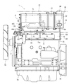
Classifications
-
- F—MECHANICAL ENGINEERING; LIGHTING; HEATING; WEAPONS; BLASTING
- F01—MACHINES OR ENGINES IN GENERAL; ENGINE PLANTS IN GENERAL; STEAM ENGINES
- F01N—GAS-FLOW SILENCERS OR EXHAUST APPARATUS FOR MACHINES OR ENGINES IN GENERAL; GAS-FLOW SILENCERS OR EXHAUST APPARATUS FOR INTERNAL-COMBUSTION ENGINES
- F01N3/00—Exhaust or silencing apparatus having means for purifying, rendering innocuous, or otherwise treating exhaust
- F01N3/02—Exhaust or silencing apparatus having means for purifying, rendering innocuous, or otherwise treating exhaust for cooling, or for removing solid constituents of, exhaust
- F01N3/021—Exhaust or silencing apparatus having means for purifying, rendering innocuous, or otherwise treating exhaust for cooling, or for removing solid constituents of, exhaust by means of filters
- F01N3/033—Exhaust or silencing apparatus having means for purifying, rendering innocuous, or otherwise treating exhaust for cooling, or for removing solid constituents of, exhaust by means of filters in combination with other devices
- F01N3/0335—Exhaust or silencing apparatus having means for purifying, rendering innocuous, or otherwise treating exhaust for cooling, or for removing solid constituents of, exhaust by means of filters in combination with other devices with exhaust silencers in a single housing
-
- F—MECHANICAL ENGINEERING; LIGHTING; HEATING; WEAPONS; BLASTING
- F01—MACHINES OR ENGINES IN GENERAL; ENGINE PLANTS IN GENERAL; STEAM ENGINES
- F01N—GAS-FLOW SILENCERS OR EXHAUST APPARATUS FOR MACHINES OR ENGINES IN GENERAL; GAS-FLOW SILENCERS OR EXHAUST APPARATUS FOR INTERNAL-COMBUSTION ENGINES
- F01N13/00—Exhaust or silencing apparatus characterised by constructional features
- F01N13/009—Exhaust or silencing apparatus characterised by constructional features having two or more separate purifying devices arranged in series
- F01N13/0093—Exhaust or silencing apparatus characterised by constructional features having two or more separate purifying devices arranged in series the purifying devices are of the same type
-
- F—MECHANICAL ENGINEERING; LIGHTING; HEATING; WEAPONS; BLASTING
- F01—MACHINES OR ENGINES IN GENERAL; ENGINE PLANTS IN GENERAL; STEAM ENGINES
- F01N—GAS-FLOW SILENCERS OR EXHAUST APPARATUS FOR MACHINES OR ENGINES IN GENERAL; GAS-FLOW SILENCERS OR EXHAUST APPARATUS FOR INTERNAL-COMBUSTION ENGINES
- F01N13/00—Exhaust or silencing apparatus characterised by constructional features
- F01N13/009—Exhaust or silencing apparatus characterised by constructional features having two or more separate purifying devices arranged in series
- F01N13/0097—Exhaust or silencing apparatus characterised by constructional features having two or more separate purifying devices arranged in series the purifying devices are arranged in a single housing
-
- F—MECHANICAL ENGINEERING; LIGHTING; HEATING; WEAPONS; BLASTING
- F01—MACHINES OR ENGINES IN GENERAL; ENGINE PLANTS IN GENERAL; STEAM ENGINES
- F01N—GAS-FLOW SILENCERS OR EXHAUST APPARATUS FOR MACHINES OR ENGINES IN GENERAL; GAS-FLOW SILENCERS OR EXHAUST APPARATUS FOR INTERNAL-COMBUSTION ENGINES
- F01N13/00—Exhaust or silencing apparatus characterised by constructional features
- F01N13/18—Construction facilitating manufacture, assembly, or disassembly
- F01N13/1805—Fixing exhaust manifolds, exhaust pipes or pipe sections to each other, to engine or to vehicle body
-
- F—MECHANICAL ENGINEERING; LIGHTING; HEATING; WEAPONS; BLASTING
- F01—MACHINES OR ENGINES IN GENERAL; ENGINE PLANTS IN GENERAL; STEAM ENGINES
- F01N—GAS-FLOW SILENCERS OR EXHAUST APPARATUS FOR MACHINES OR ENGINES IN GENERAL; GAS-FLOW SILENCERS OR EXHAUST APPARATUS FOR INTERNAL-COMBUSTION ENGINES
- F01N13/00—Exhaust or silencing apparatus characterised by constructional features
- F01N13/18—Construction facilitating manufacture, assembly, or disassembly
- F01N13/1838—Construction facilitating manufacture, assembly, or disassembly characterised by the type of connection between parts of exhaust or silencing apparatus, e.g. between housing and tubes, between tubes and baffles
- F01N13/1844—Mechanical joints
- F01N13/1855—Mechanical joints the connection being realised by using bolts, screws, rivets or the like
-
- F—MECHANICAL ENGINEERING; LIGHTING; HEATING; WEAPONS; BLASTING
- F01—MACHINES OR ENGINES IN GENERAL; ENGINE PLANTS IN GENERAL; STEAM ENGINES
- F01N—GAS-FLOW SILENCERS OR EXHAUST APPARATUS FOR MACHINES OR ENGINES IN GENERAL; GAS-FLOW SILENCERS OR EXHAUST APPARATUS FOR INTERNAL-COMBUSTION ENGINES
- F01N13/00—Exhaust or silencing apparatus characterised by constructional features
- F01N13/18—Construction facilitating manufacture, assembly, or disassembly
- F01N13/1888—Construction facilitating manufacture, assembly, or disassembly the housing of the assembly consisting of two or more parts, e.g. two half-shells
- F01N13/1894—Construction facilitating manufacture, assembly, or disassembly the housing of the assembly consisting of two or more parts, e.g. two half-shells the parts being assembled in longitudinal direction
-
- F—MECHANICAL ENGINEERING; LIGHTING; HEATING; WEAPONS; BLASTING
- F01—MACHINES OR ENGINES IN GENERAL; ENGINE PLANTS IN GENERAL; STEAM ENGINES
- F01N—GAS-FLOW SILENCERS OR EXHAUST APPARATUS FOR MACHINES OR ENGINES IN GENERAL; GAS-FLOW SILENCERS OR EXHAUST APPARATUS FOR INTERNAL-COMBUSTION ENGINES
- F01N3/00—Exhaust or silencing apparatus having means for purifying, rendering innocuous, or otherwise treating exhaust
- F01N3/02—Exhaust or silencing apparatus having means for purifying, rendering innocuous, or otherwise treating exhaust for cooling, or for removing solid constituents of, exhaust
- F01N3/021—Exhaust or silencing apparatus having means for purifying, rendering innocuous, or otherwise treating exhaust for cooling, or for removing solid constituents of, exhaust by means of filters
- F01N3/0211—Arrangements for mounting filtering elements in housing, e.g. with means for compensating thermal expansion or vibration
-
- F—MECHANICAL ENGINEERING; LIGHTING; HEATING; WEAPONS; BLASTING
- F01—MACHINES OR ENGINES IN GENERAL; ENGINE PLANTS IN GENERAL; STEAM ENGINES
- F01N—GAS-FLOW SILENCERS OR EXHAUST APPARATUS FOR MACHINES OR ENGINES IN GENERAL; GAS-FLOW SILENCERS OR EXHAUST APPARATUS FOR INTERNAL-COMBUSTION ENGINES
- F01N2470/00—Structure or shape of exhaust gas passages, pipes or tubes
- F01N2470/02—Tubes being perforated
-
- F—MECHANICAL ENGINEERING; LIGHTING; HEATING; WEAPONS; BLASTING
- F01—MACHINES OR ENGINES IN GENERAL; ENGINE PLANTS IN GENERAL; STEAM ENGINES
- F01N—GAS-FLOW SILENCERS OR EXHAUST APPARATUS FOR MACHINES OR ENGINES IN GENERAL; GAS-FLOW SILENCERS OR EXHAUST APPARATUS FOR INTERNAL-COMBUSTION ENGINES
- F01N2470/00—Structure or shape of exhaust gas passages, pipes or tubes
- F01N2470/08—Exhaust gas passages being formed between the walls of an outer shell and an inner chamber
-
- F—MECHANICAL ENGINEERING; LIGHTING; HEATING; WEAPONS; BLASTING
- F01—MACHINES OR ENGINES IN GENERAL; ENGINE PLANTS IN GENERAL; STEAM ENGINES
- F01N—GAS-FLOW SILENCERS OR EXHAUST APPARATUS FOR MACHINES OR ENGINES IN GENERAL; GAS-FLOW SILENCERS OR EXHAUST APPARATUS FOR INTERNAL-COMBUSTION ENGINES
- F01N2470/00—Structure or shape of exhaust gas passages, pipes or tubes
- F01N2470/18—Structure or shape of exhaust gas passages, pipes or tubes the axis of inlet or outlet tubes being other than the longitudinal axis of apparatus
-
- F—MECHANICAL ENGINEERING; LIGHTING; HEATING; WEAPONS; BLASTING
- F01—MACHINES OR ENGINES IN GENERAL; ENGINE PLANTS IN GENERAL; STEAM ENGINES
- F01N—GAS-FLOW SILENCERS OR EXHAUST APPARATUS FOR MACHINES OR ENGINES IN GENERAL; GAS-FLOW SILENCERS OR EXHAUST APPARATUS FOR INTERNAL-COMBUSTION ENGINES
- F01N2590/00—Exhaust or silencing apparatus adapted to particular use, e.g. for military applications, airplanes, submarines
- F01N2590/08—Exhaust or silencing apparatus adapted to particular use, e.g. for military applications, airplanes, submarines for heavy duty applications, e.g. trucks, buses, tractors, locomotives
-
- Y—GENERAL TAGGING OF NEW TECHNOLOGICAL DEVELOPMENTS; GENERAL TAGGING OF CROSS-SECTIONAL TECHNOLOGIES SPANNING OVER SEVERAL SECTIONS OF THE IPC; TECHNICAL SUBJECTS COVERED BY FORMER USPC CROSS-REFERENCE ART COLLECTIONS [XRACs] AND DIGESTS
- Y02—TECHNOLOGIES OR APPLICATIONS FOR MITIGATION OR ADAPTATION AGAINST CLIMATE CHANGE
- Y02T—CLIMATE CHANGE MITIGATION TECHNOLOGIES RELATED TO TRANSPORTATION
- Y02T10/00—Road transport of goods or passengers
- Y02T10/10—Internal combustion engine [ICE] based vehicles
- Y02T10/12—Improving ICE efficiencies
Definitions
- the present invention relates to an exhaust gas purification device mounted on a diesel engine or the like, and more specifically, exhaust gas that removes particulate matter (soot, particulates), NOx (nitrogen oxide), or the like contained in the exhaust gas.
- the present invention relates to a gas purification device.
- a diesel particulate filter or NOx catalyst or the like is provided as an exhaust gas purification device (post-treatment device) in the exhaust path of the diesel engine, and exhaust gas discharged from the diesel engine is supplied to a diesel particulate filter (
- a technology for purifying with a NOx catalyst or the like is known (see Patent Document 1, Patent Document 2, and Patent Document 3).
- Patent Document 4 a technique in which a filter case (inner case) is provided in a casing (outer case) and a particulate filter is disposed in the filter case is also known (see Patent Document 4).
- JP 2000-145430 A Japanese Patent Laid-Open No. 2003-27922 JP 2008-82201 A JP 2001-173429 A
- the diesel engine is versatile and is used in various fields such as agricultural machines, construction machinery, and ships.
- the installation space for diesel engines varies depending on the machine on which they are installed, but in recent years, there are many restrictions (narrow) on the installation space due to demands for weight reduction and compactness.
- the temperature of the exhaust gas passing through it is high (for example, 300 ° C. or higher). For this reason, there is a demand for attaching an exhaust gas purification device to a diesel engine.
- the mounting direction of the exhaust gas purification device can be changed.
- the diesel engine manufactures the cylinder head, cylinder block, crankcase, intake manifold, exhaust manifold, etc., which form the outer shape, using a mold
- the mounting direction of the exhaust gas purification device is changed in the conventional configuration. When doing so, it is necessary to change the design of the mold. Such a design change has a problem that the manufacturing cost increases.
- an object of the present invention is to provide an exhaust gas purification device that solves the above-mentioned problems.
- the invention of claim 1 includes a gas purification filter for purifying exhaust gas from an engine, an inner case incorporating the gas purification filter, and an outer case incorporating the inner case.
- An exhaust gas purifying device comprising an exhaust gas inlet pipe having an exhaust gas inlet, wherein an exhaust gas inlet is provided on one end side in the longitudinal direction of the outer case, and is provided in the middle in the longitudinal direction of the outer case.
- the exhaust gas inlet pipe is arranged, and the exhaust gas outlet of the exhaust gas inlet pipe is connected to the exhaust gas inlet.
- the exhaust gas inlet side of the exhaust gas inlet pipe is connected to the exhaust manifold of the engine so that the mounting direction can be changed. is there.
- the exhaust gas inlet pipe covers the exhaust gas inlet and extends in a longitudinal direction of the outer case in the outer case. It is attached.
- an exhaust gas introduction passage is constituted by the outer side surface of the outer case and the inner side surface of the exhaust gas inlet pipe. is there.
- the exhaust gas inlet side of the exhaust gas inlet pipe is located at a longitudinal center portion of the outer case, and the outer case is The engine is located between a cooling fan on one side of the engine and a flywheel housing on the other side.
- a plurality of filter supports are attached to the cylinder head of the engine, and one end in the longitudinal direction and the other end in the longitudinal direction of the outer case.
- the side is detachably connected to the cylinder head via each filter support.
- an exhaust gas purification device comprising a gas purification filter for purifying exhaust gas from an engine, an inner case incorporating the gas purification filter, and an outer case incorporating the inner case.
- the exhaust gas inlet pipe has an exhaust gas inlet, and the exhaust gas inlet is provided at one end side in the longitudinal direction of the outer case, so that the length in the longitudinal direction of the outer case is effectively used.
- the gas purification filter can be formed long, or the exhaust gas flow distance in the outer case can be set long, so that the exhaust gas purification performance of the exhaust gas purification device can be improved.
- the exhaust gas inlet pipe is disposed in the middle in the longitudinal direction of the outer case, and the exhaust gas outlet of the exhaust gas inlet pipe is connected to the exhaust gas inlet, While improving the gas purification performance, there is an effect that the exhaust gas purification device can be stably supported by the exhaust gas inlet pipe in the middle in the longitudinal direction of the outer case.
- the structure of the outer case can be changed without changing the structure of the outer case.
- the direction of the exhaust gas outlet from the outer case can be selected and changed. That is, a plurality of specifications in which the directions of the exhaust gas outlets are different can be dealt with by a single type of exhaust gas purification device. Therefore, since the configuration of the exhaust gas purification device itself does not change, there is no possibility that the tendency of exhaust emissions (particulate matter, NOx, etc.) in the exhaust gas passing through the exhaust gas purification device will change, and the engine is mounted. There is an effect that it is possible to save time and labor for carrying out a test check and a shipping application for each work machine, and to suppress the manufacturing cost.
- the exhaust gas inlet pipe is attached to the outer case so as to cover the exhaust gas inlet and extend in the longitudinal direction of the outer case. It itself functions as a reinforcing member for the outer case. Therefore, without providing a dedicated reinforcing member, the rigidity of the outer case can be improved and the weight can be reduced. In addition, since the number of components can be reduced compared to a structure in which a dedicated reinforcing member is provided, it can be configured at low cost.
- the exhaust gas introduction passage is constituted by the outer side surface of the outer case and the inner side surface of the exhaust gas inlet pipe, the inside of the exhaust gas inlet pipe (in the introduction passage)
- the outer case can be heated with the exhaust gas, and a decrease in the temperature of the exhaust gas passing through the exhaust gas purification device can be suppressed. Therefore, there is an advantage that the exhaust gas purification performance of the exhaust gas purification device can be improved.
- the invention of claim 5 further embodies the invention of claim 1.
- the exhaust gas inlet side of the exhaust gas inlet pipe is located at the longitudinal center of the outer case, and the outer case is a cooling fan on one side of the engine and a fly on the other side. Since it is located between the wheel housing, for example, an exhaust gas outlet from the outer case is arranged on the cooling fan side, and an exhaust gas outlet from the outer case is on the flywheel housing side. There is an effect that it is possible to cope with the specifications to be arranged with the configuration of one type of exhaust gas purification device.
- a plurality of filter supports are attached to the cylinder head of the engine, and one end in the longitudinal direction and the other end in the longitudinal direction of the outer case are interposed via the filter supports. Therefore, the exhaust gas purifying device can be arranged with high rigidity in the engine as one of the components of the engine. There is an effect that the versatility of the engine can be improved.
- the exhaust gas purification device can be supported with high rigidity by using the cylinder head, which is a highly rigid component of the engine, and damage to the exhaust gas purification device due to vibration or the like can be prevented.
- the exhaust gas purification device can be shipped in the engine at the production site of the engine, and there is an advantage that the engine and the exhaust gas purification device can be configured in a compact manner.
- FIG. 1 is a front cross-sectional view of an exhaust gas purification device according to an embodiment of the present invention. It is the same external appearance bottom view. It is the left view seen from the exhaust gas inflow side. It is right side sectional drawing seen from the exhaust gas discharge side.
- FIG. 2 is an exploded front sectional view of FIG. 1. It is a front view expanded sectional view of the exhaust gas discharge side. It is a side view enlarged sectional view on the same exhaust gas discharge side. It is an enlarged bottom view of the same exhaust gas inflow side. It is an enlarged sectional view in plan view of the exhaust gas inflow side. It is an expanded sectional view of an inner side case support body. It is an expanded sectional view of the inner side case support body which shows the modification of FIG.
- FIG. 16 is a left side view of the exhaust gas purification device when the direction of attachment is reversed 180 ° from the state of FIG. 15.
- the exhaust gas inlet 12 side of the diesel particulate filter 1 is the left side
- the silencer 30 side is the right side.
- a continuously regenerating diesel particulate filter 1 (hereinafter referred to as DPF) is provided as an exhaust gas purifying apparatus of the present embodiment.
- the DPF 1 is for physically collecting particulate matter (PM) and the like in the exhaust gas.
- the DPF 1 exhausts a diesel oxidation catalyst 2 such as platinum that generates nitrogen dioxide (NO2) and a soot filter 3 having a honeycomb structure that continuously oxidizes and removes the collected particulate matter (PM) at a relatively low temperature.
- the gas is arranged in series in the gas movement direction (from left to right in FIG. 1).
- the DPF 1 is configured so that the soot filter 3 is continuously regenerated.
- the DPF 1 can reduce carbon monoxide (CO) and hydrocarbons (HC) in the exhaust gas in addition to the removal of particulate matter (PM) in the exhaust gas.
- a diesel oxidation catalyst 2 as a gas purification filter for purifying exhaust gas discharged from an engine is installed in a substantially cylindrical catalyst inner case 4 made of a heat-resistant metal material.
- the catalyst inner case 4 is provided in a substantially cylindrical catalyst outer case 5 made of a heat-resistant metal material. That is, the catalyst inner case 4 is fitted on the outside of the diesel oxidation catalyst 2 via the mat-shaped ceramic fiber catalyst heat insulating material 6. Further, the catalyst outer case 5 is fitted on the outer side of the catalyst inner case 4 via a thin plate support 7 having an I-shaped end face. Note that the diesel oxidation catalyst 2 is protected by the catalyst heat insulating material 6. The stress (deformation force) of the catalyst outer case 5 transmitted to the catalyst inner case 4 is reduced by the thin plate support 7.
- a disc-shaped left lid 8 is fixed to the left ends of the catalyst inner case 4 and the catalyst outer case 5 by welding.
- a sensor connection plug 10 is fixed to the left lid body 8 through a seat plate body 9.
- the left end face 2a of the diesel oxidation catalyst 2 and the left lid 8 are opposed to each other with a predetermined distance L1 for gas inflow space.
- An exhaust gas inflow space 11 is formed between the left end face 2 a of the diesel oxidation catalyst 2 and the left lid 8.
- the sensor connection plug 10 is connected to an unillustrated inlet side exhaust gas pressure sensor, an inlet side exhaust gas temperature sensor, and the like.
- an exhaust gas inlet 12 is opened at one end in the longitudinal direction of the catalyst inner case 4 and the catalyst outer case 5.
- the exhaust gas inlet 12 of the embodiment has an elliptical shape formed at the left end portions of the catalyst inner case 4 and the catalyst outer case 5.
- the elliptical exhaust gas inlet 12 has a short diameter in the exhaust gas movement direction (center line direction of the cases 4 and 5) and a direction orthogonal to the exhaust gas movement direction (circumferential direction of the cases 4 and 5). It has a long diameter.
- a closing ring body 15 is fixed between the opening edge 13 of the catalyst inner case 4 and the opening edge 14 of the catalyst outer case 5 in a sandwiched manner. A gap between the opening edge 13 of the catalyst inner case 4 and the opening edge 14 of the catalyst outer case 5 is closed by the closing ring body 15.
- An exhaust ring 15 prevents the exhaust gas from flowing between the catalyst inner case 4 and the catalyst outer case 5.
- an exhaust gas inlet pipe 16 is disposed on the outer surface of the catalyst outer case 5 in which the exhaust gas inlet 12 is formed.
- the exhaust gas inlet pipe 16 is formed in a half-cylinder shape that opens upward, and a rectangular upward opening end portion 16b on the large diameter side covers the exhaust gas inlet 12 and the length of the catalyst outer case 5 ( It is welded and fixed to the outer surface of the catalyst outer case 5 so as to extend in the (left and right) direction. Therefore, the upward opening end portion 16 b on the exhaust gas outlet side of the exhaust gas inlet pipe 16 is connected to the exhaust gas inlet 12 of the catalyst outer case 5.
- the exhaust gas inlet pipe 16 is provided with a small-diameter perfect circular downward opening end portion 16a at the right end portion corresponding to the middle portion in the longitudinal direction of the catalyst outer case 5 as the exhaust gas inlet side, and the downward opening end portion 16a.
- the exhaust connection flange body 17 is fixed by welding to the outer peripheral portion of the.
- the exhaust connection flange body 17 is detachably fastened to an exhaust manifold 71 of a diesel engine 70 described later via bolts 18.
- the exhaust connection flange body 17 can be fastened to the exhaust manifold 71 with the bolt 18 even in the state where the left and right mounting directions of the DPF 1 are turned upside down (reversed left and right).
- the positional relationship of the insertion hole of 17 and the exhaust manifold 71 is set. That is, the downward opening end portion 16a of the exhaust gas inlet pipe 16 is connected to the exhaust manifold 71 so that the mounting direction can be changed.
- the downward opening end portion 16a of the exhaust gas inlet pipe 16 in the embodiment is located at a substantially central portion in the longitudinal (left and right) direction of the DPF 1 (outer cases 5, 21, 32). For this reason, the length of the DPF 1 in the exhaust gas movement direction (left-right direction) has a dimension that is substantially equally divided across the downward opening end portion 16a of the exhaust gas inlet pipe 16.
- the left end portion side of the exhaust gas inlet pipe 16 covers the exhaust gas inlet port 12 of the catalyst outer case 5, and the right end portion of the exhaust gas inlet pipe 16 is connected to the exhaust gas inlet side.
- a downward opening end portion 16a is formed. That is, the downward opening end portion 16a of the exhaust gas inlet pipe 16 is offset to the exhaust gas movement downstream side (right side of the catalyst outer case 5) with respect to the elliptical exhaust gas inlet 12 (shifted). Is provided.
- the upward opening end portion 16 b of the exhaust gas inlet pipe 16 is welded and fixed to the outer surface of the catalyst outer case 5 so as to cover the exhaust gas inlet 12 and extend in the longitudinal (left and right) direction of the catalyst outer case 5. Therefore, the exhaust gas introduction passage 60 is configured by the outer surface of the catalyst outer case 5 and the inner surface of the exhaust gas inlet pipe 16.
- the exhaust gas of the engine 70 enters the exhaust gas inlet pipe 16 from the exhaust manifold 71, enters the exhaust gas inflow space 11 from the exhaust gas inlet pipe 16 through the exhaust gas inlet 12, and the diesel oxidation catalyst 2. From the left end face 2a. Nitrogen dioxide (NO 2) is generated by the oxidation action of the diesel oxidation catalyst 2.
- NO 2 Nitrogen dioxide
- the soot filter 3 as a gas purification filter for purifying exhaust gas discharged from the engine 70 is provided in a substantially cylindrical filter inner case 20 made of a heat-resistant metal material.
- the inner case 4 is provided in a substantially cylindrical filter outer case 21 made of a heat-resistant metal material. That is, the filter inner case 20 is fitted on the outside of the soot filter 3 via the mat-shaped ceramic fiber filter heat insulating material 22. The soot filter 3 is protected by the filter heat insulating material 22.
- the catalyst side flange 25 is welded to the end of the catalyst outer case 5 on the downstream side (right side) of the exhaust gas movement.
- the filter-side flange 26 is welded to the middle of the filter inner case 20 in the exhaust gas movement direction and the end of the filter outer case 21 on the upstream side (left side) of the exhaust gas movement.
- the catalyst side flange 25 and the filter side flange 26 are detachably fastened by bolts 27 and nuts 28.
- the diameter of the cylindrical catalyst inner case 4 and the diameter of the cylindrical filter inner case 20 are substantially the same. Further, the diameter of the cylindrical catalyst outer case 5 and the diameter of the cylindrical filter outer case 21 are substantially the same.
- the exhaust gas movement downstream side (right side) end of the catalyst inner case 4 is shown in a state where the filter outer case 21 is connected to the catalyst outer case 5 via the catalyst side flange 25 and the filter side flange 26, the exhaust gas movement downstream side (right side) end of the catalyst inner case 4 is shown.
- the end portion on the upstream side (left side) of the exhaust gas movement of the filter inner case 20 faces the portion spaced apart by a fixed interval L2 for sensor attachment.
- the sensor mounting space 29 is formed between the exhaust gas movement downstream side (right side) end of the catalyst inner case 4 and the exhaust gas movement upstream side (left side) end of the filter inner case 20.
- a sensor connection plug 50 is fixed to the catalyst outer case 5 at the sensor mounting space 29 position.
- the sensor connection plug 50 is connected to a filter inlet side exhaust gas pressure sensor (not shown), a filter inlet side exhaust gas temperature sensor (thermistor), and the like.
- the cylindrical length L4 of the catalyst outer case 5 in the exhaust gas movement direction is longer than the cylindrical length L3 of the catalyst inner case 4 in the exhaust gas movement direction.
- the cylindrical length L6 of the filter outer case 21 in the exhaust gas movement direction is shorter than the cylindrical length L5 of the filter inner case 20 in the exhaust gas movement direction.
- a length (L2 + L3 + L5) obtained by adding the constant interval L2 of the sensor mounting space 29, the cylindrical length L3 of the catalyst inner case 4 and the cylindrical length L5 of the filter inner case 20 is the cylindrical length L4 of the catalyst outer case 5.
- nitrogen dioxide (NO2) generated by the oxidation action of the diesel oxidation catalyst 2 is supplied to the soot filter 3 from the left end face 3a.
- the collected particulate matter (PM) in the exhaust gas of the diesel engine 70 collected by the soot filter 3 is continuously oxidized and removed at a relatively low temperature by nitrogen dioxide (NO2).
- nitrogen dioxide (NO2) generated by the oxidation action of the diesel oxidation catalyst 2
- the collected particulate matter (PM) in the exhaust gas of the diesel engine 70 collected by the soot filter 3 is continuously oxidized and removed at a relatively low temperature by nitrogen dioxide (NO2).
- carbon monoxide (CO) and hydrocarbons (HC) in the exhaust gas of the diesel engine 70 are reduced.
- a diesel oxidation catalyst 2 or soot filter 3 as a gas purification filter for purifying exhaust gas discharged from a diesel engine 70, and a catalyst inner case in which the diesel oxidation catalyst 2 or soot filter 3 is installed.
- a filter inner case 20 a catalyst outer case 5 in which the catalyst inner case 4 and the filter inner case 20 are installed, and a filter outer case 21, a plurality of sets of diesel oxidation catalysts 2 and soot
- the filter 3, the catalyst inner case 4, the filter inner case 20, the catalyst outer case 5, and the filter outer case 21 are provided, and the catalyst outer case 5 and the filter outer case 21 with respect to the connection boundary position of the diesel oxidation catalyst 2 and the soot filter 3.
- a gas sensor or the like can be easily arranged at the connection boundary position of the diesel oxidation catalyst 2 and the soot filter 3. Since the length of the catalyst outer case 5 and the filter outer case 21 in the exhaust gas movement direction can be shortened, the rigidity and weight reduction of the catalyst outer case 5 and the filter outer case 21 can be achieved.
- FIGS. 1 to 5 two types of diesel oxidation catalysts 2 and soot filters 3 are provided, and a filter inner case 20 in which one soot filter 3 is installed is provided in the catalyst of the other diesel oxidation catalyst 2. Since the catalyst outer case 5 in which the inner case 4 is installed is configured to overlap, the catalyst outer case 5 or the soot filter 3 is secured while maintaining the length of the diesel oxidation catalyst 2 or the soot filter 3 in the exhaust gas movement direction. The length of the filter outer case 21 in the exhaust gas movement direction can be shortened.
- the catalyst inner case 4 (the other diesel oxidation catalyst 2) where the catalyst outer case 5 overlaps is largely exposed to the outside by the separation (disassembly) of the catalyst outer case 5 and the filter outer case 21, the catalyst inner case 4 is exposed.
- the exposure range of the case 4 (the other diesel oxidation catalyst 2) is increased, and maintenance work such as soot removal of the one soot filter 3 can be easily performed.
- a diesel oxidation catalyst 2 and a soot filter 3 are provided as a plurality of sets of gas purification filters, and the catalyst side flange 25 and the filter side flange 26 are offset on the outer peripheral side of the soot filter 3. Therefore, by separating the catalyst outer case 5 and the filter outer case 21, the end of the inner case 20 on the exhaust gas inlet side of the soot filter 5 can be greatly exposed from the end surface of the outer case 21. Maintenance work such as removal of soot adhering to the case 20 can be easily performed.
- FIGS. 1 to 5 two types of diesel oxidation catalyst 2 and soot filter 3 are provided, and a catalyst inner case 4 in which one diesel oxidation catalyst 2 is installed, and the other soot filter 3 in the interior. Since the sensor mounting space 29 is formed between the filter inner case 20 and the filter outer case 20 to be provided, the connection length of the catalyst outer case 5 and the filter outer case 21 in the exhaust gas moving direction is shortened, and the catalyst outer case 5 is reduced. In addition, a gas sensor or the like can be easily arranged in the sensor mounting space 29 at the connection boundary position between the diesel oxidation catalyst 2 and the soot filter 3 while improving the rigidity and weight of the filter outer case 21 and the like.
- a sensor connection plug 50 as a sensor support is assembled to the catalyst outer case 5 that overlaps the filter inner case 20, and the sensor is installed at the connection boundary position of the diesel oxidation catalyst 2 and the soot filter 3. Since a gas sensor such as a filter inlet side exhaust gas pressure sensor or a filter inlet side exhaust gas temperature sensor (thermistor) (not shown) is arranged through the connection plug 50, the catalyst outer case 5 and the filter outer case are arranged.
- the sensor connection plug 50 can be compactly installed at the connection boundary position between the diesel oxidation catalyst 2 and the soot filter 3 while improving the rigidity and weight of the engine 21 and the like.
- the diesel oxidation catalyst 2 and the soot filter 3 are provided as gas purification filters for purifying the exhaust gas discharged from the engine.
- urea reducing agent
- NOx selective reduction catalyst NOx removal catalyst
- NH3 ammonia
- NOx removal catalyst a NOx selective reduction catalyst
- ammonia removal catalyst is provided in the filter inner case 20 as a gas purification filter
- nitrogen oxidation in the exhaust gas exhausted by the engine is performed.
- the substance (NOx) is reduced and can be discharged as harmless nitrogen gas (N2).
- a diesel oxidation catalyst 2 or soot filter 3 as a gas purification filter for purifying exhaust gas discharged from a diesel engine 70, and a catalyst inner case in which the diesel oxidation catalyst 2 or soot filter 3 is installed.
- a filter inner case 20, and a catalyst outer case 5 and a filter outer case 21 in which the catalyst inner case 4 and the filter inner case 20 are installed. are connected to the catalyst outer case 5 and the filter outer case 21, and an exhaust gas inlet pipe 16 as an inlet component to which external stress is applied is arranged in the catalyst outer case 5.
- the double structure of the catalyst inner case 4 or the filter inner case 20 and the catalyst outer case 5 or the filter outer case 21 improves the heat insulating properties of the diesel oxidation catalyst 2 or the soot filter 3, thereby treating the diesel oxidation catalyst 2 or the soot filter 3.
- a plurality of sets of diesel oxidation catalysts 2 and soot filters 3, a catalyst inner case 4 and a filter inner case 20, and a catalyst outer case 5 and a filter outer case 21 are provided.
- the case 5 and the filter outer case 21 are connected by a catalyst side flange 25 and a filter side flange 26 as flange bodies. Accordingly, in consideration of the configuration of the exhaust gas inlet pipe 16 and the movement of exhaust gas between the plurality of sets of diesel oxidation catalyst 2 and the soot filter 3, a plurality of sets of catalyst inner cases 4, filter inner cases 20, and a plurality of sets of The catalyst outer case 5 and the filter outer case 21 can be configured functionally.
- the processing capacity, regeneration capacity, etc. of a plurality of sets of diesel oxidation catalysts 2 and soot filters 3 can be easily improved.
- the length of the catalyst inner case 4 and the filter inner case 20 in the exhaust gas moving direction is different from the length of the catalyst outer case 5 and the filter outer case 21 in the exhaust gas moving direction. Yes. Therefore, the flange body connecting the catalyst outer case 5 and the filter outer case 21 can be offset with respect to the joining position of the plurality of sets of the diesel oxidation catalyst 2 and the soot filter 3.
- the mounting interval of the plurality of sets of diesel oxidation catalysts 2 and soot filters 3 can be easily reduced or expanded.
- a plurality of sets of diesel oxidation catalysts 2 and soot filters 3, a catalyst inner case 4 and a filter inner case 20, a catalyst outer case 5 and a filter outer case 21 are provided.
- the soot filter 3 is configured such that the catalyst side flange 25 and the filter side flange 26 connecting the plurality of sets of the catalyst outer case 5 and the filter outer case 21 are offset with respect to the joining position of the catalyst 2 and the soot filter 3.
- a catalyst outer case 5 facing the other diesel oxidation catalyst 2 is configured to overlap with the filter inner case 20 facing the other.
- a sensor or the like can be easily arranged between the junctions of the plurality of sets of diesel oxidation catalysts 2 and the soot filter 3 while the junction interval of the plurality of sets of diesel oxidation catalysts 2 and the soot filter 3 can be reduced.
- the lengths of the plurality of sets of catalyst outer cases 5 and filter outer cases 21 in the exhaust gas movement direction can be shortened to improve the rigidity and weight of the plurality of sets of catalyst outer cases 5 and filter outer cases 21 and the like. .
- the length of the plurality of sets of catalyst outer case 5 and filter outer case 21 in the exhaust gas moving direction can be shortened.
- the silencer 30 for attenuating the exhaust gas sound discharged from the diesel engine 70 includes a substantially cylindrical silencer inner case 31 made of a heat resistant metal material, and an abbreviation made of a heat resistant metal material. It has a cylindrical silencing outer case 32 and a disc-shaped right lid 33 fixed to the right end of the silencing inner case 31 and the silencing outer case 32 by welding.
- a silencer inner case 31 is provided in the silencer outer case 32.
- the diameter size of the cylindrical catalyst inner case 4, the diameter size of the cylindrical filter inner case 20, and the cylindrical sound deadening inner case 31 are substantially the same size. Further, the diameter of the cylindrical catalyst outer case 5, the diameter of the cylindrical filter outer case 21, and the cylindrical silencing outer case 32 are substantially the same.
- an exhaust gas outlet pipe 34 is passed through the silencer inner case 31 and the silencer outer case 32.
- One end side of the exhaust gas outlet pipe 34 is closed by an outlet lid 35.
- a number of exhaust holes 36 are formed in the entire exhaust gas outlet pipe 34 inside the silencer inner case 31.
- the interior of the muffler inner case 31 is communicated with an exhaust gas outlet pipe 34 via a number of exhaust holes 36.
- a silencer and a tail pipe (not shown) are connected to the other end side of the exhaust gas outlet pipe 34.
- a number of silencing holes 37 are opened in the silencing inner case 31.
- the interior of the silencer inner case 31 is communicated between the silencer inner case 31 and the silencer outer case 32 via a number of silencer holes 37.
- the space between the silencer inner case 31 and the silencer outer case 32 is closed by the right lid 33 and the thin plate support 38.
- a ceramic fiber silencer 39 is filled between the silencer inner case 31 and the silencer outer case 32.
- the exhaust gas movement upstream (left side) end of the muffler inner case 31 is connected to the exhaust gas movement upstream (left side) end of the muffler outer case 32 via a thin plate support 38.
- exhaust gas is discharged from the muffler inner case 31 through the exhaust gas outlet pipe 34. Further, in the silencer inner case 31, exhaust gas sounds (mainly high frequency band sounds) are absorbed into the silencer 39 from the numerous silencer holes 37. The noise of the exhaust gas discharged from the outlet side of the exhaust gas outlet pipe 34 is attenuated.
- exhaust gas sounds mainly high frequency band sounds
- the filter side outlet flange 40 is welded to the exhaust gas movement downstream side (right side) end of the filter inner case 20 and the filter outer case 21.
- the silencer flange 41 is welded to the exhaust gas movement upstream side (left side) of the silencer outer case 32.
- the filter side outlet flange 40 and the silencer side flange 41 are detachably fastened by bolts 42 and nuts 43.
- a sensor connection plug 44 is fixed to the filter inner case 20 and the filter outer case 21.
- the sensor connection plug 44 is connected to an unillustrated outlet side exhaust gas pressure sensor, an outlet side exhaust gas temperature sensor (thermistor) and the like.
- a diesel oxidation catalyst 2 or soot filter 3 as a gas purification filter for purifying exhaust gas discharged from the diesel engine 70, and a diesel oxidation catalyst 2 or soot filter 3 are provided.
- Exhaust gas comprising a catalyst inner case 4 or filter inner case 20 as an inner case to be installed inside, and a catalyst outer case 5 or filter outer case 21 as an outer case in which the catalyst inner case 4 or filter inner case 20 is installed.
- the gas purification apparatus includes a silencer 39 as an exhaust sound attenuator that attenuates the exhaust sound of the exhaust gas discharged from the diesel engine 70, and the silencer at the exhaust gas outlet side end of the catalyst outer case 5 or the filter outer case 21.
- the diesel oxidation catalyst 2 or the soot filter 3 While maintaining the exhaust gas purification function, without changing the structure of the diesel oxidation catalyst 2 or the soot filter 3 can be easily added to mute the exhaust gas.
- an exhaust structure in which a tail pipe is directly connected to the outer case, an exhaust structure that further improves the silencing function of an existing silencer, and the like can be easily configured.
- silencing structure 39 formed by punch holes and a fibrous mat can be easily installed.
- the silencer 30 having the silencer 39 is provided as shown in FIGS. 5 to 7 and the silencer 30 is detachably connected to the exhaust gas outlet side end of the filter outer case 21, By attaching / detaching the silencer 30, the exhaust gas silencing function in the diesel oxidation catalyst 2 or the soot filter 3 can be easily changed.
- a silencer 30 having a silencer 39 is provided, and the catalyst outer case 5 or the filter outer case 21 and the silencer 30 are formed in a cylindrical shape having substantially the same outer diameter, respectively.
- a filter-side outlet flange 40 as a ring-shaped flange body is provided at an end portion of the exhaust gas outlet side of 21, and a silencer 39 is attached to an end portion of the exhaust gas outlet side of the filter outer case 21 via the filter-side outlet flange 40. Since the silencer 30 having substantially the same outer diameter is connected to the filter outer case 21 by the filter-side outlet flange 40, the catalyst outer case is arranged in the exhaust gas moving direction.
- the catalyst outer case 5 or the filter outer case 21 can be assembled in a compact manner simply by lengthening the mounting dimension of the filter outer case 21.
- the catalyst outer case 5 or the filter outer case 21 can be easily installed close to the side surface of the exhaust gas discharge part of the diesel engine 70.
- the gas purification function of the diesel oxidation catalyst 2 or the soot filter 3 is improved, and the countermeasure for reducing the high frequency of the exhaust gas can be easily executed by installing the silencer 39.
- the silencer inner case 31 and the silencer outer case 32 as silencer casings in which the silencer 39 is incorporated, the one end side is closed, and the other end side is communicated with a tail pipe (not shown).
- An exhaust gas outlet pipe 34, and the silencer inner case 31 and the silencer outer case 32 are passed through the exhaust hole 36 forming portion of the exhaust gas outlet pipe 34, and the filter side outlet of the filter outer case 21 is connected to the filter side outlet. Since the silencer inner case 31 and the silencer outer case 32 are detachably connected via the flange 40, the diesel oxidation catalyst 2 or the soot filter can be removed by attaching and detaching the silencer inner case 31 and the silencer outer case 32.
- an exhaust structure in which a tail pipe (not shown) is directly connected to the filter outer case 21 can be easily configured by arranging the silencer inner case 31 and the silencer outer case 32 in which the silencer 39 is not incorporated. Further, as a countermeasure for reducing the high frequency of exhaust gas, which has been difficult to implement at the site of the diesel oxidation catalyst 2 or the soot filter 3, a silencer 39 (punch hole and fibrous mat) is provided in the silencer inner case 31 and the silencer outer case 32. Etc.) The muffler structure can be easily configured.
- the silencer casing has a cylindrical silencer inner case 31 and a cylindrical silencer outer case 32, and the silencer inner case 31 is arranged in the silencer outer case 32, and the silencer inner case is arranged. Since the silencer 39 is filled between the silencer 31 and the silencer outer case 32 and a number of silencer holes 37 are formed in the silencer inner case 31, the catalyst inner case 4 in which the diesel oxidation catalyst 2 or the soot filter 3 is installed.
- the silencer casing (the silencer inner case 31 and the silencer outer case 32) can be configured by approximating an exhaust gas purification structure including the filter inner case 20, the catalyst outer case 5, or the filter outer case 21.
- the silencer casing is silenced by using the same material (pipe or the like) as the catalyst inner case 4 or the filter inner case 20, the catalyst outer case 5 or the filter outer case 21 for installing the diesel oxidation catalyst 2 or the soot filter 3.
- the inner case 31 and the silencer outer case 32 can be formed. The manufacturing cost of the silencer casing can be easily reduced.
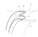
- the inner case support 7 will be described with reference to FIGS. 1, 5, and 10 to 14.
- the cylindrical catalyst outer case 5 is fitted on the outer side of the cylindrical catalyst inner case 4 via a ring-shaped thin plate inner case support 7 having an I-shaped end face.
- the stress (deformation force) of the catalyst outer case 5 is reduced by the thin plate inner case support 7.
- the inner case support 7 includes an I-shaped thin plate portion 7a and an outer case connecting portion 7b. The inner edge of the I-shaped thin plate portion 7a is welded to the outer surface of the catalyst inner case 4 on the downstream side of the exhaust gas movement.
- the I-shaped thin plate portion 7 a is erected substantially vertically on the outer surface of the catalyst inner case 4, and the I-shaped thin plate portion 7 a protrudes radially from the outer surface of the catalyst inner case 4.
- the outer case connecting portion 7b is extended from the outer diameter side edge of the I-shaped thin plate portion 7a in a direction bent substantially at a right angle.
- the cross-sectional end surface of the inner case support 7 is formed in an L shape by the I-shaped thin plate portion 7a and the outer case connecting portion 7b.
- the end of the outer case connecting portion 7b is extended in the exhaust gas moving direction (in the direction of the center line of the cylindrical case 5).
- the outer case connecting portion 7b is welded to the inner surface of the intermediate portion of the catalyst outer case 5 in the exhaust gas movement direction through the welding hole 5a opened in the catalyst outer case 5.
- the welding hole 5a is closed by welding the outer case connecting portion 7b. That is, as shown in FIGS. 1 and 10, the diesel oxidation catalyst 2 or the soot filter 3 as a gas purification filter for purifying the exhaust gas discharged from the diesel engine 70 and the inside in which the diesel oxidation catalyst 2 or the soot filter 3 is installed.
- an exhaust gas purification apparatus comprising a catalyst inner case 4 or a filter inner case 20 as a case, and a catalyst outer case 5 or a filter outer case 21 as an outer case in which the catalyst inner case 4 or the filter inner case 20 is provided.
- a ring-shaped inner case support 7 is provided between the catalyst inner case 4 and the catalyst outer case 5, and the inner case support 7 is formed of a flexible material having a vibration damping function.
- the outer case 5 is configured to support the catalyst inner case 4 via the inner case support 7.
- the vibration of the catalyst outer case 5 is damped by the inner case support 7 and the vibration transmitted from the catalyst outer case 5 to the catalyst inner case 4 can be reduced, the sealing performance of the diesel oxidation catalyst 2 is reduced, and the catalyst outer case 5 is reduced.
- damage or dropout of the catalyst inner case 4 or the diesel oxidation catalyst 2 can be easily prevented. That is, the durability of the diesel oxidation catalyst 2 can be improved by reducing the sealing performance of the catalyst outer case 5 or the catalyst inner case 4.
- the maintenance workability of the soot filter 3 can be easily improved.
- the temperature of the catalyst inner case 4 can be easily managed by the heat insulating action of the space between the catalyst inner case 4 and the catalyst outer case 5.
- the temperature of the diesel oxidation catalyst 2 can be maintained at an appropriate catalyst temperature (about 300 to 500 degrees).
- the inner case support 7 is formed by a thin plate having an I-shaped cross section, and one end of the inner case support 7 is extended in a direction along the inner surface of the catalyst outer case 5.
- the outer case connecting portion 7b to be welded to the catalyst outer case 5 is formed on the extended portion on one end side of the inner case support 7, and the outer case connecting portion 7b is fixed to the inner surface of the catalyst outer case 5. Therefore, with the other end of the inner case support 7 welded to the outer surface of the catalyst inner case 4, the catalyst inner case 4 is inserted into the catalyst outer case 5, and the catalyst is removed from the outside of the catalyst outer case 5.
- the outer case connecting portion 7 b can be welded to the outer case 5.
- the inner case support 7 can be formed by a thin plate having a thickness that is not limited to the welding operation. Assembly workability of the catalyst outer case 5 and the catalyst inner case 4 can be improved.
- a plurality of diesel oxidation catalysts 2 or soot filters 3, a catalyst inner case 4 or a filter inner case 20, and a catalyst outer case 5 or a filter outer case 21 are provided, and a plurality of diesel engines are provided.
- One soot is configured so that the catalyst side flange 25 or the filter side flange 26 as a flange body connecting the catalyst outer case 5 or the filter outer case 21 is offset with respect to the joining position of the oxidation catalyst 2 or the soot filter 3. Since the catalyst inner case 20 facing the filter 3 is configured to overlap the catalyst outer case 5 facing the other diesel oxidation catalyst 2, the exhaust of the plurality of diesel oxidation catalysts 2 or the soot filters 3 is configured.
- the plurality of catalyst outer casings. 5 or can be shortened exhaust gas moving direction of the length of the filter outer case 21 can be improved and weight reduction of the rigidity of such a plurality of catalyst outer case 5 or the filter outer case 21.
- the filter inner case 20 (the soot filter 3 on the exhaust gas moving downstream side) where the catalyst outer case 5 overlaps can be largely exposed to the outside by the separation (disassembly) of the catalyst outer case 5 or the filter outer case 21. That is, the exposure range of the exhaust gas movement upstream end portion (the filter inner case 20 on the exhaust gas movement downstream side) of the soot filter 3 arranged on the exhaust gas movement downstream side of the plurality of diesel oxidation catalysts 2 or the soot filters 3 is set. Maintenance work such as soot removal of the soot filter 3 on the downstream side of the exhaust gas movement can be easily performed.
- the inner case support 7 is formed by a ring-shaped thin plate having an I-shaped end surface.
- the inner case support 7 is formed by a ring-shaped thin plate having an U-shaped end surface. May be.
- the inner case support 7 may be formed of a ring-shaped thin plate having an S-shaped end face.
- the inner case support 7 may be formed of a ring-shaped thin plate having an end face Z-shape.
- the inner case support 7 may be formed of a ring-shaped thin plate having a composite end face combining a Z-shape and an S-shape.
- the inner case support 7 has an I-shaped thin plate (see FIG. 10), a U-shaped thin plate (see FIG. 11), or an S-shaped cross-sectional end surface.
- the catalyst inner case 4 is elastically supported by the catalyst outer case 5 via the inner case support 7, which is formed by any one of a thin plate (see FIG. 12) or a thin plate having a cross-sectional end surface (see FIG. 13).
- a plurality of sets of catalyst outer case 5 or filter outer case 21 and catalyst inner case 4 or filter inner case 20 are provided, and a plurality of diesel oxidation catalysts 2 or soot filters 3 are combined.
- the inner side of the catalyst inside the catalyst outer case 5 in the exhaust gas movement direction is disposed inside the catalyst via the inner case support 7.
- the outer surface of the exhaust gas moves downstream end of the over scan 4 can be supported with high rigidity. Maintenance workability of the exhaust gas movement upstream end portion of the soot filter 3 arranged on the downstream side of the exhaust gas movement can be easily improved.
- the sealing performance of the diesel oxidation catalyst 2 or the soot filter 3 is reduced, or the catalyst outer case 5 or the filter outer case 21 or the catalyst inner case 4 or the filter inner case 20 or the diesel oxidation catalyst 2 or the soot filter 3 is damaged or dropped off. Can be easily prevented.
- the inner case support is a thin plate having an I-shaped cross section (see FIG. 10), a thin plate having a U-shaped cross section (see FIG. 11), or a thin plate having an S-shaped cross section (see FIG. 11). 12), or a cross-sectional end face is formed by a thin plate (see FIG. 14) of any two or more of Z-shaped thin plates (see FIG. 13), and the catalyst outer case 5 via the inner case support 7 Therefore, for example, a plurality of sets of the catalyst outer case 5 or the filter outer case 21 and the catalyst inner case 4 or the filter inner case 20 are provided, and a plurality of diesel oxidation catalysts are provided.
- the inner casing is disposed on the inner surface side of the catalyst outer case 5 in the exhaust gas movement direction.
- the scan support 7 it can support the outer surface side of the exhaust gas moves downstream end of the catalyst inner case 4 with high rigidity. Maintenance workability of the exhaust gas movement upstream end portion of the soot filter 3 arranged on the downstream side of the exhaust gas movement can be easily improved.
- the sealing performance of the diesel oxidation catalyst 2 or the soot filter 3 is reduced, or the catalyst outer case 5 or the filter outer case 21 or the catalyst inner case 4 or the filter inner case 20 or the diesel oxidation catalyst 2 or the soot filter 3 is damaged or dropped off. Can be easily prevented.
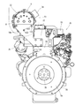
- FIGS. 15 to 18 A structure in which the DPF 1 is provided in the diesel engine 70 will be described with reference to FIGS. 15 to 18 and FIG.
- an exhaust manifold 71 and an intake manifold 73 are arranged on the left and right side surfaces of the cylinder head 72 of the diesel engine 70.
- the cylinder head 72 is mounted on a cylinder block 75 having an engine output shaft 74 (crankshaft) and a piston (not shown).
- the front end and the rear end of the engine output shaft 74 are projected from the front and rear surfaces of the cylinder block 75.
- a cooling fan 76 is provided on the front surface of the cylinder block 75. The rotational force is transmitted from the front end side of the engine output shaft 74 to the cooling fan 76 via the V belt 77.
- a flywheel housing 78 is fixed to the rear surface of the cylinder block 75.
- a flywheel 79 is provided in the flywheel housing 78.
- a flywheel 79 is pivotally supported on the rear end side of the engine output shaft 74.
- the power of the diesel engine 70 is extracted via a flywheel 79 to operating parts such as a backhoe 100 and a forklift 120 described later.
- one end of the first support leg 19a is welded to the silencer outer case 32 by welding.
- the other end side of the first support leg 19a fixed to the silencer outer case 32 is detachable with a bolt 131 on the upper end side of the second support leg 19b attached to the cylinder head 72 near the cooling fan 76. It is concluded to.
- One end side (upper end side) of the third support leg 19c is detachably fastened by a bolt 132 and a nut 133 to the side end surface of the catalyst outer case 5 on the exhaust gas inlet 12 side.
- the other end side (lower end side) of the third support leg 19c is detachably fastened to the side end surface of the cylinder head 72 on the flywheel housing 78 side by a bolt 134.
- the support legs 19a to 19c correspond to the filter support that supports the DPF 1.
- the connecting portion 71 a of the exhaust manifold 71 with the exhaust connection flange body 17 is provided so as to protrude upward from a substantially central portion of the exhaust manifold 71.
- the exhaust connection flange body 17 of the exhaust gas inlet pipe 16 is detachably fastened to the connection portion 71 a of the exhaust manifold 71 via bolts 18.
- the DPF 1 As shown in FIGS. 15 to 18, the DPF 1 according to the embodiment has a long shape along the engine output shaft 74 and is arranged close to the exhaust manifold 71 on the cylinder head 72. Therefore, the side of the intake manifold 73 in the cylinder head 72 is exposed outward, so that maintenance work is easy. Further, the exhaust gas inlet 12 and the exhaust gas outlet pipe 34 (exhaust gas outlet) are arranged on the left and right sides of the DPF 1 at one end in the longitudinal direction and the other end in the longitudinal direction.
- a DPF hood 61 (see a two-dot chain line in FIGS. 15 to 18) is provided on the outer peripheral side of the DPF 1 so as to block the wind from the cooling fan 76 from directly hitting the DPF 1.
- the presence of the DPF hood 61 suppresses a decrease in the DPF 1 and thus the exhaust gas temperature inside the DPF 1 due to the wind from the cooling fan 76, thereby maintaining the exhaust gas temperature.
- the DPF 1 of the embodiment is connected to the exhaust manifold 71 of the engine 70 and is connected to the cylinder head 72 via a plurality of filter supports (support legs 19a to 19c). Yes.
- the DPF 1 can be disposed with high rigidity in the diesel engine 70, the exhaust gas countermeasures for each equipment such as a work vehicle can be dispensed with, and the versatility of the diesel engine 70 can be improved. There is an effect.
- the DPF 1 can be supported with high rigidity by using the cylinder head 72 that is a high-rigidity part of the diesel engine 70, and damage to the DPF 1 due to vibration or the like can be prevented. Further, it is possible to ship the DPF 1 incorporated in the diesel engine 70 at the manufacturing site of the diesel engine 70, and there is an advantage that the diesel engine 70 and the DPF 1 can be configured in a compact manner.
- one end side in the longitudinal direction of the DPF 1 is connected to the cylinder head 72 via the first and second support legs 19a and 19b, and the other end side in the longitudinal direction of the DPF 1 is connected to the cylinder head via the third support leg 19c. 72.
- the intermediate portion in the longitudinal direction of the DPF 1 is connected to the exhaust manifold 71. Therefore, the three-point support using the exhaust manifold 71 and the support legs 19a to 19c enables the DPF 1 to be connected to the diesel engine 70 with high rigidity, which is effective in preventing damage to the DPF 1 due to vibration or the like.
- the DPF 1 has a long shape along the engine output shaft 74 and is arranged close to a position near the exhaust manifold 71 on the cylinder head 72.
- the manifold 73 side can be exposed, and maintenance work related to the diesel engine 70 is easy.
- the DPF 1 can be communicated with the exhaust manifold 71 at a close distance, and a decrease in the temperature of the exhaust gas passing through the DPF 1 can be suppressed as much as possible. Therefore, the exhaust gas purification performance of the DPF 1 can be maintained at a high level.
- the exhaust gas inlet 12 and the exhaust gas outlet pipe 34 are separately arranged on the one end side in the longitudinal direction and the other end side in the longitudinal direction of the DPF 1,
- the DPF 1 can be supported while being close to the upper surface. For this reason, using the rigidity of the cylinder head 72, it is possible to exert a high effect in preventing damage to the DPF 1 due to vibration or the like.
- the exhaust connection flange body is configured so that the exhaust connection flange body 17 can be fastened to the exhaust manifold 71 with the bolt 18 even in the state where the left and right mounting directions are turned upside down.
- the positional relationship of the insertion hole of 17 and the exhaust manifold 71 is set. That is, the downward opening end portion 16a of the exhaust gas inlet pipe 16 is connected to the exhaust manifold 71 so that the mounting direction can be changed.
- FIG. 23 shows an example in which the mounting direction of the DPF 1 with respect to the exhaust manifold 71 is reversed by 180 ° from the state of FIG.
- one end side (upper end side) of the fourth support leg 19d is detachably fastened to the side end surface of the catalyst outer case 5 on the exhaust gas inlet 12 side by the bolt 135 and the nut 136.
- the other end side (lower end side) of the fourth support leg 19d is detachably fastened by a bolt 137 to the upper end side of the second support leg 19b attached to a location near the cooling fan 76 in the cylinder head 72. Yes.
- the fifth support leg 19e is welded to the silencer outer case 32.
- the other end side of the fifth support leg 19e is detachably fastened to the side end surface of the cylinder head 72 on the flywheel housing 78 side by a bolt 138.
- the fourth and fifth support legs 19d and 19e also correspond to the filter support that supports the DPF 1.
- the DPF 1 is not only turned over to the left and right (inverted 180 °), but also in the horizontal direction around the connecting portion 71a of the exhaust manifold 71. It is also possible to configure so that the mounting direction is changed and adjusted over 360 °.
- the DPF 1 of the embodiment includes the exhaust gas inlet pipe 16 having the downward opening end portion 16a (exhaust gas inlet side) in the middle portion of the catalyst outer case 5 in the longitudinal direction. Since the exhaust gas inlet 12 is provided at one end in the longitudinal direction of the case 5, a gas purification filter (diesel oxidation catalyst 2 or soot filter 3) is used by effectively utilizing the length in the longitudinal direction of the catalyst outer case 5. It can be formed long or the exhaust gas flow distance in the catalyst outer case 5 can be set long, and the exhaust gas purification performance of the DPF 1 can be improved.
- a gas purification filter diesel oxidation catalyst 2 or soot filter 3
- an exhaust gas inlet pipe 16 is disposed in the middle of the catalyst outer case 5 in the longitudinal direction, and an upward opening end portion 16 b (exhaust gas outlet) of the exhaust gas inlet pipe 16 is connected to the exhaust gas inlet 12. Since it is configured, the DPF 1 can be stably supported by the exhaust gas inlet pipe 16 in the middle in the longitudinal direction of the catalyst outer case 5 while improving the exhaust gas purification performance.
- the downward opening end portion 16a (exhaust gas inlet side) of the exhaust gas inlet pipe 16 is connected to the exhaust manifold 71 of the diesel engine 70 so that the mounting direction can be changed, the structure of the catalyst outer case 5 is changed.
- the direction of the exhaust gas outlet (exhaust gas outlet pipe 34) from the catalyst outer case 5 can be selected and changed.
- the downward opening end portion 16 a of the exhaust gas inlet pipe 16 is located at the center in the longitudinal direction of the catalyst outer case 5, and the catalyst outer case 5 is located on one side of the diesel engine 70.
- the exhaust gas outlet pipe 34 of the DPF 1 is disposed on the cooling fan 76 side, and the exhaust gas outlet pipe 34 of the DPF 1 is disposed on the fly wheel housing 78 side.
- the specification to be arranged can be dealt with by the configuration of one type of DPF 1.
- the exhaust gas inlet pipe 16 is attached to the catalyst outer case 5 so as to cover the exhaust gas inlet 12 and extend in the longitudinal direction of the catalyst outer case 5, the exhaust gas inlet pipe 16 itself is attached to the catalyst. It functions as a reinforcing member for the outer case 5. Accordingly, the rigidity of the catalyst outer case 5 can be improved and the weight can be reduced without providing a dedicated reinforcing member. In addition, since the number of components can be reduced compared to a structure in which a dedicated reinforcing member is provided, it can be configured at low cost.
- the exhaust gas introduction passage 61 is constituted by the outer side surface of the catalyst outer case 5 and the inner side surface of the exhaust gas inlet pipe 16, the exhaust gas in the exhaust gas inlet pipe 16 (inside the introduction passage 61)
- the catalyst outer case 5 can be heated, and it is possible to suppress a decrease in the exhaust gas temperature passing through the DPF 1. Therefore, this point also contributes to the improvement of the exhaust gas purification performance of the DPF 1.
- the backhoe 100 includes a crawler-type traveling device 102 having a pair of left and right traveling crawlers 103, and a turning machine body 104 provided on the traveling device 102.
- the revolving machine body 104 is configured to be horizontally revolved over 360 ° in all directions by a revolving hydraulic motor (not shown).
- An earthwork plate 105 for ground work is mounted on the rear part of the traveling device 102 so as to be movable up and down.
- a steering unit 106 and a diesel engine 70 are mounted on the left side of the revolving machine body 104.
- a working unit 110 having a boom 111 and a bucket 113 for excavation work is provided on the right side of the revolving machine body 104.
- the control unit 106 is provided with a control seat 108 on which an operator is seated, an operation means for operating the diesel engine 70 and the like, and a lever or switch as an operation means for the working unit 110.
- a boom cylinder 112 and a bucket cylinder 114 are arranged on a boom 111 which is a component of the working unit 110.
- a bucket 113 as an attachment for excavation is pivotally attached to the tip end portion of the boom 111 so as to be inserted and rotated.
- the boom cylinder 112 or the bucket cylinder 114 is operated to perform earthwork work (ground work such as grooving) by the bucket 113.
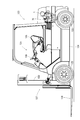
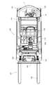
- the forklift car 120 includes a traveling machine body 124 having a pair of left and right front wheels 122 and a rear wheel 123.
- the traveling body 124 is equipped with a control unit 125 and a diesel engine 70.
- a working portion 127 having a fork 126 for handling work is provided on the front side portion of the traveling machine body 124.
- the control unit 125 is provided with a control seat 128 on which an operator is seated, a control handle 129, operation means for operating the diesel engine 70 and the like, a lever or switch as an operation means for the work unit 127, and the like. .
- a fork 126 is disposed on the mast 130, which is a component of the working unit 127, so as to be movable up and down.
- the fork 126 is moved up and down, a pallet (not shown) loaded with a load is placed on the fork 126, the traveling machine body 124 is moved forward and backward, and a cargo handling operation such as transportation of the pallet is performed. Yes.
Landscapes
- Engineering & Computer Science (AREA)
- Chemical & Material Sciences (AREA)
- Combustion & Propulsion (AREA)
- Mechanical Engineering (AREA)
- General Engineering & Computer Science (AREA)
- Exhaust Gas After Treatment (AREA)
- Processes For Solid Components From Exhaust (AREA)
- Exhaust Gas Treatment By Means Of Catalyst (AREA)
- Filtering Of Dispersed Particles In Gases (AREA)
Abstract
Description
2 ディーゼル酸化触媒(ガス浄化フィルタ)
3 スートフィルタ(ガス浄化フィルタ)
4 触媒内側ケース
5 触媒外側ケース
16 排気ガス入口管
16a 下向き開口端部
16b 上向き開口端部
19a~19e 支持脚体
20 フィルタ内側ケース
21 フィルタ外側ケース
34 排気ガス出口管
60 排気ガスの導入通路
70 ディーゼルエンジン
71 排気マニホールド
72 シリンダヘッド
Claims (6)
- エンジンからの排気ガスを浄化するガス浄化フィルタと、前記ガス浄化フィルタを内蔵した内側ケースと、前記内側ケースを内蔵した外側ケースとを備えている排気ガス浄化装置であって、
排気ガス入口を有する排気ガス入口管を備える構造であって、前記外側ケースの長手方向一端側に排気ガス流入口を設け、前記外側ケースの長手方向中途部に前記排気ガス入口管を配置し、前記排気ガス流入口に前記排気ガス入口管の排気ガス出口を接続するように構成したことを特徴とする排気ガス浄化装置。 - 前記排気ガス入口管の前記排気ガス入口側は、前記エンジンの排気マニホールドに取り付け向き変更可能に接続されていることを特徴とする請求項1に記載の排気ガス浄化装置。
- 前記外側ケースには、前記排気ガス流入口を覆い且つ前記外側ケースの長手方向に延びるように、前記排気ガス入口管が取り付けられていることを特徴とする請求項1に記載の排気ガス浄化装置。
- 前記外側ケースの外側面と前記排気ガス入口管の内側面とによって、排気ガスの導入通路が構成されていることを特徴とする請求項2に記載の排気ガス浄化装置。
- 前記排気ガス入口管の前記排気ガス入口側は、前記外側ケースの長手方向中央部に位置しており、前記外側ケースは、前記エンジンの一側にある冷却ファンと他側にあるフライホイールハウジングとの間に位置していることを特徴とする請求項1に記載の排気ガス浄化装置。
- 前記エンジンのシリンダヘッドには複数のフィルタ支持体が取り付けられており、前記外側ケースにおける長手方向一端側と長手方向他端側とは、前記各フィルタ支持体を介して前記シリンダヘッドに着脱可能に連結されていることを特徴とする請求項1に記載の排気ガス浄化装置。
Priority Applications (3)
| Application Number | Priority Date | Filing Date | Title |
|---|---|---|---|
| EP09814490.0A EP2333259B1 (en) | 2008-09-18 | 2009-09-07 | Exhaust gas purifying device |
| CN2009801364888A CN102159805B (zh) | 2008-09-18 | 2009-09-07 | 排气净化装置 |
| US12/737,932 US8683788B2 (en) | 2008-09-18 | 2009-09-07 | Exhaust gas purifying device |
Applications Claiming Priority (2)
| Application Number | Priority Date | Filing Date | Title |
|---|---|---|---|
| JP2008239402A JP5215789B2 (ja) | 2008-09-18 | 2008-09-18 | 排気ガス浄化装置 |
| JP2008-239402 | 2008-09-18 |
Publications (1)
| Publication Number | Publication Date |
|---|---|
| WO2010032645A1 true WO2010032645A1 (ja) | 2010-03-25 |
Family
ID=42039472
Family Applications (1)
| Application Number | Title | Priority Date | Filing Date |
|---|---|---|---|
| PCT/JP2009/065599 Ceased WO2010032645A1 (ja) | 2008-09-18 | 2009-09-07 | 排気ガス浄化装置 |
Country Status (6)
| Country | Link |
|---|---|
| US (1) | US8683788B2 (ja) |
| EP (1) | EP2333259B1 (ja) |
| JP (1) | JP5215789B2 (ja) |
| KR (1) | KR101583539B1 (ja) |
| CN (2) | CN103321719B (ja) |
| WO (1) | WO2010032645A1 (ja) |
Cited By (3)
| Publication number | Priority date | Publication date | Assignee | Title |
|---|---|---|---|---|
| WO2011154254A1 (de) * | 2010-06-10 | 2011-12-15 | Emitec Gesellschaft Für Emissionstechnologie Mbh | Abgasbehandlungsvorrichtung |
| CN109236447A (zh) * | 2018-11-15 | 2019-01-18 | 安徽安凯汽车股份有限公司 | 一种便于安装的汽车后处理装置 |
| CN110252735A (zh) * | 2019-07-05 | 2019-09-20 | 潍柴动力股份有限公司 | 一种dpf清洁设备 |
Families Citing this family (24)
| Publication number | Priority date | Publication date | Assignee | Title |
|---|---|---|---|---|
| JP5185751B2 (ja) * | 2008-09-18 | 2013-04-17 | ヤンマー株式会社 | 排気ガス浄化装置 |
| JP2011247231A (ja) * | 2010-05-31 | 2011-12-08 | Kubota Corp | 排気処理装置付きエンジンの造り分け方法 |
| JP5707178B2 (ja) * | 2011-03-02 | 2015-04-22 | フタバ産業株式会社 | 排気浄化装置 |
| JP5671444B2 (ja) * | 2011-12-05 | 2015-02-18 | 株式会社Ihiシバウラ | エンジン |
| US20140007562A1 (en) * | 2012-07-05 | 2014-01-09 | Julian JUSTIN | Exhaust system having an aftertreatment module |
| JP2014077383A (ja) * | 2012-10-10 | 2014-05-01 | Yanmar Co Ltd | コンバイン |
| US9133601B2 (en) * | 2012-10-16 | 2015-09-15 | Komatsu Ltd. | Hydraulic excavator |
| JP5414871B1 (ja) * | 2012-10-16 | 2014-02-12 | 株式会社小松製作所 | 油圧ショベル |
| JP5975859B2 (ja) * | 2012-11-29 | 2016-08-23 | ヤンマー株式会社 | エンジン装置 |
| JP6055305B2 (ja) * | 2012-12-26 | 2016-12-27 | ヤンマー株式会社 | 排気ガス浄化装置 |
| US8974740B2 (en) * | 2013-03-12 | 2015-03-10 | Tenneco Automative Operating Company Inc. | Exhaust treatment component mounting system |
| DE102013219640A1 (de) | 2013-09-27 | 2015-04-02 | Eberspächer Exhaust Technology GmbH & Co. KG | Abgasbehandlungseinrichtung |
| US9359930B2 (en) * | 2014-07-24 | 2016-06-07 | General Electric Company | System for an exhaust gas aftertreatment system and support structure |
| US10221756B2 (en) | 2014-07-24 | 2019-03-05 | Ge Global Sourcing Llc | System for an exhaust gas aftertreatment system and support structure |
| CA2964053A1 (en) * | 2014-10-15 | 2016-04-21 | Yanmar Co., Ltd. | Engine apparatus |
| US9797285B2 (en) * | 2015-06-15 | 2017-10-24 | Caterpillar Inc. | Unidirectional flow diesel particulate filter |
| US10287950B2 (en) * | 2015-11-03 | 2019-05-14 | Progress Rail Locomotive Inc. | Housing member for enclosing aftertreatment module of engine |
| US9657618B1 (en) * | 2015-11-03 | 2017-05-23 | Electro-Motive Diesel, Inc. | Aftertreatment system for engine |
| DE102016122769A1 (de) * | 2016-11-25 | 2018-05-30 | Eberspächer Exhaust Technology GmbH & Co. KG | Abgasbehandlungsanordnung |
| JP6731876B2 (ja) * | 2017-03-24 | 2020-07-29 | ヤンマーパワーテクノロジー株式会社 | エンジン装置 |
| WO2021020519A1 (ja) * | 2019-07-31 | 2021-02-04 | 株式会社クボタ | 作業車及びコンバイン |
| EP3792463B1 (de) * | 2019-09-16 | 2023-05-31 | Roth Technik Austria Gesellschaft Mit Beschränkter Haftung | Abgasnachbehandlungsvorrichtung mit durch lösen einer zerstörungsfrei lösbaren verbindung auswechselbaren abgasnachbgehandlungseinrichtungen |
| CN112228198B (zh) * | 2020-10-21 | 2021-09-07 | 马鞍山市常立发机械制造有限公司 | 一种节能环保型工程机械用柴油机 |
| CN112473312A (zh) * | 2020-10-28 | 2021-03-12 | 大连交通大学 | 一种用于甲醛治理的室内空气净化装置 |
Citations (5)
| Publication number | Priority date | Publication date | Assignee | Title |
|---|---|---|---|---|
| JP2000145430A (ja) | 1998-11-13 | 2000-05-26 | Ibiden Co Ltd | 排気ガス浄化装置 |
| JP2001173429A (ja) | 1999-12-17 | 2001-06-26 | Ibiden Co Ltd | 排気ガス浄化装置及び排気ガス浄化装置のヒータ制御方法 |
| JP2003027922A (ja) | 2001-07-13 | 2003-01-29 | Ibiden Co Ltd | 排気ガス浄化装置 |
| JP2007146681A (ja) * | 2005-11-24 | 2007-06-14 | Toyota Motor Corp | 内燃機関の排気装置 |
| JP2008082201A (ja) | 2006-09-26 | 2008-04-10 | Nissan Diesel Motor Co Ltd | エンジンの排気浄化装置 |
Family Cites Families (10)
| Publication number | Priority date | Publication date | Assignee | Title |
|---|---|---|---|---|
| JPS5042214A (ja) * | 1973-08-17 | 1975-04-17 | ||
| US4673423A (en) * | 1985-07-23 | 1987-06-16 | Mack Trucks, Inc. | Split flow particulate filter |
| KR100229731B1 (ko) | 1990-07-27 | 1999-11-15 | 브룬너 하인리히 페터 울리히 | 대형 디젤엔진 |
| JP4115120B2 (ja) | 2001-08-06 | 2008-07-09 | 株式会社小松製作所 | 内燃機関の排気ガス浄化装置 |
| DE10159158A1 (de) | 2001-12-01 | 2003-06-18 | Deutz Ag | Abgassammeldämpfer mit integriertem Abgasnachbehandlungssystem |
| US7047731B2 (en) * | 2002-02-27 | 2006-05-23 | Delphi Technologies, Inc. | Diesel particulate filter ash removal |
| JP2004340114A (ja) * | 2003-05-19 | 2004-12-02 | Hitachi Constr Mach Co Ltd | マフラ支持装置 |
| JP2005016374A (ja) | 2003-06-25 | 2005-01-20 | Yanmar Co Ltd | ディーゼル機関の消音器 |
| US6983728B1 (en) * | 2004-08-02 | 2006-01-10 | Cnh America Llc | Skid steer loader including muffler support for engine |
| JP2008031955A (ja) | 2006-07-31 | 2008-02-14 | Iseki & Co Ltd | ディーゼルエンジン |
-
2008
- 2008-09-18 JP JP2008239402A patent/JP5215789B2/ja active Active
-
2009
- 2009-09-07 US US12/737,932 patent/US8683788B2/en not_active Expired - Fee Related
- 2009-09-07 WO PCT/JP2009/065599 patent/WO2010032645A1/ja not_active Ceased
- 2009-09-07 EP EP09814490.0A patent/EP2333259B1/en not_active Not-in-force
- 2009-09-07 KR KR1020117006110A patent/KR101583539B1/ko active Active
- 2009-09-07 CN CN201310285419.1A patent/CN103321719B/zh not_active Expired - Fee Related
- 2009-09-07 CN CN2009801364888A patent/CN102159805B/zh not_active Expired - Fee Related
Patent Citations (5)
| Publication number | Priority date | Publication date | Assignee | Title |
|---|---|---|---|---|
| JP2000145430A (ja) | 1998-11-13 | 2000-05-26 | Ibiden Co Ltd | 排気ガス浄化装置 |
| JP2001173429A (ja) | 1999-12-17 | 2001-06-26 | Ibiden Co Ltd | 排気ガス浄化装置及び排気ガス浄化装置のヒータ制御方法 |
| JP2003027922A (ja) | 2001-07-13 | 2003-01-29 | Ibiden Co Ltd | 排気ガス浄化装置 |
| JP2007146681A (ja) * | 2005-11-24 | 2007-06-14 | Toyota Motor Corp | 内燃機関の排気装置 |
| JP2008082201A (ja) | 2006-09-26 | 2008-04-10 | Nissan Diesel Motor Co Ltd | エンジンの排気浄化装置 |
Non-Patent Citations (1)
| Title |
|---|
| See also references of EP2333259A4 |
Cited By (4)
| Publication number | Priority date | Publication date | Assignee | Title |
|---|---|---|---|---|
| WO2011154254A1 (de) * | 2010-06-10 | 2011-12-15 | Emitec Gesellschaft Für Emissionstechnologie Mbh | Abgasbehandlungsvorrichtung |
| CN109236447A (zh) * | 2018-11-15 | 2019-01-18 | 安徽安凯汽车股份有限公司 | 一种便于安装的汽车后处理装置 |
| CN109236447B (zh) * | 2018-11-15 | 2023-09-12 | 安徽安凯汽车股份有限公司 | 一种便于安装的汽车后处理装置 |
| CN110252735A (zh) * | 2019-07-05 | 2019-09-20 | 潍柴动力股份有限公司 | 一种dpf清洁设备 |
Also Published As
| Publication number | Publication date |
|---|---|
| EP2333259A1 (en) | 2011-06-15 |
| EP2333259A4 (en) | 2013-07-24 |
| KR20110058816A (ko) | 2011-06-01 |
| JP2010071178A (ja) | 2010-04-02 |
| CN102159805A (zh) | 2011-08-17 |
| KR101583539B1 (ko) | 2016-01-08 |
| JP5215789B2 (ja) | 2013-06-19 |
| US20110167807A1 (en) | 2011-07-14 |
| CN103321719B (zh) | 2015-07-29 |
| EP2333259B1 (en) | 2014-12-17 |
| US8683788B2 (en) | 2014-04-01 |
| CN103321719A (zh) | 2013-09-25 |
| CN102159805B (zh) | 2013-07-31 |
Similar Documents
| Publication | Publication Date | Title |
|---|---|---|
| JP5215789B2 (ja) | 排気ガス浄化装置 | |
| WO2010032646A1 (ja) | エンジン装置 | |
| JP5538700B2 (ja) | エンジン装置 | |
| JP5285366B2 (ja) | エンジン装置 | |
| WO2010032644A1 (ja) | 排気ガス浄化装置 | |
| WO2010032648A1 (ja) | エンジン装置 | |
| JP5285367B2 (ja) | エンジン装置 | |
| JP4963304B2 (ja) | 排気ガス浄化装置 | |
| JP2010071207A5 (ja) | ||
| JP5468106B2 (ja) | エンジン装置 | |
| JP5537689B2 (ja) | 排気ガス浄化装置 | |
| JP5580392B2 (ja) | エンジン装置 | |
| JP5825726B2 (ja) | 排気ガス浄化装置 | |
| JP5285369B2 (ja) | エンジン装置 | |
| JP5285368B2 (ja) | エンジン装置 | |
| JP2010071182A (ja) | 排気ガス浄化装置 | |
| JP5525088B2 (ja) | 排気ガス浄化装置及びエンジン装置 | |
| JP5923543B2 (ja) | 排気ガス浄化装置 | |
| JP5509258B2 (ja) | エンジン装置 | |
| JP5235575B2 (ja) | 排気ガス浄化装置 | |
| JP5285370B2 (ja) | エンジン装置 | |
| JP2014122634A (ja) | エンジン装置 | |
| JP5632508B2 (ja) | エンジン装置 | |
| JP2014077448A (ja) | エンジン装置 | |
| JP2013189986A (ja) | エンジン装置 |
Legal Events
| Date | Code | Title | Description |
|---|---|---|---|
| WWE | Wipo information: entry into national phase |
Ref document number: 200980136488.8 Country of ref document: CN |
|
| 121 | Ep: the epo has been informed by wipo that ep was designated in this application |
Ref document number: 09814490 Country of ref document: EP Kind code of ref document: A1 |
|
| WWE | Wipo information: entry into national phase |
Ref document number: 1656/DELNP/2011 Country of ref document: IN |
|
| ENP | Entry into the national phase |
Ref document number: 20117006110 Country of ref document: KR Kind code of ref document: A |
|
| NENP | Non-entry into the national phase |
Ref country code: DE |
|
| WWE | Wipo information: entry into national phase |
Ref document number: 12737932 Country of ref document: US |
|
| WWE | Wipo information: entry into national phase |
Ref document number: 2009814490 Country of ref document: EP |