WO2010032744A1 - エアバッグ及びその製造方法 - Google Patents
エアバッグ及びその製造方法 Download PDFInfo
- Publication number
- WO2010032744A1 WO2010032744A1 PCT/JP2009/066140 JP2009066140W WO2010032744A1 WO 2010032744 A1 WO2010032744 A1 WO 2010032744A1 JP 2009066140 W JP2009066140 W JP 2009066140W WO 2010032744 A1 WO2010032744 A1 WO 2010032744A1
- Authority
- WO
- WIPO (PCT)
- Prior art keywords
- vent hole
- cover
- airbag
- guide member
- portions
- Prior art date
- Legal status (The legal status is an assumption and is not a legal conclusion. Google has not performed a legal analysis and makes no representation as to the accuracy of the status listed.)
- Ceased
Links
Images








Classifications
-
- B—PERFORMING OPERATIONS; TRANSPORTING
- B60—VEHICLES IN GENERAL
- B60R—VEHICLES, VEHICLE FITTINGS, OR VEHICLE PARTS, NOT OTHERWISE PROVIDED FOR
- B60R21/00—Arrangements or fittings on vehicles for protecting or preventing injuries to occupants or pedestrians in case of accidents or other traffic risks
- B60R21/02—Occupant safety arrangements or fittings, e.g. crash pads
- B60R21/16—Inflatable occupant restraints or confinements designed to inflate upon impact or impending impact, e.g. air bags
- B60R21/23—Inflatable members
- B60R21/239—Inflatable members characterised by their venting means
-
- B—PERFORMING OPERATIONS; TRANSPORTING
- B60—VEHICLES IN GENERAL
- B60R—VEHICLES, VEHICLE FITTINGS, OR VEHICLE PARTS, NOT OTHERWISE PROVIDED FOR
- B60R21/00—Arrangements or fittings on vehicles for protecting or preventing injuries to occupants or pedestrians in case of accidents or other traffic risks
- B60R21/02—Occupant safety arrangements or fittings, e.g. crash pads
- B60R21/16—Inflatable occupant restraints or confinements designed to inflate upon impact or impending impact, e.g. air bags
- B60R21/23—Inflatable members
- B60R21/235—Inflatable members characterised by their material
- B60R2021/23571—Inflatable members characterised by their material characterised by connections between panels
- B60R2021/23576—Sewing
Definitions
- the present invention relates to an airbag that can be inflated and deployed between a seated occupant and a vehicle body by introducing gas generated by an inflator.
- Some airbags regulate gas release from the vent hole by covering the vent hole provided in the airbag with a vent hole cover when the airbag is deployed with the gas introduced from the inflator.
- the vent hole cover is supported by a cover guide member in the vicinity of the vent hole so as not to be displaced with respect to the vent hole (see, for example, Patent Document 1).
- the vent hole cover regulates the release of gas until the airbag is deployed in a shape that can restrain the occupant.
- the sewing thread that holds the vent hole cover breaks.
- the vicinity of the vent hole is supported by the cover guide member so that the vent hole cover is not displaced with respect to the vent hole.
- the cover guide member does not support the portion corresponding to the vent hole (that is, the portion blocking the vent hole), the portion corresponding to the vent hole is not displaced from the vent hole (not to be displaced). ) It is difficult to support.
- An object of the present invention is to provide an air bag capable of regulating the displacement of the vent hole cover with respect to the vent hole and appropriately discharging gas from the vent hole.
- an airbag includes an inflator and an airbag provided with a vent hole that can be deployed by a gas introduced from the inflator and can release the gas to the outside.
- An airbag covers the vent hole, covers a vent hole cover that can be moved to open the vent hole with a predetermined internal pressure generated in the airbag, and covers the vent hole cover.
- a cover guide member that allows the vent hole to move so as to open the vent hole with an internal pressure of the airbag, and an airbag in which an opening is formed in a portion corresponding to the vent hole in the cover guide member.
- the vent hole cover includes an extending portion extending from a portion corresponding to the inflator, and an orthogonal portion extending in a direction substantially orthogonal to the extending portion from a distal end of the extending portion. And is formed in a substantially T shape at the extension part and the orthogonal part, and an intersection part where the extension part and the orthogonal part intersect is formed so as to correspond to the vent hole,
- the cover guide member is extended toward both sides of the intersecting portion so as to face the orthogonal portion.
- the cover guide member has a distance dimension from the tip of the cover guide member to the vent hole, and the distance dimension is a length dimension from the tip of the cover guide member to the tip of the vent hole cover. It is set to be larger.
- the cover guide member is formed such that a tip thereof is inclined with respect to the orthogonal portion.
- the extension part has a first side edge
- the orthogonal part has a second side edge
- the corner edge substantially coincides with the periphery of the opening of the cover guide member.
- the cover guide member is stitched to the base fabric of the airbag, and has a stress concentration suppressing portion for suppressing concentration of stress on the stitched end of the cover guide member at each stitched end.
- each of the stress concentration suppressing portions is formed in an arc shape.
- an airbag manufacturing method formed by joining two base fabrics, the step of forming a vent hole in one of the two base fabrics, Joining a vent hole cover that covers the vent hole to a base cloth having a vent hole formed thereon, joining a cover guide member that regulates movement of the vent hole cover to the base cloth having the vent hole formed thereon, and A method of manufacturing an airbag including a step of joining the periphery of two base fabrics.
- the two base fabrics are sewn with a breakable suture so that the end of the vent hole cover is attached to the two base fabrics.
- the method further includes fixing to the cloth.
- each of the base cloth, the vent hole cover, and the cover guide member in which the vent hole is formed is formed of a sheet of the same material having friction characteristics different from each other, and the front surface and the back surface of the sheet are between the members. Arrange to face each other.
- the airbag according to the airbag device of the present invention includes a vent hole cover that covers the vent hole. Furthermore, the cover guide member which covers a vent hole cover was provided. Therefore, the position shift of the vent hole cover with respect to the vent hole can be regulated by the cover guide member. Thereby, it is possible to prevent the gas from being released from the vent hole before the airbag is deployed to a shape that can be restrained. Therefore, it is possible to appropriately release gas from the vent hole, and the airbag can be deployed well.
- an opening was formed in a portion of the cover guide member corresponding to the vent hole. Therefore, the internal pressure of the airbag can be applied to the vent hole cover through the opening. Thereby, when the airbag bag body rises to a predetermined internal pressure, the vent hole cover can be moved at a predetermined internal pressure so as to open the vent hole. Therefore, a gap is formed between the vent hole cover and the vent hole, and the internal pressure of the airbag bag body can be appropriately adjusted by discharging gas to the outside through the formed gap.
- the vent hole cover was formed in a substantially T shape at the extending portion and the orthogonal portion, and the intersection of the extending portion and the orthogonal portion was made to correspond to the vent hole. Then, the cover guide member was extended toward both sides of the intersecting portion so as to face the orthogonal portion. Therefore, the intersection corresponding to the vent hole can be covered with the cover guide member, and both sides of the intersection can be covered with the cover guide member. Thereby, the position shift of the vent hole cover with respect to the vent hole can be more effectively regulated by the cover guide member.
- the distance dimension from the tip of the cover guide member to the vent hole is made larger than the length dimension from the tip of the cover guide member to the tip of the vent hole cover (that is, the length dimension of the exposed portion). . Therefore, when the exposed part is folded back toward the opening in the developing process, the exposed part can be prevented from reaching the opening and being drawn into the opening. Thereby, the vent hole cover can be reliably moved so as to open the vent hole.
- the tip of the cover guide member was formed so as to be inclined with respect to the orthogonal portion. Therefore, in the unfolding process, the folded-back direction of the exposed part is regulated so as to be inclined with respect to the moving direction at the left and right ends. Thereby, when the folded part hits the front-end
- the distance from the corner edge where the side edge of the extension part and the side edge of the orthogonal part intersect to the periphery of the vent hole is set smaller than the distance from the other part of the vent hole cover to the periphery of the vent hole. . Therefore, when the gap is formed between the other part of the vent hole cover and the vent hole, the gap can be favorably formed between the corner edge and the vent hole. Thereby, gas can be favorably discharged from the formed gap to suppress the deformation of the vent hole cover, and the internal pressure of the airbag can be suitably adjusted.
- an opening is formed in a portion of the cover guide member corresponding to the vent hole, and the periphery of the opening is substantially coincided with the corner edge. Therefore, it is possible to prevent the corner edge from being covered with the cover guide member. Thereby, gas can be discharged
- the cover guide member has a stress concentration suppressing portion at each stitched end, it is possible to prevent the cover guide member from being peeled off from the base fabric of the airbag.
- the stress concentration suppressing portion is formed in an arc shape, interference between the guide member and the vent hole cover can be prevented, and smooth movement of the vent hole cover can be realized.
- two base cloths can be joined after all functional parts such as a vent hole cover and a guide member are arranged on one base cloth side.
- the vent hole cover since the end portion of the vent hole cover is fixed to the two base cloths after the vent hole cover is fixed to one base cloth, the vent hole cover is not easily displaced.
- vent hole cover Since the front and back surfaces of the base fabric, vent hole cover, and guide member in which vent holes are formed differ in the frictional characteristics of the sheets, the frictional characteristics (slip characteristics) between each member are reduced. It can be made uniform. As a result, it is possible to manufacture an airbag having a deployment characteristic within a predetermined range.
- FIG. 1 is a perspective view of a vehicle equipped with an airbag according to the present invention. It is a rear view of an airbag.
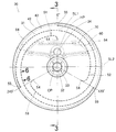
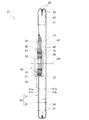
- FIG. 3 is a cross-sectional view taken along line 3-3 in FIG. 2.
- FIG. 3 is an exploded perspective view of the airbag shown in FIG. 2. It is sectional drawing of the stitching
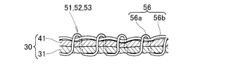
- FIG. 6 is a cross-sectional view taken along line 6-6 in FIG. It is a front view of a vent hole cover and a cover guide member.
- FIG. 8 is an exploded front view of the vent hole cover and cover guide member shown in FIG. 7.
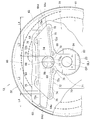
- FIG. 7 is an enlarged view showing a part of the vent hole cover shown in FIG. 6.
- a vehicle airbag device 13 is housed in a steering wheel 12 disposed in front of the driver's seat 11. When collision energy acts on the vehicle 10, the airbag device 13 is deployed on the front side of the driver to restrain and protect the driver (occupant).
- the airbag device 13 includes an inflator 20 that generates high-pressure gas, an airbag 30 into which the gas generated by the inflator 20 is introduced, and the airbag 30 as a steering wheel 12.
- a retainer 22 and a fixing ring 23 attached to (FIG. 1) are provided.
- the inflator 20 is attached to the steering wheel 12 with a retainer 22 and a fixing ring 23, and generates high-pressure gas (hereinafter referred to as “gas”) when collision energy acts on the vehicle 10 (FIG. 1). Is supplied into the airbag 30.
- gas high-pressure gas
- the bolt 24 is inserted into the mounting hole formed in the mounting flange 21 of the inflator 20 and the mounting hole of the fixing ring 23 disposed in the airbag 30.
- the inflator 20 is fixed to the steering wheel 12 by fastening the bolt 24 with a nut.
- the retainer 22 is a member provided on the steering wheel 12.
- the airbag 30 covers a first base cloth 31 having a circular outer shape, a second base cloth 41 having a circular outer shape, and a vent hole 34 (described later) of the first base cloth 31.
- a vent hole cover 60, a cover guide member 70 that suppresses displacement of the vent hole cover 60, and first, second, and third reinforcing sheets 81, 82, and 83 are provided.
- the airbag 30 has a circular bag body in which the first base fabric 31 and the second base fabric 41 are overlapped and the respective outer peripheral portions 42 are joined (sewn together at the outer peripheral stitching portion 43). Is formed and can be deployed by introducing gas from the inflator 20.
- the first base fabric 31 is a seat positioned on the front side of the vehicle body so as to face the steering wheel 12 (FIG. 1) when the airbag 30 is deployed.
- the first base fabric 31 is formed with an inflator insertion hole 32 for inserting the inflator 20, a plurality of bolt holes 33 for attaching the inflator 20, and a vent hole 34 for releasing (releasing) gas.
- the inflator insertion hole 32 is formed coaxially with the center CP of the first base fabric 31.
- the inflator insertion hole 32 is a circular through hole that can guide the tip of the inflator 20 into the airbag 30. By guiding the tip of the inflator 20 into the airbag 30, the gas generated in the inflator 20 is introduced into the airbag 30.
- the plurality of bolt holes 33 are through holes that are provided around the inflator insertion holes 32 and into which the bolts 24 can be inserted.
- the vent hole 34 is, for example, a circular through hole that discharges a part of the gas introduced into the airbag 30 to adjust the bag internal pressure (internal pressure due to gas) of the deployed airbag 30. .
- the vent hole 34 is disposed at a position HP (hole center HP) offset from the center CP of the inflator insertion hole 32 by a predetermined distance.
- the second base cloth 41 is a seat that is formed in substantially the same circular shape as the first base cloth 31, and is positioned on the rear side of the vehicle body so as to face the occupant when the airbag 30 is deployed.
- the airbag 30 has a first reinforcing sheet 81 superimposed on the surface of the first base fabric 31, and a second reinforcing sheet 82 and a vent hole cover 60 on the back surface of the first base fabric 31.
- the cover guide member 70 and the third reinforcing sheet 83 are overlapped in this order, and the respective members are sewn together so as to be integrated around the inflator insertion hole 32.
- the first and second base fabrics 31 and 41, the vent hole cover 60, the cover guide member 70, and the first, second, and third reinforcing sheets 81, 82, and 83 are all made of the same material and have the same thickness. (Or a flexible panel).
- These cloths have different friction characteristics (friction resistance) on the front surface (one surface) and the back surface (the other surface).
- the friction characteristics are different between the front and back surfaces by applying a silicone coating only to one side of the fabric.
- the first base fabric 31 and the vent hole cover 60, and the vent hole cover 60 and the cover guide member 70 are arranged so that the front surface and the back surface of the first fabric 31 and the back surface face alternately.
- the friction resistance of the first base fabric 31 is larger on the back surface (the surface facing the second base fabric 41) than on the front surface.
- the surface of the vent hole cover 60 with low frictional resistance faces the back surface (surface with low frictional resistance) of the first base fabric 31.
- the surface of the vent hole cover 60 with high frictional resistance faces the surface of the cover guide member 70 with low frictional resistance.
- the first reinforcing sheet 81, the second reinforcing sheet 82, the vent hole cover 60, the cover guide member 70, and the third reinforcing sheet 83 have bolt holes coaxially with respect to the plurality of bolt holes 33 of the first base cloth 31, respectively. Is formed.
- the first reinforcing sheet 81, the first base cloth 31, the second reinforcing sheet 82, the vent hole cover 60, the cover guide member 70, and the third reinforcing sheet 83 that are integrally stitched together are the inflator 20 (specifically, the attachment). It is sandwiched between the flange 21) and the fixing ring 23. In this state, the bolt hole of the mounting flange 21 and the bolt hole of the fixing ring 23 are arranged coaxially with respect to each of the plurality of bolt holes 33 of the first base fabric 31.
- the air bag 30 is attached to the mounting flange 21 of the inflator 20 by inserting the bolt 24 into the bolt hole 33 and other bolt holes and screwing them together.
- the airbag 30 is supported by the retainer 22 via the attachment flange 21.
- the airbag 30 has a plurality of, for example, three stitched portions 51 and 52 in a state where the first base cloth 31 and the second base cloth 41 (FIG. 4) are overlapped. , 53.
- the stitched portions 51, 52, and 53 are stitched in a spiral shape from each stitching start point 54 near the center CP of the inflator insertion hole 32 to a stitching end point 55 on the outer peripheral portion 42.
- the stitching start point 54 located at the radially inner end extends toward the center CP of the airbag bag body 30. Therefore, stress can be concentrated on the stitching start point 54 by the bag internal pressure of the airbag 30.
- the breaking suture portions 51, 52, and 53 have the same configuration, and the length from the stitching start point 54 to the stitching end point 55 is the same, and the phases are shifted from each other by 120 °. That is, the breaking suture parts 51, 52, and 53 all have the same distance from the center CP of the inflator insertion hole 32 to the stitching start point 54, and the distances from the center CP to the stitching end point 55 are all the same.
- a straight line extending from the center CP of the inflator insertion hole 32 through the center of the hole center HP toward the direction of 0 ° is defined as a reference line SL1.
- a straight line orthogonal to the reference line SL1 on the surface of the first base fabric 31 is defined as an orthogonal reference line SL2.
- the first breaking suture portion 51 has a azimuth 0 ° as a stitching start point 54, and is slightly stitched outward in the radial direction while slightly extending outward from the stitching start point 54, and then stitched in a circular arc shape. It is sewn in a spiral shape by an angle of 120 °, and an azimuth of 120 ° is a stitching end point 55.
- the stitching start point 54 is located radially outward from the vent hole 34.
- the stitching end point 55 is formed before reaching the outer peripheral edge of the base fabric 31, 41, thereby allowing gas to flow between the end point and the outer peripheral edge.
- the second breaking suture part 52 is stitched in a spiral shape by 240 ° in the counterclockwise direction along the outer periphery of the first breaking suture part 51 with the azimuth 120 ° as the stitching start point 54.
- the azimuth 240 ° is the stitching end point 55.
- the third breaking suture portion 53 is sewn in a spiral shape by 240 ° counterclockwise along the outer periphery of the second breaking suture portion 52 with the orientation 240 ° as the sewing start point 54.
- the azimuth 0 ° is the stitching end point 55.
- the breaking suture parts 51, 52, 53 are spaced apart from each other with a predetermined interval in the radial direction. This interval gradually decreases as the stitching start point 54 advances to the stitching end point 55.
- the stitched portions 51, 52, and 53 are sequentially broken from each stitching start point 54 toward each stitching end point 55 on the outer peripheral side by the internal pressure of the bag generated when the airbag 30 is deployed. By breaking the stitched portions 51, 52, and 53, it is possible to increase the volume of the airbag 30 and adjust the internal pressure of the airbag 30.
- each of the breaking suture portions 51, 52, 53 has first and second sutures 56, which are sequentially broken from the center portion of both base fabrics 31, 41 toward the outer peripheral portion.
- the second base fabrics 31 and 41 are separated.
- the suture thread 56 includes a first thread 56a and a second thread 56b.
- the first yarn 56a is subjected to a coloring process such that the yarn is fragile so as to be broken by a bag internal pressure of a predetermined level or more, for example, a tensile strength (a breaking load that is a force required for pulling and breaking) is 20N to 60N.
- a tensile strength (a breaking load that is a force required for pulling and breaking) is 20N to 60N.
- the second thread 56b is a thread that guides the first thread 56a in the stitching direction of the breaking suture portions 51, 52, and 53, and is not broken by the bag internal pressure when the airbag bag body 30 is deployed. Further, the tensile strength is set to be larger than that of the first yarn 56a.
- the first thread 56a is first broken by the tension acting on the first thread based on the bag internal pressure of a predetermined level or more. Moreover, the first thread 56a is guided in the stitching direction by the second thread 56b. Therefore, the breaking strength of the first thread 56a is kept substantially constant at any location in each of the breaking suture portions 51 to 53. Accordingly, the first yarn 56a is appropriately and sequentially broken from the central portion toward the outer peripheral portion of the first and second base fabrics 31 and 41.
- the airbag 30 can be deployed more smoothly and with good timing by the gas supplied from the inflator 20. For this reason, the change of the bag internal pressure can be controlled more appropriately.
- the internal pressure characteristics of the airbag 30 after starting the supply of gas from the inflator 20 to the airbag 30 can be made more accurate.
- the first yarn 56a is made of a filament yarn (filament yarn) which is a continuous long fiber, and has no or almost no twist. Since there is no twist, there is little variation in breaking load in the length direction of the yarn. Accordingly, the first yarn 56a is accurately and sequentially broken from the central portion toward the outer peripheral portion of the first and second base fabrics 31 and 41 by a bag internal pressure of a predetermined level or more.
- the vent hole cover 60 covers the vent hole 34, so that the vent hole 34 can be closed until the bag internal pressure of the airbag 30 reaches a predetermined value.
- the bag internal pressure of the body 30 reaches a predetermined value, it is a sheet-like flap that can move so as to open the vent hole 34 with the bag internal pressure.
- the vent hole cover 60 includes an annular cover base 61 attached to the first base fabric 31 with bolts 24... And a vertical belt-like extension portion extending radially from the cover base 61 toward the vent hole 34. 62 and a transverse band-like orthogonal part 63 provided at the tip of the extension part 62.
- the vent hole cover 60 is formed in a substantially T shape by the extension part 62 and the orthogonal part 63, and the intersection part 66 of the extension part 62 and the orthogonal part 63 is formed so as to correspond to the vent hole 34.
- the vent hole cover 60 is formed symmetrically with respect to the reference line SL1 shown in FIG.
- the cover base 61 is an annular portion that is coaxially provided at the center CP of the inflator insertion hole 32 (see also FIG. 4), and is coaxial with the inflator insertion hole 32 and has a substantially identical diameter. 67.
- the cover base 61 is sewn to the first base cloth 31 around the inflator insertion hole 32.
- the extending portion 62 extends along the back surface of the first base fabric 31 from a cover base portion 61 (that is, the inflator 20 side shown in FIG. 4) toward the vent hole 34 with a predetermined width. It is.
- the orthogonal part 63 extends along the back surface of the first base fabric 31 from the front end 62a of the extension part 62 in a direction substantially orthogonal to the extension part 62 (that is, both right and left). It is a part.
- the orthogonal part 63 includes a crossing part 66 provided above the extension part 62, a left belt-like part 64 extending substantially horizontally from the crossing part 66 in the left direction, and substantially horizontal in the right direction from the crossing part 66. And a right belt-like portion 64 extended to the right.
- the upper edges 66a, 64b, 64b of the intersecting portion 66 and the left and right belt-like portions 64 are continuously extended on the same horizontal line. That is, the upper edge of the orthogonal part 63 is formed substantially parallel to the orthogonal reference line SL2 shown in FIG.
- the lower edge 64c of the left belt-like portion 64 extends in a taper shape with an upward slope from the intersecting portion 66 toward the left tip.
- the lower edge 64c of the right belt portion 64 extends in a taper shape with an upward slope from the intersecting portion 66 toward the right tip.
- the tip 64 d of the left belt-like portion 64 is formed in an inclined shape along the stitched portion 43 of the airbag 30.
- the distal end 64 d of the right belt portion 64 is formed in an inclined shape along the stitched portion 43 of the airbag 30.
- the distal end portions of the left and right belt-like portions 64, 64 (that is, both end portions of the orthogonal portion 63) 64a, 64a are exposed from the cover guide member 70 and can be broken by the stitched portions 51, 52, 53.
- the base fabrics 31 and 41 are sewn. That is, the tip portions 64a and 64a of the left and right belt-like portions 64 and 64 are “exposed portions”.
- a concave left corner edge 68 is formed at a portion where the left side edge 62b of the extending part 62 and the lower edge 64c of the left belt-like part 64 intersect.
- the left corner distance from the left corner edge 68 to the peripheral edge 34a of the vent hole 34 is set to L1.
- a concave right corner edge 69 is formed at a portion where the right edge 62b of the extending part 62 and the lower edge 64c of the right belt part 64 intersect.
- the right corner distance from the right corner edge 69 to the peripheral edge 34a of the vent hole 34 is set to L1 similarly to the left corner distance.
- the upper edge distance from the upper edge (other part of the vent hole cover 60) 66a to the peripheral edge 34a of the vent hole 34 is set to L2.
- the left corner distance L1 and the right corner distance L1 are set smaller than the upper edge distance L2.
- the left corner edge 68 and the right corner edge 69 are supported by the extension 62. Therefore, when the left corner edge 68 and the right corner edge 69 are pulled into the vent hole 34 by the bag internal pressure of the airbag 30, it is considered that the extension portion 62 prevents the left corner edge 68 and the right corner edge 69 from being pulled in. .
- the left corner distance L1 and the right corner distance L1 were set smaller than the upper edge distance L2. Therefore, when the gap is formed between the upper edge 66a of the intersecting portion 66 and the vent hole 34, a good gap is formed between the left corner edge 68 and the vent hole 34, and the right corner edge 69 and the vent hole 34 are bent. A good gap can be formed between the holes 34. Thereby, gas can be discharged
- the cover guide member 70 covers the covered portion 85 in order to prevent the crossing portion 66 of the vent hole cover 60 from being displaced with respect to the vent hole 34, and the vent hole This is a sheet that allows the cover 60 to move so as to open the vent hole 34.
- the covered portion 85 of the vent hole cover 60 is a portion obtained by removing the tip end portion (exposed portion) 64a of the left belt portion 64 and the tip portion (exposed portion) 64a of the right belt portion 64 from the vent hole cover 60.
- the hole closing portion 86 is formed at the intersection 66.
- the cover guide member 70 covering the covered portion 85 is provided at the upper end of the guide base 71 and an annular guide base 71 attached to the first base cloth 31 with bolts 24 via bolt holes 33 (FIG. 4). It consists of a horizontal belt-shaped guide part 72.
- the cover guide member 70 is formed symmetrically with respect to the reference line SL1 shown in FIG.
- the guide base 71 is an annular portion provided coaxially at the center CP of the inflator insertion hole 32 (see also FIG. 4), similar to the cover base 61 of the vent hole cover 60, with respect to the inflator insertion hole 32.
- a through hole 87 is provided which is coaxial and has substantially the same diameter.
- the guide base 71 is integrally stitched to the first base cloth 31 around the inflator insertion hole 32.
- the guide base 71 can be extended to the vicinity of the inflator 20 by sewing the guide base 71 around the inflator insertion hole 32. Thereby, adjustment of the relative position of the inflator 20 and the cover guide member 70 becomes easy, and manufacturing accuracy improves.
- the guide portion 72 is a horizontal belt-like portion extending in the left-right direction from the upper end 71a of the guide base portion 71 along the back surface of the first base fabric 31.
- the guide part 72 is overlapped with the orthogonal part 63 of the vent hole cover 60, the upper side part 72 b is stitched to the first base cloth 31 by the first stitching part 73, and the lower left side part 72 c is first stitched by the second stitching part 74.
- the lower right side portion 72d is sewn to the first base fabric 31 by the third stitching portion 75.
- the guide portion 72 extends to the vicinity of the breaking suture portions 51 to 53 (FIG. 2), and the left and right tips 72 a and 72 a are opened without being stitched to the first base fabric 31.
- a left belt portion 64 is disposed between the left portion of the first suture portion 73 and the second suture portion 74, and the distal end portion (exposed portion) 64 a of the left belt portion 64 extends from the left distal end 72 a to the outside of the guide portion 72. Is protruding.
- the right belt portion 64 is disposed between the right portion 73a of the first suture portion 73 and the third suture portion 74, and the distal end portion (exposed portion) 64a of the right belt portion 64 extends from the right distal end 72a to the guide portion 72. It protrudes to the outside.
- the guide portion 72 extends toward the right and left sides (both sides) of the intersecting portion 66 so as to face the orthogonal portion 63 (the left and right belt-like portions 64).
- an opening 77 is formed in a circular shape at a portion 88 corresponding to the hole closing portion 86.
- the peripheral edge 77a of the opening 77 substantially coincides with the concave left corner edge 68 and the concave right corner edge 69 (FIG. 7). Therefore, the concave left corner edge 68 and the concave right corner edge 69 can be prevented from being covered with the cover guide member 70.
- the opening 77 is formed coaxially with the vent hole 34.
- the first, second, and third stitching portions 73, 74, and 75 are guide portions that regulate the direction in which the orthogonal portion 63 of the vent hole cover 60 moves (slides). Therefore, when the orthogonal part 63 of the vent hole cover 60 moves (slides), the orthogonal part 63 is guided by the three stitching parts 73, 74, and 75 for guide and the moving direction of the orthogonal part 63 is restricted.
- the first stitching portion 73 is sewn from the vicinity of the left tip 72a to the vicinity of the right tip 72a along the upper side 72b of the guide portion 72. In other words, the first stitching portion 73 is stitched substantially parallel to the upper edge of the guide portion 72.
- the second stitching portion 74 is stitched from the vicinity of the left tip 72a to the vicinity of the left edge 62b (FIG. 9) of the extending portion 62 along the lower left side portion 72c of the guide portion 72.
- the second stitching portion 74 is sewn so as to be inclined downward so as to approach the inflator insertion hole 32 from the vicinity of the left tip 72a to the vicinity of the left edge 62b.
- the third stitching portion 75 is stitched from the vicinity of the right tip 72a to the vicinity of the right edge 62b of the extending portion 62 along the lower right side portion 72d of the guide portion 72.
- the third stitching portion 75 is sewn so as to be inclined downward so as to approach the inflator insertion hole 32 from the vicinity of the right tip 72a to the vicinity of the right edge 62b.
- the first to third suture portions 73 to 75 have stress concentration suppressing portions 76 and 76 at the suture ends on both sides, respectively.
- the stress concentration suppressing portions 76 and 76 of the first stitching portion 73 are formed on the upper side of the first stitching portion 73.
- the stress concentration suppressing portions 76 and 76 of the second and third suture portions 74 and 75 are respectively formed below the second and third guide suture portions 74 and 75.
- the stress concentration suppressing portions 76 and 76 of the first to third stitching portions 73 to 75 are stitched in a loop shape in a direction away from the vent hole cover 60.
- the stress concentration suppressing portions 76 and 76 are formed in a substantially oval shape, that is, a curved shape so as to follow the first to third stitched portions 73 to 75.
- the first to third stitching portions 73 to 75 can be prevented from breaking from the stress concentration suppressing portions 76 and 76, and the vent hole cover 60 can be moved (slid) smoothly.
- the guide part 72 of the cover guide member 70 is extended so as to face the orthogonal part 63 (the left and right belt-like parts 64), and the upper side part 72b is stitched to the first base cloth 31 by the first stitching part 73, The left and right lower side portions 72c and 72d are stitched to the first base cloth 31 by the second and third stitching portions 74 and 75. Therefore, the cover guide member 70 can regulate the positional displacement of the covered portion 85 of the vent hole cover 60 with respect to the vent hole 34.
- the intersection 66 corresponding to the vent hole 34 (specifically, a portion of the intersection 66 excluding a portion corresponding to the opening 77) can be covered with the cover guide member 70. Therefore, the position deviation of the vent hole cover 60 with respect to the vent hole 34 can be reliably regulated by the cover guide member 70.
- an opening 77 is formed in a portion of the cover guide member 70 corresponding to the hole closing portion 86. Therefore, the bag internal pressure of the airbag 30 can be applied to the hole closing portion 86 through the opening 77.
- the orthogonal portion 63 of the vent hole cover 60 can be moved by the bag internal pressure so as to open the vent hole 34. Therefore, the vent hole cover 60 is pushed into the vent hole 34, and the vent hole cover 60 around the vent hole 34 enters a wavy state, and a gap is formed between the vent hole cover 60 and the first base fabric 31. The gap is formed and communicates with the vent hole 34.
- the internal pressure of the airbag 30 can be appropriately adjusted by discharging the gas from the vent hole to the outside through the gap.
- the left distance dimension from the left tip 72a of the guide part 72 to the vent hole 34 is set to L3
- the distance dimension from the right tip 72a of the guide part 72 to the vent hole 34 is set to L3.
- the left length dimension of the exposed portion (that is, the tip portion) 64a from the left tip 72a of the guide portion 72 to the tip 64d of the left belt-like portion 64 is set to L4.
- the right length dimension of the exposed portion (ie, the tip portion) 64a from the right tip 72a to the tip 64d of the right belt-like portion 64 is set to L4.
- the left distance dimension L3 is set larger than the left length dimension L4, and the right distance dimension L3 is set larger than the right length dimension L4.
- the guide part 72 is formed so that the left and right ends 72a of the guide part 72 are inclined with respect to the orthogonal part 63 of the vent hole cover 60, respectively.
- the exposed portion (that is, the tip portion) 64a of the left belt-like portion 64 is folded back in a state inclined at the left tip 72a with respect to the moving direction.
- the airbag 30 is integrally stitched with stitched portions 51 to 53 (see FIG. 10 for the stitched portion 52) where the first and second base fabrics 31, 41 can be broken. Therefore, the left and right tip portions 64a and 64a (see FIG. 10 for the right tip portion 64a) of the vent hole cover 60 are constrained to the first and second base cloths 31 and 41 by the stitched portions 51 to 53. .
- the cover guide member 70 restricts the position 85 of the vent hole cover 60 from being displaced relative to the vent hole 34.
- a crossing portion 66 corresponding to the vent hole 34 (specifically, a portion of the crossing portion 66 excluding a portion corresponding to the opening 77) is covered with the cover guide member 70.
- the first base fabric 31 and the second base fabric 41 are stitched together by the stitching portions 51 to 53, and the gas is prevented from being discharged from the vent hole 34, so that the airbag 30 is in the initial stage of deployment.
- the expansion volume is regulated. Therefore, the airbag 30 quickly reaches a uniform membrane pressure distribution within a restricted volume between the central part and the stitched parts 51 to 53.
- the airbag 30 gradually expands in volume and maintains a predetermined shape while maintaining an appropriate bag internal pressure.
- FIG. 12A and 12B show a state in which the airbag 30 is deployed.
- the stitching portions 51 to 53 (FIG. 10) are broken, so that the airbag 30 can be deployed into a predetermined shape while keeping the bag internal pressure of the airbag 30 at a suitable level.
- the left and right belt-like portions 64, 64 move (drawn) as indicated by an arrow C, whereby the hole closing portion 86 is pushed out of the airbag 30 from the vent hole 34.
- the left corner distance L1 and the right corner distance L1 are set smaller than the upper edge distance L2. Therefore, when the gap is formed between the upper edge 66a of the intersecting portion 66 and the vent hole 34, the deformation of the intersecting portion 66 is suppressed and the gap is favorably formed between the left corner edge 68 and the vent hole 34. In addition, a gap can be formed favorably between the right corner edge 69 and the vent hole 34.
- the peripheral edge 77a of the opening 77 substantially coincides with the concave left corner edge 68 and the concave right corner edge 69. Therefore, the concave left corner edge 68 and the concave right corner edge 69 can be prevented from being covered with the cover guide member 70.
- FIG. 13 shows an example in which gas is discharged from the vent hole 34 of the airbag 30 to the outside.
- a good gap is formed between the left and right corner edges 68 and 69 and the vent hole 34, and the left and right corner edges 68 and 69 are not covered with the cover guide member 70. . Accordingly, excess gas in the airbag 30 can be discharged well as indicated by an arrow D from the gap between the left and right corner edges 68 and 69 and the vent hole 34 as shown in FIG. By discharging the surplus gas to the outside satisfactorily, an excessive increase in the bag internal pressure of the airbag 30 can be prevented and the bag internal pressure can be suitably adjusted even after the airbag 30 reaches its maximum shape.
- the tip portions (exposed portions) 64a, 64a of the left and right belt-like portions 64, 64 are folded back.
- the tip 64a is folded back toward the opening 77, the folded tip 64a can be prevented from reaching the opening 77 and being drawn into the opening 77,
- the vent hole cover 60 can be smoothly moved so as to open the vent hole 34.
- FIGS. 14A and 14B show the stress concentration suppressing portion of the cover guide member shown in FIG.
- the first to third guide stitching portions 73 to 75 have stress concentration suppressing portions 76 and 76 at stitched ends on both sides, respectively.
- the stress concentration suppressing portions 76 and 76 are further looped in the direction away from the vent hole cover 60 at the respective suture ends of the guide suture portions 73 to 75. It is the part which was sewn to.
- the stress concentration suppressing portions 76 and 76 are formed in an approximately oval shape elongated in a front view in the direction along the respective guide stitching portions 73 to 75. For this reason, each stitching end exhibits an arc shape.
- the stress concentration suppressing portion 76 is separated from the vent hole cover 60 at the end of the main stitching portion 73a.
- a first arc portion 76a stitched in a semicircular arc shape toward the head, a first straight portion 76b stitched linearly from the first arc portion 76a, and a direction approaching the vent hole cover 60 from the first straight portion 76b.
- a second arc portion 76c sewn in a semicircular arc shape toward the head, and a second straight portion 76d sewn straight from the second arc portion 76c and along the main stitching portion 73a.
- the stress concentration suppressing portion 76 formed in the second and third guide suturing portions 74 and 75 is the same as the stress concentration suppressing portion 76 of the first guide suturing portion 73 as shown in FIG. is there.
- the second and third guide stitching portions 74 and 75 also have main stitching portions 74a and 75a, respectively.
- FIG. 15A shows a cover guide member that does not have a stress concentration suppressing portion for comparison with the present embodiment
- FIG. 15B shows this embodiment having a stress concentration suppressing portion.
- An example cover guide member is shown.
- the airbag 300 shown in FIG. 15A is provided with a vent hole cover 301 that covers the vent hole 309 and a cover guide member 302 that guides the vent hole cover 301.
- the cover guide member 302 is stitched to a base fabric (not shown) of the airbag bag body 300 by first to third guide stitching portions 303 to 305.
- first to third guide stitching portions 303 to 305 are formed in a straight line, when the vent hole cover 301 moves relative to the cover guide member 302 by the gas from the inflator (not shown), For example, a shear stress acts on the stitching end portion 306 of the first guide stitching portion 303 and the stitching end portions 307 and 307 of the second guide stitching portion 304 so that the cover guide member 302 is removed from the base fabric of the airbag 300. There is a risk of peeling.
- the stitching end portion 306 of the first guide stitching portion 303 and the stitching end portions 307 and 307 of the second guide stitching portion 304 are sewn to the cover guide member 302 so as to approximate point contact. Therefore, the force that the vent hole cover 301 bites into the cover guide member 302 may act, and the smooth movement of the vent hole cover 301 may be hindered.
- the airbag 30 of the present embodiment is provided with a vent hole 34 that is deployed by the gas of the inflator 20 and prevents an increase in internal pressure, as shown in FIGS. .
- the airbag 30 includes a vent hole cover 60 that covers the vent hole 34 and a cover guide member 70 that restricts or guides the movement of the vent hole cover 60.
- the cover guide member 70 is stitched to the first base cloth 31 of the airbag 30 to form a plurality of stress concentration suppressing portions 76 that suppress stress concentration on the stitched end of the cover guide member 70.
- the first base fabric 31 is not peeled off.
- the stress concentration suppressing portion 76 is formed in an arc shape, interference between the cover guide member 70 and the vent hole cover 60 can be prevented, and smooth movement of the vent hole cover 60 can be realized.
- the stress concentration suppressing portions 76 and 76 have the following relationship with respect to the first to third guide stitching portions 73 to 75. That is, the stress concentration suppressing portions 76 and 76 of the first guide stitching portion 73 are formed above the first guide stitching portion 73. The stress concentration suppressing portions 76 and 76 of the second and third guide stitching portions 74 and 75 are formed below the second and third guide stitching portions 74 and 75.
- the stress concentration suppressing portions 76 and 76 are provided at the suture ends of the first to third guide stitching portions 73 to 75.
- the vent hole cover 60 moves between the first and second guide stitching portions 73 and 74, or when the vent hole cover 60 moves between the first and third guide stitching portions 73 and 75, the vent hole The edge of the cover 60 moves while being in contact with the stress concentration suppressing portions 76 and 76. Since these stress concentration suppressing portions 76 and 76 are formed in an arc shape, the stress is suppressed from concentrating on this portion. For this reason, there is no fear that the suture ends of the guide stitching portions 73 to 75 are rubbed and damaged by the vent hole cover 60. Further, the vent hole cover 60 and the cover guide member 70 do not interfere with each other. Therefore, the vent hole cover 60 can move smoothly.
- the length from the reference line SL1 to the distal end 72a of the guide portion 72 is set shorter than the length from the reference line SL1 to the distal end portion 64a of the strip-like portion 64.
- the length from the reference line SL1 to the distal end 72a of the guide portion 72 is set to be longer than the length from the distal end 72a to the distal end portion 64a of the strip-shaped portion 64. Accordingly, even if the breaking stitches 51 to 53 break and the restriction of the distal end portion 64a is released, and the belt-like portion 64 is folded toward the guide portion 72 while the belt-like portion 64 moves to the reference line SL1 side.
- the vent hole 34 is not blocked by the tip 64a.
- the left and right tips 72a and 72a of the guide portion 72 are formed in an inclined shape that is inclined with respect to the reference line SL1 (inclined with respect to the orthogonal portion 63 of the vent hole cover 60). Accordingly, even when the belt-like portion 64 of the vent hole cover 60 moves to the reference line SL1 side, even if the belt-like portion 64 is folded back to the guide portion 72 side, the belt-like portion 64 is folded back obliquely along the inclined tip 72a. Become. For this reason, the folded state of the belt-like portion 64 can be solved very easily. The belt-like portion 64 can move smoothly in the guide portion 72.
- the guide part 72 has an opening 77 located at the hole center HP (FIG. 2). That is, the opening 77 of the guide portion 72 is formed at a site corresponding to the vent hole 34.
- the opening 77 is a circular hole that is substantially the same type as the vent hole 34.
- the inflator 20 shown in FIG. 3 When a predetermined or higher collision energy acts on the vehicle 10 (see FIG. 1), the inflator 20 shown in FIG. 3 generates gas and supplies the gas to the airbag 30.
- the airbag 30 housed in the folded state on the steering wheel 12 (FIG. 1) starts to be deployed by gas.
- a cover (not shown) attached to the steering wheel 12 is broken from the tear line to form an opening for deploying the airbag 30. As a result, the airbag 30 starts to be deployed in the vehicle interior.
- the first and second base fabrics 31, 41 are stitched together by three breaking suture portions 51-53.
- the expansion volume of the airbag 30 is regulated at the initial stage of deployment, and the membrane 30 quickly reaches a uniform membrane pressure distribution within the regulated volume between the center and the breaking suture portions 51 to 53.
- the rupture of the breaking suture portions 51 to 53 progresses along with the increase of the internal pressure, thereby suppressing the amount of increase in the internal pressure and restraining the occupant softly. can do.
- the three breaking suture portions 51 to 53 move from the stitching start point 54 toward the stitching end point 55 according to the increase in the bag internal pressure in the airbag 30 due to the gas inflow from the inflator 20. It breaks sequentially. For this reason, the airbag 30 gradually expands in volume and maintains a predetermined shape while maintaining an appropriate bag internal pressure.
- the distal end portions 64a and 64a of the left and right belt-like portions 64 and 64 in the vent hole cover 60 are sewn to the first and second base fabrics 31 and 41 by the respective stitching portions 51 to 53 for breaking. Has been. For this reason, the front end portions 64a and 64a are restrained by the first and second base fabrics 31 and 41 until each of the breaking suture portions 51 to 53 is broken. Since the vent hole 34 is closed by the vent hole cover 60, the gas in the airbag 30 is prevented from escaping to the outside. As a result, the gas pressure in the airbag 30 rises quickly, and the gas pressure is appropriately maintained. The gas pressure in the airbag 30 acts on the central portion of the orthogonal portion 63 of the vent hole cover 60 through the opening 77 of the cover guide member 70.
- the airbag according to the present embodiment includes a stress concentration suppressing portion 76, a first arc portion 76a, a first straight portion 76b, a second arc portion 76c,
- a stress concentration suppressing portion 76 a first arc portion 76a, a first straight portion 76b, a second arc portion 76c
- the example formed in the loop shape which consists of the 2nd straight part 76d is shown, it is not restricted to this, Even if it includes sewing where the sewing end part including an ellipse, a circular arc, or a curve is rounded Good.
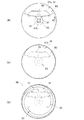
- FIG. 16A a first base cloth 31A and a second base cloth 41 before processing having a predetermined outer diameter are prepared.
- bent holes 34 are formed in the first base fabric 31A before processing.
- an inflator insertion hole 32 for inserting the inflator 20 and four bolt holes 33 for attaching the airbag 30 to the inflator 20 are formed.
- the first base cloth 31, the second base cloth 41, the vent hole cover 60, and the cover guide member 70 are made of a material (sheet) having a silicon coating only on one side.
- the first base cloth 31, the vent hole cover 60, and the cover guide member 70 are disposed so that the front surface and the back surface thereof face each other.
- the inner surface of the first base fabric 31 is the coating surface 31 a and the outer surface is the non-coating surface 31 b.
- the inner surface of the second base fabric 41 is a coating surface 41a, and the outer surface is a non-coating surface 41b.
- the airbag 30 is turned upside down from the inflator insertion hole 32 so that the outer seam 43 is located inside after the outer seam 43 is formed. Accordingly, in FIG. 16B, the first base cloth 31 is set so that the drawing surface side becomes the coating surface 31a, and the second base cloth 41 is set so that the drawing surface side becomes the non-coating surface 41b.
- the second reinforcing sheet 82 and the vent hole cover 60 are disposed on the coating surface 31a of the first base fabric 31.
- a first reinforcing sheet 81 is disposed on the non-coating surface 31 b (FIG. 3) of the first base fabric 31.
- the first and second reinforcing sheets 81 and 82 and the vent hole cover 60 are stitched to the first base cloth 31.
- the first and second reinforcing sheets 81 and 82 and the vent hole cover 60 are stitched so as to be the coating surfaces 81a, 82a, and 60a on the front side of the drawing.
- a cover guide member 70 is disposed on the coating surface 31 a of the first base fabric 31 so as to cover the vent hole cover 60, and a third reinforcing sheet 83 is provided on the cover guide member 70. Place.
- the coating surface 70a of the cover guide member 70 and the coating surface 83a of the third reinforcing sheet 83 are arranged so as to face the drawing front side.
- the airbag manufacturing method includes a first base cloth 31 having a vent hole 34, a vent hole cover 60, and Each of the cover guide members 70 is formed of a sheet of the same material having friction characteristics different from the front and back, and is arranged so that the front surface and the back surface of the sheet face each other between the members 31, 60, and 70. Thereby, the friction characteristic (slip characteristic) between each member 31,60,70 can be made uniform. As a result, it is possible to manufacture the airbag 30 whose deployment characteristics are within a predetermined range.
- the cover guide member 70 and the third reinforcing sheet 83 are stitched to the first base cloth 31.
- the cover guide member 70 is formed with guide stitching portions 73 to 75, and the guide stitching portions 73 to 75 are formed with stress concentration suppressing portions 76 and 76, respectively.
- the uncoated surface 31 b (see FIG. 3) of the first base fabric 31, which is stitched with the vent hole cover 60 and the cover guide member 70, is placed on the uncoated surface 41 b of the second base fabric 41. Is overlapped as shown by arrow a1.
- the coating surfaces 60a and 70a of the vent hole cover 60 and the cover guide member 70 are on the front side of the drawing.
- the uncoated surface 31b (see FIG. 3) of the first base fabric 31 to which the vent hole cover 60 and the cover guide member 70 are sewn is placed on the uncoated surface 41b of the second base fabric 41.
- the periphery of the first and second base fabrics 31 and 41 overlapped with each other is stitched as indicated by an arrow a2. Thereafter, the second base fabric 41 is pulled out from the inflator insertion hole 32 to the drawing front side.
- the first and second base cloths 31 and 41 are turned over.
- the vent hole cover 60, the cover guide member 70, and the stitched portion 43 (FIG. 3) on the outer periphery of the first and second base fabrics 31 and 41 are housed inside the airbag 30, and the first and second base fabrics 31. , 41 are exposed (FIG. 3). That is, the front and back of the base fabrics 31 and 41 are reversed.
- the first and second base fabrics 31, 41 are a plurality of strips and three stitches that are generally continuous in the circumferential direction from the center to the outer periphery. Suture (spiral sewing) is performed by 51, 52, 53. In the stitched portions 51, 52, and 53, a breakable suture 56 is used as shown in FIG. Both end portions of the vent hole cover 60 are stitched to the first and second base fabrics 31 and 41 by stitching portions 51, 52 and 53.
- the periphery of the two base fabrics 31 and 41 is sewn, and then the two base fabrics 31 and 41 are sewn with a breakable suture 56 (see FIG. 6). Therefore, after the vent hole cover 60 is fixed to the first base cloth 31, the end of the vent hole cover 60 is fixed. The portion can be fixed to the two base fabrics 31 and 41. As a result, the vent hole cover 60 is not easily displaced.
- the airbag manufacturing method of the present embodiment is a manufacturing method of an airbag formed by stitching two base fabrics 31, 41.
- a step of forming a vent hole 34 in one of the two base fabrics 31 and 41, a step of joining a vent hole cover 60 covering the vent hole 34 to the base fabric 31 having the vent hole 34 formed therein, and a formation of the vent hole 34 The step of joining the cover guide member 70 for restricting the movement of the vent hole cover 60 to the base fabric 31 and the step of joining the periphery of the two base fabrics 31 and 41 are included.
- a vent hole 34 is formed in one of the two base fabrics 31 and 41, and a vent hole cover 60 covering the vent hole 34 is stitched to the base fabric 31 in which the vent hole 34 is formed. Since the cover guide member 70 that restricts the movement of the vent hole cover 60 is sewn to the base cloth 31 in which the hole 34 is formed, and the periphery of the two base cloths 31 and 41 is sewn, one base cloth 31 side After all the functional parts such as the vent hole cover 60 and the cover guide member 70 are arranged, the two base cloths 31 and 41 can be sewn. Thereby, the handling at the time of manufacture of the airbag 30 becomes easy. As a result, the productivity of the airbag 30 can be improved.
- the step of sewing the vent hole cover 60 and the cover guide member 70 to the first base cloth 31 is different.
- the present invention is not limited to this, and the vent hole cover 60 and the cover guide member 70 may be sewn together in the same process. At this time, the vent hole cover 60 and the cover guide member 70 are preliminarily assembled.
- the guide member 70, the guide part 72, the opening part 77, etc. are not limited to the illustrated shape, and can be appropriately changed.
- the present invention is suitable for application to an automobile equipped with an airbag bag body that can be inflated and deployed between a passenger seated by introducing gas generated by an inflator and a passenger compartment.
Landscapes
- Engineering & Computer Science (AREA)
- Mechanical Engineering (AREA)
- Air Bags (AREA)
- Massaging Devices (AREA)
- Professional, Industrial, Or Sporting Protective Garments (AREA)
- Mattresses And Other Support Structures For Chairs And Beds (AREA)
Abstract
ベントホールに対するベントホールカバーの位置ずれを規制して、ベントホールからのガス放出を適正に行うことが可能なエアバッグが開示される。エアバッグ(30)は、ベントホールカバー(60)が所定のバッグ内圧でベントホール(34)を開放するように移動することを許容するカバーガイド部材(70)を備えている。カバーガイド部材は、ベントホールに対応する位置に形成された開口部(77)を有している。
Description
本発明は、インフレータにより発生したガスを導入することにより着座した乗員と車体との間に膨張展開可能なエアバッグに関する。
エアバッグのなかには、インフレータから導入されたガスでエアバッグを展開する際、エアバッグに設けたベントホールをベントホールカバーで覆うことでベントホールからのガス放出を規制するものがある。ベントホールカバーは、ベントホールに対して位置ずれしないように、ベントホールの近傍がカバーガイド部材で支えられている(例えば、特許文献1参照。)。
この特許文献1に開示されたエアバッグによれば、エアバッグが乗員を拘束可能な形状に展開するまでベントホールカバーでガスの放出を規制する。エアバッグが乗員を拘束可能な形状まで展開したとき、ベントホールカバーを止めていた縫糸が破断する。
縫糸が破断することで、縫糸によるベントホールカバーの保持が解放され、ベントホールカバーがベントホールからエアバッグの外側に押し出され、ベントホールカバーとベントホールとの間に形成された隙間からガスを外部に放出することで、エアバッグの内圧を調整することができる。
特許文献1のエアバッグは、ベントホールカバーがベントホールに対して位置ずれしないように、ベントホールの近傍がカバーガイド部材で支えられている。しかし、カバーガイド部材は、ベントホールに対応する部位(すなわち、ベントホールを塞いでいる部位)を支えていないため、ベントホールに対応する部位をベントホールからずれないように(位置ずれしないように)支えることは難しい。
このため、エアバッグが拘束可能な形状まで展開する前に、ベントホールからガスが外部に放出されてしまうことが考えられる。そこで、エアバッグを良好に展開させるために、インフレータのガス発生量をある程度増す必要があった。
本発明は、ベントホールに対するベントホールカバーの位置ずれを規制して、ベントホールからのガス放出を適正におこなうことが可能なエアバッグを提供することを課題とする。
本発明の一面によれば、エアバッグであって、インフレータと、前記インフレータから導入されたガスにより展開可能で、前記ガスを外部に放出可能なベントホールを備えたエアバッグと、から成り、前記エアバッグは、前記ベントホールを覆い、前記エアバッグに生じた所定の内圧で前記ベントホールを開放するように移動可能なベントホールカバーと、前記ベントホールカバーを覆い、前記ベントホールカバーが前記所定の内圧で前記ベントホールを開放するように移動することを許容するカバーガイド部材と、を備え、前記カバーガイド部材のうち、前記ベントホールに対応する部位に開口部が形成されているエアバッグが提供される。
好ましくは、前記ベントホールカバーは、前記インフレータに対応する部位から延出された延出部と、前記延出部の先端から該延出部に対して略直交する方向に延出された直交部と、を備え、前記延出部および前記直交部で略T字状に形成されるとともに、前記延出部および前記直交部が交差する交差部を前記ベントホールに対応するように形成し、前記カバーガイド部材は、前記交差部の両側に向けて前記直交部に対向するように延出されている。
好ましくは、前記カバーガイド部材は、該カバーガイド部材の先端から前記ベントホールまでの距離寸法を有し、該距離寸法は、前記カバーガイド部材の先端から前記ベントホールカバーの先端までの長さ寸法よりも大きくなるよう設定されている。
好ましくは、前記カバーガイド部材は、その先端が前記直交部に対して傾斜するように形成されている。
好ましくは、前記延出部は第1の側縁を有し、前記直交部は第2の側縁を有し、前記第1及び第2の側縁が交差するコーナ縁から前記ベントホールの周縁までの距離は、前記ベントホールカバーの他の部位から前記ベントホールの周縁までの距離よりも小さく設定されている。
好ましくは、前記コーナ縁は、前記カバーガイド部材の前記開口部の周縁に略一致している。
好ましくは、前記カバーガイド部材は、前記エアバッグの基布に縫合されるとともに、前記カバーガイド部材の縫合端への応力の集中を抑制する応力集中抑制部を前記縫合端の各々に有する。
好ましくは、前記応力集中抑制部の各々は、円弧状に形成されている。
本発明の別の面によれば、2枚の基布を接合することにより形成されるエアバッグの製造方法であって、前記2枚の基布の一方にべントホールを形成する工程と、前記ベントホールを形成した基布に前記ベントホールを覆うベントホールカバーを接合する工程と、前記ベントホールを形成した基布に前記ベントホールカバーの移動を規制するカバーガイド部材を接合する工程と、前記2枚の基布の周囲を接合する工程と、を含むエアバッグの製造方法が提供される。
好ましくは、前記方法は、前記2枚の基布の周囲を接合した後、前記2枚の基布を破断可能な縫合糸で縫合することにより、前記ベントホールカバーの端部を2枚の基布に固定する工程をさらに含む。
好ましくは、前記ベントホールを形成した基布、ベントホールカバー及びカバーガイド部材のそれぞれを表裏異なる摩擦特性を有する同材料のシートにより形成するとともに、前記各部材間で前記シートの表面と裏面とが対面するように配置する。
本発明のエアバッグ装置によるエアバッグは、ベントホールを覆うベントホールカバーを備えた。さらに、ベントホールカバーを覆うカバーガイド部材を備えた。よって、ベントホールに対するベントホールカバーの位置ずれをカバーガイド部材で規制することができる。これにより、エアバッグが拘束可能な形状まで展開する前にベントホールからガスが外部に放出されることを防ぐことができる。したがって、ベントホールからのガス放出を適正におこなうことが可能になり、エアバッグを良好に展開させることができる。
加えて、カバーガイド部材のうち、ベントホールに対応する部位に開口部を形成した。よって、ベントホールカバーに開口部を経てエアバッグの内圧を作用させることができる。これにより、エアバッグ袋体が所定の内圧まで上昇した際に、ベントホールを開放するようにベントホールカバーを所定の内圧で移動させることができる。したがって、ベントホールカバーとベントホールとの間に隙間が形成され、形成された隙間からガスを外部に放出することでエアバッグ袋体の内圧を適正に調整することができる。
上記エアバッグでは、ベントホールカバーを延出部および直交部で略T字状に形成し、延出部および直交部の交差部をベントホールに対応させた。そして、カバーガイド部材を、交差部の両側に向けて直交部に対向するように延出させた。よって、ベントホールに対応する交差部をカバーガイド部材で覆うとともに、交差部の両側をカバーガイド部材で覆うことができる。これにより、ベントホールに対するベントホールカバーの位置ずれを、カバーガイド部材で一層良好に規制することができる。
上記エアバッグでは、カバーガイド部材の先端からベントホールまでの距離寸法を、カバーガイド部材の先端からベントホールカバーの先端までの長さ寸法(すなわち、露出された部位の長さ寸法)より大きくした。よって、露出された部位が展開過程において開口部側に折り返された場合に、露出された部位が開口部まで到達して開口部に引き込まれることを防止できる。これにより、ベントホールを開放するようにベントホールカバーを確実に移動させることができる。
さらに、上記エアバッグでは、カバーガイド部材の先端を直交部に対して傾斜するように形成した。よって、展開過程において、露出された部位は、左右の先端で移動方向に対して傾斜した状態に折り返し方向が規制される。これにより、折り返された部位がカバーガイド部材の先端に当たった場合に、折り返された部位に発生する摩擦力を小さく抑えることができる。したがって、ベントホールを開放するようにベントホールカバーを円滑に移動させることができる。
本発明では、延出部の側縁および直交部の側縁が交差するコーナ縁からベントホールの周縁までの距離を、ベントホールカバーの他の部位からベントホール周縁までの距離よりも小さく設定した。よって、ベントホールカバーの他の部位とベントホールとの間に隙間を形成する際、コーナ縁とベントホールの間に隙間を良好に形成することができる。これにより、形成した隙間からガスを外部に良好に放出して、ベントホールカバーの変形を抑制するとともに、エアバッグの内圧を好適に調整することができる。
上記エアバッグでは、カバーガイド部材のうちベントホールに対応する部位に開口部を形成し、開口部の周縁をコーナ縁に略一致させた。よって、コーナ縁をカバーガイド部材で覆わないようにすることができる。これにより、コーナ縁とベントホールとの間に形成した隙間からガスを外部に良好に放出することができ、エアバッグの内圧を一層好適に調整することができる。
カバーガイド部材は、各縫合端に応力集中抑制部を有するので、カバーガイド部材がエアバッグの基布から剥離することを防止できる。
応力集中抑制部は円弧状に形成されているので、ガイド部材とベントホールカバーとの干渉を防ぐことができ、ベントホールカバーの円滑な移動を実現することができる。
本発明の別の面による方法では、一方の基布側にベントホールカバーやガイド部材などの機能部品を全て配置してから2枚の基布を接合することができる。これにより、エアバッグ袋体の製造時の取り扱いが容易になり、エアバッグの生産性の向上を図ることができる。
本発明方法は、ベントホールカバーを一方の基布に固定してからベントホールカバーの端部を2枚の基布に固定するため、ベントホールカバーに位置ずれが生じにくくなる。
ベントホールを形成した基布、ベントホールカバー及びガイド部材間でシートの摩擦特性が異なる表面と裏面とが対面するように配置するようにしたので、各部材間での摩擦特性(すべり特性)を均一にすることができる。この結果、展開特性を所定範囲内に納めたエアバッグを製造することができる。
以下、本発明の好ましい実施例について、添付した図面に基づいて説明する。
図1に示された車両10は、運転席11の前方に配置されたステアリングホイール12に車両用エアバッグ装置13が収納されている。エアバッグ装置13は、車両10に衝突エネルギーが作用した場合に、運転者の前側に展開して運転者(乗員)を拘束して保護する。
図2、図3および図4を参照するに、エアバッグ装置13は、高圧ガスを発生するインフレータ20と、インフレータ20で発生したガスが導入されるエアバッグ30と、エアバッグ30をステアリングホイール12(図1)に取り付けるリテーナ22および固定リング23とを備えている。
インフレータ20は、ステアリングホイール12にリテーナ22および固定リング23で取り付けられ、車両10(図1)に衝突エネルギーが作用したときに、高圧ガス(以下、「ガス」という)を発生し、発生したガスをエアバッグ30内に供給する。
リテーナ22をフランジ21と固定リング23とで挟持した状態で、インフレータ20の取付フランジ21に形成された取付孔、およびエアバッグ30内に配置される固定リング23の取付孔にボルト24を挿入して、該ボルト24をナットで締結することにより、インフレータ20は、ステアリングホイール12に固定される。リテーナ22はステアリングホイール12に設けられた部材である。
エアバッグ30は、外形が円形状に形成された第1基布31と、外形が円形状に形成された第2基布41と、第1基布31のベントホール34(後述する)を覆うベントホールカバー60と、ベントホールカバー60の位置ずれを抑えるカバーガイド部材70と、第1・第2・第3の補強シート81,82,83とを備えている。
エアバッグ30は、第1基布31および第2基布41が重ね合わせられ、それぞれの外周部42が接合される(外周の縫合部43で一体に縫製される)ことにより円形状のバッグ本体が形成され、インフレータ20からガスが導入されることで展開可能に構成されている。
第1基布31は、エアバッグ30が展開したとき、ステアリングホイール12(図1)に対向するように車体の前方向側に位置するシートである。この第1基布31は、インフレータ20を挿入するインフレータ挿入孔32と、インフレータ20を取り付ける複数のボルト孔33と、ガスを放出する(逃がす)ベントホール34とが形成されている。
インフレータ挿入孔32は、第1基布31の中心CPに同軸上に形成されている。インフレータ挿入孔32は、インフレータ20の先端部をエアバッグ30内に案内可能な円形状の貫通孔である。インフレータ20の先端部をエアバッグ30内に案内することで、インフレータ20で発生したガスがエアバッグ30の内部へ導入される。
複数のボルト孔33は、インフレータ挿入孔32の周囲に設けられ、ボルト24が挿通可能な貫通孔である。
ベントホール34は、例えば、展開したエアバッグ30のバッグ内圧(ガスによる内圧)を調整するために、エアバッグ30内に導入されたガスの一部を外部へ放出する円形状の貫通孔である。このベントホール34は、インフレータ挿入孔32の中心CPから所定距離だけオフセットした位置HP(ホール中心HP)に、配置されている。
第2基布41は、第1基布31と略同じ円形状に形成され、エアバッグ30が展開されたとき、乗員に対向するように車体の後方向側に位置するシートである。
エアバッグ30は、図3、図4に示すように、第1基布31の表面に第1補強シート81が重ね合わされ、第1基布31の裏面に第2補強シート82、ベントホールカバー60、カバーガイド部材70および第3補強シート83がこの順に重ね合わされ、それぞれの部材がインフレータ挿入孔32の周囲において一体となるように縫合されている。
第1・第2の基布31,41、ベントホールカバー60、カバーガイド部材70、および第1・第2・第3補強シート81,82,83は、全て同じ材質で、かつ同じ厚みの布(又は柔軟性を有したパネル)で形成されている。
これらの布は、表面(一方の面)と裏面(他方の面)とで、互いに異なる摩擦特性(摩擦抵抗)を有している。例えば、布の片面だけにシリコーンコーティングが施されることによって、表裏で摩擦特性が異なる。第1の基布31とベントホールカバー60、およびベントホールカバー60とカバーガイド部材70は、各々の表面と裏面とが互い違いに対面するように配置されている。
例えば、第1の基布31の摩擦抵抗は、裏面(第2の基布41と対向する面)の方が表面よりも大きい。第1の基布31の裏面(摩擦抵抗の小さい面)に、ベントホールカバー60の摩擦抵抗の小さい面が対向している。ベントホールカバー60の摩擦抵抗の大きい面に、カバーガイド部材70の摩擦抵抗の小さい面が対向している。
第1補強シート81、第2補強シート82、ベントホールカバー60、カバーガイド部材70および第3補強シート83は、第1基布31の複数のボルト孔33に対して同軸上にボルト孔がそれぞれ形成されている。一体的に縫合された第1補強シート81、第1基布31、第2補強シート82、ベントホールカバー60、カバーガイド部材70および第3補強シート83は、インフレータ20(具体的には、取付フランジ21)と固定リング23との間に挟み込まれている。この状態において、取付フランジ21のボルト孔および固定リング23のボルト孔が、第1基布31の複数のボルト孔33の各々に対して同軸上に配置されている。
ボルト孔33や他のボルト孔にボルト24を挿入してねじ結合することで、インフレータ20の取付フランジ21にエアバッグ30が取り付けられている。取付フランジ21がステアリングホイール12内のリテーナ22に取り付けられることで、エアバッグ30が取付フランジ21を介してリテーナ22に支持されている。
このエアバッグ30は、図2及び図5に示すように、第1基布31および第2基布41(図4)が重ね合わされた状態で、複数条、例えば3条の縫合部51,52,53で縫合されている。縫合部51,52,53は、インフレータ挿入孔32の中心CP寄りの各縫合始点54から外周部42の縫合終点55まで渦巻き状に縫合されている。
径方向内端に位置する縫合始点54は、エアバッグ袋体30の中心CPに向って延びている。よって、エアバッグ30のバッグ内圧によって、縫合始点54に応力を集中させることができる。
破断用縫合部51,52,53は、全て同じ構成であり、縫合始点54から縫合終点55までの長さが同一であって、互いに位相を120°ずらして配置されている。すなわち、破断用縫合部51,52,53は、インフレータ挿入孔32の中心CPから縫合始点54までの距離が全て同一であり、中心CPから縫合終点55までの距離も全て同一である。
図2において、インフレータ挿入孔32の中心CPを基準にして、ホール中心HPが位置する方位を0°とし、図時計回りに角度が大きくなるものとする。インフレータ挿入孔32の中心CPからホール中心HPの中心を通って方位0°に向けて延びる直線を基準線SL1とする。第1の基布31の面上において、基準線SL1に対し直交する直線を直交基準線SL2とする。
第1の破断用縫合部51は、方位0°を縫合始点54とし、この縫合始点54から径外方へ若干延びつつ周方向へ小さく円弧状に縫合され、その後に、図反時計回りに240°だけ渦巻き状に縫合されて、方位120°を縫合終点55とする。縫合始点54は、ベントホール34よりも径外方に位置する。縫合終点55は、基布31,41の外周縁に達する手前に形成され、これにより終点と、外周縁との間にガスが流入することが許容される。
同様に、第2の破断用縫合部52は、方位120°を縫合始点54とし、第1の破断用縫合部51の外周に沿いながら、図反時計回りに240°だけ渦巻き状に縫合され、方位240°を縫合終点55とする。
同様に、第3の破断用縫合部53は、方位240°を縫合始点54とし、第2の破断用縫合部52の外周に沿いながら、図反時計回りに240°だけ渦巻き状に縫合されて、方位0°を縫合終点55とする。
各破断用縫合部51,52,53は、径方向に所定の間隔を有して離間している。この間隔は、縫合始点54から縫合終点55へ進むにつれて徐々に狭くなる。
縫合部51,52,53は、エアバッグ30が展開する際に発生するバッグの内圧で各縫合始点54から外周側の各縫合終点55に向けて順次破断される。縫合部51,52,53が破断されることで、エアバッグ30の体積を大きくしてエアバッグ30の内圧を調整することが可能である。
図6に示すように、各破断用縫合部51,52,53は、両基布31,41の中央部寄りから外周部へ向けて、縫合糸56が順次破断されることによって、第1及び第2の基布31,41は分離する。
縫合糸56は、第1の糸56aと第2の糸56bとから成る。第1の糸56aは、所定以上のバッグ内圧によって破断されるように脆弱な糸、例えば引張強さ(引っ張って破断するのに要する力である破断荷重)が20Nから60Nの着色加工を施されていないフィラメント糸から成る。一方、第2の糸56bは、第1の糸56aを各破断用縫合部51,52,53の縫合方向へ案内する糸であって、エアバッグ袋体30の展開時にバッグ内圧によって破断されないように、引張強さが第1の糸56aよりも大きく設定されている。
このため、所定以上のバッグ内圧に基づき第1の糸に作用する張力によって、第1の糸56aが先に破断する。しかも、第1の糸56aは、第2の糸56bによって縫合方向に案内されている。このため、第1の糸56aは各破断用縫合部51~53におけるどの箇所においても破断強度が概ね一定に保たれる。従って、第1の糸56aは、第1及び第2の基布31,41における、中央部から外周部へ向けて、的確に順次破断される。
エアバッグ30は、インフレータ20から供給されたガスによって、よりタイミング良く且つ円滑に展開することができる。このため、バッグ内圧の変化を一層適切に制御することができる。インフレータ20からエアバッグ30にガスを供給開始した後における、エアバッグ30の内圧特性を、より一層的確なものにすることができる。
第1の糸56aは、連続した長繊維であるフィラメント糸(filament yarn)から成り、撚りが無い又はほぼ無いものである。撚りが無いので、糸の長さ方向に破断荷重のバラツキが少ない。従って、第1の糸56aは、所定以上のバッグ内圧によって、第1及び第2の基布31,41における、中央部から外周部へ向けて、的確に順次破断される。
図7及び図8に示すように、ベントホールカバー60は、ベントホール34を覆うことで、エアバッグ30のバッグ内圧が所定値に到達するまでベントホール34を塞ぐことが可能で、エアバッグ袋体30のバッグ内圧が所定値に到達したとき、バッグ内圧でベントホール34を開放するように移動可能なシート状のフラップである。
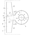
このベントホールカバー60は、第1基布31にボルト24…で取り付けられた環状のカバー基部61と、カバー基部61からベントホール34に向けて径方向に延出された縦帯状の延出部62と、延出部62の先端に設けられた横帯状の直交部63とからなる。ベントホールカバー60は、延出部62および直交部63で略T字状に形成され、延出部62および直交部63の交差部66がベントホール34に対応するように形成されている。ベントホールカバー60は、図2に示す基準線SL1に対して左右対称に形成されている。
カバー基部61は、インフレータ挿入孔32(図4も参照)の中心CPに同軸上に設けられた環状の部位であり、インフレータ挿入孔32に対して同軸上で、かつ、略同径の貫通孔67を有している。このカバー基部61は、インフレータ挿入孔32の周囲において、第1基布31に縫合されている。
延出部62は、第1基布31の裏面に沿わせて、カバー基部61(すなわち、図4に示すインフレータ20側)からベントホール34に向けて所定幅で延出された縦帯状の部位である。
直交部63は、第1基布31の裏面に沿わせて、延出部62の先端62aから延出部62に対して略直交する方向(すなわち、左右両方)に延出された横帯状の部位である。この直交部63は、延出部62の上方に設けられた交差部66と、交差部66から左方向に略水平に延出された左帯状部64と、交差部66から右方向に略水平に延出された右帯状部64とを備えている。
交差部66および左右の帯状部64の各上縁66a,64b,64bは、同一水平線上に連続的に延出されている。すなわち、直交部63の上縁は、図2に示す直交基準線SL2に対して略平行に形成されている。
左帯状部64の下縁64cは、交差部66から左先端に向けて上り勾配でテーパ状に延出されている。右帯状部64の下縁64cは、交差部66から右先端に向けて上り勾配でテーパ状に延出されている。
左帯状部64の先端64dは、エアバッグ30の縫合部43に沿って傾斜状に形成されている。右帯状部64の先端64dは、エアバッグ30の縫合部43に沿って傾斜状に形成されている。
左右の帯状部64,64の先端部(すなわち、直交部63の両端部)64a,64aは、カバーガイド部材70から露出し、破断可能な縫合部51,52,53で第1・第2の基布31,41に縫合されている。すなわち、左右の帯状部64,64の先端部64a,64aは、「露出された部位」である。
図9に示すように、延出部62の左側縁62bおよび左帯状部64の下縁64cが交差する部位に凹状の左コーナ縁68が形成されている。左コーナ縁68からベントホール34の周縁34aまでの左コーナ距離がL1に設定されている。
延出部62の右側縁62bおよび右帯状部64の下縁64cが交差する部位に凹状の右コーナ縁69が形成されている。右コーナ縁69からベントホール34の周縁34aまでの右コーナ距離が、左コーナ距離と同様に、L1に設定されている。
さらに、交差部66の上縁(ベントホールカバー60の他の部位)66aからベントホール34の周縁34aまでの上縁距離がL2に設定されている。左コーナ距離L1および右コーナ距離L1は、上縁距離L2より小さく設定されている。
左コーナ縁68および右コーナ縁69は延出部62で支えられている。よって、エアバッグ30のバッグ内圧で左コーナ縁68および右コーナ縁69をベントホール34に引き込む際に、左コーナ縁68や右コーナ縁69の引込みが延出部62で妨げられることが考えられる。
左コーナ縁68や右コーナ縁69の引込みが妨げられると、交差部66の全域をベントホール34に均等に引き込むことが難しい。このため、ベントホールカバー60の形状が不安定となり、ベントホールカバー60とベントホール34との間の隙間からのガスの流出量を安定化することができないおそれがある。
そこで、左コーナ距離L1および右コーナ距離L1を上縁距離L2より小さく設定した。よって、交差部66の上縁66aとベントホール34との間に隙間を形成する際に、左コーナ縁68とベントホール34との間に隙間を良好に形成するとともに、右コーナ縁69とベントホール34との間に隙間を良好に形成することができる。これにより、交差部60の変形を抑制して形成した隙間からガスを外部に良好に放出して、エアバッグ30の内バッグ圧を好適に調整することができる。
再度、図7及び図8を参照すると、カバーガイド部材70は、ベントホールカバー60の交差部66がベントホール34に対して位置ずれすることを規制するために被カバー部位85を覆い、ベントホールカバー60がベントホール34を開放するように移動することを許容するシートである。
ベントホールカバー60の被カバー部位85は、ベントホールカバー60から左帯状部64の先端部(露出された部位)64aおよび右帯状部64の先端部(露出された部位)64aを除いた部位であり、略中央にベントホール34に対応する部位(以下、「ホール閉部位」という)86が含まれている。ホール閉部位86は、交差部66に形成されている。
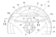
被カバー部位85を覆うカバーガイド部材70は、第1基布31にボルト孔33(図4)を介してボルト24で取り付けられた環状のガイド基部71と、ガイド基部71の上端に設けられた横帯状のガイド部72とからなる。カバーガイド部材70は、図2に示す基準線SL1に対して左右対称に形成されている。
ガイド基部71は、ベントホールカバー60のカバー基部61と同様に、インフレータ挿入孔32(図4も参照)の中心CPに同軸上に設けられた環状の部位であり、インフレータ挿入孔32に対して同軸上で、かつ、略同径の貫通孔87を備えている。このガイド基部71は、インフレータ挿入孔32の周囲において、第1基布31に一体に縫合されている。
ガイド基部71をインフレータ挿入孔32の周囲を縫合することで、インフレータ20の近傍までガイド基部71を延長できる。これにより、インフレータ20とカバーガイド部材70との相対位置の調整が容易となり製造精度が向上する。
ガイド部72は、ガイド基部71における上端71aから、第1基布31の裏面に沿わせて、左右方向に延出された横帯状の部位である。このガイド部72は、ベントホールカバー60の直交部63に重ね合わされ、上辺部72bが第1縫合部73で第1基布31に縫合され、左下辺部72cが第2縫合部74で第1基布31に縫合され、右下辺部72dが第3縫合部75で第1基布31に縫合されている。ガイド部72は、破断用縫合部51~53(図2)近傍まで延出配置され、左右の先端72a,72aが第1基布31に縫合されることなく開放されている。
第1縫合部73の左側部位と第2縫合部74との間に左帯状部64が配置され、左帯状部64の先端部(露出された部位)64aが左先端72aからガイド部72の外部に突出されている。第1縫合部73の右側部位73aと第3縫合部74との間に右帯状部64が配置され、右帯状部64の先端部(露出された部位)64aが右先端72aからガイド部72の外部に突出されている。
すなわち、ガイド部72は、交差部66の左右側(両側)に向けて直交部63(左右の帯状部64)に対向するように延出されている。ガイド部72は、ホール閉部位86に対応する部位88に開口部77が円形状に形成されている。
開口部77の周縁77aは、凹状の左コーナ縁68および凹状の右コーナ縁69に略一致している(図7)。よって、凹状の左コーナ縁68および凹状の右コーナ縁69をカバーガイド部材70で覆わないようにすることができる。開口部77は、ベントホール34と同軸上に形成されている。
第1・第2・第3の縫合部73,74,75は、ベントホールカバー60の直交部63が移動(摺動)する方向を規制するガイド部である。よって、ベントホールカバー60の直交部63が移動(摺動)するとき、ガイド用の3つの縫合部73,74,75で直交部63が案内されるとともに、直交部63の移動方向が規制される。
第1縫合部73は、ガイド部72の上辺部72bに沿って左先端72a近傍から右先端72a近傍まで縫合されている。換言すれば、第1縫合部73は、ガイド部72の上縁に略平行に縫合されている。
第2縫合部74は、ガイド部72の左下辺部72cに沿って左先端72a近傍から延出部62の左側縁62b(図9)近傍まで縫合されている。換言すれば、第2縫合部74は、左先端72a近傍から左側縁62b近傍までインフレータ挿入孔32に近づくよう下り勾配に傾斜するように縫合されている。
第3縫合部75は、ガイド部72の右下辺部72dに沿って右先端72a近傍から延出部62の右側縁62b近傍まで縫合されている。換言すれば、第3縫合部75は、右先端72a近傍から右側縁62b近傍までインフレータ挿入孔32に近づくよう下り勾配に傾斜するように縫合されている。
第1~第3の縫合部73~75は、両側の縫合端に応力集中抑制部76,76をそれぞれ有している。第1縫合部73の応力集中抑制部76,76は、第1縫合部73の上側に形成されている。第2・第3縫合部74,75の各応力集中抑制部76,76は、第2・第3ガイド用縫合部74,75の下側にそれぞれ形成されている。
第1~第3の縫合部73~75の応力集中抑制部76,76は、ベントホールカバー60から遠ざかる方向にループ状に縫合されている。本実施例においては、応力集中抑制部76,76は、第1~第3の縫合部73~75に沿うように略長円形即ち、湾曲状に形成されている。これにより、第1~第3の縫合部73~75が各応力集中抑制部76,76から破断することを防止でき、ベントホールカバー60を円滑に移動(摺動)させることができる。
このように、カバーガイド部材70のガイド部72を直交部63(左右の帯状部64)に対向するように延出し、上辺部72bが第1縫合部73で第1基布31に縫合され、左右の下辺部72c,72dが第2、第3の縫合部74,75で第1基布31に縫合されている。よって、ベントホールカバー60の被カバー部位85がベントホール34に対して位置ずれすることをカバーガイド部材70で規制することができる。
特に、ベントホール34に対応する交差部66(詳しくは、交差部66のうち、開口部77に相当する箇所を除いた部位)をカバーガイド部材70で覆うことができる。よって、ベントホール34に対するベントホールカバー60の位置ずれを、カバーガイド部材70で確実に規制することができる。
さらに、カバーガイド部材70のうちホール閉部位86に対応する部位に開口部77を形成した。よって、ホール閉部位86に開口部77を経てエアバッグ30のバッグ内圧を作用させることができる。これにより、バッグ内圧が所定の内圧まで上昇した際に、ベントホール34を開放するようにベントホールカバー60の直交部63をバッグ内圧で移動させることができる。したがって、ベントホールカバー60がベントホール34内に押し込まれ、ベントホール34周辺のベントホールカバー60が波打った皺状態になり、該ベントホールカバー60と第1基布31との間に隙間が形成され、該隙間はベントホール34に連通する。このように隙間を介してベントホールからガスが外部に放出することでエアバッグ30の内圧を適正に調整することができる。
ガイド部72は、ガイド部72の左先端72aからベントホール34までの左距離寸法がL3に設定され、ガイド部72の右先端72aからベントホール34までの距離寸法がL3に設定されている。
一方、ベントホールカバー60は、ガイド部72の左先端72aから左帯状部64の先端64dまでの露出された部位(すなわち、先端部)64aの左長さ寸法がL4に設定され、ガイド部72の右先端72aから右帯状部64の先端64dまでの露出された部位(すなわち、先端部)64aの右長さ寸法がL4に設定されている。
左距離寸法L3が左長さ寸法L4より大きく設定され、右距離寸法L3が右長さ寸法L4より大きく設定されている。左帯状部64の露出された部位(すなわち、先端部)64aが開口部77側に折り返された場合に、折り返された先端部64aが開口部77まで到達して開口部77に引き込まれることを防止できる。なお、右側についても同様である。これにより、ベントホールカバー60を確実に移動させて、ベントホール34を開放することができる。
さらに、ガイド部72は、ガイド部72の左右の先端72aがベントホールカバー60の直交部63に対してそれぞれ傾斜するように形成されている。左帯状部64の露出された部位(すなわち、先端部)64aは、左先端72aで移動方向に対して傾斜した状態に折り返される。なお、右側についても同様である。これにより、左側の折り返された部位が左先端72aに当たった場合に、左側の折り返された部位に発生する摩擦力を小さく抑えることができる。なお、右側についても同様である。したがって、ベントホール34を開放するようにベントホールカバー60を円滑に移動させることができる。
次に、車両用エアバッグ装置13のエアバッグ30を展開する例を図10~図13に基づいて説明する。
図10において、車両10(図1)に所定値を超えた衝突エネルギーが作用した場合、インフレータ20からエアバッグ30内にガスが矢印Aの如く導入される。エアバッグ30内にガスが導入されることでエアバッグ30が展開を開始する。
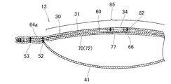
図11において、エアバッグ30は第1・第2の基布31,41同士が破断可能な縫合部51~53(縫合部52は図10参照)で一体に縫合されている。よって、ベントホールカバー60の左右側の先端部64a,64a(右側の先端部64aは図10参照)は、縫合部51~53で第1・第2の基布31,41に拘束されている。
ベントホールカバー60の被カバー部位85がベントホール34に対して位置ずれすることをカバーガイド部材70で規制している。特に、ベントホール34に対応する交差部66(詳しくは、交差部66のうち、開口部77に相当する箇所を除いた部位)がカバーガイド部材70で覆われている。
このように、第1基布31および第2基布41が縫合部51~53で縫合され、かつ、ベントホール34からガスが外部に放出することを防ぐことで、エアバッグ30は展開初期にその膨張容積を規制される。よって、エアバッグ30は、中央部や縫合部51~53間の規制された容積内で速やかに一様な膜圧分布に達する。
この時点で、乗員がステアリングホイール12(図1)に近接した位置に存在し、エアバッグ30に接触開始する場合には、バッグ内圧の上昇とともに縫合部51~53の破断が進行することにより、バッグ内圧上昇量が抑制されて柔らかく乗員を拘束することができる。
一方、エアバッグ30に乗員が接触しない場合にも、インフレータ20からのガス導入によるバッグ内圧の増加に応じて、縫合部51~53が縫合始点54から縫合終点55へ向かって順次破断される。このため、エアバッグ30は、適切なバッグ内圧を維持しながら、次第に容積を増加し、所定の形状となるように展開する。
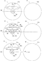
図12A及び図12Bは、エアバッグ30が展開した状態を示している。図12Aにおいて、縫合部51~53(図10)が破断されることで、エアバッグ30のバッグ内圧を好適に保ちながらエアバッグ30を所定の形状に展開することができる。
縫合部51~53が破断すると、ベントホールカバー60の左右側の先端部64a,64aの拘束が解除される。一方、エアバッグ30のバッグ内圧が、カバーガイド部材70の開口77を経てベントホールカバー60のホール閉部位86に矢印Bの如く作用する。よって、縫合部51~53が破断して左右側の先端部64a,64aの拘束が解除されることで、ベントホールカバー60の左右の帯状部64,64が矢印Cの如く移動する(引き込まれる)。
図12Bにおいて、左右の帯状部64,64が矢印Cの如く移動する(引き込まれる)ことで、ホール閉部位86がベントホール34からエアバッグ30の外部へ押し出される。
図9に示すように、左コーナ距離L1および右コーナ距離L1は、上縁距離L2よりも小さく設定されている。よって、交差部66の上縁66aとベントホール34との間に隙間を形成する際に、交差部66の変形を抑制して左コーナ縁68とベントホール34との間に隙間を良好に形成するとともに、右コーナ縁69とベントホール34との間に隙間を良好に形成することができる。
さらに、図7に示すように、開口部77の周縁77aは、凹状の左コーナ縁68や凹状の右コーナ縁69に略一致している。よって、凹状の左コーナ縁68および凹状の右コーナ縁69をカバーガイド部材70で覆わないようにすることができる。
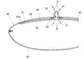
図13は、エアバッグ30のベントホール34からガスが外部に放出する例を示している。
図12Bで説明したように、左右のコーナ縁68,69とベントホール34との間に隙間を良好に形成し、かつ、左右のコーナ縁68,69をカバーガイド部材70で覆わないようにした。これにより、左右のコーナ縁68,69とベントホール34との間の隙間から、エアバッグ30内の余剰ガスを図11に示すように外部に矢印Dの如く良好に放出することができる。余剰ガスを外部に良好に放出することで、エアバッグ30が最大形状となった後でもエアバッグ30のバッグ内圧の過剰な上昇を防止して、バッグ内圧を好適に調整することができる。
図12Aで説明したように、左右の帯状部64,64が矢印Cの如く移動する(引き込まれる)際に、左右の帯状部64,64の先端部(露出された部位)64a,64aが折り返されることが考えられるが、前述の通り先端部64aが開口部77側に折り返された場合に、折り返された先端部64aが開口部77まで到達して開口部77に引き込まれることを防止でき、かつ先端部64aがカバーガイド部材70の先端72aに当たった場合に発生する摩擦力を小さく抑えることができるので、ベントホール34を開放するようにベントホールカバー60を円滑に移動させることができる。
図14(a),(b)は、図8に示したカバーガイド部材の応力集中抑制部を示している。第1~第3のガイド用縫合部73~75は、それぞれ両側の縫合端に応力集中抑制部76,76を有している。
図7及び図14(a),(b)に示すように、応力集中抑制部76,76は、ガイド用縫合部73~75の各縫合端において、ベントホールカバー60から遠ざかる方向に更にループ状に縫合した部分である。本実施例においては、応力集中抑制部76,76は、それぞれのガイド用縫合部73~75に沿う方向に細長い正面視略長円形に形成されている。このため、それぞれの縫合端は円弧状を呈する。
図14(a)に示されるように、第1のガイド用縫合部73を例にして説明すれば、応力集中抑制部76は、本縫合部73aの端部にベントホールカバー60から離間する方向に向けて半円弧状に縫合した第1円弧部76aと、この第1円弧部76aから直線状に縫合した第1直線部76bと、この第1直線部76bからベントホールカバー60に接近する方向に向けて半円弧状に縫合した第2円弧部76cと、この第2円弧部76cから直線状に且つ本縫合部73aに沿うよう縫合した第2直線部76dとからなる。
第2及び第3のガイド用縫合部74,75に形成される応力集中抑制部76も、図14(b)に示すように第1のガイド用縫合部73の応力集中抑制部76と同様である。第2及び第3のガイド用縫合部74,75も、それぞれ本縫合部74a,75aを有する。
図15(a)は、本実施例と比較するために応力集中抑制部を有していないカバーガイド部材を示しており、図15(b)は、応力集中抑制部を有している本実施例のカバーガイド部材を示している。
図15(a)に示したエアバッグ300は、ベントホール309をカバーするベントホールカバー301が設けられ、このベントホールカバー301をガイドするカバーガイド部材302が設けられている。このカバーガイド部材302は、エアバッグ袋体300の基布(図示せず)に第1~第3のガイド用縫合部303~305で縫合されている。
第1~第3のガイド用縫合部303~305は直線状に形成されているので、インフレータ(図示せず)によるガスにより、ベントホールカバー301がカバーガイド部材302に対して移動するときに、例えば、第1のガイド用縫合部303の縫合端部306や第2のガイド用縫合部304の縫合端部307,307に剪断応力が作用し、カバーガイド部材302がエアバッグ300の基布から剥離するおそれがある。
さらに、第1のガイド用縫合部303の縫合端部306や第2のガイド用縫合部304の縫合端部307,307は、カバーガイド部材302に対して点接触に近似するかたちで縫製されているので、カバーガイド部材302にベントホールカバー301が食い込む力が作用することもあり、ベントホールカバー301の円滑な移動が阻害される可能性がある。
図15(b)において、本実施例のエアバッグ30は、図2及び図3に示されているように、インフレータ20のガスにより展開され、内圧の上昇を防止するベントホール34を備えている。エアバッグ30は、ベントホール34を覆うベントホールカバー60と、このベントホールカバー60の移動を規制する若しくはガイドするカバーガイド部材70とを備える。
カバーガイド部材70は、エアバッグ30の第1の基布31に縫合され、カバーガイド部材70の縫合端への応力の集中を抑制する複数の応力集中抑制部76を形成したので、エアバッグ30の第1の基布31から剥離されない。
応力集中抑制部76は円弧状に形成されているので、カバーガイド部材70とベントホールカバー60との干渉を防ぐことができ、ベントホールカバー60の円滑な移動を実現することができる。
図7に示すように、第1~第3のガイド用縫合部73~75に対して、応力集中抑制部76,76は次の関係にある。つまり、第1のガイド用縫合部73の応力集中抑制部76,76は、第1のガイド用縫合部73よりも上に形成されている。第2及び第3のガイド用縫合部74,75の応力集中抑制部76,76は、第2及び第3のガイド用縫合部74,75よりも下に形成されている。
このように、応力集中抑制部76,76は、第1~第3のガイド用縫合部73~75の縫合端に設けられている。ベントホールカバー60が第1・第2ガイド用縫合部73,74間を移動するときや、ベントホールカバー60が第1・第3ガイド用縫合部73,75間を移動するときに、ベントホールカバー60の縁は、応力集中抑制部76,76に接触しながら移動する。これらの応力集中抑制部76,76は円弧状に形成されているので、この部分に応力が集中することが抑制される。このため、ガイド用縫合部73~75における各縫合端が、ベントホールカバー60に擦られて損傷する心配はない。また、ベントホールカバー60とカバーガイド部材70とが干渉し合うこともない。従って、ベントホールカバー60は円滑に移動することができる。
基準線SL1からガイド部72の先端72aまでの長さは、基準線SL1から帯状部64の先端部64aまでの長さよりも、短く設定されている。しかし、基準線SL1からガイド部72の先端72aまでの長さは、この先端72aから帯状部64の先端部64aまでの長さよりも、長く設定されている。従って、破断用縫合部51~53が破断して先端部64aの拘束が解かれ、帯状部64が基準線SL1側へ移動する途中において、帯状部64がガイド部72側へ折り返ったとしても、先端部64aによってベントホール34が塞がれることはない。
ガイド部72における左右の先端72a,72aは、基準線SL1に対して傾斜した(ベントホールカバー60の直交部63に対して傾斜した)傾斜状に形成されている。従って、ベントホールカバー60の帯状部64が基準線SL1側へ移動する途中において、帯状部64がガイド部72側へ折り返ったとしても、傾斜した先端72aに沿って、斜めに折り返ることになる。このため、帯状部64は折り返し状態が極めて容易に解消される。帯状部64はガイド部72内を円滑に移動することができる。
ガイド部72は、ホール中心HP(図2)に位置する開口部77を有する。つまり、ガイド部72の開口部77は、ベントホール34に対応する部位に形成されている。この開口部77は、ベントホール34と略同型の円形孔である。
次に、エアバッグ装置13の作用を説明する。
車両10(図1参照)に所定以上の衝突エネルギーが作用したしたときに、図3に示すインフレータ20はガスを発生させて、エアバッグ30にガスを供給する。ステアリングホイール12(図1)に折り畳み状態で収納されているエアバッグ30は、ガスによって展開を開始する。エアバッグ30が展開する過程において、ステアリングホイール12に取付けられたカバー(図示せず)が、ティアラインから破断してエアバッグ30が展開するための開口を形成する。この結果、エアバッグ30は車室内に展開し始める。
車両10(図1参照)に所定以上の衝突エネルギーが作用したしたときに、図3に示すインフレータ20はガスを発生させて、エアバッグ30にガスを供給する。ステアリングホイール12(図1)に折り畳み状態で収納されているエアバッグ30は、ガスによって展開を開始する。エアバッグ30が展開する過程において、ステアリングホイール12に取付けられたカバー(図示せず)が、ティアラインから破断してエアバッグ30が展開するための開口を形成する。この結果、エアバッグ30は車室内に展開し始める。
図2及び図3に示すように、エアバッグ30は第1及び第2の基布31,41同士が3つの破断用縫合部51~53によって縫合されている。このため、エアバッグ30は展開初期にその膨張容積が規制され、中心と破断用縫合部51~53間の規制された容積内で速やかに一様な膜圧分布に達する。この時点で乗員がステアリングホイール12に近接した位置に存在し、接触開始するときには、内圧の上昇とともに破断用縫合部51~53の破断が進行することにより内圧上昇量が抑制され、柔らかく乗員を拘束することができる。
乗員との接触がないときにも、インフレータ20からのガス流入によるエアバッグ30におけるバッグ内圧の増加に応じて、3つの破断用縫合部51~53は、縫合始点54から縫合終点55へ向かって順次破断される。このため、エアバッグ30は、適切なバッグ内圧を維持しながら、次第に容積を増加し、所定の形状となるように展開する。
図7に示すように、ベントホールカバー60における左右の帯状部64,64の先端部64a,64aは、各破断用縫合部51~53によって、第1・第2の基布31,41に縫合されている。このため、各破断用縫合部51~53が破断するまでは、先端部64a,64aが第1・第2の基布31,41に拘束されている。ベントホール34が、ベントホールカバー60により閉鎖されているので、エアバッグ30内のガスは外部へ逃げることを阻止されている。この結果、エアバッグ30内のガス圧は速やかに上昇し、そのガス圧が適切に保持される。エアバッグ30内のガス圧は、カバーガイド部材70の開口部77を通して、ベントホールカバー60の直交部63における中央部に作用する。
その後、エアバッグ30の展開末期に、全ての破断用縫合部51~53が破断すると、帯状部64,64の先端部64a,64aの拘束が解かれる。ベントホールカバー60の直交部63における中央部は、ベントホール34から外部へ押し出される。押し出されるにつれて、左右の帯状部64,64はガイド部72に案内されて(ガイド用縫合部73~75に案内されて)、ベントホール34へ向かって移動する。この結果、ベントホール34が開放される。このように各破断用縫合部による圧力上昇の緩和が終了した後にも、エアバッグ30内の余剰のガスがベントホール34から排出されるので、エアバッグ30は最大形状となった後もエアバッグ30のバッグ内圧の過剰な上昇を防止される。
本実施例によるエアバッグは、図14(a),(b)に示すように、応力集中抑制部76が、第1円弧部76aと、第1直線部76bと、第2円弧部76cと、第2直線部76dとからなるループ状に形成された例を示しているが、これに限るものではなく、楕円、円弧若しくは曲線を含む縫製端部が丸まっている縫製を含むものであってもよい。
次に、エアバッグの製造方法について、図16、図17および図18に基づいて説明する。
図16(a)において、所定の外径を有する加工前の第1の基布31A及び第2の基布41を用意する。
図16(b)において、加工前の第1の基布31Aにべントホール34を形成する。同時に、インフレータ20を挿入するインフレータ挿入孔32と、インフレータ20にエアバッグ30を取付ける4個のボルト孔33とを形成する。
先に説明したように、第1の基布31、第2の基布41、ベントホールカバー60及びカバーガイド部材70は、片面だけにシリコンコーティングが施された素材(シート)が用いられる。第1の基布31、ベントホールカバー60及びカバーガイド部材70は、各々の表面と裏面とが対面するように配置される。エアバッグ30の完成品において、第1の基布31の内面がコーティング面31aであり、外面が非コーティング面31bである。第2の基布41の内面がコーティング面41aであり、外面が非コーティング面41bである。エアバッグ30は、外周の縫合部43が形成された後に、インフレータ挿入孔32から外周の縫合部43が内部に位置するように裏返す。従って、図16(b)において、第1の基布31は図面表側がコーティング面31aとなるようセットし、第2の基布41は図面表側が非コーティング面41bとなるようセットする。
図16(c)において、第1の基布31のコーティング面31aに第2補強シート82及びベントホールカバー60を配置する。第1の基布31の非コーティング面31b(図3)に第1補強シート81を配置する。第1の基布31に第1・第2補強シート81,82及びベントホールカバー60を縫合する。第1・第2補強シート81,82及びベントホールカバー60は、図面表側にコーティング面81a,82a,60aとなるように縫合される。
図17(a)において、第1の基布31のコーティング面31aに、且つベントホールカバー60を覆うようにカバーガイド部材70を配置し、このカバーガイド部材70の上に第3の補強シート83を配置する。カバーガイド部材70のコーティング面70a及び第3補強シート83のコーティング面83aが図面表側に向くよう配置される。
エアバッグの製造方法は、図16(b)、図16(c)及び図17(a)に示されているように、ベントホール34を形成した第1の基布31、ベントホールカバー60及びカバーガイド部材70のそれぞれを表裏異なる摩擦特性を有する同材料のシートにより形成し、各部材31,60,70間でシートの表面と裏面とが対向するように配置している。これにより、各部材31,60,70間での摩擦特性(すべり特性)を均一にすることができる。この結果、展開特性を所定範囲内に納めたエアバッグ30を製造することができる。
図17(b)において、第1の基布31にカバーガイド部材70及び第3補強シート83が縫合される。カバーガイド部材70には、ガイド用縫合部73~75が形成され、ガイド用縫合部73~75には、それぞれ応力集中抑制部76,76が形成される。
図17(c)において、ベントホールカバー60及びカバーガイド部材70を縫合した第1の基布31の非コーティング面31b(図3参照)を、第2の基布41の非コーティング面41bの上に矢印a1のごとく重ねる。ベントホールカバー60およびカバーガイド部材70のコーティング面60a,70aは、図面表側になる。
図18(a)において、ベントホールカバー60及びカバーガイド部材70を縫合した第1の基布31の非コーティング面31b(図3参照)を、第2の基布41の非コーティング面41bの上に重ねた第1・第2の基布31,41の周囲を矢印a2の如く縫合する。その後、第2の基布41をインフレータ挿入孔32から図面表側に引き出す。
図18(b)において、インフレータ挿入孔32から第2の基布41を紙面表側に引き出した結果、第1・第2の基布31,41が裏返される。ベントホールカバー60、カバーガイド部材70及び第1・第2の基布31,41の外周の縫合部43(図3)はエアバッグ30の内部に収納され、第1・第2の基布31,41の非コーティング面31b,41bは露呈される(図3)。すなわち、基布31,41の表裏は反転される。
図18(c)において、第1及び第2の基布31,41(31は図3参照)は、中央部から外周部へ向けて概ね円周方向に連続する複数条、3条の縫合部51,52,53により縫合(スパイラル縫製)される。縫合部51,52,53では、図6に示されているように、破断可能な縫合糸56が使用されている。ベントホールカバー60の両端部は、縫合部51,52,53により第1・第2の基布31,41に縫合される。
本実施例のエアバッグの製造方法では、2枚の基布31,41の周囲を縫合した後、2枚の基布31,41を破断可能な縫合糸56(図6参照)で縫合することにより、ベントホールカバー60の端部を2枚の基布31,41に固定する工程を備えているので、ベントホールカバー60を第1の基布31に固定した後、ベントホールカバー60の端部を2枚の基布31,41に固定することができる。この結果、ベントホールカバー60に、位置ずれが生じにくい。
図3、図16~図18で説明したように、本実施例のエアバッグの製造方法は、2枚の基布31,41を縫合することにより形成されるエアバッグの製造方法であって、2枚の基布31,41の一方にべントホール34を形成する工程と、ベントホール34を形成した基布31にベントホール34を覆うベントホールカバー60を接合する工程と、ベントホール34を形成した基布31にベントホールカバー60の移動を規制するカバーガイド部材70を接合する工程と、2枚の基布31,41の周囲を接合する工程とを含む。
エアバッグの製造方法では、2枚の基布31,41の一方にべントホール34を形成し、このベントホール34を形成した基布31にベントホール34を覆うベントホールカバー60を縫合し、ベントホール34を形成した基布31にベントホールカバー60の移動を規制するカバーガイド部材70を縫合し、2枚の基布31,41の周囲を縫合するようにしたので、一方の基布31側にベントホールカバー60やカバーガイド部材70などの機能部品を全て配置してから2枚の基布31,41を縫合できる。これにより、エアバッグ30の製造時の取り扱いが容易になる。この結果、エアバッグ30の生産性の向上を図ることができる。
本実施例によるエアバッグの製造方法では、図16(c)及び図17(b)で説明したように、第1の基布31にベントホールカバー60及びカバーガイド部材70を縫合する工程が別工程の例を示したが、これに限るものではなく、ベントホールカバー60及びカバーガイド部材70を同一工程で一緒に縫合するようにしてもよい。この時、ベントホールカバー60およびカバーガイド部材70は事前に仮組み状態としておく。
本実施例で示したベントホール34、ベントホールカバー60、延出部62、直交部63、左右の帯状部64、交差部66、交差部の上縁66a、左右のコーナ縁68,69、カバーガイド部材70、ガイド部72、開口部77などは、例示した形状に限定するものではなく適宜変更が可能である。
本発明は、インフレータにより発生したガスを導入することにより着座した乗員と車室との間に膨張展開可能なエアバッグ袋体を備えた自動車への適用に好適である。
10…車両、13…車両用エアバッグ装置、20…インフレータ、30…エアバッグ袋体、34…ベントホール、60…ベントホールカバー、62…延出部、62a…延出部の先端、63…直交部、64…左右の帯状部、64d…左右の帯状部の先端、66…交差部、70…カバーガイド部材、72…ガイド部、72a…カバーガイド部材の左右の先端(先端)、77…開口部、86…ホール閉部位(ベントホールに対応する部位)、L3…左右の距離寸法(距離寸法)、L4…左右の長さ寸法(長さ寸法)。
Claims (11)
- インフレータから導入されたガスにより展開可能で、前記ガスを外部に放出可能なベントホールを備えたエアバッグであって、
前記ベントホールを覆い、前記エアバッグに生じた所定の内圧で前記ベントホールを開放するように移動可能なベントホールカバーと、
前記ベントホールカバーを覆い、前記ベントホールカバーが前記所定の内圧で前記ベントホールを開放するように移動することを許容するカバーガイド部材と、を備え、
前記カバーガイド部材のうち、前記ベントホールに対応する部位に開口部が形成されているエアバッグ。 - 前記ベントホールカバーは、
前記インフレータに対応する部位から延出された延出部と、
前記延出部の先端から該延出部に対して略直交する方向に延出された直交部と、を備え、
前記延出部および前記直交部で略T字状に形成されるとともに、前記延出部および前記直交部が交差する交差部を前記ベントホールに対応するように形成し、
前記カバーガイド部材は、
前記交差部の両側に向けて前記直交部に対向するように延出されている請求項1に記載のエアバッグ。 - 前記カバーガイド部材は、該カバーガイド部材の先端から前記ベントホールまでの距離寸法を有し、該距離寸法は、前記カバーガイド部材の先端から前記ベントホールカバーの先端までの長さ寸法よりも大きい請求項2に記載のエアバッグ。
- 前記カバーガイド部材は、その先端が前記直交部に対して傾斜するように形成されている請求項2に記載のエアバッグ。
- 前記延出部は第1の側縁を有し、前記直交部は第2の側縁を有し、前記第1及び第2の側縁が交差するコーナ縁から前記ベントホールの周縁までの距離は、前記ベントホールカバーの他の部位から前記ベントホールの周縁までの距離よりも小さく設定されている請求項2に記載のエアバッグ。
- 前記コーナ縁は、前記カバーガイド部材の前記開口部の周縁に略一致している請求項5に記載のエアバッグ。
- 前記カバーガイド部材は、前記エアバッグの基布に縫合されるとともに、前記カバーガイド部材の縫合端への応力の集中を抑制する応力集中抑制部を前記縫合端の各々に有する請求項1に記載のエアバッグ。
- 前記応力集中抑制部の各々は、円弧状に形成されている請求項7に記載のエアバッグ。
- 2枚の基布を接合することにより形成されるエアバッグの製造方法であって、
前記2枚の基布の一方にべントホールを形成する工程と、
前記ベントホールを形成した基布に前記ベントホールを覆うベントホールカバーを接合する工程と、
前記ベントホールを形成した基布に前記ベントホールカバーの移動を規制するカバーガイド部材を接合する工程と、
前記2枚の基布の周囲を接合する工程と、
を含むエアバッグの製造方法。 - 前記2枚の基布の周囲を接合した後、前記2枚の基布を破断可能な縫合糸で縫合することにより、前記ベントホールカバーの端部を2枚の基布に固定する工程を含む請求項9に記載のエアバッグの製造方法。
- 前記ベントホールを形成した基布、ベントホールカバー及びカバーガイド部材のそれぞれを表裏異なる摩擦特性を有する同材料のシートにより形成するとともに、前記各部材間で前記シートの表面と裏面とが対面するように配置する請求項9に記載のエアバッグの製造方法。
Priority Applications (3)
| Application Number | Priority Date | Filing Date | Title |
|---|---|---|---|
| EP09814589A EP2325061B1 (en) | 2008-09-17 | 2009-09-16 | Airbag and method of manufacturing same |
| US13/059,259 US8419055B2 (en) | 2008-09-17 | 2009-09-16 | Airbag and method of manufacturing same |
| CN200980123555.2A CN102066158B (zh) | 2008-09-17 | 2009-09-16 | 气囊及其制造方法 |
Applications Claiming Priority (8)
| Application Number | Priority Date | Filing Date | Title |
|---|---|---|---|
| JP2008238661A JP5216496B2 (ja) | 2008-09-17 | 2008-09-17 | エアバッグ袋体 |
| JP2008238665A JP5274951B2 (ja) | 2008-09-17 | 2008-09-17 | エアバッグ袋体 |
| JP2008-238661 | 2008-09-17 | ||
| JP2008-238699 | 2008-09-17 | ||
| JP2008238700A JP5261097B2 (ja) | 2008-09-17 | 2008-09-17 | エアバッグ袋体の製造方法 |
| JP2008238699 | 2008-09-17 | ||
| JP2008-238665 | 2008-09-17 | ||
| JP2008-238700 | 2008-09-17 |
Publications (1)
| Publication Number | Publication Date |
|---|---|
| WO2010032744A1 true WO2010032744A1 (ja) | 2010-03-25 |
Family
ID=42039568
Family Applications (1)
| Application Number | Title | Priority Date | Filing Date |
|---|---|---|---|
| PCT/JP2009/066140 Ceased WO2010032744A1 (ja) | 2008-09-17 | 2009-09-16 | エアバッグ及びその製造方法 |
Country Status (4)
| Country | Link |
|---|---|
| US (1) | US8419055B2 (ja) |
| EP (1) | EP2325061B1 (ja) |
| CN (2) | CN102066158B (ja) |
| WO (1) | WO2010032744A1 (ja) |
Families Citing this family (10)
| Publication number | Priority date | Publication date | Assignee | Title |
|---|---|---|---|---|
| JP4892029B2 (ja) * | 2009-04-01 | 2012-03-07 | 本田技研工業株式会社 | 車両用エアバッグ装置 |
| JP5418472B2 (ja) * | 2010-02-26 | 2014-02-19 | 豊田合成株式会社 | エアバッグ装置 |
| JP5976479B2 (ja) * | 2012-09-21 | 2016-08-23 | タカタ株式会社 | エアバッグ及びエアバッグ装置 |
| JP5941803B2 (ja) | 2012-09-21 | 2016-06-29 | タカタ株式会社 | エアバッグ及びエアバッグ装置 |
| JP2014148184A (ja) * | 2013-01-31 | 2014-08-21 | Nippon Plast Co Ltd | 乗り物用エアバッグ装置 |
| DE102013003845A1 (de) * | 2013-03-07 | 2014-09-11 | Trw Automotive Gmbh | Gassack und Gassackmodul |
| KR101655526B1 (ko) * | 2014-08-20 | 2016-09-07 | 현대자동차주식회사 | 차량의 에어백 장치 |
| JP6584068B2 (ja) | 2014-12-12 | 2019-10-02 | Joyson Safety Systems Japan株式会社 | エアバッグ及びエアバッグ装置 |
| JP6413893B2 (ja) * | 2015-03-31 | 2018-10-31 | 豊田合成株式会社 | 運転席用エアバッグ装置 |
| JP6798954B2 (ja) * | 2017-09-14 | 2020-12-09 | 本田技研工業株式会社 | エアバッグ装置 |
Citations (5)
| Publication number | Priority date | Publication date | Assignee | Title |
|---|---|---|---|---|
| JPH07329694A (ja) * | 1994-06-10 | 1995-12-19 | Takata Kk | エアバッグの内圧調節装置 |
| JPH0911845A (ja) * | 1995-06-28 | 1997-01-14 | Mazda Motor Corp | エアバッグ装置の袋体構造 |
| JP2005199987A (ja) | 2003-12-16 | 2005-07-28 | Honda Motor Co Ltd | エアバッグ装置 |
| JP2006264662A (ja) * | 2005-02-25 | 2006-10-05 | Takata Corp | エアバッグ及びエアバッグ装置 |
| JP2007302224A (ja) * | 2006-04-12 | 2007-11-22 | Honda Motor Co Ltd | エアバッグ装置 |
Family Cites Families (8)
| Publication number | Priority date | Publication date | Assignee | Title |
|---|---|---|---|---|
| JP4423738B2 (ja) | 2000-03-31 | 2010-03-03 | タカタ株式会社 | エアバッグ |
| JP2002144996A (ja) * | 2000-11-14 | 2002-05-22 | Nippon Plast Co Ltd | エアバッグ及びエアバッグの折畳方法 |
| US6832778B2 (en) * | 2002-07-19 | 2004-12-21 | Delphi Technologies, Inc. | Air bag restraint including selectively operable venting elements |
| CN100581879C (zh) * | 2005-02-25 | 2010-01-20 | 高田株式会社 | 气囊和气囊装置 |
| EP1757495B1 (en) * | 2005-08-24 | 2008-05-21 | Takata Corporation | Airbag and airbag apparatus |
| JP2008179337A (ja) * | 2006-08-04 | 2008-08-07 | Takata Corp | エアバッグ及びエアバッグ装置 |
| JP5127343B2 (ja) * | 2007-07-26 | 2013-01-23 | タカタ株式会社 | エアバッグ及びエアバッグ装置 |
| JP4992853B2 (ja) * | 2008-08-06 | 2012-08-08 | タカタ株式会社 | エアバッグ装置 |
-
2009
- 2009-09-16 US US13/059,259 patent/US8419055B2/en active Active
- 2009-09-16 CN CN200980123555.2A patent/CN102066158B/zh active Active
- 2009-09-16 EP EP09814589A patent/EP2325061B1/en not_active Not-in-force
- 2009-09-16 CN CN201310118568.9A patent/CN103171512B/zh not_active Expired - Fee Related
- 2009-09-16 WO PCT/JP2009/066140 patent/WO2010032744A1/ja not_active Ceased
Patent Citations (5)
| Publication number | Priority date | Publication date | Assignee | Title |
|---|---|---|---|---|
| JPH07329694A (ja) * | 1994-06-10 | 1995-12-19 | Takata Kk | エアバッグの内圧調節装置 |
| JPH0911845A (ja) * | 1995-06-28 | 1997-01-14 | Mazda Motor Corp | エアバッグ装置の袋体構造 |
| JP2005199987A (ja) | 2003-12-16 | 2005-07-28 | Honda Motor Co Ltd | エアバッグ装置 |
| JP2006264662A (ja) * | 2005-02-25 | 2006-10-05 | Takata Corp | エアバッグ及びエアバッグ装置 |
| JP2007302224A (ja) * | 2006-04-12 | 2007-11-22 | Honda Motor Co Ltd | エアバッグ装置 |
Non-Patent Citations (1)
| Title |
|---|
| See also references of EP2325061A4 |
Also Published As
| Publication number | Publication date |
|---|---|
| EP2325061A4 (en) | 2011-09-14 |
| CN103171512A (zh) | 2013-06-26 |
| US8419055B2 (en) | 2013-04-16 |
| EP2325061A1 (en) | 2011-05-25 |
| CN102066158B (zh) | 2013-08-28 |
| US20110140400A1 (en) | 2011-06-16 |
| CN102066158A (zh) | 2011-05-18 |
| EP2325061B1 (en) | 2012-12-19 |
| CN103171512B (zh) | 2016-01-20 |
Similar Documents
| Publication | Publication Date | Title |
|---|---|---|
| WO2010032744A1 (ja) | エアバッグ及びその製造方法 | |
| US7726685B2 (en) | Airbag and airbag apparatus | |
| JP6584068B2 (ja) | エアバッグ及びエアバッグ装置 | |
| US9333939B2 (en) | Airbag, airbag unit, and vent hole open/close control method | |
| JP4659090B2 (ja) | 車両用エアバッグ装置 | |
| JP4892029B2 (ja) | 車両用エアバッグ装置 | |
| WO2008026384A1 (en) | Airbag and airbag device | |
| US7845680B2 (en) | Airbag and airbag apparatus | |
| JP2018075970A (ja) | 運転席用エアバッグ及び運転席用エアバッグ装置 | |
| EP2749459A1 (en) | Tension member for airbag, and airbag device | |
| JP5117933B2 (ja) | エアバッグ装置 | |
| JP5216496B2 (ja) | エアバッグ袋体 | |
| JP5172727B2 (ja) | エアバッグ及びエアバッグ装置 | |
| JP5274951B2 (ja) | エアバッグ袋体 | |
| JP5017220B2 (ja) | エアバッグ袋体 | |
| JP5227925B2 (ja) | エアバッグ袋体 | |
| JP5261097B2 (ja) | エアバッグ袋体の製造方法 | |
| JP5007290B2 (ja) | エアバッグ袋体の製造方法 | |
| JP4956577B2 (ja) | 車両用エアバッグ装置 | |
| JP2011031722A (ja) | エアバッグ装置 |
Legal Events
| Date | Code | Title | Description |
|---|---|---|---|
| WWE | Wipo information: entry into national phase |
Ref document number: 200980123555.2 Country of ref document: CN |
|
| 121 | Ep: the epo has been informed by wipo that ep was designated in this application |
Ref document number: 09814589 Country of ref document: EP Kind code of ref document: A1 |
|
| WWE | Wipo information: entry into national phase |
Ref document number: 2009814589 Country of ref document: EP |
|
| WWE | Wipo information: entry into national phase |
Ref document number: 13059259 Country of ref document: US |
|
| NENP | Non-entry into the national phase |
Ref country code: DE |