WO2010033008A2 - 유체 이송 장치 - Google Patents
유체 이송 장치 Download PDFInfo
- Publication number
- WO2010033008A2 WO2010033008A2 PCT/KR2009/005399 KR2009005399W WO2010033008A2 WO 2010033008 A2 WO2010033008 A2 WO 2010033008A2 KR 2009005399 W KR2009005399 W KR 2009005399W WO 2010033008 A2 WO2010033008 A2 WO 2010033008A2
- Authority
- WO
- WIPO (PCT)
- Prior art keywords
- fluid
- contact angle
- tube
- fluid transfer
- transfer device
- Prior art date
- Legal status (The legal status is an assumption and is not a legal conclusion. Google has not performed a legal analysis and makes no representation as to the accuracy of the status listed.)
- Ceased
Links
Images




Classifications
-
- F—MECHANICAL ENGINEERING; LIGHTING; HEATING; WEAPONS; BLASTING
- F04—POSITIVE - DISPLACEMENT MACHINES FOR LIQUIDS; PUMPS FOR LIQUIDS OR ELASTIC FLUIDS
- F04F—PUMPING OF FLUID BY DIRECT CONTACT OF ANOTHER FLUID OR BY USING INERTIA OF FLUID TO BE PUMPED; SIPHONS
- F04F7/00—Pumps displacing fluids by using inertia thereof, e.g. by generating vibrations therein
Definitions
- the present invention relates to a device for vertically or horizontally transporting a fluid, which is a liquid to be transferred, to provide a fluid transport apparatus having a new structure that can minimize energy consumption and control the transport direction.
- This research is mainly focused on increasing efficiency and optimizing effects through plant transformation in molecular biology.
- the field of water transport in water pipes is currently mainly studied in terms of water transport kinetics due to changes in the surrounding environment, including the types of ions and ions of soil and water around the roots in macroscopic aspects. It is mainly done.
- the discovery of genes related to biosynthesis such as cellulose, hemicellulose, and lignin, which are components of water pipes, and the functional genomic studies on structural changes caused by mutations have been actively conducted on the Aegean Pole, a year-old weed, which is a model plant. There has been little research on how it affects or on monocotyledonous or woody plants.
- the present disclosure provides an eco-friendly fluid transfer device that can transfer fluids with minimal energy consumption, and can perform heat exchange with the outside very efficiently, and provide mechanical protection such as external physical impact or bending. It is to provide a fluid transfer device that can minimize the transfer capacity of the fluid from damage and damage to the device.
- the fluid conveying apparatus is alternately formed in the conveying direction of the fluid so as to have a different contact angle with the fluid, which is the liquid to be conveyed, and the surface is repeatedly formed, and the hydrodynamic force generated by the difference in the contact angle is generated. There is a characteristic that the fluid is transferred by.
- the fluid sliding angle of the surfaces having different contact angles is preferably 0 ° to 5 °, and preferably 0.1 ° to 5 °.
- the contact angle difference between the surfaces having different contact angles is preferably 3 ° to 180 °.
- the surface is characterized in that the surface in which the contact angle with the fluid continuously increases from one contact angle to the other contact angle is formed in a sawtooth shape repeatedly.
- the surface is an inner surface of the tube, the closed band surface is connected to both ends having different contact angles; Or a helical surface; is alternately formed repeatedly.
- the step between the surfaces having different contact angles are formed, the surface having a large contact angle of the surface having different contact angles has a feature that has a curvature and protrudes.
- the diameter of the tube is preferably 100 to 2000 ⁇ m, and the width of the strip or spiral surface is preferably 0.0001 to 5 times based on the diameter of the tube.
- the width of the surface having a large contact angle of the surface having a different contact angle has a narrower feature.
- the tangential line of the spiral center at the helical surface preferably has an angle of 20 ° to 70 ° with respect to the longitudinal direction of the tube.
- the step is preferably 0.0001 times to 0.01 times the diameter of the tube.
- the fluid to be transferred in the fluid transfer device according to the present invention is characterized in that water.
- the surface having a different contact angle with the fluid is characterized in that the surface hydrophobic (hydrophobicity) and superhydrophobic (superhydrophobic) surface.
- the water repellent surface and the super water repellent surface are each characterized by a polymer surface, and the super water repellent surface is characterized by being formed by ultrafast laser beam irradiation treatment on the water repellent surface.
- the water-repellent surface is characterized in that the surface of polydimethylsiloxane (poly (dimethylsiloxane), PDMS).
- Fluid transfer apparatus is capable of transferring the fluid in the vertical to horizontal direction using the minimum energy, such as wind or artificial vibration existing in the natural world, there is an advantage that can be controlled in the direction in which the fluid is transferred.
- the sealed fluid transfer device has a very fine tube shape, which performs thermal energy exchange with the external device very efficiently, and minimizes damage caused by mechanical influences such as external physical shocks and bending effects. It can be manufactured by using almost all polymers and various materials such as metal or nonmetal, and various fields such as ultra-quiet noise-free cooler without a cooling motor, biochip without a fluid pump, and microfluidics chip as well as a fluid transportation system for a high-rise building. There are advantages available to you.
- FIG. 2 is a conceptual diagram illustrating cross sections of droplets having different contact angles
- FIG. 5 is a perspective view of an open fluid transfer device according to the present invention.
- FIG. 6 is an example of a hermetic fluid transfer device according to the present invention.
- FIG 7 is another example of the hermetic fluid transfer device according to the present invention.
- FIG 10 is another example of the hermetic fluid transfer device according to the present invention.
- FIG. 12 is an optical picture of a mold and a PDMS substrate of an open fluid transfer device fabricated according to the present invention.
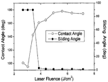
- FIG. 13 is a graph showing changes in contact angle and sliding angle of a modified surface by controlling the fluence of an ultrafast laser
- FIG. 14 is a view showing the moving picture screen for observing the flow of the water droplets in the open fluid transfer device manufactured according to the present invention for each time zone.
- the fluid transfer device is an open type or a closed type fluid transfer device in which at least two ends and at least one side are not closed or only two ends are open, and the open fluid transfer device is a macroscopically flat plate, a macroscopic curvature. And a plate having at least one side and an open polygonal, oval, and circular tube, wherein only two ends are open.
- the closed fluid transfer device includes a polygonal tube and an elliptical, circular tube. At this time, the hermetic fluid transfer device is characterized in that the microfluidic pipe.
- the fluid conveying apparatus is a hermetic or open fluid conveying apparatus as described above, which specifies a surface in contact with the fluid and delivers the fluid with minimum energy.
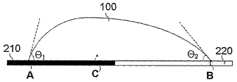
- FIG. 1 illustrates an example of a surface (only) contacting a fluid, which is a liquid to be transferred, in an open or closed fluid transfer device according to the present invention, the surface having surfaces 210 and 220 having different contact angles from the fluid. ) Is alternately formed in the conveying direction of the fluid (flow path which is an artificial fluid flow direction), and is repeatedly formed, and the fluid is conveyed by the force generated by the difference in the contact angle (hydrodynamic force). .
- the liquid to be conveyed in particular, the liquid to be conveyed discontinuously in the form of a plurality of droplets, has a solid-liquid interface / solid-gas interface / liquid-gas interface at three-phase contact points (A and B).
- the interfacial tension equilibrium is achieved by the three interfacial energies of, and at the surface 210 where the solid-liquid interfacial energy is similar to the solid-gas interface energy, it has a high contact angle ( ⁇ 1), and the solid-liquid interfacial energy is higher than the solid-gas interface energy.
- the low surface 220 has a relatively low contact angle ⁇ 2.
- the fluid transfer according to the present invention described above is based on a novel water transfer mechanism found by closely observing and analyzing water pipes of plants.
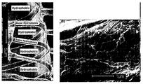
- FIG. 3 is a photograph of the lily tube's water tube structure in detail
- FIG. 3 (a) is a scanning electron micrograph observed by cutting parallel to the direction of the tube of water.
- a helical microstructure having a diameter of several micrometers exists inside the water pipe in a helical or double helical form, and its surface is coated with lignin.
- micro-rings were observed on the inner wall of the water pipe in an inclined oblique direction with an angle of about 60 ° with respect to the water pipe running direction.
- Figure 3 (b) is a scanning electron micrograph of the surface of the microstructure of the water tube at a higher magnification, it can be seen that the lignin is applied to the surface of the microstructure in a disordered form in the size of tens to hundreds of nanometers.
- the effect of these micro-nano hybrid structures on rheological properties is known as the Lotus-effect, and the surface is superhydrophobic (or superhydrophobicity).
- the Applicant believes that the rheological state of the surface of the water pipe is a variation of the regular and repetitive rheology of the microstructure having the superhydrophobicity in the region with the fine helix and the water repellency of the surface between the gaps. It has been found that water is transported from the water ducts of plants by the hydrodynamics forces caused by it.
- the present invention is directed to a surface having a contact angle different from that of a fluid on the surface of a device that is in contact with the fluid to provide a fluid flow path in the direction of transport of the fluid (the flow path of the artificial fluid).
- a device that consumes a minimum of external energy to enable fluid transfer vertically and horizontally.
- the difference in the contact angle, the length of the surface having one contact angle in the direction of fluid movement, and the surfaces having different contact angles are basically different according to the size of the droplet. Spacing, etc. based on the direction of fluid movement should be determined.
- the droplets should have a volume transportable in the horizontal to vertical direction by the force caused by the difference in contact angle, ignoring gravity, with the density of the droplets also being taken into account.
- the droplets are generally about 3-4 ul or less by volume due to buoyancy pressure in the air and adhesion force of the material, and the diameter of the tubular conveying device, which is an embodiment of the present invention, is large. Since the effect of the gradient force of the wall surface can be canceled by gravity when there is a gravity effect of its own, the volume of the droplet is preferably a droplet having a volume of 0.004 ⁇ m 3 or less, and substantially 1 nm 3 to 0.004 ⁇ m 3 Droplets having a volume are preferred.
- the fluid sliding angle is preferably 0 ° to 5 ° on all surfaces in contact with the fluid to be moved.
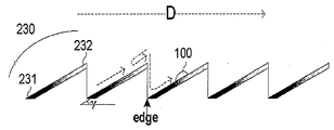
- Figure 4 is a cross-sectional view of an open fluid transfer device according to the present invention, a cross-sectional view of the plate is formed in the sawtooth irregularities.
- the tooth surface 230 (mount surface forming the acid) of the plate is characterized in that it has a surface which continuously decreases the contact angle from one surface 231 having a relatively high contact angle to one surface 232 having a relatively low contact angle. have.
- the above-described movement of the droplet 100 may be more continuously performed by continuously decreasing the contact angle at the tooth surface 230.
- the droplet 100 is transferred from one surface 231 of the high contact angle of the tooth surface to the end of the one surface 232 of the low contact angle, the droplet is transferred to the physical vibration, static electricity or electric field caused by inertia, external device, wind power, etc. It is transferred to the edges by vibrations caused by force, physical force and thermal energy generated by electromagnetic fields.
- the droplets transferred to the end of the one surface 232 of the low contact angle may be moved back toward the one surface 231 or the valley of the high contact angle, but the droplets moved toward the one surface 231 of the high contact angle may be moved.
- the force of the contact angle difference described above is transferred back to the end of one surface 232 of the low contact angle, as a result, all of the droplets 100 are transferred in a single direction (D).
- Figure 5 is a perspective view of the open fluid transfer device according to the present invention, in the region 200 and the direction to transfer the fluid in the tooth surface of the plate 200, not the entire area of the surface of the surface of the serrated irregularities formed plate 200
- a specific flow path may be formed on the surface of the plate by forming a surface 230 in which the contact angle decreases continuously from one surface 231 having a high contact angle in a predetermined region to one surface 232 having a relatively low contact angle.
- the maximum difference of the continuously varying contact angles is 3 ° to 180 °
- the length L of the tooth surface 230 is 100 to 5000 ⁇ m
- the angle ( ⁇ ) is preferably 7 ° to 90 °.
- FIG. 6 to 10 is an example of the hermetic fluid transfer device according to the present invention, in detail a cylindrical microtube
- Figure 9 is the case where the irregularities are not formed in the inner surface of the tube
- Figures 6, 8 to 10 is the inner surface of the tube
- FIGS. 8 to 10 In the case where the irregularities are formed in the surface having a high contact angle with the fluid, which is the liquid to be transferred, has a curvature and protrudes (FIGS. 8 to 10) and an example in which a tooth-shaped uneven surface 230 similar to FIG. 4 is formed ( Figure 6) is shown, and all have the direction of fluid transfer from the lower part of the tube to the upper part of the tube.
- the material of the pipe 200 may be a metal, ceramic, polymer or glass without considering the contact angle with the fluid, if there is irregularities, the irregularities formed on the inner surface of the tube is also made of the same material as the material of the tube , A surface 230 having a continuous contact angle decreasing at one surface 231 of high contact angle or one surface 210 having high contact angle and a low contact angle using only coating, deposition, surface modification, etc. on the inner surface of the tube.
- Surface 220 may be provided.
- the material of the pipe 200 may be a metal, a ceramic, a polymer or a glass material having a low contact angle with the fluid to be transferred. If the unevenness is present, the unevenness formed on the inner surface of the pipe may be made of the same material as the material of the pipe. Using surface modification, a surface 230 having a continuously increasing contact angle or a surface 210 having a high contact angle may be provided.
- the material of the pipe 200 may be a metal, ceramic, polymer, or glass having a high contact angle with the fluid to be transferred. If the unevenness is present, the unevenness formed on the inner surface of the pipe may be made of the same material as that of the pipe.
- a surface 230 having a continuously decreasing contact angle using surface modification or one surface 220 having a low contact angle may be provided.
- the inner diameter (d) of the tube is preferably 100 ⁇ m to 2000 ⁇ m.
- a single tooth surface in the toothed surface irregularities has a low contact angle at one surface (lower position) of a high contact angle similar to that described above with reference to FIG. 4. It consists of one surface (upper position) of, the maximum difference of the continuously changing contact angle in the single tooth surface is 3 ° to 180 °, the length of the tooth surface 230 is 100 to 5000 ⁇ m, the tooth surface fluid transfer
- the angle ⁇ formed in the direction (long axis direction of the tube) is preferably 7 ° to 90 °.
- FIG. 7 illustrates a case where surface irregularities are not formed, and each of the surfaces 210 having a high contact angle with a droplet and a surface 220 having a low contact angle are closed bands 210 and 230 having both ends connected to each other. This is a case where the surface is formed, and the center line in the width direction of the closed strips 210 and 230 and the fluid conveying direction (the longitudinal direction of the tube) are 90 degrees.
- FIG. 7 is only one example of an alternately repeated inner tube surface of a surface having a high contact angle and a surface having a low contact angle with respect to a direction in which the fluid is conveyed, and the widthwise direction of the closed strips 210 and 230. It goes without saying that the centerline and the fluid transfer direction (the longitudinal direction of the tube) may have an angle of 90 degrees or less.
- the inner surface of the tube may be alternately formed by alternately forming a band of spirals having different contact angles instead of the closed band shown in FIG. 7.
- the hermetic fluid transfer device in which the unevenness is formed, which is an example in which the curved curved portion has a surface having a high contact angle with the fluid to be transferred.
- the inner surface of the tube is alternated between the surface 210 having a high contact angle and the surface 220 having a low contact angle, and the surfaces having different contact angles have opposite ends. It has a connected band shape (including a constant area curvature band shape by the protruding portion), and the conveying direction of the fluid (the longitudinal direction of the tube) and the width center line of the band have a relationship of 90 degrees.
- FIG. 8 (b) is a perspective view showing only the inner surface of the tube having the cross section of FIG. 8 (a), wherein the widths t1 and t2 of the surface 210 having a high contact angle and the surface 220 having a low contact angle are respectively Independently of each other, it is preferably 0.0001 to 5 times based on the diameter (d) of the tube.
- the width t2 of the surface 210 having the larger contact angle is narrower among the surfaces having different contact angles, and the same contact angle as the surfaces 210 and 220 having different contact angles are alternated.
- the surface having a different width can be of course.
- the protrusion on which the surface 210 having the high contact angle is formed is a protrusion having a smooth shape in which the change in curvature is continuous, and the protrusion has both negative curvature and positive curvature based on the central axis of the tube.
- the height h of the protrusion protrudes is preferably 0.0001 times to 0.01 times the diameter d of the tube.
- FIG. 9 illustrates an example in which the conveying direction of the fluid (the longitudinal direction of the tube) and the width center line of the band have a predetermined angle, wherein the widths of each of the high contact angle surface 210 and the low contact angle surface 220 are different from each other.
- t1, t2) means the shortest width and shows the case where a tubular material consists of a material with a low contact angle, and has a high contact angle surface by surface modification of a tubular material.
- belt make is 20 degrees-70 degrees.
- FIG. 10 illustrates a case in which the inner surface of the tube is formed by the repetition of a spiral band instead of a closed band, and the inner surface of the tube is divided into two spirals of the surface 210 having a high contact angle and a spiral of the surface 210 having a high contact angle. If configured.
- the surface 210 having a high contact angle is shown as having a single spiral structure, the surface 210 having a high contact angle may have a double or more spiral structure having the same width or different widths. Of course.
- the tangent at the width center line of the spiral band preferably has an angle of 20 ° to 70 ° with respect to the fluid conveying direction (the longitudinal direction of the tube).
- the hermetic fluid transfer device of the present invention has the spiral structure of FIG. 10 in view of further lowering of contact resistance according to the micro-nano structure (surface irregularities) and providing continuous force in transporting droplets. It is desirable to have a similar structure.
- FIG. 11 illustrates an application of the fluid transfer device of the present invention and illustrates a transfer unit configured to transfer fluid in a vertical direction by being composed of a plurality of hermetic fluid transfer devices of FIG. 10.
- the fluid to be transferred in the fluid transfer device according to the present invention described above is characterized in that the water.
- the surfaces 210 and 220 having different contact angles from the fluid are characterized as being hydrophobicity surfaces and superhydrophobicity surfaces.
- the contact angle (contact angle with the water droplets) of the super water-repellent surface is greater than the contact angle (contact angle with the water droplets) of the water-repellent surface, and the contact angle with the fluid of the water-repellent surface is 80 ° to 120 °, It is preferable that the water contact angle is 90 degrees to 180 degrees.
- the water repellent surface and the super water repellent surface are each characterized by a polymer surface, and the super water repellent surface is characterized by being formed by ultrafast laser beam irradiation treatment on the water repellent surface.
- the water-repellent surface is characterized in that the surface of polydimethylsiloxane (poly (dimethylsiloxane), hereinafter PDMS).
- the ultra-fast laser has a femtosecond pulse
- the wavelength of the ultra-fast laser beam is 700 ⁇ 1000 nm
- the pulse width is 100 ⁇ 200 fs
- the substrate transfer speed is 3 ⁇ 5 mm / sec
- between the laser beam spot The spacing is 3 to 5 mu m
- the chromatic aberration NA of the objective lens for adjusting the focus of the femtosecond laser beam is 0.1 to 0.2
- the size of the laser beam spot on the substrate surface is 6 to 9 mu m.
- the fluence of the ultra-fast laser is 2 ⁇ 8 J / cm 2
- the number of average laser pulses irradiated to the substrate surface is preferably 1.5 to 2.5.
- the fluence of the ultra-fast laser for reforming to have a contact angle of 90 ° to 180 ° with the contacted fluid is characterized in that 2 to 8 J / cm 2
- the ultra-high speed for reforming to have a flow angle of 5 ° or less The fluence of the laser is characterized by 4 to 8 J / cm 2 .
- an open fluid transfer device having a structure similar to that of FIG. 3 was prepared using surface modification by polydimethylsiloxane and laser beam.
- a stainless metal plate surface was manufactured to have a cross section similar to that of FIG. 3.
- the prepolymer and initiator of PDMS were agitated at 10: 1, applied onto a stainless mold, and then polymerized to form a PDMS material as shown in FIG. 12 (b).
- the substrate of the fluid transfer apparatus was manufactured.
- substrate was 5.0 mm, and the inclination angle (gamma) of the tooth surface was 12 degrees.
- the surface of the fabricated PDMS substrate was partially irradiated with ultrafast laser to modify the surface rheological properties.
- the PDMS plate was mounted on an orthogonal XY-stage and the substrate was moved at a speed of 4 mm / sec in the x-axis direction. The distance between each laser spot is 4 um considering the moving speed and the repetition speed of the laser. .
- the average number of laser pulses irradiated on the PDMS surface of each part is limited to about 1.9 times to minimize the accumulated thermal effect that may be caused by repeated irradiation of ultrafast lasers irradiated at 1 ms time (1 kHz) intervals. .
- the contact angle is about 165 ° and the slip angle is 3 ° or less, so it belongs to the Cassie-Boxter (C-B) model.
- the superhydrophobic PDMS surface could be prepared by irradiation of the surface under ultra-fast laser fluence of moderate strength.
- the surface microstructure of the surface-treated PDMS is micro-sized with micro-sized structure. Properly placed on the structure, a very rough surface state is realized, which is equivalent to the microstructure of the superhydrophobic surface found in nature.
- FIG. 13 is a graph showing changes in contact angle and sliding angle by controlling the fluence of an ultrafast laser.
- the fluence of the ultrafast lasers having a contact angle of 90 ° to 170 ° is 2 to 8 J / cm 2
- the fluence of the ultrafast lasers having a sliding angle of 3 ° or less is 4 to 8 J / cm 2 . have.
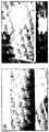
- FIG. 14 shows a video screen for observing the flow of water droplets observed using an open fluid flow device similar to FIG. 3 manufactured by PDMS and ultrafast femtosecond laser irradiation.
- the water droplets roll from the marked (a) point (super water-repellent area) very quickly to reach the last point (near the edge) to the point (b) (water-repellent area of PDMA itself). Able to know.
- the hermetic fluid transfer device can be microfluidized in the following way.
- substrate is made thin enough, and the surface is produced so that a micro structure (projection part) may become a fixed angle with the diagonal line of a water flow direction.
- the angle between the microstructure and the water flow direction can be accurately predicted and designed by considering the relationship between the diameter of the microfluidic pipe and the design.
- the PDMS surface designed by the above method can change the rheological properties by the above-described laser irradiation method or other conventional methods, and then achieve this in the form of a tube to complete the hermetic microfluidic pipe designed in the present invention.
Landscapes
- Engineering & Computer Science (AREA)
- Mechanical Engineering (AREA)
- General Engineering & Computer Science (AREA)
- Physical Or Chemical Processes And Apparatus (AREA)
- Reciprocating Pumps (AREA)
- Micromachines (AREA)
Abstract
본 발명은 이송대상 액인 유체를 수직 내지 수평으로 이송하는 장치에 관한 것으로, 상세하게는 상기 유체와 서로 다른 접촉각(contact angle)을 갖도록 상기 유체의 이송방향으로 교번되어 반복적으로 표면이 형성되고, 상기 접촉각의 차이로 발생하는 힘(hydrodynamic force)에 의해 상기 유체가 이송되는 특징이 있다. 본 발명에 따른 유체 이송 장치, 상세하게는 유체 이송을 위한 미세 유체 관은 외부장치, 풍력 등에 의한 물리적 진동, 정전기 혹은 전기장에 의하여 발생하는 전자기장에 의한 힘, 물리적 힘, 열 에너지에 의한 진동 등을 포함하는 외부 에너지 소비를 최소로 소요하며 펌프를 이용하지 않고 유체를 수직 내지 수평 방향으로 이송시키는 장점이 있다.
Description
본 발명은 이송대상 액인 유체를 수직 내지 수평으로 이송하는 장치에 관한 것으로, 에너지 소비를 최소화하며 그 이송 방향을 제어할 수 있는 새로운 구조의 유체 이송장치를 제공하는 것이다.
물 및 다양한 액체를 이송하고 이를 제어할 수 있는 기술 및 장치에 대한 요구는 매우 다양한 형태로 제기된다. 특히 현재와 같은 고유가 및 환경문제에 의한 에너지/환경 문제가 매우 주요한 시점에서 이러한 위기상황을 매우 슬기롭게 대처할 수 있기 위해서는 다양한 분야에서 응용 가능하며 저 에너지 소비 및 환경친화적인 액체 이송 기술 개발에 반드시 필요하다.
액체의 이송 및 수송에 관한 고체 표면개질에 관한 연구는 지난 반세기 동안 매우 활발하게 이루어지고 있다. 특히 장치의 표면에 다양한 물리 화학적인 성질을 개질함으로써 물흐름에 관여하는 물리적인 특성을 일정한 기울기를 갖도록 하는 방법이 개발되어 왔다.
일 예로, 표면 개질에 관한 기술은 주로 이제까지 잘 알려진 방법인 그래프팅-프럼 중합법(grafting-from polymerization)이나 플라즈마(plasma) 혹은 코로나 방전의 정도를 제어함으로써 표면성질을 개질하고자하는 연구개발이 시도되고 있다. 이를 위하여 다양한 버텀-업(bottom-up) 및 탑-다운(top-down)형의 리소그래픽(lithographic) 및 비리소그래픽(nonlithographic) 방법이 이미 개발되어 있으나 이는 주로 일정 거리에서만이 응용이 가능하다는 한계점에 봉착되어 있다(J. Genzer et al, "Surface-Bound Soft Matter Gradients", Langmuir, 24, 2294-2317, 2008).
상술한 바와 같은 표면개질을 통한 물흐름 제어와는 원리적으로 전혀 다르지만 2006년도 히팅 플레이트(heating plate)에서의 물방울 이동에 관한 물리적인 해석을 통한 물 이동제어에 관한 연구보고가 있었으나(H. Linke et al, "Self-Propeeled Leidenfrost Droplets", Phys. Rev. Lett., 96, 154502-1-154502-4, (2006)), 이는 에너지 소모적인 형태이다.
한편 식물체 물관부에서의 물의 수송에 관한 기존의 기술 개발은 주로 환경관련 중금속의 제거 등 응용 적인 측면에서 연구가 주로 수행되고 있다.
이러한 연구는 주로 분자생물학적인 측면에서의 식물체 형질 전환을 통하여 효율을 증대하고 효과를 최적화하는 방향으로 진행되고 있다.
물관의 물이송에 관한 개발 분야는 현재 주로 거시적인 측면에서의 뿌리 주위에 있는 토양 및 수분의 이온의 종류 및 이온의 농도 등을 포함하는 성분주위환경 변화에 따른 물 수송 속도론적인 측면에서의 연구가 주로 이루어지고 있다. 물관부 성분인 셀룰로스, 헤미셀룰로스, 리그닌 등의 생합성에 관련하는 유전자의 발굴과 돌연변이에 의한 구조적 변화에 대한 기능유전체학적 연구가 모델식물인 1년생 잡초인 애기장대를 대상으로 활발하게 진행되고 있으나 물의 수송에 어떠한 영향을 미치는지에 대한 연구와 단자엽 식물이나 목본식물에 대한 연구는 거의 진행된 바 없다.
본 발명의 목적은 이송대상 액인 유체를 수직 내지 수평으로 이송하는 장치를 제공하는 것이다.
상세하게는 최소의 에너지를 소비하며 유체를 이송할 수 있는 친환경적인 유체 이송 장치를 제공하는 것이며, 외부와 열 교환을 매우 효율적으로 수행할 수 있으며, 외부의 물리적인 충격이나 휨작용과 같은 기계적인 영향으로부터 유체의 이송 능력 및 장치의 손상을 최소화 할 수 유체 이송 장치를 제공하는 것이다.
본 발명에 따른 유체 이송 장치는 이송대상 액인 유체와 서로 다른 접촉각(contact angle)을 갖도록 상기 유체의 이송방향으로 교번되어 반복적으로 표면이 형성되고, 상기 접촉각의 차이로 발생하는 힘(hydrodynamic force)에 의해 상기 유체가 이송되는 특징이 있다.
상기 서로 다른 접촉각을 갖는 표면의 상기 유체 흐름각(sliding angle)은 0˚ 내지 5˚인 것이 바람직하며, 실질적으로는 0.1˚ 내지 5˚인 것이 바람직하다.
상기 서로 다른 접촉각을 갖는 표면의 접촉각 차는 3˚ 내지 180˚인 것이 바람직다.
상기 표면은 상기 유체와의 접촉각이 일 접촉각에서 타 접촉각으로 연속적으로 증가하는 표면이 톱니형으로 반복적으로 형성되어 있는 특징이 있다.
상기 표면은 관 내면이며, 서로 다른 접촉각을 갖는 양 단이 연결된 폐형 띠 표면; 또는 나선형 표면;이 교번되어 반복적으로 형성되어 있는 특징이 있다.
이때, 상기 서로 다른 접촉각을 갖는 표면간 단차가 형성된 특징이 있으며, 상기 서로 다른 접촉각을 갖는 표면 중 큰 접촉각을 갖는 표면이 곡률을 가지며 돌출되어 있는 특징이 있다.
상기 관의 지름은 100 내지 2000 ㎛인 것이 바람직하며, 상기 띠 또는 나선형 표면의 폭은 상기 관의 지름을 기준으로 0.0001배 내지 5배인 것이 바람직하다.
이때, 상기 서로 다른 접촉각을 갖는 표면 중 큰 접촉각을 갖는 표면의 폭이 더 좁은 특징이 있다.
상기 나선형 표면에서 나선 중심의 접선은 상기 관의 길이 방향에 대하여 20˚ 내지 70˚의 각도를 갖는 것이 바람직하다.
상기 단차는 상기 관의 지름을 기준으로 0.0001배 내지 0.01배인 것이 바람직하다.
본 발명에 따른 유체 이송 장치의 이송 대상 유체는 물인 특징이 있다. 이때, 상기 유체와 서로 다른 접촉각을 갖는 표면은 발수성(hydrophobicity) 표면 및 초발수성(superhydrophobicity) 표면인 특징이 있다.
상기 발수성 표면 및 초발수성 표면은 각각 고분자 표면인 특징이 있으며, 상기 초발수성 표면은 발수성 표면에 초고속 레이저 빔 조사 처리하여 형성된 특징이 있다.
이때, 상기 발수성 표면은 폴리디메틸실록산(poly(dimethylsiloxane), PDMS) 표면인 특징이 있다.
본 발명에 따른 유체 이송 장치는 자연계에 존재하는 바람이나 인위적인 진동과 같은 최소의 에너지를 이용하여 유체를 수직 내지 수평 방향으로 이송 가능하며, 유체가 이송 되는 방향의 제어가 가능한 장점이 있다.
또한 밀폐형 유체 이송 장치의 경우 매우 미세한 관의 형상을 가져 외부 장치와 열적인 에너지 교환을 매우 효율적으로 수행하며, 외부의 물리적인 충격이나 휨작용과 같은 기계적인 영향에 의한 손상을 최소화 할 수 있으며, 거의 모든 고분자 및 금속 혹은 비금속등 다양한 물질을 이용하여 제조 가능하며, 고층 건물용 유체 수송 시스템 뿐만 아니라 냉각용 모터가 필요 없는 초 절전 무소음 쿨러, 유체 펌프가 필요 없는 바이오 칩, 마이크로 플루이딕스 칩등 다양한 분야에 활용 가능한 장점이 있다.
도 1은 본 발명에 따른 개방형 또는 밀폐형 유체이송 장치에서 이송 대상 액인 유체와 맞닿는 표면(만)을 도시한 일 예이며,
도 2는 서로 다른 접촉각을 갖는 액적의 단면을 도시한 개념도이며,
도 3은 백합 줄기의 물관 구조를 정밀 관찰한 주사전자현미경 사진이며,
도 4는 본 발명에 따른 개방형 유체이송장치의 일 단면도이며,
도 5는 본 발명에 따른 개방형 유체이송장치의 일 사시도로이며,
도 6은 본 발명에 따른 밀폐형 유체이송장치의 일 예이며,
도 7은 본 발명에 따른 밀폐형 유체이송장치의 다른 예이며,
도 8은 본 발명에 따른 밀폐형 유체이송장치의 또 다른 예이며,
도 9는 본 발명에 따른 밀폐형 유체이송장치의 또 다른 예이며,
도 10은 본 발명에 따른 밀폐형 유체이송장치의 또 다른 예이며,
도 11은 본 발명의 유체 이송 장치의 일 활용예이며,
도 12는 본 발명에 따라 실 제작한 개방형 유체이송장치의 몰드 및 PDMS 기판의 광학 사진이며,
도 13은 초고속 레이저의 플루언스를 제어함으로써 개질 표면의 접촉각과 슬라이딩 각의 변화를 도시한 그래프이며,
도 14는 본 발명에 따라 실 제작한 개방형 유체이송장치에서 수 액적의 흐름을 관찰한 동영상 화면을 각각의 시간대별도 도시한 도면이다.
*도면의 주요 부분에 대한 부호의 설명*
100 : 액적 210 : 고 접촉각 표면
220 : 저 접촉각 표면 230 : 톱니면
231 : 톱니면의 고접촉각 영역 232 : 톱니면의 저접촉각 영역
233 : 고 접촉각 영역 200 : 관
이하 첨부한 도면들을 참조하여 본 발명의 유체 이송 장치를 상세히 설명한다. 다음에 소개되는 도면들은 당업자에게 본 발명의 사상이 충분히 전달될 수 있도록 하기 위해 예로서 제공되는 것이다. 따라서, 본 발명은 이하 제시되는 도면들에 한정되지 않고 다른 형태로 구체화될 수도 있다. 또한 명세서 전체에 걸쳐서 동일한 참조번호들은 동일한 구성요소들을 나타내며, 제시된 도면은 구조의 명확함을 위해 일정 부분 과장되어 도시될 수 있다.
이때, 사용되는 기술 용어 및 과학 용어에 있어서 다른 정의가 없다면, 이 발명이 속하는 기술 분야에서 통상의 지식을 가진 자가 통상적으로 이해하고 있는 의미를 가지며, 하기의 설명 및 첨부 도면에서 본 발명의 요지를 불필요하게 흐릴 수 있는 공지 기능 및 구성에 대한 설명은 생략한다.
본 발명에 따른 유체 이송 장치는 적어도 두 단부 및 적어도 일 측면이 밀폐되지 않은 개방형 또는 두 단부만이 개방된 밀폐형 유체이송 장치이며, 상기 개방형 유체 이송 장치는 거시적으로 편평한 플레이트(palte), 거시적으로 곡률을 갖는 플레이트(plate) 및 적어도 일측면이 개방된 다각형, 타원형 및 원형관을 포함하며, 두 단부만이 개방된 밀폐형 유체이송 장치는 다각형 관 및 타원형, 원형관을 포함한다. 이때, 상기 밀폐형 유체이송 장치는 미세유체관인 특징이 있다.
본 발명에 따른 유체 이송장치는 상술한 밀폐형 또는 개방형 유체이송장치로, 유체와 맞닿은 표면을 특정지어, 최소 에너지를 공급받아 유체를 이송시킨다.
도 1은 본 발명에 따른 개방형 또는 밀폐형 유체이송 장치에서 이송 대상 액인 유체와 맞닿는 표면(만)을 도시한 일 예로, 상기 표면은 상기 유체와 서로 다른 접촉각(contact angle)을 갖는 면(210 및 220)이 상기 유체의 이송방향(인위적인 유체의 흐름 방향인 유로)으로 교번되어 반복적으로 형성되어 있는 특징이 있으며, 상기 유체는 상기 접촉각의 차이로 발생하는 힘(hydrodynamic force)에 의해 이송되는 특징이 있다.
보다 상세하게, 도 2에 도시한 바와 같이 이송 대상 유체(100)와 고 접촉각을 갖는 표면(210)과 상대적으로 저 접촉각을 갖는 표면(220)이 연속적으로 교번되어 반복된 특징을 가짐에 따라, 이송 대상 유체, 상세하게는 다수개의 액적의 형태로 불연속적으로 이송되는 이송 대상 액적은 삼상(three phase)이 접하는 곳(A, B)에서 고상-액상 계면/ 고상-기상 계면/ 액상-기상 계면의 세 계면 에너지에 의한 계면 장력 평형이 이루어지며 고상-액상 계면 에너지가 고상-기상 계면 에너지와 유사한 표면(210)에서는 고 접촉각(θ1)을 가지며, 고상-액상 계면 에너지가 고상-기상 계면 에너지보다 낮은 표면(220)에서는 상대적으로 저 접촉각(θ2)을 갖게 된다.
도 2에 도시한 바와 같이 단일한 액적(100) 내에서 서로 다른 접촉각(θ1, θ2)이 형성되면, 이러한 접촉각의 차이(Δθ=θ1-θ2)로 발생하는 힘에 의해 액적(100)이 고 접촉각을 갖는 표면(210)에서 저 접촉각을 갖는 표면(220)으로 이송된다.
상술한 본 발명에 따른 유체 이송은 식물의 물관을 정밀 관찰 및 분석하여 발견한 새로운 물 이송 메커니즘에 근간한 것이다.
도 3은 백합 줄기의 물관 구조를 정밀 관찰한 사진으로, 도 3(a)는 물관의 방향에 평행하게 커팅하여 관찰한 주사 전자 현미경 사진이다. 도 3(a)에서 알 수 있듯이 수 마이크로미터의 지름을 갖는 나선형 형태의 마이크로 구조가 나선(helical) 혹은 이중 나선(double helical) 형태로 물관 내부에 존재하며, 그 표면이 리그닌으로 도포되어 있다.
또한 식물의 종류에 따라 물관의 진행 방향에 대하여 약 60ㅀ 정도의 각을 갖고 기울어진 사선 방향으로 마이크로 링(ring)이 물관 내부벽에서 관찰되기도 하였다.
도 3(b)는 이러한 물관의 마이크로 구조 표면을 좀 더 고배율로 관찰한 주사 전자 현미경 사진으로써, 리그닌이 수십에서 수백 나노미터의 크기로 무질서한 형태로 마이크로 구조물 표면에 도포되어 있음을 알 수 있다. 이러한 마이크로-나노 하이브리드 구조형태가 유변학적인 성질에 미치는 영향은 일명 로터스-효과(Lotus-effect)라 하여 잘 알려져 있으며, 이 표면은 초소수성 (혹은 초발수성, superhydrophobicity)의 성질을 띤다.
한편 이러한 마이크로 사이즈의 나선이 표면에 거치할 때 그 간격사이의 물관 표면은 마이크로 구조는 없으나 리그닌이 상당 부분 도포되어 있음을 알 수 있다. 따라서 이 부분은 소수성 성질의 리그닌에 의하여 상당 수준의 발수성의 표면 성질 띤다.
이를 통해 본 출원인은 물관 표면의 유변학적인 상태는 미세 나선이 있는 부분에서의 초발수성과 그 간격 사이의 표면의 발수성을 갖는 미세 구조의 규칙적이고 반복적인 유변성질의 변이가 존재하며, 이러한 발수성 차이에 의해 야기되는 유변학적 힘(hydrodynamics force)에 의해 식물체의 물관에서 물이 이송됨을 발견하였다.
본 발명은 이러한 발견을 기반으로 유체와 접촉하여 유체 이동 통로를 제공하는 장치의 표면에 유체와 서로 다른 접촉각(contact angle)을 갖는 면이 상기 유체의 이송방향(인위적인 유체의 흐름 방향인 유로)으로 교번되어 반복적으로 형성됨에 따라, 최소의 외부 에너지를 소모하여 수직 내지 수평으로 유체 이송을 가능하게 하는 장치를 제공하는 것이다.
상술한 접촉각의 차에 의해 야기된 힘에 의한 액적(100)의 이동시 기본적으로 액적의 크기에 따라 상기 접촉각의 차, 일 접촉각을 갖는 표면의 유체 이동방향으로의 길이, 서로 다른 접촉각을 갖는 표면 간의 유체 이동방향을 기준으로 한 간격등이 결정되어야 한다.
바람직하게, 상기 액적은 중력을 무시하고 상기 접촉각의 차에 의해 야기된 힘에 의해 수평 내지 수직의 방향으로 이송 가능한 부피를 가져야 하며, 이때, 액적의 밀도 또한 고려되어야 한다.
액적이 일반적으로 공기중 buoyancy pressure 및 물자체의 adhesion force에 의하여 중력의 영행을 무시할 만큼 작은 경우가 부피로 약 3-4 ul 이하인 것으로 알려져 있으며, 본 발명의 일 실시예인 관형 이송장치의 지름이 커서 그 자체의 중력 효과가 있는 경우 벽면의 gradient force의 영향이 중력과 상쇄될 수 있으므로, 상기 액적의 부피는 0.004 ㎛3이하의 부피를 갖는 액적이 바람직하며, 실질적으로는 1nm3 내지 0.004 ㎛3의 부피를 갖는 액적이 바람직하다.
바람직하게, 액적의 효과적인 이송을 위해, 상기 서로 다른 접촉각을 갖는 표면의 접촉각 차(Δθ=θ1-θ2)는 3˚ 내지 180˚이며, 표면과 유체의 접촉시 저항(drag force)에 의한 이송 효율 저하를 방지하기 위해, 이동 대상 유체와 접하는 모든 표면에서 상기 유체 흐름각(sliding angle)은 0˚ 내지 5˚인 것이 바람직하다.
도 4는 본 발명에 따른 개방형 유체이송장치의 일 단면도로, 톱니형으로 요철이 형성된 플레이트의 일 단면도이다.
상기 플레이트의 톱니면(230, 산을 형성하는 면)은 상대적으로 고 접촉각을 갖는 일 표면(231)에서 상대적으로 저 접촉각을 갖는 일 표면(232)로 연속적으로 접촉각이 감소하는 표면을 갖는 특징이 있다.
도 4와 같이 톱니면(230)에서의 접촉각이 연속적으로 감소하게 함으로써 상술한 액적(100)의 이동이 보다 연속적으로 수행될 수 있다. 액적(100)이 톱니면의 고 접촉각의 일 표면(231)에서 저 접촉각의 일 표면(232)의 끝까지 이송 된 후, 상기 액적은 이송되던 관성, 외부장치, 풍력 등에 의한 물리적 진동, 정전기 혹은 전기장에 의하여 발생하는 전자기장에 의한 힘, 물리적 힘 및 열 에너지에 의한 진동에 의해 골(edge)로 이송된다.
이때, 상기 저 접촉각의 일 표면(232)의 끝까지 이송된 액적은 확률적으로 다시 고 접촉각의 일 표면(231)쪽 또는 골쪽으로 움직일 수 있으나, 고 접촉각의 일 표면(231) 쪽으로 움직인 액적은 상술한 접촉각 차에 의한 힘에 의해 다시 저 접촉각의 일 표면(232)의 끝까지 이송됨에 따라, 결과적으로 모든 액적(100)은 단일한 방향(D)로 이송된다.
도 5는 본 발명에 따른 개방형 유체이송장치의 사시도로, 톱니형 요철이 형성된 플레이트(200)에서 요철 표면의 전 영역이 아닌 플레이트(200)의 톱니면 중 유체를 이송시키고자 하는 영역 및 방향으로 일정 영역에 고 접촉각을 갖는 일 표면(231)에서 상대적으로 저 접촉각을 갖는 일 표면(232)로 연속적으로 접촉각이 감소하는 표면(230)을 형성하여 플레이트 표면에 특정 유로를 형성할 수 있다. 이때, 도 5에 도시한 바와 같이 액적의 계획된 이송 방향이 아닌 유로 측면에는 가장 큰 접촉각을 갖는 표면(233)을 형성하여 액적의 유로 이탈을 미연에 방지하는 것이 바람직하다.
도 4 내지 도 5와 같은 개방형 유체 이송 장치는 이송 대상인 액적의 크기에 따라 상기 한 톱니면(230)에서 연속적으로 변하는 접촉각의 최대차, 톱니면(230)의 길이(L) 및 톱니면(230)의 기울어진 각도(γ)등이 결정되어야 한다.
상세하게, 상기 연속적으로 변하는 접촉각의 최대차(231에서의 접촉각-232에서의 접촉각)는 3˚ 내지 180˚이며, 상기 톱니면(230)의 길이(L)는 100 내지 5000 ㎛, 상기 각도(γ)는 7˚ 내지 90˚이 바람직하다.
도 6 내지 도 10은 본 발명에 따른 밀폐형 유체이송장치의 일 예로, 상세하게 원통형 미세관이며, 도 9는 관 내면에 요철이 형성되지 않은 경우이며, 도 6, 도 8 내지 도 10은 관 내면에 요철이 형성된 경우이며, 이송대상 액인 유체와 고 접촉각을 갖는 표면이 곡률을 가지며 돌출되어 있는 예(도 8 내지 도 10)와 도 4와 유사한 톱니형 요철면(230)이 형성되어 있는 예(도 6)를 도시한 것이며, 모두 관 하부에서 관 상부쪽으로 유체 이송 방향을 갖는 경우이다.
이때, 관(200)의 재질은 유체와의 접촉각을 고려하지 않은 금속, 세라믹, 고분자 또는 유리질일 수 있으며, 요철이 존재하는 경우, 상기 관 내면에 형성된 요철 또한 관의 재질과 동일한 재질로 구성되어, 관 내측의 표면에만 코팅, 증착, 표면 개질 등을 이용하여 고 접촉각의 일 표면(231)에서 연속적으로 접촉각이 감소하는 표면(230) 또는 고 접촉각의 일 표면(210) 및 저 접촉각을 갖는 일 표면(220)이 구비될 수 있다.
이때, 관(200) 재질은 이송 대상 유체와 저 접촉각을 갖는 금속, 세라믹, 고분자 또는 유리질일 수 있으며, 요철이 존재하는 경우, 상기 관 내면에 형성된 요철 또한 관의 재질과 동일한 재질로 구성되어, 표면 개질을 이용하여 연속적으로 접촉각이 증가하는 표면(230) 또는 고 접촉각의 일 표면(210)이 구비될 수 있다.
이때, 관(200) 재질은 이송 대상 유체와 고 접촉각을 갖는 금속, 세라믹, 고분자 또는 유리질일 수 있으며, 요철이 존재하는 경우, 상기 관 내면에 형성된 요철 또한 관의 재질과 동일한 재질로 구성되어, 표면 개질을 이용하여 연속적으로 접촉각이 감소하는 표면(230) 또는 저 접촉각의 일 표면(220)이 구비될 수 있다.
도 6 내지 도 10에 도시된 관의 지름, 상세하게는 관의 내부지름(d)은 이송대상 액적의 크기를 결정하며, 0 내지 0.004 ㎛3의 부피를 갖는 다수개의 액적이 불연속적으로 이송되기 위해, 상기 관의 내부지름(d)은 100 ㎛ 내지 2000 ㎛인 것이 바람직하다.
상기 도 6과 같이 톱니형 표면 요철이 형성된 관 내면을 갖는 경우, 상기 톱니형 표면 요철에서 단일한 톱니면은 도 4를 기반으로 상술한 바와 유사하게 고 접촉각의 일 표면(하부위치)에서 저 접촉각의 일 표면(상부위치)으로 이루어지며, 상기 단일한 톱니면에서 연속적으로 변하는 접촉각의 최대차는 3˚ 내지 180˚이며, 상기 톱니면(230)의 길이는 100 내지 5000 ㎛, 톱니면이 유체 이송 방향(관의 장축 방향)과 이루는 각도(γ)는 7˚ 내지 90˚이 바람직하다.
도 7은 표면 요철이 형성되지 않은 경우를 도시한 것이며, 액적과 고 접촉각을 갖는 표면(210)과 저 접촉각을 갖는 표면(220) 각각이 양 단이 연결된 폐형 띠(210, 230)로 관 내부 표면을 형성하는 경우이며, 상기 폐형 띠(210, 230)의 폭 방향의 중심선과 유체 이송방향(관의 길이방향)이 90도 인 경우를 도시한 것이다.
그러나, 도 7은 유체의 이송방향을 기준으로 고 접촉각을 갖는 표면과 저 접촉각을 갖는 표면의 교번되어 반복 형성된 관 내면을 도시한 일 예일 뿐이며, 상기 상기 폐형 띠(210, 230)의 폭 방향의 중심선과 유체 이송방향(관의 길이방향)이 90도 이하의 각도를 가질 수 있음은 물론이다.
또한, 도 7에 도시한 폐형 띠가 아닌 서로 다른 접촉각을 갖는 나선을 이루는 띠 표면이 교번되어 반복 형성된 관 내면일 수 있다.
이하, 본 발명에 따른 밀폐형 유체 이송 장치를 표면 요철이 존재하는 경우인 도 8 내지 10을 기반으로 보다 상세히 상술하나, 요철이 형성되지 않은 경우에도 유사한 특징을 가짐은 물론이다.
도 8 내지 도 10은 요철이 형성된 밀폐형 유체이송장치의 일 예로, 곡률 진 돌출부가 이송 대상 유체와 고 접촉각을 갖는 표면을 갖는 일 예이다.
도 8(a)에 도시한 바와 같이, 관 내면은 이송대상 유체와 고 접촉각을 갖는 표면(210)과 저 접촉각을 갖는 표면(220)이 교번되어 있으며, 서로 다른 접촉각을 갖는 표면은 양 단이 연결된 띠형상(돌출부에 의해 일정영역 곡률진 띠형을 포함함)을 가지며, 유체의 이송방향(관의 길이 방향)과 띠의 폭 방향 중심선이 90도의 관계를 갖는다.
도 8(b)는 도 8(a)의 단면도를 갖는 관의 내면만을 도시한 사시도로, 고 접촉각을 갖는 표면(210) 및 저 접촉각을 갖는 표면(220)의 폭(t1, t2) 각각은 서로 독립적으로, 관의 지름(d)을 기준으로 0.0001배 내지 5배인 것이 바람직하다.
보다 바람직하게, 상기 서로 다른 접촉각을 갖는 표면 중 큰 접촉각을 갖는 표면(210)의 폭(t2)이 더 좁은 것이 바람직하며, 상기 서로 다른 접촉각을 갖는 표면(210, 220)이 교번됨에 따라 동일한 접촉각을 갖는 표면일지라도 서로 다른 폭을 가질 수 있음은 물론이다.
상기 고 접촉각을 갖는 표면(210)이 형성되는 돌출부는 곡률의 변화가 연속적인 매끄러운 형상의 돌출부인 것이 바람직하며, 상기 돌출부는 관의 중심축을 기준으로 음의 곡률 및 양의 곡률을 모두 갖는 것이 바람직하다.
상기 돌출부가 돌출된 높이(h)는 관의 지름(d)을 기준으로 0.0001배 내지 0.01배인 것이 바람직하다.
도 9는 유체의 이송방향(관의 길이 방향)과 띠의 폭 방향 중심선이 일정한 각도를 갖는 경우를 도시한 예이며, 이때, 고 접촉각 표면(210) 및 저 접촉각 표면(220) 각각의 폭(t1, t2)은 최단 폭을 의미하며, 관 재질이 저 접촉각을 갖는 물질로 구성되고, 관 물질의 표면 개질에 의해 고 접촉각 표면을 갖는 경우를 도시한 것이다.
유체의 이송방향(관의 길이 방향)과 띠의 폭 방향 중심선이 이루는 각도(α)는 20˚ 내지 70˚인 것이 바람직하다.
도 10은 폐형 띠가 아닌 나선형 띠의 반복에 의해 관 내면이 구성되는 경우를 도시한 것으로, 고 접촉각을 갖는 표면(210)의 나선과 저 접촉각을 갖는 표면(220)의 두 나선으로 관 내면이 구성되는 경우이다.
도 10의 일 예에서, 비록 고 접촉각을 갖는 표면(210)이 단일 나선 구조를 가지는 것으로 도시하였으나, 고 접촉각을 갖는 표면(210)이 그 폭이 같거나 다른 2중 이상의 나선 구조를 가질 수 있음은 물론이다.
상기 나선형 띠의 폭 중심선에서의 접선은 상기 유체 이송방향(관의 길이 방향)에 대하여 20˚ 내지 70˚의 각도를 갖는 것이 바람직하다.
도 7 내지 도 10의 일 예 중, 본 발명의 밀폐형 유체이송 장치는 미세 나노 구조(표면 요철)에 따른 접촉 저항의 추가적 저하 및 액적의 이송시 연속적인 힘의 제공 관점에서 도 10의 나선 구조와 유사한 구조를 갖는 것이 바람직하다.
도 11은 본 발명의 유체 이송 장치의 활용예를 도시한 것으로 다수개의 도 10의 밀폐형 유체이송 장치로 구성되어 수직 방향으로 유체를 이송하는 이송 유닛(unit)을 도시한 것이다.
상술한 본 발명에 따른 유체 이송 장치의 이송 대상 유체는 물인 특징이 있다. 이때, 상기 유체와 서로 다른 접촉각을 갖는 표면(210, 220)은 발수성(hydrophobicity) 표면 및 초발수성(superhydrophobicity) 표면인 특징이 있다.
상기 초발수성 표면의 접촉각(수 액적과의 접촉각)은 상기 발수성 표면의 접촉각(수 액적과의 접촉각)보다 크며, 상기 발수성 표면의 유체와의 접촉각은 80˚ 내지 120˚이며, 상기 초발수성 표면의 물 접촉각은 90˚ 내지 180˚인 것이 바람직하다.
상기 발수성 표면 및 초발수성 표면은 각각 고분자 표면인 특징이 있으며, 상기 초발수성 표면은 발수성 표면에 초고속 레이저 빔 조사 처리하여 형성된 특징이 있다. 이때, 상기 발수성 표면은 폴리디메틸실록산(poly(dimethylsiloxane), 이하 PDMS) 표면인 특징이 있다.
본 발명의 초고속 레이저를 이용한 표면 개질은 PDMS를 포함하는 고분자 기판 또는 고분자 관의 내부에 형성된 표면에 수~수백 나노미터 이하의 나노 사이즈 미세구조를 갖도록 초고속 레이저의 빔을 조사하여 초발수성 표면을 제조하는 특징이 있다.
이때, 초고속 레이저는 펨토초 펄스를 갖으며, 초고속 레이저빔의 파장은 700~1000 nm이고, 펄스폭은 100~200 fs 이며, 기판의 이송속도는 3~5 mm/sec이고, 레이저빔 spot 사이의 간격은 3~5 ㎛이며, 펨토초 레이저 빔의 초점을 조정하기 위한 대물렌즈의 색수차(N.A.)는 0.1~0.2이고, 기판 표면의 레이저빔 spot 크기는 6~9 ㎛인 것이 바람직하다. 또한, 상기 초고속 레이저의 플루언스는 2~8 J/cm2 이며, 기판 표면에 조사되는 평균 레이저 펄스의 수는 1.5~2.5 인 것이 바람직하다. 이때, 접촉되는 유체와 90˚ 내지 180˚의 접촉각을 갖도록 개질하기 위한 상기 초고속 레이저의 플루언스는 2 내지 8 J/cm2인 특징이 있으며, 5˚ 이하의 흐름각을 갖도록 개질하기 위한 상기 초고속 레이저의 플루언스는 4 내지 8 J/cm2인 특징이 있다.
본 발명의 우수함을 실험적으로 입증하기 위해, 폴리디메틸실록산 및 레이저 빔에 의한 표면개질을 이용하여 도 3과 유사한 구조를 갖는 개방형 유체 이송 장치를 제조하였다.
도 12(a)에 도시한 바와 같이 먼저 스테인레스 금속판 표면을 도 3과 유사한 단면을 갖도록 제작하였다. 이 표면을 세척한 후 PDMS의 프리폴리머(prepolymer) 및 개시제(initiator)를 10:1로 교반한 후 스테인레스 몰드(mold) 위에 도포하고 중합(polymerization) 반응을 함으로써 도12(b)와 같은 PDMS 재질의 유체 이송 장치의 기판을 제조하였다. 이때, 제작된 PDMS 기판의 단일 톱니면의 길이(L)는 5.0 mm, 톱니면이 기울어진 각도(γ)는 12˚이었다.
이후, 제작된 PDMS 기판의 톱니면에 초고속 레이저를 부분적으로 조사하여 미세공정함으로써 표면의 유변학적인 특성을 개질하였다.
파장이 810 nm 펄스폭이 150 fs (Quantronix, USA)인 레이저를 PDMS 기판 표면에 조사하였다. PDMS 판은 직교하는 XY-stage위에 거치하고 기판을 x축 방향으로 4 mm/sec의 속도로 이동시켰으며, 이때 이동속도 및 레이저의 반복속도를 고려하면 각각의 레이저 spot 사이의 간격은 4 um이다. 펨토초 레이저 빔을 Z-축으로 선형이동이 가능한 또 다른 stage위에 거치된 대물렌즈를(N.A=0.14) 통하여 PDMS 표면에 초점을 고정하여 조사하였다. 이때, 대물랜즈의 광학적인 고려를 하면 PDMS 표면의 레이저 spot 크기는 7.7 um이다. 따라서 각 부분의 PDMS 표면에 조사되는 평균 레이저 펄스의 수는 약 1.9번 정도로 제한함으로써 1 ms시간 (1 kHz) 간격으로 조사되는 초고속레이저의 반복적인 조사에 의하여 발생할 수도 있는 누적된 열 효과를 최소화하였다.
상술한 펨토초 레이저로 직접 표면개질한 PDMS 기판의 경우 접촉각은 약 165˚이며 또한 미끄러짐 각은 3˚ 이하로 Cassie-Boxter (C-B) 모델에 속함을 알 수 있다.
보다 상세하게 적당한 강도의 초고속레이저 플루언스(fluence)하에서 표면의 조사로 초발수성의 PDMS 표면을 제조 할 수 있었으며, 특히 표면 처리된 PDMS의 표면 미세구조는 나노 사이즈의 초미세구조가 마이크로 사이즈의 미세구조위에 적절히 배치됨으로써 매우 거친 표면 상태가 실현되며 이는 자연계에서 발견되어지는 초발수성 표면의 미세구조와 동일함을 알 수 있다.
도 13은 초고속 레이저의 플루언스를 제어함으로써 접촉각과 슬라이딩 각의 변화를 나타낸 그래프이다. 90˚ 내지 170˚ 의 접촉각을 갖는 상기 초고속 레이저의 플루언스는 2 내지 8 J/cm2 이며, 3˚ 이하의 슬라이딩 각을 갖는 상기 초고속 레이저의 플루언스는 4 내지 8 J/cm2 임을 알 수 있다.
도 14는 PDMS 및 초고속 펨토초 레이저 조사로 제조된 도 3과 유사한 개방형 유체 흐름 장치를 이용하여 관찰된 물방울의 흐름을 관찰한 동영상 화면을 각각의 시간대별로 보여 주고 있다. 도 14에서 물방울은 표기된 (가) 지점(초 발수성 영역)으로부터 표면 개질이 된 모든 부분을 매우 빠르게 굴러 톱니면 마지막 지점(edge 부근)인 (나) 지점(PDMA 자체의 발수성 영역)까지 도달하는 것을 알 수 있다.
한편 이상의 개방형 유체 이송 장치와 유사하게, 밀폐형 유체 이송장치는 다음과 같은 방법으로 미세유체관화 할 수 있다. PDMS 기판의 두께를 충분히 얇게 하고, 그 표면을 마이크로 구조물(돌출부)을 물흐름 방향의 사선으로 일정한 각이 되도록 제작한다. 이때 마이크로 구조물과 물흐름 방향과 이루는 각은 설계시 미세 유체관의 지름과의 관계를 고려함으로써 정확하게 예측-설계할 수 있다. 이상의 방법으로 고안된 PDMS 표면은 상술한 레이져 조사 방법 혹은 기존의 타 방법으로 유변학적인 성질을 변화시킨 후, 이를 관의 형태로 이룩함으로써 본 발명에서 고안된 밀폐형 미세유체관을 완성할 수 있다.
본 발명에서 제안하는 유체 이송에 관한 표면 구조와 유체 이송 기능의 원리적인 측면에서의 이해는 국내외적으로 시도되어 있지 않은 매우 진보적이고 신규성이 높은 분야이다. 따라서 본 발명을 통하여 물관의 내부 표면의 미세구조에 의한 유변학적인 성질에 미치는 관계에 대한 해석이 가능하며 이를 실용적인 측면에서의 활용성이 매우 높은 발명으로써 이해할 수 있다.
이상과 같이 본 발명에서는 구체적인 제조예와 같이 특정된 사항들과 한정된 실시예 및 도면에 의해 설명되었으나 이는 본 발명의 보다 전반적인 이해를 돕기 위해서 제공된 것일 뿐, 본 발명은 상기의 실시예에 한정되는 것은 아니며, 본 발명이 속하는 분야에서 통상의 지식을 가진 자라면 이러한 기재로부터 다양한 수정 및 변형이 가능하다.
따라서, 본 발명의 사상은 설명된 실시예에 국한되어 정해져서는 아니되며, 후술하는 특허청구범위뿐 아니라 이 특허청구범위와 균등하거나 등가적 변형이 있는 모든 것들은 본 발명 사상의 범주에 속한다고 할 것이다.
Claims (16)
- 이송대상 액인 유체와 서로 다른 접촉각(contact angle)을 갖도록 상기 유체의 이송방향으로 교번되어 반복적으로 표면이 형성되고, 상기 접촉각의 차이로 발생하는 힘(hydrodynamic force)에 의해 상기 유체가 이송되는 것을 특징으로 하는 유체 이송 장치.
- 제 1항에 있어서,상기 서로 다른 접촉각을 갖는 표면의 상기 유체 흐름각(sliding angle)은 0˚ 내지 5˚인 것을 특징으로 하는 유체 이송 장치.
- 제 2항에 있어서,상기 표면은 상기 유체와의 접촉각이 일 접촉각에서 타 접촉각으로 연속적으로 증가하는 표면이 톱니형으로 반복적으로 형성되어 있는 것을 특징으로 하는 유체 이송 장치.
- 제 2항에 있어서,상기 표면은 관 내면이며, 서로 다른 접촉각을 갖는, 양 단이 연결된 폐형 띠 표면; 또는 나선형 표면;이 교번되어 반복적으로 형성되어 있는 것을 특징으로 하는 유체 이송 장치.
- 제 4항에 있어서,상기 서로 다른 접촉각을 갖는 표면간 단차가 형성된 것을 특징으로 하는 유체 이송 장치.
- 제 5항에 있어서,상기 서로 다른 접촉각을 갖는 표면 중 큰 접촉각을 갖는 표면이 곡률을 가지며 돌출되어 있는 것을 특징으로 하는 유체 이송 장치.
- 제 4항 내지 제 6항에서 선택된 어느 한 항에 있어서,상기 관의 지름은 100 내지 2000㎛인 것을 특징으로 하는 유체 이송 장치.
- 제 7항에 있어서,상기 띠 또는 나선형 표면의 폭은 상기 관의 지름을 기준으로 0.0001배 내지 5배인 것을 특징으로 하는 유체 이송 장치.
- 제 8항에 있어서,상기 서로 다른 접촉각을 갖는 표면 중 큰 접촉각을 갖는 표면의 폭이 더 좁은 것을 특징으로 하는 유체 이송 장치.
- 제 7항에 있어서,상기 나선형 표면에서 나선 중심의 접선은 상기 관의 길이 방향에 대하여 20˚ 내지 70˚의 각도를 갖는 것을 특징으로 하는 유체 이송 장치.
- 제 6항에 있어서,상기 단차는 상기 관의 지름을 기준으로 0.0001배 내지 0.01배인 것을 특징으로 하는 유체 이송 장치.
- 제 1항 내지 제 6항 또는 제 8항 내지 제 11항에서 선택된 어느 한 항에 있어서,상기 유체는 물인 것을 특징으로 하는 유체 이송 장치.
- 제 12항에 있어서,상기 유체와 서로 다른 접촉각을 갖는 표면은 발수성(hydrophobicity) 표면 및 초발수성(superhydrophobicity) 표면인 것을 특징으로 하는 유체 이송 장치.
- 제 13항에 있어서,상기 발수성 표면 및 초발수성 표면은 각각 고분자 표면인 것을 특징으로 하는 유체 이송 장치.
- 제 14항에 있어서,상기 초발수성 표면은 발수성 표면에 초고속 레이저 빔 조사 처리하여 형성된 것을 특징으로 하는 유체 이송 장치.
- 제 15항에 있어서,상기 발수성 표면은 폴리디메틸실록산(poly(dimethylsiloxane), PDMS) 표면인 것을 특징으로 하는 유체 이송 장치.
Priority Applications (3)
| Application Number | Priority Date | Filing Date | Title |
|---|---|---|---|
| EP09814824A EP2339184A2 (en) | 2008-09-22 | 2009-09-22 | Fluid transfer apparatus |
| US13/120,098 US20110171043A1 (en) | 2008-09-22 | 2009-09-22 | Fluid Transfer Apparatus |
| JP2011527754A JP5610544B2 (ja) | 2008-09-22 | 2009-09-22 | 流体移送装置 |
Applications Claiming Priority (2)
| Application Number | Priority Date | Filing Date | Title |
|---|---|---|---|
| KR10-2008-0092743 | 2008-09-22 | ||
| KR1020080092743A KR101603489B1 (ko) | 2008-09-22 | 2008-09-22 | 유체 이송 장치 |
Publications (2)
| Publication Number | Publication Date |
|---|---|
| WO2010033008A2 true WO2010033008A2 (ko) | 2010-03-25 |
| WO2010033008A3 WO2010033008A3 (ko) | 2010-07-08 |
Family
ID=42040038
Family Applications (1)
| Application Number | Title | Priority Date | Filing Date |
|---|---|---|---|
| PCT/KR2009/005399 Ceased WO2010033008A2 (ko) | 2008-09-22 | 2009-09-22 | 유체 이송 장치 |
Country Status (5)
| Country | Link |
|---|---|
| US (1) | US20110171043A1 (ko) |
| EP (1) | EP2339184A2 (ko) |
| JP (1) | JP5610544B2 (ko) |
| KR (1) | KR101603489B1 (ko) |
| WO (1) | WO2010033008A2 (ko) |
Families Citing this family (7)
| Publication number | Priority date | Publication date | Assignee | Title |
|---|---|---|---|---|
| DE102012021603A1 (de) | 2012-06-28 | 2014-01-23 | Philipp Comanns | Strukturierung bzw. Anordnung von Oberflächen zum gerichteten Transport von Flüssigkeiten in Kapillaren |
| KR101535390B1 (ko) * | 2014-09-01 | 2015-07-09 | 한양대학교 산학협력단 | 초발수 폴리머 계층구조체 및 그 제조방법 |
| WO2016036001A1 (ko) * | 2014-09-01 | 2016-03-10 | 한양대학교 산학협력단 | 초발수 폴리머 계층구조체, 초발수 특성을 갖는 열교환기 및 그 제조방법 |
| KR101602104B1 (ko) * | 2015-05-18 | 2016-03-10 | 한양대학교 산학협력단 | 초발수 폴리머 계층구조체 및 그 제조방법 |
| BR112018071012B1 (pt) | 2016-04-29 | 2023-04-04 | Kimberly-Clark Worldwide, Inc | Estrutura capilar, e, substrato |
| CN107643776B (zh) * | 2017-10-30 | 2023-01-03 | 南昌大学 | 一种可精确控温的液滴式温控器 |
| JP7734545B2 (ja) * | 2021-09-22 | 2025-09-05 | スタンレー電気株式会社 | 成形構造体 |
Family Cites Families (11)
| Publication number | Priority date | Publication date | Assignee | Title |
|---|---|---|---|---|
| US20050036918A1 (en) * | 2000-12-18 | 2005-02-17 | Lange Frederick F. | Microchannels for efficient fluid transport |
| US7592087B2 (en) * | 2001-12-28 | 2009-09-22 | Canon Kabushiki Kaisha | Fuel cell and electric apparatus |
| US6923216B2 (en) * | 2003-04-15 | 2005-08-02 | Entegris, Inc. | Microfluidic device with ultraphobic surfaces |
| MY135712A (en) * | 2003-04-15 | 2008-06-30 | Entegris Inc | Microfludic device with ultraphobic surfaces |
| US6845788B2 (en) * | 2003-04-15 | 2005-01-25 | Entegris, Inc. | Fluid handling component with ultraphobic surfaces |
| US20070065702A1 (en) * | 2005-09-16 | 2007-03-22 | Extrand Charles W | Fuel cell with anisotropic wetting surfaces |
| US20070062594A1 (en) * | 2005-09-16 | 2007-03-22 | Extrand Charles W | Microfluidic device with anisotropic wetting surfaces |
| US20070065637A1 (en) * | 2005-09-16 | 2007-03-22 | Extrand Charles W | Carrier with anisotropic wetting surfaces |
| TW200720561A (en) * | 2005-09-16 | 2007-06-01 | Entegris Inc | Fluid handling device with directionally-biased wetting surface |
| US7943234B2 (en) * | 2007-02-27 | 2011-05-17 | Innovative Surface Technology, Inc. | Nanotextured super or ultra hydrophobic coatings |
| KR20100036263A (ko) * | 2007-05-23 | 2010-04-07 | 엔테그리스, 아이엔씨. | 젖을 수 있는 구조화 면들을 포함하는 물품 |
-
2008
- 2008-09-22 KR KR1020080092743A patent/KR101603489B1/ko active Active
-
2009
- 2009-09-22 US US13/120,098 patent/US20110171043A1/en not_active Abandoned
- 2009-09-22 EP EP09814824A patent/EP2339184A2/en not_active Withdrawn
- 2009-09-22 WO PCT/KR2009/005399 patent/WO2010033008A2/ko not_active Ceased
- 2009-09-22 JP JP2011527754A patent/JP5610544B2/ja not_active Expired - Fee Related
Non-Patent Citations (2)
| Title |
|---|
| H. LINKE ET AL.: "Self-Propelled Leidenfrost Droplets", PHYS. REV. LETT., vol. 96, 2006, pages 154502 - 1,154502-4 |
| J. GENZER ET AL.: "Surface-Bound Soft Matter Gradients", LANGMUIR, vol. 24, 2008, pages 2294 - 2317 |
Also Published As
| Publication number | Publication date |
|---|---|
| US20110171043A1 (en) | 2011-07-14 |
| JP2012503137A (ja) | 2012-02-02 |
| KR20100033732A (ko) | 2010-03-31 |
| EP2339184A2 (en) | 2011-06-29 |
| JP5610544B2 (ja) | 2014-10-22 |
| KR101603489B1 (ko) | 2016-03-17 |
| WO2010033008A3 (ko) | 2010-07-08 |
Similar Documents
| Publication | Publication Date | Title |
|---|---|---|
| KR20100033732A (ko) | 유체 이송 장치 | |
| Verma et al. | Embedded template-assisted fabrication of complex microchannels in PDMS and design of a microfluidic adhesive | |
| TWI359784B (en) | Method and system for printing aligned nanowires a | |
| US9394177B2 (en) | Nanostructured graphene with atomically-smooth edges | |
| Zhang et al. | Ultrastable super-hydrophobic surface with an ordered scaly structure for decompression and guiding liquid manipulation | |
| JP4871726B2 (ja) | 超疎液性表面、その作製法及び用途 | |
| US8951428B2 (en) | Method for the fabrication of periodic structures on polymers using plasma processes | |
| Yu et al. | Durable super-repellent surfaces: From solid–liquid interaction to applications | |
| CN107739027A (zh) | 一种连续制备多孔石墨烯薄膜的方法及装置 | |
| KR20060003003A (ko) | 울트라포빅 표면을 갖는 연료 전지 | |
| Wu et al. | Rapid, controllable fabrication of regular complex microarchitectures by capillary assembly of micropillars and their application in selectively trapping/releasing microparticles | |
| US11708637B2 (en) | Methods of supporting a graphene sheet disposed on a frame support | |
| CN112280083B (zh) | 一种仿生猪笼草二维功能材料的制备方法及用途 | |
| KR100827649B1 (ko) | Cnt 박막의 제조방법 | |
| JP2015512769A (ja) | 液体輸送装置を用いて基材上に粒子フィルムを配置し構造形成する方法 | |
| CN115463626A (zh) | 亲疏水图案化基底环流微通道反应器及其制备方法 | |
| KR102132906B1 (ko) | 액적 점핑 촉진을 통해 응축 성능을 향상시킬 수 있는 초소수성 응축 열전달 표면 구조 | |
| CN116143068A (zh) | 一种柔性纳米线取向阵列的大面积组装方法 | |
| Jiao et al. | Efficient fabrication of bioinspired soft, ridged-slippery surfaces with large-range anisotropic wettability for droplet manipulation | |
| EP4285392A1 (en) | Transfer of nanostructures using crosslinkable copolymer films | |
| Ozaki et al. | Versatile method of submicroparticle pattern formation using self-assembly and two-step transfer | |
| Gong et al. | Flexible superhydrophobic surfaces with condensate microdrop self-propelling functionality based on carbon nanotube films | |
| CN102007081A (zh) | 单侧高生产量湿蚀刻和湿处理设备与方法 | |
| Nanou et al. | Micromachining on stainless steel 304 for improved water condensation properties | |
| Ramezannezhad et al. | Optimization of maskless SU-8 photolithography for fabrication of dense high-aspect-ratio pyrolytic carbon micropillar arrays |
Legal Events
| Date | Code | Title | Description |
|---|---|---|---|
| 121 | Ep: the epo has been informed by wipo that ep was designated in this application |
Ref document number: 09814824 Country of ref document: EP Kind code of ref document: A2 |
|
| WWE | Wipo information: entry into national phase |
Ref document number: 13120098 Country of ref document: US |
|
| NENP | Non-entry into the national phase |
Ref country code: DE |
|
| WWE | Wipo information: entry into national phase |
Ref document number: 2011527754 Country of ref document: JP Ref document number: 2009814824 Country of ref document: EP |