WO2010033342A2 - Scanning mirror control - Google Patents
Scanning mirror control Download PDFInfo
- Publication number
- WO2010033342A2 WO2010033342A2 PCT/US2009/054654 US2009054654W WO2010033342A2 WO 2010033342 A2 WO2010033342 A2 WO 2010033342A2 US 2009054654 W US2009054654 W US 2009054654W WO 2010033342 A2 WO2010033342 A2 WO 2010033342A2
- Authority
- WO
- WIPO (PCT)
- Prior art keywords
- scanning mirror
- coefficients
- drive
- scan
- harmonic
- Prior art date
- Legal status (The legal status is an assumption and is not a legal conclusion. Google has not performed a legal analysis and makes no representation as to the accuracy of the status listed.)
- Ceased
Links
Classifications
-
- G—PHYSICS
- G02—OPTICS
- G02B—OPTICAL ELEMENTS, SYSTEMS OR APPARATUS
- G02B26/00—Optical devices or arrangements for the control of light using movable or deformable optical elements
- G02B26/08—Optical devices or arrangements for the control of light using movable or deformable optical elements for controlling the direction of light
- G02B26/10—Scanning systems
- G02B26/12—Scanning systems using multifaceted mirrors
- G02B26/121—Mechanical drive devices for polygonal mirrors
-
- G—PHYSICS
- G05—CONTROLLING; REGULATING
- G05B—CONTROL OR REGULATING SYSTEMS IN GENERAL; FUNCTIONAL ELEMENTS OF SUCH SYSTEMS; MONITORING OR TESTING ARRANGEMENTS FOR SUCH SYSTEMS OR ELEMENTS
- G05B13/00—Adaptive control systems, i.e. systems automatically adjusting themselves to have a performance which is optimum according to some preassigned criterion
- G05B13/02—Adaptive control systems, i.e. systems automatically adjusting themselves to have a performance which is optimum according to some preassigned criterion electric
- G05B13/0205—Adaptive control systems, i.e. systems automatically adjusting themselves to have a performance which is optimum according to some preassigned criterion electric not using a model or a simulator of the controlled system
- G05B13/024—Adaptive control systems, i.e. systems automatically adjusting themselves to have a performance which is optimum according to some preassigned criterion electric not using a model or a simulator of the controlled system in which a parameter or coefficient is automatically adjusted to optimise the performance
-
- H—ELECTRICITY
- H02—GENERATION; CONVERSION OR DISTRIBUTION OF ELECTRIC POWER
- H02K—DYNAMO-ELECTRIC MACHINES
- H02K41/00—Propulsion systems in which a rigid body is moved along a path due to dynamo-electric interaction between the body and a magnetic field travelling along the path
- H02K41/02—Linear motors; Sectional motors
- H02K41/035—DC motors; Unipolar motors
- H02K41/0352—Unipolar motors
- H02K41/0354—Lorentz force motors, e.g. voice coil motors
-
- H—ELECTRICITY
- H02—GENERATION; CONVERSION OR DISTRIBUTION OF ELECTRIC POWER
- H02P—CONTROL OR REGULATION OF ELECTRIC MOTORS, ELECTRIC GENERATORS OR DYNAMO-ELECTRIC CONVERTERS; CONTROLLING TRANSFORMERS, REACTORS OR CHOKE COILS
- H02P29/00—Arrangements for regulating or controlling electric motors, appropriate for both AC and DC motors
- H02P29/50—Reduction of harmonics
Definitions
- Scanned light beams are used to produce display images for a wide variety of applications, including such applications as mobile microprojectors, automotive head-up displays, and head-worn displays.
- the displays are created by using the angular motion of a mirror to deflect a modulated light beam to cover the desired field of view. By moving the mirror about two orthogonal axes, a rectangular field of view can be created, providing the familiar look of a raster display in a compact and portable package.
- Figure 1 shows a scanned beam projection system in accordance with various embodiments of the present invention
- Figure 2 shows beam deflection waveforms that result in the scan trajectory of Figure 1;
- FIG. 3 shows a plan view of a scanning platform with a micro electromechanical system (MEMS) scanning mirror
- Figures 4 and 5 show two vibration modes of the MEMS scanning mirror of Figure 3;
- Figure 6 shows a linear response of the MEMS scanning mirror of Figure 3
- Figure 7 shows a scanning mirror slow-scan control loop that iteratively determines harmonic coefficients using a harmonic coefficient weighting array
- Figure 8 shows a scanning mirror slow-scan control loop that iteratively determines harmonic coefficients using an approximation of Newton's method
- Figure 9 shows a scanning mirror control loop that includes a digital signal processor
- Figures 10 and 11 show scanning mirror slow-scan control systems that include two loops;
- Figure 12 shows a root locus plot showing the operation of a bridged-T compensator;
- Figure 13 shows a fast-scan tone removal block
- Figure 14 shows the open loop response of the inner feedback loop of Figure i i;
- Figure 15 shows the closed loop response of the inner feedback loop of
- Figure 16 shows a combination single/dual loop slow-scan control system
- Figure 17 shows a mobile device in accordance with various embodiments of the present invention
- Figures 18 and 19 show flowcharts of methods in accordance with various embodiments of the present invention.
- FIG. 1 shows a scanned beam projection system in accordance with various embodiments of the present invention.
- scanned beam projection system 100 includes a light source 110, which may be a laser light source such as a laser diode or the like, capable of emitting a beam 112 which may be a laser beam.
- the beam 112 impinges on a scanning platform 114 which includes a micro electromechanical system (MEMS) based scanner or the like, and reflects off of scanning mirror 116 to generate a controlled output beam 124.
- MEMS micro electromechanical system
- a scanning mirror control circuit 130 provides one or more drive signal(s) to control the angular motion of scanning mirror 116 to cause output beam 124 to generate a raster scan 126 on a projection surface 128.
- raster scan 126 is formed by combining a sinusoidal component on the fast-scan axis (horizontal axis) and a sawtooth component on the slow-scan axis (vertical axis).
- controlled output beam 124 sweeps back and forth left-to-right in a sinusoidal pattern, and sweeps vertically (top-to-bottom) in a sawtooth pattern with the display blanked during flyback (bottom-to-top).
- Figure 1 shows the fast-scan sinusoidal pattern as the beam sweeps vertically top-to-bottom, but does not show the flyback from bottom-to-top.
- Scanning mirror 116 is deflected according to signals provided by scanning mirror control circuit 130, and mirror position information is provided back to scanning mirror control circuit 130 at 134.
- the mirror position information may describe angular position in the vertical slow-scan direction, the horizontal fast-scan direction, or both.
- Scanning mirror control circuit 130 receives the position information, determines the appropriate drive signals, and drives scanning mirror 116.
- Figure 2 shows beam deflection waveforms that result in the raster scan trajectory of Figure 1.
- Vertical deflection waveform 210 is a sawtooth waveform
- horizontal deflection waveform 220 is a sinusoidal waveform.
- the sawtooth vertical deflection waveform 210 includes a falling portion corresponding to the sweep of raster scan 126 from top-to-bottom, and also includes a rising portion corresponding to the flyback from bottom-to-top. After the flyback, the vertical sweep traverses substantially the same path on each trajectory. It is important to note that the waveforms of Figure 2 represent the desired mirror deflection as opposed to the drive signals provided to the scanning mirror.
- scanning mirror control circuit 130 could drive signals 210 and 220 as shown.
- scanning mirror 116 has resonant characteristics with multiple distinct vibration modes.
- Scanning mirror control circuit 130 modifies the drive signals in an attempt to cause the scanning mirror 116 to deflect according to the waveforms shown in Figure 2 and thereby sweep controlled beam 124 to generate raster scan 126.
- Figures 1 and 2 show a relatively small number of fast-scan cycles for each slow-scan cycle.
- a significantly larger number of fast-scan cycles exist for each slow-scan cycle.
- the slow-scan sweep may operate near 60 Hz and the fast-scan sweep may operate upwards of 18 kHz.
- the various embodiments of the present invention may be advantageously applied to any scanning system regardless of the relationship between slow and fast-scan frequencies.
- Figures 1 and 2 show a sawtooth waveform for the slow-scan deflection
- the various embodiments of the invention are not so limited.
- the slow-scan deflection waveform may be triangular, limited harmonic sinusoidal, or any other shape, without departing from the scope of the present invention.
- FIG. 3 shows a plan view of a scanning platform with a microelectromechanical system (MEMS) scanning mirror.
- Scanning platform 114 includes gimbal 340 and scanning mirror 116.
- Gimbal 340 is coupled to scanning platform 114 by flexures 310 and 312, and scanning mirror 116 is coupled to gimbal 340 by flexures 320 and 322.
- Gimbal 340 has a drive coil connected to drive lines 350. Current driven into drive lines 350 produces a current in the drive coil.
- Scanning platform 114 also incorporates one or more integrated piezoresistive position sensors.
- scanning platform 114 includes one position sensor for each axis. Two of the interconnects 360 are coupled to drive lines 350. The remaining interconnects provide for the integrated position sensors for each axis.
- an external magnetic field source (not shown) imposes a magnetic field on the drive coil.
- the magnetic field imposed on the drive coil by the external magnetic field source has a component in the plane of the coil, and is oriented at roughly 45° with respect to the two drive axes.
- the in-plane current in the coil windings interacts with the in-plane magnetic field to produce out-of-plane Lorentz forces on the conductors. Since the drive current forms a loop on gimbal 340, the current reverses sign across the scan axes. This means the Lorentz forces also reverse sign across the scan axes, resulting in a torque in the plane of and normal to the magnetic field. This combined torque produces responses in the two scan directions depending on the frequency content of the torque.
- the frequency components of the applied torque are selected to excite the horizontal mirror resonance ( ⁇ 18 kHz) and to provide a ramp drive for the vertical mirror motion (60 Hz, 120 Hz, 180 Hz ).
- the frequency response characteristics of mirror 116 and gimbal 340 act to separate the torque components into their respective motions.
- the first mode, shown in Figure 4 is a vertical resonant mode of the entire gimbaled structure
- the second mode, shown in Figure 5 is a horizontal resonant mode of scanning mirror 116.
- gimbal 340 rotates on flexures 310 and 312
- mirror 116 rotates on flexures 320 and 322.
- Many other vibration modes may exist, but these two show the desirable angular movement on the two axes.
- the frequencies of the various resonant modes may vary based on selected design criteria.
- the frequency of the resonant mode shown in Figure 5 may be increased or decreased by modifying the inertial mass of scanning mirror 116, or by varying properties of flexures 310 and 312.
- the frequency of the resonant mode shown in Figure 4 may be increased or decreased by modifying the properties of flexures 320 and 322, or by modifying the inertial mass of gimbal 340 and scanning mirror 116.
- An example MEMS mirror with different resonant characteristics is described in Randall B. Sprague et al., Bi-axial Magnetic Drive for Scanned Beam Display Mirrors, Proc. SPIE, Vol. 5721, 1 (Jan. 24, 2005); DOL 10.1117/12.596942 Online Publication Date: 28 February 2005.
- any scanning mirror with any resonant properties may be utilized with the various embodiments of the present invention.
- the scanning mirror shown in Figures 3-5 are an example of a "coil driven mirror", and more specifically, a "moving coil” design, because the coil moves in the presence of a magnetic field.
- the mirror has one or more fixed magnets attached thereto, and the coil is stationary.
- other types of drive mechanisms are utilized (e.g., capacitively driven MEMS mirrors). The type of drive mechanism used to cause mirror motion is not a limitation of the present invention.
- Figure 6 shows a linear response of the MEMS scanning mirror of Figure 3.
- the scanning mirror exhibits a primary slow-scan resonance at 795 Hz and a primary fast-scan resonance at 18 kHz.
- the primary slow-scan resonance at 795 Hz causes the gimbal 340 to oscillate in the slow-scan (vertical) direction as shown in Figure 4.
- the primary fast-scan resonance at 18 kHz causes the scanning mirror to oscillate in the fast-scan (horizontal) direction as shown in Figure 5.
- the ancillary vibration modes at 1.9 kHz, 2.9 kHz, and 6.5 kHz produce combinations of horizontal/vertical movements that are generally undesirable.
- the various resonant vibration modes pose challenges to the scanning mirror control circuit 130.
- the scanning mirror control circuit may drive harmonics of 60 Hz (60Hz, 120Hz, 180Hz, ...) out past the resonance at 795 Hz.
- the mechanical gain exhibited by the mirror at 795 Hz causes vibration at some harmonics to be accentuated, thereby distorting the ramp.
- Various embodiments of the present invention provide a feedback loop that modifies the scanning mirror drive signals to produce the desired scanning mirror behavior in the presence of high mechanical gain and non- linear characteristics that produce additional motion distortion.
- the amplitude and phase of each of the harmonic drive signals is modified in response to the measured behavior of the mirror.
- each harmonic signal may be modified at a different rate (the "learning rate"). In general, harmonic signals in regions of high mechanical gain are modified more slowly (have lower learning rates) than harmonic signals in regions of low mechanical gain. In some embodiments, learning rates are adaptive.
- FIG. 7 shows a scanning mirror slow-scan control loop that iteratively determines harmonic coefficients using a harmonic coefficient weighting array.
- Slow-scan control loop 700 includes iterative harmonic coefficient determination block 710, input waveform generator 712, digital-to-analog converter (DAC) 720, low pass filters 730 and 740, scanning mirror 732, analog-to-digital converter (ADC) 750, summing buffer 760, and fast Fourier transform (FFT) block 770.
- Scanning mirror 732 may be any scanning mirror, including the examples described above with reference to Figure 3.
- harmonic drive coefficients are provided to input waveform generator 712.
- the harmonic drive coefficients are represented as
- Input waveform generator 712 performs an inverse fast Fourier transform (IFFT) or the equivalent, producing a time domain digital waveform from the harmonic drive coefficients, and the time domain digital waveform is converted to an analog signal by DAC 720 and low pass filtered at 730.
- IFFT inverse fast Fourier transform
- the resulting analog slow-scan drive signal drives scanning mirror 732.
- Scanning mirror 732 includes position detectors in the slow-scan direction. These sensors provide a signal that corresponds to the actual angular displacement of the mirror in the slow-scan direction.
- the analog slow-scan position signal is provided from the sensors to low pass filter 740.
- Low pass filter 740 may have any suitable cut-off frequency. For example, when scanning mirror 732 has a response similar to that shown in Figure 6, the filter cut-off frequency may be on the order of a few kHz to remove any signal energy resulting from the higher frequency vibration modes of the mirror.
- the low pass filtered slow-scan position signal is converted to digital form by ADC 750, and summing buffer 760 sums (or averages) the slow-scan position waveform over N cycles to increase the signal-to-noise ration (SNR).
- the slow- scan position waveform can be averaged over any number of cycles without departing from the scope of the present invention.
- the averaged slow-scan position waveform is processed by FFT 770 to yield the return harmonic coefficients represented as
- Iterative harmonic coefficient determination block 710 receives the return harmonic coefficients R n as well as harmonic coefficient targets and a harmonic coefficient weighting array a n .
- the harmonic coefficient targets are represented as
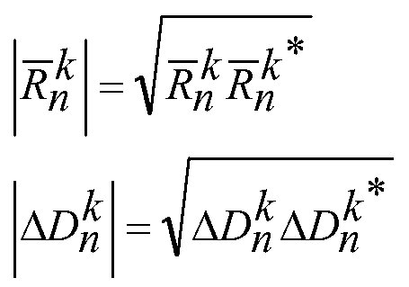
- Iterative harmonic coefficient determination block 710 determines the error in the return coefficients as
- ⁇ is a global gain value (learning rate) in the range of 0 to 1.
- Alpha, a n is the static weighting array that provides appropriate magnitude and phase scaling (vector direction) for successive reduction of the error quantity E n .
- the weighting array is the inverse of the mirror gain (transfer function) normalized to one at the primary frequency (60 Hz).
- One or more mirrors can be characterized, and the weighting array is determined from the measured transfer function.
- the linear transfer function of the mirror can be measured and learned at device startup or during operation of the device. For example, assume that a measured mirror gain (see Figure 6) at 60 Hz intervals for 17 harmonics is as follows:
- the weighting array a n (Alpha(n)) can be determined using the following algorithm:
- the MEMS transfer function can be modified by a closed loop feedback system and the composite gain of the combined system can be used to compute a n (Alpha(n)).
- the harmonic drive coefficient update shown in equation (5) and the operation of input waveform generator 712 can be performed in accordance with the following pseudocode, where Return(n) is R n , Dold(n) is D n , Dnew(n) is D n , Targ(n) is T n , and Timepts is an integer corresponding to the number of points in the ramp waveform:
- FIG 8 shows a scanning mirror slow-scan control loop that iteratively determines harmonic coefficients using an approximation of Newton's method.
- Slow-scan control loop 800 includes input waveform generator 712, digital-to- analog converter (DAC) 720, low pass filters 730 and 740, scanning mirror 732, analog-to-digital converter (ADC) 750, summing buffer 760, and fast Fourier transform (FFT) block 770, all of which are described above with respect to Figure 7.
- DAC digital-to- analog converter
- ADC analog-to-digital converter
- FFT fast Fourier transform
- Slow-scan control loop 800 also includes Newton's method harmonic coefficient determination block 810. Similar to block 710 in Figure 7, block 810 receives the return harmonic coefficients R n and targets T n , and produces harmonic drive coefficients D n .
- the Newton's method block 810 differs from block 710, in that block 810 does not receive a weighting array. Instead, block 810 adaptively modifies the learning rate of each harmonic coefficient as explained below.
- Newton's method is useful for finding successively better approximations to the zeros (or roots) of a real-valued function. As applied to the current problem, Newton's method can be shown as:
- both the fixed Alpha values and G n are used to compute new weighting coefficients at each iteration.
- Iterations may be performed on a periodic basis.
- the algorithm above may be performed once per second or once per many seconds.
- FIG. 7 and 8 may be implemented in any manner without departing from the scope of the present invention.
- any combination of hardware and/or software may be utilized, as well as any level of integration.
- a complete hardware solution is implemented.
- one or more application specific integrated circuits (ASIC) or field programmable gate arrays (FPGA) may implement most or all of the blocks shown.
- ASIC application specific integrated circuits
- FPGA field programmable gate arrays
- a processor executes instructions to perform the actions associated with Figures 7 and 8.
- Figure 9 shows a slow scan control loop that includes a digital signal processor (DSP).
- DSP 910 may be any type of processor capable of performing the actions described herein.
- DSP 910 may be a commercially available processor or may be a custom processor.
- DSP 910 may be a standalone integrated circuit or may be a "core" that is included in an ASIC.
- DSP 910 receives digitized samples from ADC 750 and provides digital data for the ramp waveform to DAC 720. DSP 910 performs the iterative harmonic coefficient adjustments according to the embodiments shown in Figure 7 or Figure 8. Specifically, DSP 910 may use a fixed weighting array to provide different learning rates for each harmonic coefficient, or DSP 910 may use adaptive learning rates for each of the harmonic coefficients.
- Memory 920 is a computer-readable medium upon which instructions are stored.
- memory 920 may be a volatile memory such as static or dynamic random access memory (SRAM or DRAM) or may be non- volatile memory such as FLASH memory.
- DSP 910 and memory 920 are included in a common integrated circuit such as an ASIC. Memory 920 may also be a medium suitable for distribution such as disk (hard, soft, compact, or otherwise) or server with downloadable files.
- DSP 910 access instructions from memory 920 and performs various method embodiments of the present invention. For example, any of the iterative harmonic coefficient determination embodiments may be performed by DSP 910. In addition, DSP 910 may characterize the response of scanning mirror 732 as described above with reference to the MirrorGain array.
- Figure 10 shows a scanning mirror slow-scan control system that includes two loops.
- the system of Figure 10 includes a low gain "inner loop” to modify the transfer function of the scanning mirror as seen by the "outer loop".
- the inner loop operates in the time domain and updates substantially in real time, whereas the outer loop operates in the frequency domain and updates more slowly.
- the inner loop is formed by summer 1012, compensator 1020, DAC 720, low pass filters 730 and 740, scanning mirror 732, ADC 750, fast-scan tone removal block 1040, additional tone removal block 1050, and gain stage 1060.
- Compensator 1020 is included to compensate for scanning mirror transfer function gain and phase characteristics, and therefore modify the transfer function of the scanning mirror as seen by the outer loop.
- Compensator 1020 may take any form, including an analog or digital filter of arbitrary order. Example compensators are described further below.
- the inner loop can include any type of compensation circuit without departing from the scope of the present invention. The type and order of compensation circuits may be determined based at least in part on the transfer function of the scanning mirror.
- compensator 1020 is implemented as an analog circuit, and DAC 720 precedes compensator 1020 in the signal path.
- the outer loop is formed by input waveform generator 712, summer 1012, compensator 1020, DAC 720, low pass filters 730 and 740, scanning mirror 732, ADC 750, summing buffer 760, FFT 770, and harmonic coefficient determination block 1010.
- Harmonic coefficient determination block may be either coefficient determination block 710 ( Figure 7) or 810 ( Figure 8).
- harmonic coefficient determination block 1010 may utilize a weighting array to determine learning rates of each harmonic coefficient, and in other embodiments, coefficient determination block 1010 may adaptively determine learning rates using an approximation to Newton's method.
- Figure 11 shows a scanning mirror slow-scan control system that includes two loops.
- the control system of Figure 11 shows a bridged-T compensator 1022 and filter 1030 in the place of compensator 1020 of Figure 10.
- Bridged-T compensators are useful for eliminating instabilities in motion control systems caused by torsional resonance. See Gregory J. Schneider, Taming Resonance in Servos, Machine Design, (Feb. 7, 1985).
- bridged-T compensator 1022 compensates for in-band mirror resonances that interfere with the slow-scan drive.
- the scanning mirror linear response shows a resonance at 795 Hz, which is within the frequency range of the harmonic drive signals.
- Bridged-T compensator 1022 is tuned to compensate for this in-band resonance, thereby reducing the gain variation that is handled by harmonic coefficient block 1010.
- Bridged-T compensator 1022 may be implemented as a finite impulse response (FIR) digital filter.
- Figure 12 shows a root locus plot showing the operation of bridged-T compensator 1022. The two scanning mirror poles cause the resonance shown at 795 Hz in Figure 6.
- the bridged-T compensator provides two poles on the real axis, and two zeros to cancel the two scanning mirror poles.
- the bridged-T zeros are superimposed directly on the scanning mirror poles, and in some embodiments, the bridged-T zeros are at the same angular offset as the scanning mirror poles.
- phase margin is increased.
- the zeros are placed on a lower angle from the real axis as the mirror poles and at a smaller radius, resulting in both a lower Q and frequency for the zeros than for the mirror poles.
- a filter 1030 follows the bridged-T compensator in the signal path.
- Filter 1030 may be a notch filter or low pass filter that is tuned to remove spectral energy at a frequency of a resonant mode outside the frequency band occupied by the harmonic drive coefficients.
- filter 1030 may be a notch filter tuned to 6.5 kHz to filter out the 6.5 kHz ancillary vibration mode ( Figure 6).
- filter 1030 may be a low pass filter having a cutoff frequency suitable to remove the unwanted spectral energy.
- Various scanning mirror designs may exhibit ancillary resonance at frequencies other than 6.5 kHz, and filter 1030 may also be tuned to remove spectral energy at these other frequencies.
- the inner loop also includes fast-scan tone removal block 1040.
- Fast-scan removal block 1040 removes spectral energy at the fast-scan frequency that results from unintentional electrical and/or mechanical crosstalk in the scanning mirror.
- Fast-scan tone removal block 1040 receives a copy of the fast-scan tone used to excite the scanning mirror on the fast scan axis.
- An example fast-scan tone removal block is shown in Figure 13.
- Figure 13 shows a least mean square (LMS) tone canceller that includes in-phase and quadrature circuits to operate on complex signal samples.
- LMS least mean square
- the in-phase circuit includes summers 1310 and 1370, multipliers 1320 and 1380, low pass filter (LPF) 1330, and a proportional/integral/derivative (PID) controller that includes a proportional block (P), an integrator block (I), and a derivative block (D).
- P proportional/integral/derivative
- the output of multiplier 1380 regenerates the I-channel of the fast-scan crosstalk present on the input signal.
- the regenerated I-channel is subtracted from the input signal to produce the I-channel output at 1312.
- the I- channel output is mixed with the I-channel fast-scan reference tone by multiplier 1320, and the result is low pass filtered by LPF 1330.
- the DC output of LPF 1330 is the error term that represents the spectral content at the fast-scan frequency.
- the PID controller operates to drive this error to zero.
- the output of the PID blocks are summed at 1370, and the result is mixed back up to the fast-scan frequency by mixer 1380 to regenerate the I-channel of the fast-scan crosstalk present on the input signal.
- the Q channel circuit operates in the same fashion as the I-channel just described.
- fast-scan tone removal block 1040 does not utilize the proportional block (P) or the derivative block (D).
- the integrator block (I) integrates the error term to arrive at the output that recreates the fast-scan tone spectral content.
- additional tone removal block 1050 may also perform tone removal for other tones.
- tone removal blocks 1040 and 1050 may include a notch filter or an LMS tone canceller.
- the LMS tone canceller imparts no phase delay and therefore preserves phase margin in the loop.
- Gain block 1060 provides gain to the inner feedback loop prior to combining the inner and outer loop data streams at 1012.
- Figures 14 and 15 show the open loop response and the closed loop response for the inner loop of Figure 11.
- the bridged-T compensator modifies the closed loop response, thereby improving loop stability.
- This improvement in loop stability i.e. phase margin
- This phase improvement occurs because it eliminates the abrupt 180 degree phase transition of the imaginary scanning mirror poles at the slow-scan frequency and introduces the slowly varying phase response of the two real poles spread over a wider frequency range.
- Figure 16 shows a combination single/dual loop slow-scan control system.
- the system shown in Figure 16 includes everything shown in Figure 10, and also includes a switch 1610.
- switch 1610 When switch 1610 is in position 1614, the system of Figure 16 operates with two loops in the same manner as the system in Figure 10.
- switch 1610 When switch 1610 is in position 1612, the inner loop is bypassed, and then the system of Figure 16 operates with a single loop similar to those shown in Figures 7 and 8.
- system of Figure 16 may operate with one loop to characterize the scanning mirror, then operate with two loops while controlling movement of the scanning mirror.
- the system of Figure 16 may also switch back and forth between the outer loop and two loops based on operating conditions.
- Mobile device 1700 may be a hand held projection device with or without communications ability.
- mobile device 1700 may be a handheld projector with little or no other capabilities.
- mobile device 1700 may be a device usable for communications, including for example, a cellular phone, a smart phone, a personal digital assistant (PDA), a global positioning system (GPS) receiver, or the like.
- PDA personal digital assistant
- GPS global positioning system
- mobile device 1700 may be connected to a larger network via a wireless (e.g., WiMax) or cellular connection, or this device can accept data messages or video content via an unregulated spectrum (e.g., WiFi) connection.
- WiMax wireless
- WiFi unregulated spectrum
- Mobile device 1700 includes scanning projection device 1701 to create an image with light 1708. Similar to other embodiments of projection systems described above, mobile device 1700 includes a projector with a scanning mirror and a slow-scan control system.
- mobile device 1700 includes antenna 1706 and electronic component 1705.
- electronic component 1705 includes a receiver, and in other embodiments, electronic component 1705 includes a transceiver.
- electronic component 1705 may be a GPS receiver.
- the image displayed by scanning projection device 1701 may be related to the position of the mobile device.
- electronic component 1705 may be a transceiver suitable for two-way communications.
- mobile device 1700 may be a cellular telephone, a two-way radio, a network interface card (NIC), or the like.
- Mobile device 1700 also includes memory card slot 1704.
- a memory card inserted in memory card slot 1704 may provide a source for video data to be displayed by scanning projection device 1701.
- Memory card slot 1704 may receive any type of solid state memory device, including for example, Multimedia Memory Cards (MMCs), Memory Stick DUOs, secure digital (SD) memory cards, and Smart Media cards.
- MMCs Multimedia Memory Cards
- SD secure digital
- Smart Media cards Smart Media cards
- Mobile device 1700 also includes data connector 1720.
- data connector 1720 can be connected to one or more cables to receive analog or digital video data for projection by scanning projection device 1701.
- data connector 1720 may mate directly with a connector on a device that sources video data.
- Figure 18 shows a flowchart in accordance with various embodiments of the present invention.
- method 1800 or portions thereof, is performed by a scanned beam projection system, embodiments of which are shown in previous figures.
- all or portions of method 1800 are performed by a hardware/software combination in an electronic system.
- Method 1800 is not limited by the particular type of apparatus performing the method.
- the various actions in method 1800 may be performed in the order presented, or may be performed in a different order. Further, in some embodiments, some actions listed in Figure 18 are omitted from method 1800.
- Method 1800 is shown beginning with block 1810 in which a scanning mirror is characterized by exciting the mirror at different frequencies and measuring a response.
- the measured response may be over any range of frequencies.
- the response may be measured over the frequency range encompassed by the slow-scan drive coefficients.
- the excitation may span a large frequency range expected to discover resonant vibration modes up to and including the fast-scan resonant vibration mode.
- the result will be a response similar to that shown in Figure 6.
- a weighting array proportional to an inverse of the scanning mirror response is determined. This corresponds to the calculation of the MirrorGain array described above.
- the weighting array is used to weight learning rates of harmonic drive coefficients in a feedback loop.
- the harmonic drive coefficients are used to produce angular displacement of the scanning mirror in the slow-scan direction. This corresponds to the operation of iterative harmonic drive coefficient determination block 710 ( Figure 7).
- a second feedback loop is operated in the time domain, the second feedback loop including compensation for a resonant vibration mode of the scanning mirror within a frequency band occupied by the harmonic drive coefficients.
- bridged-T compensator 1022 Figure 11
- the second feedback loop may also include additional filtering for other ancillary resonant vibration modes, as well as LMS adaptive tone cancelling to remove unwanted tones (e.g., fast-scan frequency tones).
- Figure 19 shows a flowchart in accordance with various embodiments of the present invention.
- method 1900 or portions thereof, is performed by a scanned beam projection system, embodiments of which are shown in previous figures.
- all or portions of method 1900 are performed by a hardware/software combination in an electronic system.
- Method 1900 is not limited by the particular type of apparatus performing the method.
- the various actions in method 1900 may be performed in the order presented, or may be performed in a different order. Further, in some embodiments, some actions listed in Figure 19 are omitted from method 1900.
- Method 1900 is shown beginning with block 1910 in which cyclical movements of a scanning mirror are detected to produce position information.
- this corresponds to a piezoresistive position sensor detecting an angular displacement of a MEMS scanning mirror.
- an FFT is performed to produce return harmonic coefficients describing frequency content of the position information.
- multiple frames of position information are averaged prior to performing the FFT.
- the return harmonic coefficients are compared with harmonic coefficient targets to obtain error values. This corresponds to comparing R n and T n as described above with reference to previous figures.
- a plurality of drive coefficients are modified responsive to the error values. Each of the plurality of drive coefficients is modified at a different rate. For example, a weighting array proportional to an inverse of a mirror response may be used to set learning rates. Also for example, a discrete approximation of Newton's method may be used to adaptively modify learning rates of the drive coefficients.
- a time domain waveform is produced from the drive coefficients. This may be performed by creating time domain waveforms for each drive coefficient and summing them, or by performing an inverse FFT, or the like.
- the time domain waveform is passed through a bridge-T compensator to compensate for a resonant mode of the mirror in a frequency band occupied by the drive coefficients, and at 1970, the scanning mirror is driven with the time domain waveform.
Landscapes
- Engineering & Computer Science (AREA)
- Physics & Mathematics (AREA)
- Power Engineering (AREA)
- General Physics & Mathematics (AREA)
- Combustion & Propulsion (AREA)
- Software Systems (AREA)
- Health & Medical Sciences (AREA)
- Artificial Intelligence (AREA)
- Computer Vision & Pattern Recognition (AREA)
- Evolutionary Computation (AREA)
- Medical Informatics (AREA)
- Electromagnetism (AREA)
- Chemical & Material Sciences (AREA)
- Automation & Control Theory (AREA)
- Optics & Photonics (AREA)
- Mechanical Optical Scanning Systems (AREA)
- Micromachines (AREA)
- Transforming Electric Information Into Light Information (AREA)
- Mechanical Light Control Or Optical Switches (AREA)
Abstract
Description



Claims
Priority Applications (3)
| Application Number | Priority Date | Filing Date | Title |
|---|---|---|---|
| CN2009801370291A CN102159982B (en) | 2008-09-22 | 2009-08-21 | Scanning mirror control |
| JP2011527863A JP5543468B2 (en) | 2008-09-22 | 2009-08-21 | Scanning mirror control |
| EP09814968.5A EP2329308B1 (en) | 2008-09-22 | 2009-08-21 | Scanning mirror control |
Applications Claiming Priority (2)
| Application Number | Priority Date | Filing Date | Title |
|---|---|---|---|
| US12/235,500 US7952783B2 (en) | 2008-09-22 | 2008-09-22 | Scanning mirror control |
| US12/235,500 | 2008-09-22 |
Publications (2)
| Publication Number | Publication Date |
|---|---|
| WO2010033342A2 true WO2010033342A2 (en) | 2010-03-25 |
| WO2010033342A3 WO2010033342A3 (en) | 2010-06-03 |
Family
ID=42037359
Family Applications (1)
| Application Number | Title | Priority Date | Filing Date |
|---|---|---|---|
| PCT/US2009/054654 Ceased WO2010033342A2 (en) | 2008-09-22 | 2009-08-21 | Scanning mirror control |
Country Status (6)
| Country | Link |
|---|---|
| US (1) | US7952783B2 (en) |
| EP (1) | EP2329308B1 (en) |
| JP (1) | JP5543468B2 (en) |
| KR (1) | KR101569706B1 (en) |
| CN (2) | CN102159982B (en) |
| WO (1) | WO2010033342A2 (en) |
Families Citing this family (33)
| Publication number | Priority date | Publication date | Assignee | Title |
|---|---|---|---|---|
| US8928880B2 (en) * | 2011-07-28 | 2015-01-06 | Honeywell International Inc. | Tuned dynamic eigen spectroscopy systems |
| TW201317624A (en) * | 2011-10-19 | 2013-05-01 | Walsin Lihwa Corp | Micro-projector, control signal for a micro-projector and method for generating the same |
| US8908092B2 (en) | 2012-03-08 | 2014-12-09 | Intersil Americas LLC | Systems and methods to improve spatial resolution on back and forth scanning display devices |
| BR112014024941A2 (en) | 2012-04-05 | 2017-09-19 | Magic Leap Inc | Active Focusing Wide-field Imaging Device |
| TW201403127A (en) * | 2012-07-13 | 2014-01-16 | Alvis Technologies Corp | Control method of a rotating mirror scanning output for projection imaging |
| US8987658B2 (en) | 2012-11-28 | 2015-03-24 | Intersil Americas LLC | Packaged light detector semiconductor devices with non-imaging optical concentrators for ambient light and/or optical proxmity sensing, methods for manufacturing the same, and systems including the same |
| JP6189137B2 (en) * | 2013-08-23 | 2017-08-30 | スタンレー電気株式会社 | Optical scanner |
| DE102013217102B4 (en) | 2013-08-28 | 2023-03-16 | Robert Bosch Gmbh | Controller for controlling a micromechanical actuator, control system for controlling a micromechanical actuator, micromirror system and method for controlling a micromechanical actuator |
| DE102013217093B4 (en) | 2013-08-28 | 2025-08-07 | Robert Bosch Gmbh | Method for adjusting the parameters of a controller for micromechanical actuators and device |
| DE102013217105B4 (en) * | 2013-08-28 | 2023-03-16 | Robert Bosch Gmbh | Controller for controlling a micromechanical actuator, control system for controlling a micromechanical actuator, micromirror system and method for controlling a micromechanical actuator |
| DE102013219567A1 (en) | 2013-09-27 | 2015-04-02 | Robert Bosch Gmbh | Method for controlling a micromirror scanner and micromirror scanner |
| JP6486102B2 (en) * | 2014-12-23 | 2019-03-20 | スタンレー電気株式会社 | Optical deflector |
| JP2016148763A (en) | 2015-02-12 | 2016-08-18 | スタンレー電気株式会社 | Picture projection device |
| US10281715B2 (en) | 2015-06-16 | 2019-05-07 | Young Optics Inc. | Imaging displacement module |
| US10145680B2 (en) * | 2016-08-12 | 2018-12-04 | Microvision, Inc. | Devices and methods for providing depth mapping with scanning laser image projection |
| JP6829375B2 (en) * | 2016-09-28 | 2021-02-10 | ミツミ電機株式会社 | Optical scanning head-mounted display and retinal scanning head-mounted display |
| US10200683B2 (en) | 2016-12-21 | 2019-02-05 | Microvision, Inc. | Devices and methods for providing foveated scanning laser image projection with depth mapping |
| US10690923B1 (en) * | 2017-06-15 | 2020-06-23 | Facebook Technologies, Llc | Scanning system for a tiling display |
| CN107555395B (en) * | 2017-09-08 | 2019-06-07 | 厦门大学 | The integrated device that optoelectronic position sensing chip is bonded with electric heating micro mirror |
| CN108594869B (en) * | 2018-01-09 | 2021-04-16 | 南京理工大学 | A micromirror control method and system based on real-time estimation of resonance point |
| US11495186B2 (en) * | 2018-05-29 | 2022-11-08 | Microsoft Technology Licensing, Llc | Synchronizing scanning display with video |
| US11004372B2 (en) * | 2018-12-11 | 2021-05-11 | Microsoft Technology Licensing, Llc | Controlling a scanning mirror system |
| US10484656B1 (en) | 2018-12-12 | 2019-11-19 | Microsoft Technology Licensing, Llc | Driver system resonant frequency determination |
| US11218506B2 (en) | 2018-12-17 | 2022-01-04 | Microsoft Technology Licensing, Llc | Session maturity model with trusted sources |
| US11487105B2 (en) | 2018-12-18 | 2022-11-01 | Microsoft Technology Licensing, Llc | Modified slow-scan drive signal |
| US10930275B2 (en) | 2018-12-18 | 2021-02-23 | Microsoft Technology Licensing, Llc | Natural language input disambiguation for spatialized regions |
| CN109696244B (en) * | 2018-12-28 | 2023-11-07 | 北京北分瑞利分析仪器(集团)有限责任公司 | Fourier transform infrared spectrometer moving mirror scanning control module based on FPGA |
| DE102019202331B4 (en) * | 2019-02-21 | 2025-09-04 | Robert Bosch Gmbh | Method for operating a MEMS system and MEMS system |
| US11039111B2 (en) * | 2019-05-23 | 2021-06-15 | Microsoft Technology Licensing, Llc | MEMS control method to provide trajectory control |
| US11108735B2 (en) | 2019-06-07 | 2021-08-31 | Microsoft Technology Licensing, Llc | Mapping subnets in different virtual networks using private address space |
| CN110794573B (en) * | 2019-10-21 | 2022-03-18 | 歌尔光学科技有限公司 | MEMS galvanometer feedback signal acquisition method, driving method and system |
| US11693231B2 (en) | 2020-07-03 | 2023-07-04 | Microsoft Technology Licensing, Llc | Disturbance rejection for laser beam scanning display |
| CN116343688A (en) * | 2021-12-25 | 2023-06-27 | 武汉万集光电技术有限公司 | MEMS micromirror, driving method, device and storage medium thereof |
Citations (1)
| Publication number | Priority date | Publication date | Assignee | Title |
|---|---|---|---|---|
| WO2005078509A2 (en) | 2004-02-09 | 2005-08-25 | Microvision, Inc. | Mems scanning system with improved performance |
Family Cites Families (6)
| Publication number | Priority date | Publication date | Assignee | Title |
|---|---|---|---|---|
| US5475291A (en) * | 1992-12-10 | 1995-12-12 | Matsushita Electric Industrial Co., Ltd. | Adjustment device for adjusting control parameters of a servo motor and an adjustment method therefor |
| JP4555905B2 (en) * | 1998-01-27 | 2010-10-06 | カール ツアイス マイクロイメージング ゲゼルシャフト ミット ベシュレンクテル ハフツング | Direction control system for scanner drive |
| US6697096B2 (en) * | 2001-11-16 | 2004-02-24 | Applied Materials, Inc. | Laser beam pattern generator having rotating scanner compensator and method |
| US6956350B2 (en) | 2002-06-14 | 2005-10-18 | Texas Instruments Incorporated | Resonant scanning mirror driver circuit |
| US6769616B2 (en) * | 2002-11-22 | 2004-08-03 | Advanced Nano Systems | Bidirectional MEMS scanning mirror with tunable natural frequency |
| JP2005080355A (en) * | 2003-08-29 | 2005-03-24 | Canon Inc | Motor driving method, optical scanning means, and display device using them |
-
2008
- 2008-09-22 US US12/235,500 patent/US7952783B2/en active Active
-
2009
- 2009-08-21 EP EP09814968.5A patent/EP2329308B1/en active Active
- 2009-08-21 KR KR1020117008400A patent/KR101569706B1/en active Active
- 2009-08-21 CN CN2009801370291A patent/CN102159982B/en active Active
- 2009-08-21 JP JP2011527863A patent/JP5543468B2/en active Active
- 2009-08-21 CN CN201210557031.8A patent/CN103149685B/en active Active
- 2009-08-21 WO PCT/US2009/054654 patent/WO2010033342A2/en not_active Ceased
Patent Citations (1)
| Publication number | Priority date | Publication date | Assignee | Title |
|---|---|---|---|---|
| WO2005078509A2 (en) | 2004-02-09 | 2005-08-25 | Microvision, Inc. | Mems scanning system with improved performance |
Non-Patent Citations (1)
| Title |
|---|
| See also references of EP2329308A4 |
Also Published As
| Publication number | Publication date |
|---|---|
| US20100073748A1 (en) | 2010-03-25 |
| EP2329308B1 (en) | 2015-11-25 |
| KR101569706B1 (en) | 2015-11-17 |
| CN102159982A (en) | 2011-08-17 |
| KR20110059640A (en) | 2011-06-02 |
| JP5543468B2 (en) | 2014-07-09 |
| US7952783B2 (en) | 2011-05-31 |
| JP2012503220A (en) | 2012-02-02 |
| CN103149685A (en) | 2013-06-12 |
| CN102159982B (en) | 2013-12-04 |
| CN103149685B (en) | 2015-04-29 |
| EP2329308A2 (en) | 2011-06-08 |
| WO2010033342A3 (en) | 2010-06-03 |
| EP2329308A4 (en) | 2014-03-12 |
Similar Documents
| Publication | Publication Date | Title |
|---|---|---|
| EP2329308B1 (en) | Scanning mirror control | |
| US7948668B2 (en) | Scanning mirror control having least mean square tone adder | |
| US20130120819A1 (en) | Scanning Projector with Non-Rectangular Display | |
| US20120281024A1 (en) | Scanning Projection Apparatus with Tangential Compensation | |
| US10382732B2 (en) | Resonant MEMS mirror parameter estimation | |
| US10303044B2 (en) | Scanning mirror control and slow scan position offset | |
| US8447138B2 (en) | Image processor, image processing method and program | |
| US20070242330A1 (en) | Tuning-Fork-Type Scanning Apparatus with a Counterweight | |
| CN102854699B (en) | The self calibration ring of the automatic focus actuator in photographing module compensates | |
| CN1138793A (en) | Equalization apparatus with effective coefficient updating operation | |
| CN102789632A (en) | Learning apparatus and method, image processing apparatus and method, program, and recording medium | |
| KR0175406B1 (en) | High resolution electronic image enlargement device and method | |
| Antonello et al. | Control of a quasi-static MEMS Mirror for raster scanning projection applications | |
| CN104698834B (en) | Regulator, control system and method, and micromirror system for controlling micromechanical actuators | |
| WO2013061570A1 (en) | Actuator drive device | |
| US20070064300A1 (en) | Methods and apparatus for controlling projectors | |
| Mollaei | Hardware implementation of adaptive filters | |
| Butterworth et al. | Adaptive-delay combined feedforward/feedback control for raster tracking with applications to AFMs | |
| JP2013181864A (en) | Synthetic aperture radar device and signal processor | |
| EP4364129A1 (en) | Closed loop controller for laser beam scanning display with high tolerance to mirror resonance frequency variation | |
| JP2009300466A (en) | Optical scanner, method of driving the same, and optical equipment | |
| CN114578546B (en) | Closed-loop position control of MEMS micromirror | |
| JP2003091841A (en) | Tracking control device | |
| McKay et al. | Using frame theoretic convolutional gridding for robust synthetic aperture sonar imaging | |
| von Grunigen et al. | An efficient feedforward frequency-domain adaptive controller for periodic sound fields |
Legal Events
| Date | Code | Title | Description |
|---|---|---|---|
| WWE | Wipo information: entry into national phase |
Ref document number: 200980137029.1 Country of ref document: CN |
|
| 121 | Ep: the epo has been informed by wipo that ep was designated in this application |
Ref document number: 09814968 Country of ref document: EP Kind code of ref document: A2 |
|
| WWE | Wipo information: entry into national phase |
Ref document number: 2011527863 Country of ref document: JP |
|
| NENP | Non-entry into the national phase |
Ref country code: DE |
|
| WWE | Wipo information: entry into national phase |
Ref document number: 2009814968 Country of ref document: EP |
|
| ENP | Entry into the national phase |
Ref document number: 20117008400 Country of ref document: KR Kind code of ref document: A |