WO2010035472A1 - 視線方向判定装置及び視線方向判定方法 - Google Patents
視線方向判定装置及び視線方向判定方法 Download PDFInfo
- Publication number
- WO2010035472A1 WO2010035472A1 PCT/JP2009/004853 JP2009004853W WO2010035472A1 WO 2010035472 A1 WO2010035472 A1 WO 2010035472A1 JP 2009004853 W JP2009004853 W JP 2009004853W WO 2010035472 A1 WO2010035472 A1 WO 2010035472A1
- Authority
- WO
- WIPO (PCT)
- Prior art keywords
- line
- coordinate
- unit
- gaze direction
- image
- Prior art date
- Legal status (The legal status is an assumption and is not a legal conclusion. Google has not performed a legal analysis and makes no representation as to the accuracy of the status listed.)
- Ceased
Links
Images


Classifications
-
- A—HUMAN NECESSITIES
- A61—MEDICAL OR VETERINARY SCIENCE; HYGIENE
- A61B—DIAGNOSIS; SURGERY; IDENTIFICATION
- A61B3/00—Apparatus for testing the eyes; Instruments for examining the eyes
- A61B3/10—Objective types, i.e. instruments for examining the eyes independent of the patients' perceptions or reactions
- A61B3/113—Objective types, i.e. instruments for examining the eyes independent of the patients' perceptions or reactions for determining or recording eye movement
-
- A—HUMAN NECESSITIES
- A61—MEDICAL OR VETERINARY SCIENCE; HYGIENE
- A61B—DIAGNOSIS; SURGERY; IDENTIFICATION
- A61B5/00—Measuring for diagnostic purposes; Identification of persons
- A61B5/16—Devices for psychotechnics; Testing reaction times ; Devices for evaluating the psychological state
- A61B5/163—Devices for psychotechnics; Testing reaction times ; Devices for evaluating the psychological state by tracking eye movement, gaze, or pupil change
-
- G—PHYSICS
- G06—COMPUTING OR CALCULATING; COUNTING
- G06T—IMAGE DATA PROCESSING OR GENERATION, IN GENERAL
- G06T7/00—Image analysis
- G06T7/60—Analysis of geometric attributes
- G06T7/68—Analysis of geometric attributes of symmetry
-
- G—PHYSICS
- G06—COMPUTING OR CALCULATING; COUNTING
- G06T—IMAGE DATA PROCESSING OR GENERATION, IN GENERAL
- G06T7/00—Image analysis
- G06T7/70—Determining position or orientation of objects or cameras
- G06T7/73—Determining position or orientation of objects or cameras using feature-based methods
-
- G—PHYSICS
- G06—COMPUTING OR CALCULATING; COUNTING
- G06V—IMAGE OR VIDEO RECOGNITION OR UNDERSTANDING
- G06V40/00—Recognition of biometric, human-related or animal-related patterns in image or video data
- G06V40/10—Human or animal bodies, e.g. vehicle occupants or pedestrians; Body parts, e.g. hands
- G06V40/18—Eye characteristics, e.g. of the iris
- G06V40/19—Sensors therefor
-
- A—HUMAN NECESSITIES
- A61—MEDICAL OR VETERINARY SCIENCE; HYGIENE
- A61B—DIAGNOSIS; SURGERY; IDENTIFICATION
- A61B5/00—Measuring for diagnostic purposes; Identification of persons
- A61B5/16—Devices for psychotechnics; Testing reaction times ; Devices for evaluating the psychological state
- A61B5/18—Devices for psychotechnics; Testing reaction times ; Devices for evaluating the psychological state for vehicle drivers or machine operators
-
- G—PHYSICS
- G06—COMPUTING OR CALCULATING; COUNTING
- G06T—IMAGE DATA PROCESSING OR GENERATION, IN GENERAL
- G06T2207/00—Indexing scheme for image analysis or image enhancement
- G06T2207/30—Subject of image; Context of image processing
- G06T2207/30196—Human being; Person
- G06T2207/30201—Face
Definitions
- the present invention relates to a gaze direction determination device and a gaze direction determination method for determining that a gaze direction of a subject is a predetermined direction.
- the detected direction needs to be expressed in an external coordinate system.
- Patent Document 1 discloses a gaze detection device that detects a state of an eyeball when a specific direction is viewed in advance and determines whether or not the specific direction is viewed from the result.
- the device described in Patent Document 1 gazes at an index in the finder and corrects a deviation between the visual axis and the eyeball axis at that time.
- Patent Document 2 discloses a driving state detection device that observes the direction of the line of sight during driving for a long time and defines the reference direction of the line of sight based on the distribution. The device described in Patent Document 2 estimates the reference position of the line of sight from time series data.
- Patent Document 1 there are two methods for the conventional gaze direction determination.
- One is to indicate or detect a gaze target and detect a gaze state (an example of an apparatus described in Patent Document 1), and the other defines the center of the gaze direction from a long-time gaze distribution (Patent Document 2).
- Patent Document 2 Device example
- Patent Document 1 requires a gaze target instruction, which is a cumbersome operation. In automatic determination, it is difficult to determine whether the user is actually looking. In any case, since measurement work in advance is necessary, the convenience cannot be improved.
- the present invention has been made in view of the above points, and can be determined immediately after the start of measurement without instructing a gaze target and prior adjustment work, and can determine the line-of-sight direction with high accuracy and accuracy.
- An object of the present invention is to provide a gaze direction determination device and a gaze direction determination method.
- the gaze direction determining apparatus of the present invention includes an imaging unit that captures a face image including both eyes, an irradiation unit that irradiates the corneas of both eyes with a light source, and a pupil of one eye of both eyes from the face image.
- a pupil detection unit that detects a first coordinate that is a central coordinate and a second coordinate that is a central coordinate of the pupil of the other eye, and a cornea reflection image of the light source in the cornea of the one eye from the face image
- a corneal reflection image detection unit that detects a third coordinate that is a central coordinate and a fourth coordinate that is a central coordinate of a corneal reflection image of the light source in the cornea of the other eye; the first coordinate and the second coordinate;
- a line symmetric position calculation is performed to calculate a vertical bisector of a first line segment connecting the line and a line symmetric position coordinate which is a position coordinate line symmetric with the third coordinate with respect to the vertical bisector.
- the coordinate distance between the fourth coordinate and the line symmetry position coordinate is calculated.
- it employs a configuration and a determining line-of-sight direction determination unit gaze direction of the both eyes.
- the gaze direction determination method of the present invention captures a face image including both eyes, irradiates the corneas of both eyes with a light source, and the first coordinates that are the center coordinates of the pupil of one eye of the both eyes from the face image. Detecting a coordinate and a second coordinate which is a central coordinate of the pupil of the other eye, and from the face image, a third coordinate which is a central coordinate of a cornea reflection image of the light source in the cornea of the one eye; The fourth coordinate which is the center coordinate of the cornea reflection image of the light source in the cornea of the other eye is detected, and the perpendicular bisector of the first line segment connecting the first coordinate and the second coordinate is calculated.
- the corneal reflection image of the left eye or the right eye is in a line-symmetric position with respect to the center line of the left and right eye pupils, and the line-of-sight direction at a specific position is determined from the determination result.
- the determination result is highly reliable, and the gaze direction can be determined with higher accuracy compared to a method of performing statistical processing. For the same reason, it is possible to guarantee that the determined line-of-sight direction is an accurate line-of-sight direction, so that it is not necessary to measure for a long time as in the conventional example.
- the determination can be made immediately from the captured image, the determination can be made immediately after the measurement is started.
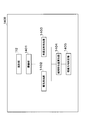
- FIG. 1 The block diagram which shows the structure of the gaze direction determination apparatus which concerns on Embodiment 1 of this invention.
- FIG. The flowchart which shows the gaze direction determination process of the gaze direction determination apparatus which concerns on the said Embodiment 1.
- FIG. The figure which shows the example of the input image input into the gaze direction determination apparatus which concerns on the said Embodiment 1.
- FIG. The figure which shows the example of the image feature used with the gaze direction determination apparatus which concerns on the said Embodiment 1.
- FIG. The block diagram which shows the structure of the gaze direction determination apparatus which concerns on Embodiment 2 of this invention.
- the flowchart which shows the gaze direction determination process of the gaze direction determination apparatus which concerns on the said Embodiment 2.
- FIG. The block diagram which shows the structure of the gaze direction determination apparatus with an automatic calibration function which concerns on Embodiment 3 of this invention.
- FIG. The figure explaining that the gaze direction offset of the gaze direction determination apparatus with an automatic calibration function according to the third embodiment can be automatically corrected.
- FIG. 4 The block diagram which shows the structure of the gaze direction determination apparatus which concerns on Embodiment 4 of this invention.
- FIG. The figure which shows the positional relationship of the cornea reflection image and cornea projection image of the gaze direction determination apparatus which concerns on the said Embodiment 4.
- the present invention detects a pupil or the center of a pupil and a cornea reflection image of illumination from a face image acquired by an imaging device including an illuminating unit, and determines a gaze direction of a subject from their line symmetry
- the present invention relates to a determination device.
- the line-of-sight direction determination means determining whether or not the subject's line of sight faces a specific direction.
- the specific direction is not necessarily one, and may be a plurality of directions.
- the pupil or the center of the pupil and the corneal reflection image of the illumination are detected from the face image acquired by the imaging device including the illumination means, and the line of sight of the subject is determined based on their line symmetry.
- a line-of-sight direction determination apparatus for determining a direction will be described.
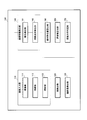
- FIG. 1 is a block diagram showing a configuration of a gaze direction determining apparatus according to Embodiment 1 of the present invention.
- This embodiment is provided in the interior of an automobile, detects the direction of the driver's line of sight, and gives a warning when the front is not turned for a long time. This is an example of applying.
- the line-of-sight direction determination apparatus 100 is, for example, an information presentation device such as a car navigation system, a television, or a speaker, a safety state monitoring device such as a driver support camera or a monitoring camera, a video image such as a still camera or a video camera
- an information presentation device such as a car navigation system, a television, or a speaker
- a safety state monitoring device such as a driver support camera or a monitoring camera
- a video image such as a still camera or a video camera
- the present invention can be applied to devices that require information on where an operator or a non-photographer is looking, such as a recording device or a life assist device such as a robot.
- the gaze direction determination apparatus 100 includes an image input unit 110, a face detection unit 120, a face part detection unit 130, an image feature detection unit 140, a line symmetry position calculation unit 150, an evaluation value calculation unit 160, and a gaze direction determination unit 170. Configured.
- the image input unit 110 outputs the image captured by the imaging unit 111 to the face detection unit 120 described later.
- the image input unit 110 is installed in front of the driver's seat, such as on the steering wheel of a car or on the dashboard, and is installed at a position where the driver can shoot, and an irradiation unit that irradiates the driver's face 112, and a synchronization unit 113 that synchronizes the imaging unit 111 and the irradiation unit 112.
- the imaging unit 111 includes an image sensor such as a CCD (Charge Coupled Devices) or a CMOS (Complementary Metal Oxide Semiconductor), and acquires an image in accordance with a synchronization signal input from the synchronization unit 113.
- an image sensor such as a CCD (Charge Coupled Devices) or a CMOS (Complementary Metal Oxide Semiconductor), and acquires an image in accordance with a synchronization signal input from the synchronization unit 113.
- the captured face image will be described below assuming that one pixel is one coordinate point with the horizontal direction of the image as the X axis and the vertical direction of the image as the Y axis.
- the irradiation unit 112 is invisible, but the imaging unit 111 includes a near-infrared LED having sensitivity, and emits light in accordance with a synchronization signal from the synchronization unit 113.
- the synchronization unit 113 outputs a synchronization signal to the imaging unit 111 and the irradiation unit 112 for a time corresponding to the time from the start to the end of exposure of the imaging unit 111.
- the face detection unit 120 detects a face image, which is a human face image, from the image input from the image input unit 110, and outputs the face image to the face part detection unit 130.
- the face part detection unit 130 detects face parts such as the corners of the eyes, the eyes, the center of the eyes, the nostrils, the corners of the mouth, and both ends of the eyebrows from the face image input from the face detection unit 120, and forms a plurality of contours of each face part.
- the coordinates of the point are output to the image feature detection unit 140.
- the image feature detection unit 140 includes a pupil detection unit 141 that detects a pupil from a face image, and a corneal reflection image detection unit 142 that detects a reflection image of the irradiation unit 112 on the cornea from the face image.
- the cornea reflection image represents a reflection image of the cornea surface called a Purkinje image.
- the pupil detection unit 141 detects the left and right eye pupils from the face image input by the image input unit 110 and the face component coordinates input by the face component detection unit 130, and the center coordinates of the left and right pupils are line-symmetrical positions. The result is output to the calculation unit 150.
- the cornea reflection image detection unit 142 detects a cornea reflection image of the irradiation unit 112 of the left and right eyes from the face image input by the image input unit 110 and the face component coordinates input by the face component detection unit 130.
- the center coordinates of the left and right corneal reflection images are output to the line symmetry position calculation unit 150.
- the line symmetry position calculation unit 150 calculates the line symmetry position of the left and right eye cornea reflection image center from the pupil center coordinates of the left and right eyes input from the image feature detection unit 140 and the cornea reflection image center coordinates, The line symmetric position coordinates and the corneal reflection image center coordinates of the other eye are output to the evaluation value calculation unit 160, respectively.
- Line symmetry means line symmetry with respect to a vertical bisector with a line segment having the left and right pupil centers as endpoints.
- the evaluation value calculation unit 160 determines the line symmetry of the corneal reflection image from the projection coordinates input from the line symmetry position calculation unit 150, the corneal reflection image center coordinates and the line symmetry position coordinates input from the image feature detection unit 140. A line symmetry evaluation value to be evaluated is calculated and output to the line-of-sight direction determination unit 170.
- the line-of-sight direction determination unit 170 determines the line symmetry of the left-right corneal reflection image from the line-symmetry evaluation value input from the evaluation value calculation unit 160. If it is determined that the camera is facing, or if there is no line symmetry, it is determined that the camera is not facing, and the determination result is output to an alarm device (not shown). An alarm device (not shown) issues an alarm when the result of the determination is that the camera is not facing the camera for a long time.
- This warning is a display including a warning message, a voice message by a voice synthesis LSI, LED light emission, sound emission by a speaker, or a combination thereof.
- the line-of-sight direction determination apparatus 100 includes a CPU that is a control unit, a ROM that stores a control program, a RAM for executing a program, a camera that is an imaging device, and a display unit that is a display / alarm device.
- the control unit controls the operation of each unit of the line-of-sight direction determination apparatus 100.
- Each unit in FIG. 1 is clearly shown as a block for performing a gaze direction determination process executed by the control unit.
- FIG. 2 to 4 are diagrams for explaining a gaze direction determination method of the gaze direction determination apparatus 100.
- FIG. 2 to 4 are diagrams for explaining a gaze direction determination method of the gaze direction determination apparatus 100.
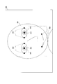
- the projector 201 in FIG. 1, the irradiation unit 112 irradiates the eyeball 203 of the face 202.
- the camera 206 (the imaging unit 111 in FIG. 1) acquires a cornea reflection image 205 reflected from the cornea 203a of the eyeball 203.
- a cornea reflection image 205 appears on the cornea 203 a of the eyeball 203 by light irradiation from the projector 201.
- the gaze direction determination apparatus 100 detects the cornea reflection images 205 of the left and right eyes using the left-right symmetry of the face. That is, the positions of the corneal reflection images 205 of the left and right eyes are calculated, and it is determined whether or not the obtained corneal reflection image position is a line-symmetric position between the left and right eyes.
- the cornea reflection image 205 of the projector 201 is acquired by the left and right eyes, and the time when the projector 201 is viewed from the symmetry of the reflected image position 205 with respect to the pupil 204 is detected. Further, by verifying the left-right symmetry of the corneal reflection image position of the projector 201, it is determined whether or not the camera 206 is viewed.
- the position of the cornea reflection image 205 is symmetrical.
- the position of the corneal reflection image 205 is asymmetrical.
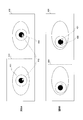
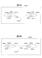
- FIG. 5 is a diagram for explaining a gaze direction determination algorithm
- FIG. 5A shows a face image
- FIG. 5B is calculated based on the face image and the face image. 2 shows a perpendicular bisector of a line segment connecting the pupils of both eyes.
- the eyeball 203 is detected from the face image 202, and the pupil 204 and the corneal reflection image 205 of both eyes are detected.
- this algorithm projects one reflection image at a position symmetrical with respect to the vertical bisector 211 of the left and right pupils.
- the other cornea reflection image 205 projected on one eyeball 203 is referred to as a cornea projection image 215.
- the cornea reflection image 205 of the right eye is projected to the left eye, and the cornea reflection image 205 of the left eye and the projected cornea projection image 215 are arranged close to each other on the left eye.
- This algorithm detects a deviation between the cornea reflection image 205 of the left eye and the projected cornea projection image 215. If this deviation amount is less than or equal to the threshold, the direction of the line of sight at that time is determined as the camera direction.
- the means for realizing this algorithm will be described later with reference to the gaze direction determination processing flow of FIG.
- the direction of the line of sight can be determined by verifying whether or not the coordinate positions of the cornea reflection images of both eyes are line-symmetric with respect to the vertical bisector 211.
- FIG. 6 is a flowchart showing the gaze direction determination process of the gaze direction determination device 100.
- FIG. 7 is a diagram illustrating a face image input to the line-of-sight direction determination apparatus 100.
- the image input unit 110 starts photographing work by the start of this program.
- the start of the photographing operation may be performed manually, or may be performed by the visual line direction determination device 100 using an external signal as a trigger.
- step S ⁇ b> 1 the image input unit 110 acquires the face image 300 of FIG. 7 from the imaging unit 111 synchronized with the irradiation unit 112 by the synchronization unit 113 at regular intervals, and uses the face image 300 as the face detection unit 120. Output to.
- the image input unit 110 is assumed to be a sensor composed of a digital camera equipped with a CMOS image sensor and a lens and a projector equipped with a near-infrared LED, whereby a PPM (Portable Pix) photographed in synchronization with the projector.
- An image or the like in the “Map file format” format is temporarily stored in an image storage unit (for example, a memory space of a PC) existing in the image input unit 110.
- the temporarily stored image is input to the face detection unit 120 in the PPM format.
- the irradiation unit 112 is a synchronous pulse-driven near-infrared LED projector that lights up in synchronization with the exposure time of the imaging unit 111.
- the irradiation unit 112 may be always lit instead of synchronous pulse drive.
- step S ⁇ b> 2 the face detection unit 120 performs a face area 301 detection process from the face image 300 input by the image input unit 110.
- an image that is a feature is extracted from an input image, and the extracted image that is a feature is compared with a feature image that represents a face area that is prepared in advance. Is detected.
- the Gabor feature amount of the average face acquired in advance is compared with the Gabor feature amount extracted by scanning the input image, and the reciprocal of the absolute value of the difference is used.
- the face area is searched from the image for the area having the highest correlation in the face area 301 of FIG. 7 as compared with the template prepared in advance.
- the face area 301 may be detected by detecting a skin color area from the image, performing ellipse detection, or using a statistical pattern identification method. In addition, any method may be used as long as it can perform the face detection.
- step S3 the face part detection unit 130 uses the face region 301 of the face image 300 input by the face detection unit 120 as a search region, and performs a process of detecting a face part group 302 such as a mouth corner, an eye corner, and an eye.
- a face part group 302 such as a mouth corner, an eye corner, and an eye.
- Face part group detection uses, for example, a separability filter to detect two-dimensional coordinates such as the end points of facial parts such as the corners of the mouth, the corners of the eyes, and the eyes and the nostrils.
- the learning device learns the relationship between a plurality of face images and the position of the facial part corresponding to the facial image in advance, and the facial image 300 is input to the learning device, the place with the highest likelihood is used as the facial part. It may be detected, or a facial part may be searched from the facial image 300 using a standard facial part template.
- step S4 the pupil detection unit 141 detects the center coordinates of the pupil 303 in FIG. 3 from the eye region detected by the face part group detection in step S3.
- the center coordinate of the pupil is, for example, a circle having the highest luminance separation degree by applying a circular separation degree filter to the eye area including the corners of the eyes and the eyes detected by the face part group detection in step S3.
- the center coordinates are extracted as the center coordinates of the pupil.
- the luminance sum may be taken in the horizontal and vertical directions, and the center of the pupil may be the point where the luminance sum taken in the vertical direction and the luminance sum taken in the horizontal direction are small.
- the detection target may be not the pupil but the center of the iris or the center of the cornea.
- Any other detection method may be employed as long as it can detect the center coordinates of the pupil.
- step S5 the corneal reflection image detection unit 142 detects the center coordinates of the corneal reflection image 304 in FIG. 7 from the eye area detected by the face part group detection in step S3.
- a luminance histogram is calculated for the peripheral region around the center of the pupil detected in step S4, and the center of gravity of the coordinates of the maximum luminance pixel is detected as the central coordinate of the corneal reflection image. Is done.
- the centroids of pixels in the upper few% (for example, 1%) of the histogram may be acquired.
- the determination process is stopped, and the process returns to step S1.
- the number of pixels having the maximum luminance is larger than a predetermined threshold, it is assumed that the reflection of the object other than the irradiation unit 112 is included in the cornea reflection image, and the process is stopped and the process returns to step S1. .
- step S ⁇ b> 6 the line symmetry position calculation unit 150 calculates a vertical bisector that connects the center coordinates of the pupil 303 input from the image feature detection unit 140 and the center coordinates of the cornea reflection image 304. The center coordinates of the line symmetry position of the left and right corneal reflection image with respect to the calculated vertical bisector are calculated.
- FIG. 8A and 8B are diagrams illustrating examples of image features used in the line-of-sight direction determination apparatus 100.
- FIG. 8A illustrates an image 410 when the line of sight faces the direction of the camera 206, and
- FIG. The image 420 when not facing the direction of is shown.
- the pupil 411 is the same as the pupil 303 in FIG. 7, and the corneal reflection image 412 is the same as the corneal reflection image 304 in FIG.
- the line symmetry position calculation unit 150 calculates a vertical bisector 414 that connects the center coordinates of the pupils 411 of both eyes according to the following equation (1).
- the coordinates of the right eye pupil are (xr, yr), and the coordinates of the right eye pupil are (xl, yl).
- Expression (2) is an expression representing the line symmetry position of the center coordinates of the cornea reflection image of the right eye, and the coordinates of the line symmetry position are represented by (xs, ys).
- a and b shall be respectively represented by following Formula (3).
- step S ⁇ b> 7 the evaluation value calculation unit 160 calculates the left and right corneal reflection image position from the center coordinates of the corneal reflection image 304 input from the image feature detection unit 140 and the line symmetry position input from the line symmetry position calculation unit 150.
- the line symmetry is calculated as a line symmetry evaluation value V expressed by the following equation (4).
- the line symmetry position 424 of the left and right corneal reflection images is the other side. Since the position is close to the cornea reflection image, the line symmetry evaluation value V takes a large value.
- the line symmetric position 422 of the left and right corneal reflection images is the other corneal reflection image. Since the position is far from 421, the line symmetry evaluation value takes a small value.
- the line symmetry evaluation value V is not necessarily a value represented by the formula (4), and is higher as the line symmetry position 422 of the left and right corneal reflection images and the other corneal reflection image 421 are closer. Any evaluation value that returns a value may be used.
- step S8 the line-of-sight direction determination unit 170 determines whether the line-of-sight direction is a specific direction from the line symmetry evaluation value input from the evaluation value calculation unit 160. For example, if the line symmetry evaluation value is equal to or greater than a predetermined threshold, it is determined that the user is facing a specific direction.
- an evaluation value for a certain time may be recorded, and when the average value is equal to or greater than a threshold value, it may be determined that the user is facing a specific direction.
- the specific direction represents the direction of the image input unit 110.
- Any other determination method may be adopted as long as it is a technique capable of performing the above-described line-of-sight direction determination.
- step S9 when it is determined by the line-of-sight direction determination unit 170 that the line-of-sight determination unit 170 determines that the line of sight does not face the front direction, the alarm count that indicates the number of times that the line-of-sight is determined not to face the front is increased by one. At this time, if N exceeds a predetermined threshold, it is assumed that the front is not seen for a long time and an alarm is issued.
- the alarm count is set to zero. Note that the alarm count is zero in the initial state.
- step S10 end determination is performed.
- the end determination may be performed by manually inputting an end command, or may be performed by the line-of-sight direction determination device 100 using an external signal as a trigger.
- step S10 the process returns to step S1.
- the line-of-sight direction determination apparatus 100 determines that the corneal reflection image of the left eye or the right eye is in a line-symmetric position with respect to the center line of the left and right eye pupils.
- the calculation is performed with only one eye. Also, when both eyes are used, they are only used for stabilizing the line of sight, and there is no example used for detecting the line of sight in a specific direction as in this embodiment. Furthermore, in the conventional example, when it is attempted to detect the gaze direction in a specific direction, it is necessary to instruct or detect the gaze target and to estimate from the statistics of the detection results for a long time. With this, it is possible to determine the line-of-sight direction accurately and accurately.
- the corneal reflection image of the left eye or the right eye is in a line-symmetric position with respect to the center line of the left and right pupils.
- a pupil and a cornea reflection image have the characteristic which can be detected stably also from a low-resolution picked-up image, and can determine a gaze direction stably.
- the left-right symmetry of the cornea reflection image exists without individual differences, no prior adjustment work is required and it can be easily used.
- the determination can be made with only one image, the determination can be made immediately after the start of measurement, and the determination can be made even in a situation where a specific direction is viewed for a moment.
- an evaluation value calculation 160 that calculates an evaluation value that represents the line symmetry of the left and right corneal reflection images is provided, and the line-of-sight direction determination unit 170 first determines the left and right corneal reflection images based on the evaluation values. Is determined, and then a specific gaze direction is determined. Therefore, it is possible to determine the gaze direction with higher accuracy.
- FIG. 9 is a block diagram showing the configuration of the gaze direction determining apparatus according to Embodiment 2 of the present invention. In the description of the present embodiment, the same components as those in FIG.
- This embodiment is provided in the interior of an automobile, detects the direction of the driver's line of sight, and gives a warning when the front is not turned for a long time. This is an example of applying.
- the line-of-sight direction determination apparatus 500 takes an example of a case where it is determined whether or not the line of sight faces the midpoint of the camera and the projector when the face faces the midpoint direction of the camera and the projector.
- the line-of-sight direction determination apparatus 500 includes an image input unit 110, a face detection unit 120, a face part detection unit 130, an image feature detection unit 140, a line symmetry position calculation unit 150, an evaluation value calculation unit 160, a face direction calculation unit 501, and a face A line-of-sight direction determination unit 502 is provided.
- the face direction calculation unit 501 calculates face direction information from the face part position input from the face part detection unit 130 and outputs the face direction information to the face gaze direction determination unit 502.
- the face line-of-sight direction determination unit 502 determines the line symmetry of the left-right corneal reflection image from the line symmetry evaluation value input from the evaluation value calculation unit 160. It is determined that the line-of-sight direction is facing the midpoint direction of the camera and the projector, and if there is no line symmetry, it is determined that the camera and the projector are not facing the midpoint direction, and an alarm (not shown) is shown. Output to the device.
- FIG. 10 is a flowchart showing the gaze direction determination process of the gaze direction determination device 500. Portions that perform the same processing as the flow shown in FIG. 6 are assigned the same step numbers, and descriptions of overlapping portions are omitted.
- step S7 when the evaluation value calculation unit 160 calculates the line symmetry evaluation value, the process proceeds to step S21.
- step S ⁇ b> 21 the face direction calculation unit 501 calculates face direction information from the face part group 302 input from the face part detection unit 130.
- the face direction information when the face part position is input in three dimensions, for example, the normal vector of the plane on which the left and right corners of the eye and the midpoint of the mouth corner are obtained as the face direction vector. Further, when the face part position is input in two dimensions, for example, the posture of a standard head three-dimensional model is estimated from the distribution of the face part group 302. The normal vector of the plane to be placed is acquired as the face direction vector.
- the face line-of-sight direction determination unit 502 first determines from the face direction information input from the face direction calculation unit 501 whether or not the face direction faces the midpoint between the camera and the projector.
- the determination method for example, a vector connecting the center of the camera and the center of the projector is calculated from the center of the camera measured in advance and the center of the projector, and an inner product of the horizontal component of the face direction vector is obtained.
- the inner product value is 0, it is determined that the face direction is facing the midpoint between the camera and the projector. However, the inner product value may include an error, and is not necessarily exactly 0. At this time, if it is not determined that the face direction is facing the midpoint between the camera and the projector, it is determined that the line-of-sight direction is not a specific direction.
- the face gaze direction determination unit 502 determines whether the gaze direction is a specific direction from the line symmetry evaluation value input from the evaluation value calculation unit 160. For example, if the line symmetry evaluation value is equal to or greater than a predetermined threshold, it is determined that the user is facing a specific direction. Alternatively, an evaluation value for a predetermined time may be recorded, and when the average value is equal to or greater than a threshold value, it may be determined that the user is facing a specific direction.
- the specific direction represents, for example, the middle point direction of the camera and the projector.
- Any other determination method may be adopted as long as it is a technique capable of performing the above-described line-of-sight direction determination.
- the gaze direction determination device 500 includes the face direction calculation unit 501 that calculates the face direction information, and the face gaze direction determination unit 502 first determines that the face is between the camera and the projector. If it is pointing to a point (it is only an example and may be at an arbitrary position), the same gaze direction determination process as in the first embodiment is continued, and if it is not facing, the process ends. Thereby, not only the line-of-sight direction but also the face direction can be included in the determination operation. For example, it can be detected that the driver's face is facing the front. This information can be output to the alarm device when the driver does not face the front for a long time, and the alarm device can issue an alarm.
- Embodiment 3 is an application example of a gaze direction detection device with an automatic calibration function, which has a function of automatically correcting a detection error of the gaze direction detection device.
- the gaze direction is calculated using the positions of facial parts such as the corners of the eyes, the eyes, the eyebrows, and the nostrils, and the position of the pupil.
- the face part is detected by deviating from the true value, or the eye model necessary for calculating the eye direction has an error with respect to the actual eye shape.
- a quantitative deviation occurs.
- Embodiment 3 enables this calibration work to be performed automatically.
- the line-of-sight detection devices 100 and 500 of the first and second embodiments detect when the line of sight is facing the camera direction, and compare with the detection results of the line-of-sight direction detection devices 100 and 500 at that time. , Correct the deviation.
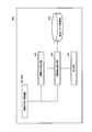
- FIG. 11 is a block diagram showing a configuration of a gaze direction determining apparatus with an automatic calibration function according to Embodiment 3 of the present invention.
- the gaze direction detection device 600 with the automatic calibration function includes a gaze direction determination device 100, a gaze direction calculation unit 610 that calculates the gaze direction from the face image, and the detection result of the gaze direction calculation unit 610.
- a line-of-sight detection calibration unit 620 that calibrates (corrects) the deviation from the value
- a calibration parameter storage unit 630 that stores parameters of the calibration result
- an output unit 640 that outputs the result of the line-of-sight detection.
- the line-of-sight direction determining apparatus 100 of the first embodiment is used, but the line-of-sight direction determining apparatus 500 of the second embodiment may be used instead of the line-of-sight direction determining apparatus 100.
- the gaze direction determination apparatus 100 determines that the gaze direction is facing the camera direction, and acquires the determination result as gaze direction determination information. Further, the image input unit 110 (see FIG. 1) of the gaze direction determination apparatus 100 outputs the face image to the gaze direction calculation unit 610 and outputs the gaze direction determination information to the gaze direction calibration unit 620.
- the gaze direction calculation unit 610 calculates the gaze direction from the face image input from the image input unit 110 of the gaze direction determination device 100 and outputs the gaze direction information to the gaze detection calibration unit 620 as gaze direction information.
- the line-of-sight detection calibration unit 620 calculates a calibration parameter P from the line-of-sight direction determination information input from the line-of-sight direction determination device 100 and the line-of-sight direction information input from the line-of-sight direction calculation unit 610, and the calibration parameter is stored in the calibration parameter storage unit. Input to 630. Further, the line-of-sight detection calibration unit 620 acquires calibrated line-of-sight direction information from the line-of-sight direction information input from the line-of-sight direction calculation unit 610 and the calibration parameter P.
- the calibration parameter P will be described later with reference to the flowchart of FIG.
- the calibration parameter storage unit 630 stores the calibration parameter P input from the line-of-sight detection calibration unit 620, and outputs the calibration parameter P to the line-of-sight direction calculation unit 610 via the line-of-sight detection calibration unit 620.
- the output unit 640 outputs the calibrated gaze direction information input from the gaze detection calibration unit 620 using sound, video, symbols, characters, and the like.
- FIG. 12 is a flowchart showing the operation of the gaze direction detecting device 600 with an automatic calibration function.
- the line-of-sight direction determination apparatus 100 starts photographing work.
- the start of the photographing operation may be performed manually, or may be performed by the visual line direction determination device 100 using an external signal as a trigger.
- the gaze direction calculation unit 610 calculates the gaze direction.
- the gaze direction information is acquired as the gaze direction vector Ve.
- the gaze detection method employs the following method. a. In the gaze direction detection, the gaze direction is calculated from the corner of the eye and the eye detected by the face component detection unit 190 and the center of the pupil detected by the pupil detection unit 141 as follows. b. First, the center position of the eyeball is estimated from the positions of the corners of the eyes and the eyes. For example, it is assumed that the center of the eyeball is located at a predetermined distance in the normal direction of a line segment connecting the corners of the eyes and the eyes. c.
- a statistical method may be adopted in which the positions of the center of the eyeball with respect to the corners of the eyes and the eyes are measured in advance for a large number of subjects and the average is taken. d. Next, a straight line connecting the estimated eyeball center and pupil center is calculated. e. Finally, a direction vector of the straight line is calculated, and this is acquired as a line-of-sight direction vector.
- any calculation method may be employed as long as it is a technique capable of performing the above gaze direction calculation.
- step S32 the line-of-sight direction determination apparatus 100 determines whether or not the line-of-sight direction faces the camera direction by the method described in the first embodiment.
- step S33 When it is determined that the line-of-sight direction is facing the camera direction, the process proceeds to step S33.
- step S35 When it is determined that the line-of-sight direction does not face the camera direction, the process proceeds to step S35.
- the gaze detection calibration unit 620 calculates a calibration parameter P for gaze direction calculation.
- the calibration parameter P is represented by, for example, an angle between the line-of-sight direction vector Ve calculated in step S31 and the line-of-sight direction vector Vc when the line of sight faces the camera direction.
- the calibration parameter P is calculated by the following equation (5).
- step S34 the calibration parameter storage unit 630 stores the calibration parameter P. At this time, the past calibration parameter P is discarded, and only the newest calibration parameter P is stored.
- step S35 the line-of-sight direction calibration unit 620 calibrates the line-of-sight direction information from the calibration parameter P, and obtains it as calibrated line-of-sight direction information.
- the calibrated gaze direction information is expressed by a calibrated gaze direction vector Vf.
- the gaze direction information is calibrated by the following equation (6).
- Rot (P) is a rotation matrix that is rotated by an angle corresponding to the calibration parameter P.
- step S36 the output unit 640 outputs corrected gaze direction information.
- step S37 end determination is performed.
- the end determination may be performed manually or by some automatic trigger.
- step S37 the process returns to step S31.
- FIG. 13 is a diagram for explaining that the gaze direction offset (quantitative deviation from the true value) can be automatically corrected.
- the gaze direction determining apparatus 100 can acquire a cornea reflection image of the projector 201 with the left and right eyes, and can detect in real time when the projector direction is viewed from the symmetry of the reflected image position 205 with respect to the pupil 204. As a result, as shown in FIG. 13B, it is possible to automatically correct the offset in the line-of-sight direction and realize high-precision line-of-sight detection.
- FIG. 14 is a block diagram showing a configuration of a gaze direction determining apparatus according to Embodiment 4 of the present invention.
- the face image will be described assuming that one pixel is one coordinate point with the horizontal direction of the image as the X axis and the vertical direction of the image as the Y axis.
- the gaze direction determination device 1400 includes an irradiation unit 112, an imaging unit 1401, a pupil detection unit 1402, a cornea reflection image detection unit 1403, a line symmetry position calculation unit 1404, and a gaze direction determination unit. 1405.
- the irradiation unit 112 irradiates the cornea of both eyes of the driver with a light source, and the imaging unit 1401 captures a face image including both eyes irradiated with the light source.
- the irradiation unit 112 has a light source as described in the first embodiment.
- the irradiation unit 112 emits light at least from the start to the end of exposure of the imaging unit 1401. The positional relationship between the irradiation unit 112 and the imaging unit 1401 will be described later.
- the imaging unit 1401 includes an image sensor such as a CCD or a CMOS, and acquires a face image including both eyes. Note that the imaging unit 1401 is installed on the front upper side or the lower front side with respect to the center point of the line segment that connects the pupils of both eyes when the driver's line of sight faces the traveling direction of the vehicle. In other words, when the driver's line of sight faces the traveling direction of the car, the driver's line of sight is facing the vertical direction of the imaging unit 1401.
- an image sensor such as a CCD or a CMOS
- the pupil detection unit 1402 calculates the center coordinates of the pupil based on the face image captured by the imaging unit 1401, and the corneal reflection image detection unit 1403 has the irradiation unit 112 based on the face image acquired by the imaging unit 1401. The center coordinates of the cornea reflection image in the cornea of the light source are calculated.
- the line symmetric position calculation unit 1404 is based on the center coordinates of the pupils of both eyes and the center coordinates of the cornea reflection images of both eyes, and the vertical bisection of the line segment connecting the center coordinates of the left eye pupil and the center coordinates of the right eye pupil. The coordinates of the line symmetry position of the cornea reflection image of one of the eyes with respect to the segment are calculated.
- the line-of-sight direction determination unit 1405 determines the line-of-sight direction of the driver based on the distance between the center coordinates of the cornea reflection image of the other eye of both eyes and the coordinates of the line symmetry position.
- FIG. 15 is a diagram illustrating a positional relationship between both eyes, the irradiation unit 112, and the imaging unit 1401
- FIG. 15A shows a bird's-eye view of both eyes
- FIG. 15B shows a front view of both eyes
- 15C shows a side view of both eyes, the irradiation unit 112, and the imaging unit 1401.
- the imaging unit 1401 is a position where both eyes can be imaged
- the irradiation unit 112 is premised on a position where the corneas of both eyes can be irradiated by a light source.
- a line segment 1505 connecting the center of the right eye pupil 1501 and the center of the left eye pupil 1502 is obtained.
- the orientation of the imaging unit 1401 and the irradiation unit 112 is perpendicular to the line segment 1505 that connects the center of the right eye pupil 1501 and the center of the left eye pupil 1502.
- FIG. 15B As shown in C, a line segment 1509 that connects the foot 1511 of the perpendicular 1508 of the imaging unit 1401 to the plane 1506 including the line segment 1505 and the foot 1510 of the perpendicular 1507 of the irradiation unit 112 to the plane 1506 is perpendicular to the line 1507.
- a bisector As shown in C, a line segment 1509 that connects the foot 1511 of the perpendicular 1508 of the imaging unit 1401 to the plane 1506 including the line segment 1505 and the foot 1510 of the perpendicular 1507 of the irradiation unit 112 to the plane 1506 is perpendicular to the line 1507.
- a bisector As shown in C, a line segment 1509 that connects the foot 1511 of the perpendicular 1508 of the imaging unit 1401 to the plane 1506 including the line segment 1505 and the foot 1510 of the perpendicular 1507 of the irradiation unit 112 to the plane 1506 is perpendicular
- the plane 1506 has been described as being perpendicular to the pupil 1501 of the right eye, but this is not restrictive. That is, even when the plane 1506 has an arbitrary angle with respect to a plane perpendicular to the pupil 1501 of the right eye, the relationship between the perpendicular line 1507 and the perpendicular line 1509 may be as described above.
- the distance from the imaging unit 1401 to the line segment 1505 has been described as being closer than the distance from the irradiation unit 112 to the line segment 1505, but is not limited thereto. That is, in the bird's eye view, the distance from the imaging unit 1401 to the line segment 1505 may be longer than or the same as the distance from the irradiation unit 112 to the line segment 1505.
- the imaging unit 1401 and the irradiation unit 112 are described as being positioned below the line-of-sight direction of the right eye pupil 1501, but one or both of the imaging unit 1401 and the irradiation unit 112 are positioned above. May be.
- the irradiating unit 112 has a line segment connecting a leg of a perpendicular line to a plane including a line segment connecting the pupils of both eyes from the imaging unit 1401 and a leg of a perpendicular line from the irradiating unit 112 to the plane. It is installed so as to be perpendicular to the line connecting the pupils.
- the pupil detection unit 1402 detects the pupils of both eyes from the face image acquired by the imaging unit 1401, and calculates the center coordinates of the pupils of both eyes. Specifically, the pupil detection unit 1402 applies a circular separability filter to both eyes included in the face image to detect a circle with the highest luminance segregation as a pupil, and the center of the pupil in the face image Calculate the coordinates.
- the cornea reflection image detection unit 1403 detects a cornea reflection image in the cornea of the light source of the irradiation unit 112 from the face image acquired by the imaging unit 1401, and calculates center coordinates of the left and right cornea reflection images.
- the cornea reflection image is a reflection image of the light source generated in the cornea when the light source is reflected on the cornea.
- the cornea reflection image detection unit 1403 calculates a luminance histogram for the face image, detects the center of gravity of the pixel having the maximum luminance, and calculates it as the center coordinates of the cornea reflection image.
- the center of gravity of the pixel having the maximum luminance is a pixel having the maximum luminance or a pixel having a luminance equal to or higher than a predetermined value extracted from the face image, and the coordinates of the pixel are the center of gravity.
- the predetermined value may be dynamically determined such that the number of pixels having a luminance equal to or higher than the predetermined value in the luminance histogram is equal to or higher than the predetermined number, or may be a predetermined value.
- the coordinate average when calculating the center of gravity may be a simple average or a weighted average with luminance as a weight.
- the line symmetry position calculation unit 1404 receives the center coordinates of the pupils of both eyes from the pupil detection unit 1403, and receives the center coordinates of the cornea reflection images of both eyes from the cornea reflection image detection unit 1404. Then, the line symmetry position calculation unit 1404 calculates a perpendicular bisector connecting the center coordinate of the left eye pupil and the center coordinate of the right eye pupil, and the vertical of the corneal reflection image of one eye of both eyes is calculated. The coordinates of the line symmetry position with respect to the bisector are calculated.
- FIG. 16 is a diagram showing the positional relationship between the corneal reflection image and the corneal projection image
- FIG. 16A shows a front view of both eyes in the face image when the line of sight faces the vertical direction of the imaging unit 1401 (FIG. 14).
- FIG. 16B is a front view of both eyes in the face image when the line of sight is directed laterally with respect to the vertical direction of the imaging unit 1401.
- a face image 1600 including both eyes, a right eye 1601, a left eye 1602, a right eye cornea 1603, a left eye cornea 1604, a right eye pupil 1605, a left eye pupil 1606, a right eye cornea reflection image 1607, and a left eye
- a corneal reflection image 1608, a line segment 1609 connecting the right eye pupil and the left eye pupil, a perpendicular bisector 1610 of the line segment 1609, and a corneal projection image 1611 are used.
- the light source of the irradiation unit 112 (FIG. 14) irradiates the cornea of both eyes from the front. Is projected to the inside of the face with respect to the right eye pupil 1605a, and the cornea reflection image 1608a of the left eye is projected to the inside of the face with respect to the left eye movement 1606a.
- the line symmetry position calculation unit 1404 connects the line segment 1609a based on the right eye pupil 1605a and the left eye pupil 1606a in the face image 1600a, and calculates a perpendicular bisector 1610a of the line segment 1609a.
- the line symmetry position calculation unit 1404 calculates a coordinate point that is in a line symmetry position with the cornea reflection image 1607a of the right eye with respect to the vertical bisector 1610a.
- the coordinate point is defined as a corneal projection image.
- the light source of the irradiation unit 112 irradiates the corneas of both eyes from the front, so the cornea reflection image 1607 a of the right eye and the cornea reflection of the left eye
- the image 1608a is line-symmetric with respect to the vertical bisector 1610a. Therefore, under conditions such as the shape of the corneas of both eyes being the same, the cornea projection image 1611a and the left-eye cornea reflection image 1608a have the same coordinates.
- the line symmetry position calculation unit 1404 performs the same processing as that described with reference to FIG. 16A even when the line of sight is directed laterally with respect to the vertical direction of the imaging unit 1401 as illustrated in FIG. 16B. Then, the cornea image 1611b is calculated.
- the light source of the irradiation unit 112 irradiates the cornea of both eyes from the horizontal direction.
- the left-eye cornea reflection image 1608b is not line-symmetric with respect to the perpendicular bisector 1610b. Therefore, a distance is generated between the coordinate point of the corneal projection image 1611b and the coordinate point of the corneal reflection image 1608b of the left eye, and the distance increases as the line of sight deviates from the vertical direction of the imaging unit 1401.
- the function of the line-of-sight direction determination unit 1405 will be described based on the relationship between the line-of-sight direction described above and the distance between the cornea reflection image 1608b and the cornea projection image 1611b.
- the coordinate point in line symmetry with the corneal reflection image 1607a of the right eye with respect to the vertical bisector 1610a is calculated as a cornea image, but the corneal reflection image 1608a of the left eye with respect to the vertical bisector 1610a.
- the coordinate point at the line symmetry position may be calculated as a cornea image.
- the line-of-sight direction determination unit 1405 calculates the distance between the coordinate point of the corneal projection image 1611 calculated by the line symmetry position calculation unit 1404 and the corneal reflection image 1611 and the corneal reflection image existing on the same cornea, and a predetermined threshold value. The line-of-sight direction is determined by comparison.
- the corneal projection image of one eye and the corneal reflection image of the other eye exist at the same coordinate point or nearby coordinate points.
- the corneal projection image of one eye and the corneal reflection image of the other eye are separated.
- the line of sight is in the vertical direction of the imaging unit 1401 or in the vicinity of the vertical direction.
- the line of sight is the vertical direction of the imaging unit 1401 or the vertical direction It can be determined that the horizontal direction in the vicinity is not facing.
- the gaze direction determination unit 1405 determines the gaze direction by calculating the distance between the coordinate point of the corneal projection image 1611a and the coordinate store of the corneal reflection image 1608a and comparing it with a predetermined threshold value. To do.
- the predetermined threshold value is caused by facial parts including the corneal shape, it must be set according to the driver's personality.
- the line-of-sight direction is determined by calculating the distance between the coordinate point of the corneal projection image 1611a and the coordinate point of the corneal reflection image 1608a in the line-of-sight direction determining unit 1405.
- an evaluation value calculation unit may be provided.
- FIG. 17 is a block diagram illustrating a configuration of a line-of-sight direction determination device 1700 having an alarm device unit 1701.
- the alarm device unit 1701 looks at the front for a long time when the alarm count N indicating the number of times it is determined that the line of sight is not facing the front exceeds a predetermined threshold. An alarm is issued assuming that it is not.
- the alarm device that is provided in the passenger compartment of the automobile and detects the driver's line-of-sight direction and warns when the front is not turned for a long time has been described.
- the present invention can be applied to any device as long as the electronic device has a direction determination device.
- information presentation devices such as TVs and speakers
- safety state monitoring devices such as surveillance cameras
- video recording devices such as still cameras and video cameras
- life assistance devices such as robots
- game devices such as TV games and sensation games Application
- the alarm device for video recording means for recording an input image, peripheral information grasping means for the robot to grasp the situation of the user or the robot, and for changing the game state. It can be realized by replacing with the state update means.
- the line symmetry position calculation method in each of the above embodiments is merely an example, and can be replaced by various calculation methods.
- the line symmetry evaluation value calculation method may employ other calculation methods. However, according to experiments by the present inventors and the like, good results were obtained by this method of calculating an evaluation value based on the distance from the center of the cornea reflection image corresponding to the line symmetry position.
- the names of the gaze direction determination device and the gaze direction determination method are used.
- the device may be a gaze detection device
- the method may be a gaze direction detection method. .
- each component constituting the visual line direction determining device for example, the type of the face detection unit, the face part detection method thereof, and the type of the image feature detection unit are not limited to the above-described embodiment.
- the gaze direction determination device described above is also realized by a program for causing the gaze direction determination method of the gaze direction determination device to function.
- This program is stored in a computer-readable recording medium.
- the line-of-sight direction determination apparatus and line-of-sight direction determination method according to the present invention are useful as information terminals mounted on information terminals such as personal computers, office automation equipment, and mobile phones, and moving means such as automobiles, airplanes, ships, and trains. is there. Further, the present invention can be applied to uses such as monitoring and alarm devices, robots, and video / audio reproduction devices.
- Gaze direction determination device 100, 500, 1400, 1700 Gaze direction determination device 110 Image input unit 111 Imaging unit 112 Irradiation unit 113 Synchronization unit 120 Face detection unit 130 Face component detection unit 140 Image feature detection unit 141 Pupil detection unit 142 Corneal reflection image detection unit 150 Line Symmetric position calculation unit 160 Evaluation value calculation unit 170 Gaze direction determination unit 501 Face direction calculation unit 502 Face gaze direction determination unit 600 Gaze direction detection device with automatic calibration function 610 Gaze direction calculation unit 620 Gaze detection calibration unit 630 Calibration parameter storage unit 640 Output unit 1400 Gaze direction determination device 1401 Imaging unit 1402 Pupil detection unit 1403 Cornea reflection image detection unit 1404 Axisymmetric position calculation unit 1405 Gaze direction determination unit 1501 Right eye pupil 1502 Left eye pupil 1503 Right eye eyeball 1504 Left eye eyeball 1505 Right eye Pupil's Line segment connecting the center and the pupil center of the left eye 1506 plane 1507 perpendicular 1508 perpendicular 1509 vertical bisector 1510 perpendic
Landscapes
- Engineering & Computer Science (AREA)
- Health & Medical Sciences (AREA)
- Physics & Mathematics (AREA)
- Life Sciences & Earth Sciences (AREA)
- Theoretical Computer Science (AREA)
- General Physics & Mathematics (AREA)
- General Health & Medical Sciences (AREA)
- Human Computer Interaction (AREA)
- Ophthalmology & Optometry (AREA)
- Computer Vision & Pattern Recognition (AREA)
- Medical Informatics (AREA)
- Surgery (AREA)
- Animal Behavior & Ethology (AREA)
- Molecular Biology (AREA)
- Public Health (AREA)
- Veterinary Medicine (AREA)
- Heart & Thoracic Surgery (AREA)
- Biomedical Technology (AREA)
- Biophysics (AREA)
- Geometry (AREA)
- Multimedia (AREA)
- Hospice & Palliative Care (AREA)
- Child & Adolescent Psychology (AREA)
- Developmental Disabilities (AREA)
- Psychiatry (AREA)
- Psychology (AREA)
- Social Psychology (AREA)
- Pathology (AREA)
- Educational Technology (AREA)
- Eye Examination Apparatus (AREA)
- Fittings On The Vehicle Exterior For Carrying Loads, And Devices For Holding Or Mounting Articles (AREA)
- Auxiliary Drives, Propulsion Controls, And Safety Devices (AREA)
- Measurement Of The Respiration, Hearing Ability, Form, And Blood Characteristics Of Living Organisms (AREA)
- Image Processing (AREA)
- Traffic Control Systems (AREA)
- Image Analysis (AREA)
Abstract
Description
本発明は、照明手段を備える撮像装置で取得した顔画像から、瞳、もしくは瞳孔の中心と、照明の角膜反射像を検出し、それらの線対称性から、被験者の視線方向を判定する視線方向判定装置に関する。ここに、視線方向判定とは、被験者の視線が、特定の方向を向いているか否かを判定することを表す。但し、特定方向とは必ずしも1つである必要はなく、複数の方向であってもよい。
図5は、視線方向判定アルゴリズムを説明する図であり、図5Aは顔画像を示し、図5Bは顔画像と顔画像に基づいて算出された両目の瞳孔を結ぶ線分の垂直二等分線を示す。

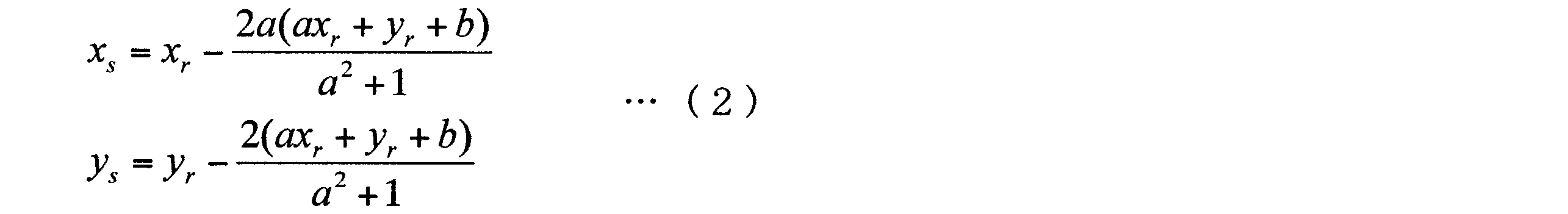
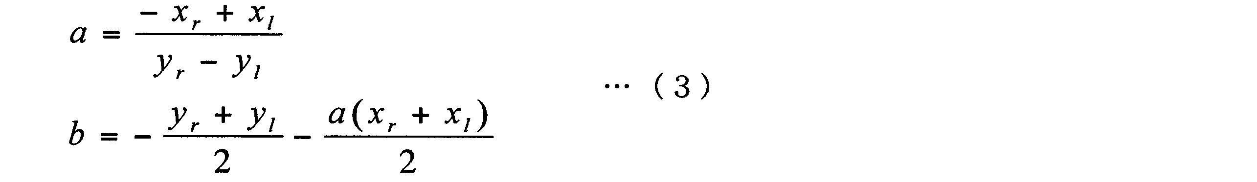
図9は、本発明の実施の形態2に係る視線方向判定装置の構成を示すブロック図である。本実施の形態の説明に当たり、図1と同一構成部分には同一番号を付して重複箇所の説明を省略する。
実施の形態3は、視線方向検出装置の検出誤差を自動的に補正する機能を有する、自動校正機能付き視線方向検出装置の適用例である。

図14は、本発明の実施の形態4に係る視線方向判定装置の構成を示すブロック図である。
110 画像入力部
111 撮像部
112 照射部
113 同期部
120 顔検出部
130 顔部品検出部
140 画像特徴検出部
141 瞳孔検出部
142 角膜反射像検出部
150 線対称位置算出部
160 評価値算出部
170 視線方向判定部
501 顔方向算出部
502 顔視線方向判定部
600 自動校正機能付き視線方向検出装置
610 視線方向算出部
620 視線検出校正部
630 校正パラメータ記憶部
640 出力部
1400 視線方向判定装置
1401 撮像部
1402 瞳孔検出部
1403 角膜反射像検出部
1404 線対称位置算出部
1405 視線方向判定部
1501 右目の瞳孔
1502 左目の瞳孔
1503 右目の眼球
1504 左目の眼球
1505 右目の瞳孔の中心と左目の瞳孔の中心とを結ぶ線分
1506 平面
1507 垂線
1508 垂線
1509 垂直二等分線
1510 垂線の足
1511 垂線の足
1600 顔画像
1601 右目
1602 左目
1603 右目の角膜
1604 左目の角膜
1605 右目の瞳孔
1606 左目の瞳孔
1607 右目の角膜反射像
1608 左目の角膜反射像
1609 線分
1610 垂直二等分線
1611 角膜投影像 1700 視線方向判定装置
1701 警報装置部
Claims (7)
- 両目を含む顔画像を撮像する撮像部と、
前記両目の角膜を光源によって照射する照射部と、
前記顔画像から、前記両目のうち、一方の目の瞳孔の中心座標である第1座標と、他方の目の瞳孔の中心座標である第2座標とを検出する瞳孔検出部と、
前記顔画像から、前記一方の目の角膜における前記光源の角膜反射像の中心座標である第3座標と、前記他方の目の角膜における前記光源の角膜反射像の中心座標である第4座標とを検出する角膜反射像検出部と、
前記第1座標と前記第2座標とを結ぶ第1の線分の垂直二等分線を算出し、前記垂直二等分線に対して前記第3座標と線対称の位置座標である線対称位置座標を算出する線対称位置算出部と、
前記第4座標と前記線対称位置座標との座標距離を算出し、前記座標距離と所定の閾値との比較に基づいて、前記両目の視線方向を判定する視線方向判定部と、
を備える視線方向判定装置。 - 前記撮像部から前記第1の線分を含む平面への垂線の足と、前記照射部から前記平面への垂線の足とを結ぶ第2の線分が、前記第1の線分と直行する請求項1記載の視差方向判定装置。
- 警報装置を更に有し、
前記警報装置は、前記視線方向判定部における判定結果を受け、前記視線方向が特定の方向ではないという判定結果を受けた回数をカウントし、前記カウント数が所定の回数を超えた場合は警告を発する請求項1記載の視線方向判定装置。 - 前記警報装置は、前記視線方向が前記特定の方向であるという判定結果を受けた場合、前記カウント数をゼロにする請求項3記載の視線方向判定装置。
- 前記顔画像に基づいて顔方向を判定する顔方向算出部と、
前記顔方向算出部において前記顔方向が前記特定の方向であると判定された場合は、前記座標距離と前記所定の閾値とに基づいて、視線方向を判定する顔視線方向判定部を更に有し、
前記視線方向判断部は、顔の方向をパラメータにして、視線方向を判定する請求項1記載の視線方向判定装置。 - 前記撮像部において取得した前記顔画像から視線方向情報を算出する視線方向算出部と、
前記視線方向判定部における判定結果と、前記視線方向算出情報とに基づいて、前記視線方向のずれ値を算出し、前記ずれ値に基づいて視線方向を校正する校正部と、
を備える請求項1記載の視線方向判定装置。 - 両目を含む顔画像を撮像し、
前記両目の角膜を光源によって照射し、
前記顔画像から、前記両目のうち、一方の目の瞳孔の中心座標である第1座標と、他方の目の瞳孔の中心座標である第2座標とを検出し、
前記顔画像から、前記一方の目の角膜における前記光源の角膜反射像の中心座標である第3座標と、前記他方の目の角膜における前記光源の角膜反射像の中心座標である第4座標とを検出し、
前記第1座標と前記第2座標とを結ぶ第1の線分の垂直二等分線を算出し、前記垂直二等分線に対して前記第3座標と線対称の位置座標である線対称位置座標を算出し、
前記第4座標と前記線対称位置座標との座標距離を算出し、前記座標距離と所定の閾値との比較に基づいて、前記両目の視線方向を判定する視線方向判定方法。
Priority Applications (5)
| Application Number | Priority Date | Filing Date | Title |
|---|---|---|---|
| JP2010530731A JP5230748B2 (ja) | 2008-09-26 | 2009-09-25 | 視線方向判定装置及び視線方向判定方法 |
| US13/121,220 US8538044B2 (en) | 2008-09-26 | 2009-09-25 | Line-of-sight direction determination device and line-of-sight direction determination method |
| EP09815894.2A EP2338416B1 (en) | 2008-09-26 | 2009-09-25 | Line-of-sight direction determination device and line-of-sight direction determination method |
| CN2009801354621A CN102149325B (zh) | 2008-09-26 | 2009-09-25 | 视线方向判定装置及视线方向判定方法 |
| US14/027,501 US20140043459A1 (en) | 2008-09-26 | 2013-09-16 | Line-of-sight direction determination device and line-of-sight direction determination method |
Applications Claiming Priority (2)
| Application Number | Priority Date | Filing Date | Title |
|---|---|---|---|
| JP2008-248877 | 2008-09-26 | ||
| JP2008248877 | 2008-09-26 |
Related Child Applications (2)
| Application Number | Title | Priority Date | Filing Date |
|---|---|---|---|
| US13/121,220 A-371-Of-International US8538044B2 (en) | 2008-09-26 | 2009-09-25 | Line-of-sight direction determination device and line-of-sight direction determination method |
| US14/027,501 Continuation US20140043459A1 (en) | 2008-09-26 | 2013-09-16 | Line-of-sight direction determination device and line-of-sight direction determination method |
Publications (1)
| Publication Number | Publication Date |
|---|---|
| WO2010035472A1 true WO2010035472A1 (ja) | 2010-04-01 |
Family
ID=42059485
Family Applications (1)
| Application Number | Title | Priority Date | Filing Date |
|---|---|---|---|
| PCT/JP2009/004853 Ceased WO2010035472A1 (ja) | 2008-09-26 | 2009-09-25 | 視線方向判定装置及び視線方向判定方法 |
Country Status (5)
| Country | Link |
|---|---|
| US (2) | US8538044B2 (ja) |
| EP (1) | EP2338416B1 (ja) |
| JP (1) | JP5230748B2 (ja) |
| CN (1) | CN102149325B (ja) |
| WO (1) | WO2010035472A1 (ja) |
Cited By (16)
| Publication number | Priority date | Publication date | Assignee | Title |
|---|---|---|---|---|
| CN102510734A (zh) * | 2010-07-20 | 2012-06-20 | 松下电器产业株式会社 | 瞳孔检测装置及瞳孔检测方法 |
| CN104114079A (zh) * | 2011-10-24 | 2014-10-22 | Iriss医疗科技有限公司 | 用于识别眼部健康状况的系统和方法 |
| JP2015159550A (ja) * | 2015-03-19 | 2015-09-03 | オリンパス株式会社 | 撮像装置、撮像方法およびプログラム |
| JP2017063995A (ja) * | 2015-09-29 | 2017-04-06 | 株式会社トプコン | 眼科装置 |
| EP2649932A4 (en) * | 2010-12-08 | 2017-06-14 | National University Corporation Shizuoka University | Method for detecting point of gaze and device for detecting point of gaze |
| WO2017195450A1 (ja) * | 2016-05-10 | 2017-11-16 | ソニー株式会社 | 情報処理装置、情報処理方法 |
| JP2018025987A (ja) * | 2016-08-10 | 2018-02-15 | 富士通株式会社 | 視線検出装置、視線検出方法、及び視線検出プログラム |
| CN109464236A (zh) * | 2017-09-08 | 2019-03-15 | 拉碧斯半导体株式会社 | 护目镜式显示装置、视线检测方法以及视线检测系统 |
| KR20190135598A (ko) * | 2018-05-29 | 2019-12-09 | 상명대학교산학협력단 | 얼굴 대칭성 측정 장치 및 방법 |
| WO2020065790A1 (ja) * | 2018-09-26 | 2020-04-02 | 日本電気株式会社 | 推定装置、推定方法、および記憶媒体 |
| WO2021140579A1 (ja) * | 2020-01-08 | 2021-07-15 | 三菱電機株式会社 | 瞳孔検出装置、視線検出装置、搭乗者監視システム及び瞳孔検出方法 |
| WO2021171396A1 (ja) * | 2020-02-26 | 2021-09-02 | 三菱電機株式会社 | 瞳孔位置検出装置、視線検出装置、及び瞳孔位置検出方法 |
| WO2021171395A1 (ja) * | 2020-02-26 | 2021-09-02 | 三菱電機株式会社 | 瞳孔位置検出装置、視線検出装置、及び瞳孔位置検出方法 |
| JP2022023643A (ja) * | 2020-07-27 | 2022-02-08 | キヤノン株式会社 | 視線位置処理装置、撮像装置、学習装置、視線位置処理方法、学習方法、及びプログラム |
| US20220415083A1 (en) * | 2021-06-29 | 2022-12-29 | Samsung Electronics Co., Ltd. | Electronic device and operating method of electronic device for correcting error during gaze direction recognition |
| KR102892267B1 (ko) | 2023-02-14 | 2025-11-28 | 한국기술교육대학교 산학협력단 | 안면거울과 얼굴각도 추정에 의한 안검하수 비전장치 및 그 제어방법 |
Families Citing this family (53)
| Publication number | Priority date | Publication date | Assignee | Title |
|---|---|---|---|---|
| JP5634111B2 (ja) * | 2010-04-28 | 2014-12-03 | キヤノン株式会社 | 映像編集装置、映像編集方法及びプログラム |
| WO2011148455A1 (ja) * | 2010-05-25 | 2011-12-01 | 富士通株式会社 | 映像処理装置、映像処理方法及び映像処理プログラム |
| JP5618686B2 (ja) * | 2010-08-03 | 2014-11-05 | キヤノン株式会社 | 視線検出装置、視線検出方法及びプログラム |
| JP5714951B2 (ja) * | 2011-03-22 | 2015-05-07 | パナソニック株式会社 | 両眼瞳孔検査装置 |
| CN104094197B (zh) * | 2012-02-06 | 2018-05-11 | 索尼爱立信移动通讯股份有限公司 | 利用投影仪的注视追踪 |
| US9148537B1 (en) * | 2012-05-18 | 2015-09-29 | hopTo Inc. | Facial cues as commands |
| US9395826B1 (en) | 2012-05-25 | 2016-07-19 | hopTo Inc. | System for and method of translating motion-based user input between a client device and an application host computer |
| CN103054548A (zh) * | 2012-07-05 | 2013-04-24 | 东北电力大学 | 凝视点测量装置及瞳孔、普尔钦亮斑识别方法 |
| JP2014048936A (ja) * | 2012-08-31 | 2014-03-17 | Omron Corp | ジェスチャ認識装置、その制御方法、表示機器、および制御プログラム |
| US8937552B1 (en) * | 2013-01-02 | 2015-01-20 | The Boeing Company | Heads down warning system |
| US9730655B2 (en) * | 2013-01-21 | 2017-08-15 | Tracy J. Stark | Method for improved detection of nodules in medical images |
| JP6157165B2 (ja) * | 2013-03-22 | 2017-07-05 | キヤノン株式会社 | 視線検出装置及び撮像装置 |
| KR102037417B1 (ko) | 2013-08-13 | 2019-10-28 | 삼성전자주식회사 | 홍채 영상 촬영 방법, 상기 방법을 기록한 컴퓨터 판독 가능 저장매체 및 홍채 영상 촬영 장치 |
| WO2015064080A1 (ja) * | 2013-11-01 | 2015-05-07 | パナソニックIpマネジメント株式会社 | 視線方向検出装置および視線方向検出方法 |
| CN103594003B (zh) * | 2013-11-13 | 2015-11-25 | 安徽三联交通应用技术股份有限公司 | 一种用于驾驶人的远程监控与异常预警的方法 |
| KR101470243B1 (ko) * | 2013-11-15 | 2014-12-05 | 현대자동차주식회사 | 시선 검출 장치 및 그 시선 검출 방법 |
| US9189692B2 (en) * | 2014-02-14 | 2015-11-17 | GM Global Technology Operations LLC | Methods and systems for detecting driver attention to objects |
| TWI577327B (zh) * | 2014-08-14 | 2017-04-11 | 由田新技股份有限公司 | 瞳孔定位方法與裝置及其電腦程式產品 |
| KR101610496B1 (ko) * | 2014-08-26 | 2016-04-07 | 현대자동차주식회사 | 시선 추적 방법 및 장치 |
| KR20160025316A (ko) * | 2014-08-27 | 2016-03-08 | 현대자동차주식회사 | 동공 검출 시스템 및 그 방법 |
| JP6346525B2 (ja) * | 2014-08-29 | 2018-06-20 | アルプス電気株式会社 | 視線検出装置 |
| JP2016106668A (ja) * | 2014-12-02 | 2016-06-20 | ソニー株式会社 | 情報処理装置、情報処理方法、およびプログラム |
| EP3236338B1 (en) | 2014-12-17 | 2019-12-18 | Sony Corporation | Information processing apparatus, information processing method and program |
| CN105704369B (zh) * | 2016-01-20 | 2019-02-15 | 努比亚技术有限公司 | 一种信息处理方法及装置、电子设备 |
| CN105913487B (zh) | 2016-04-09 | 2018-07-06 | 北京航空航天大学 | 一种基于人眼图像中虹膜轮廓分析匹配的视线方向计算方法 |
| CN106123819B (zh) * | 2016-06-29 | 2018-07-24 | 华中科技大学 | 一种注意力焦点测量方法 |
| US9875398B1 (en) * | 2016-06-30 | 2018-01-23 | The United States Of America As Represented By The Secretary Of The Army | System and method for face recognition with two-dimensional sensing modality |
| US12094224B2 (en) * | 2016-07-01 | 2024-09-17 | Eyesight Mobile Technologies Ltd. | System and method for driver monitoring |
| JP6800091B2 (ja) * | 2017-06-09 | 2020-12-16 | 株式会社豊田中央研究所 | 視線計測装置及びプログラム |
| CN107323338B (zh) * | 2017-07-03 | 2020-04-03 | 北京汽车研究总院有限公司 | 车用转向灯控制系统、控制方法及车辆 |
| JP7180067B2 (ja) * | 2017-11-06 | 2022-11-30 | 日本電気株式会社 | 運転支援装置 |
| DK3480729T3 (da) * | 2017-11-07 | 2023-04-03 | Tata Consultancy Services Ltd | System og fremgangsmåde til ansigtspositionssporing og alarmering af en bruger |
| KR102460665B1 (ko) * | 2017-12-14 | 2022-10-31 | 삼성전자주식회사 | 응시 거리를 결정하는 방법 및 디바이스 |
| JP6717330B2 (ja) | 2018-03-15 | 2020-07-01 | オムロン株式会社 | 視線検出装置、該視線検出装置の制御方法、角膜反射像位置の検出方法、及びコンピュータプログラム |
| JP7388349B2 (ja) * | 2018-03-29 | 2023-11-29 | ソニーグループ株式会社 | 情報処理装置、情報処理方法、及びプログラム |
| CN108891414A (zh) * | 2018-05-22 | 2018-11-27 | 通化市聚诚网络科技有限公司 | 一种车道变换辅助方法及装置 |
| JP7180228B2 (ja) * | 2018-09-20 | 2022-11-30 | いすゞ自動車株式会社 | 車両用監視装置 |
| JP7192872B2 (ja) | 2018-10-16 | 2022-12-20 | 日本電気株式会社 | 虹彩認証装置、虹彩認証方法、虹彩認証プログラムおよび記録媒体 |
| JP7173836B2 (ja) * | 2018-11-05 | 2022-11-16 | 京セラ株式会社 | コントローラ、位置判定装置、位置判定システム、表示システム、プログラム、および記録媒体 |
| JP7192570B2 (ja) * | 2019-02-27 | 2022-12-20 | 株式会社Jvcケンウッド | 記録再生装置、記録再生方法およびプログラム |
| CN113557519A (zh) * | 2019-03-14 | 2021-10-26 | 日本电气株式会社 | 信息处理设备、信息处理系统、信息处理方法以及记录介质 |
| TWI725441B (zh) * | 2019-05-15 | 2021-04-21 | 劉恩銓 | 生物訊號檢測分析方法 |
| CN110363133B (zh) * | 2019-07-10 | 2021-06-01 | 广州市百果园信息技术有限公司 | 一种视线检测和视频处理的方法、装置、设备和存储介质 |
| CN111860440B (zh) * | 2020-07-31 | 2024-08-06 | 广州繁星互娱信息科技有限公司 | 人脸特征点的位置调整方法、装置、终端及存储介质 |
| KR102497805B1 (ko) * | 2020-07-31 | 2023-02-10 | 주식회사 펫타버스 | 인공지능 기반 반려동물 신원확인 시스템 및 방법 |
| CN112270283A (zh) * | 2020-11-04 | 2021-01-26 | 北京百度网讯科技有限公司 | 异常驾驶行为确定方法、装置、设备、车辆和介质 |
| CN112541400B (zh) * | 2020-11-20 | 2024-06-21 | 小米科技(武汉)有限公司 | 基于视线估计的行为识别方法及装置、电子设备、存储介质 |
| US11762078B2 (en) * | 2021-01-27 | 2023-09-19 | Qualcomm Incorporated | Line of sight determination based on direction and distance thresholds |
| JP7640291B2 (ja) | 2021-03-08 | 2025-03-05 | 本田技研工業株式会社 | 較正装置及び較正方法 |
| CN113116292B (zh) * | 2021-04-22 | 2023-07-11 | 上海交通大学医学院附属第九人民医院 | 基于眼部外观图像的眼位测量方法、装置、终端和设备 |
| JP2024013947A (ja) * | 2022-07-21 | 2024-02-01 | キヤノン株式会社 | 撮像装置、撮像装置の撮像方法およびプログラム |
| JP7697913B2 (ja) * | 2022-07-25 | 2025-06-24 | トヨタ自動車株式会社 | 視線推定装置、視線推定用コンピュータプログラム及び視線推定方法 |
| CN118680511B (zh) * | 2024-08-26 | 2025-03-07 | 宁波法里奥光学科技发展有限公司 | 一种人眼三维定位装置和方法 |
Citations (4)
| Publication number | Priority date | Publication date | Assignee | Title |
|---|---|---|---|---|
| JPH024313A (ja) * | 1988-06-13 | 1990-01-09 | Nippon Telegr & Teleph Corp <Ntt> | 注視位置検出装置 |
| JP2002119478A (ja) * | 2000-10-19 | 2002-04-23 | Canon Inc | 視線検出機能付き装置 |
| WO2008007781A1 (en) * | 2006-07-14 | 2008-01-17 | Panasonic Corporation | Visual axis direction detection device and visual line direction detection method |
| JP2008126329A (ja) * | 2006-11-17 | 2008-06-05 | Toyota Motor Corp | 音声認識ロボットおよび音声認識ロボットの制御方法 |
Family Cites Families (6)
| Publication number | Priority date | Publication date | Assignee | Title |
|---|---|---|---|---|
| JP3186072B2 (ja) | 1991-01-08 | 2001-07-11 | キヤノン株式会社 | 視線検出装置を有する機器 |
| JPH08297019A (ja) * | 1995-04-27 | 1996-11-12 | Nissan Motor Co Ltd | 車両用視線方向計測装置 |
| US5926655A (en) * | 1995-08-15 | 1999-07-20 | Canon Kabushiki Kaisha | Line of sight detection device and an apparatus having a line of sight detection device |
| JP2005066023A (ja) | 2003-08-25 | 2005-03-17 | Nissan Motor Co Ltd | 運転者状態検出装置 |
| JP4376685B2 (ja) * | 2004-04-16 | 2009-12-02 | 本田技研工業株式会社 | 視線検出装置 |
| US7580545B2 (en) * | 2005-10-03 | 2009-08-25 | Avago Technologies General Ip (Singapore) Pte. Ltd. | Method and system for determining gaze direction in a pupil detection system |
-
2009
- 2009-09-25 EP EP09815894.2A patent/EP2338416B1/en active Active
- 2009-09-25 WO PCT/JP2009/004853 patent/WO2010035472A1/ja not_active Ceased
- 2009-09-25 US US13/121,220 patent/US8538044B2/en active Active
- 2009-09-25 CN CN2009801354621A patent/CN102149325B/zh active Active
- 2009-09-25 JP JP2010530731A patent/JP5230748B2/ja active Active
-
2013
- 2013-09-16 US US14/027,501 patent/US20140043459A1/en not_active Abandoned
Patent Citations (4)
| Publication number | Priority date | Publication date | Assignee | Title |
|---|---|---|---|---|
| JPH024313A (ja) * | 1988-06-13 | 1990-01-09 | Nippon Telegr & Teleph Corp <Ntt> | 注視位置検出装置 |
| JP2002119478A (ja) * | 2000-10-19 | 2002-04-23 | Canon Inc | 視線検出機能付き装置 |
| WO2008007781A1 (en) * | 2006-07-14 | 2008-01-17 | Panasonic Corporation | Visual axis direction detection device and visual line direction detection method |
| JP2008126329A (ja) * | 2006-11-17 | 2008-06-05 | Toyota Motor Corp | 音声認識ロボットおよび音声認識ロボットの制御方法 |
Cited By (29)
| Publication number | Priority date | Publication date | Assignee | Title |
|---|---|---|---|---|
| CN102510734A (zh) * | 2010-07-20 | 2012-06-20 | 松下电器产业株式会社 | 瞳孔检测装置及瞳孔检测方法 |
| CN102510734B (zh) * | 2010-07-20 | 2015-05-13 | 松下电器(美国)知识产权公司 | 瞳孔检测装置及瞳孔检测方法 |
| EP2596746A4 (en) * | 2010-07-20 | 2017-08-30 | Panasonic Intellectual Property Corporation of America | Pupil detection device and pupil detection method |
| EP2649932A4 (en) * | 2010-12-08 | 2017-06-14 | National University Corporation Shizuoka University | Method for detecting point of gaze and device for detecting point of gaze |
| CN104114079A (zh) * | 2011-10-24 | 2014-10-22 | Iriss医疗科技有限公司 | 用于识别眼部健康状况的系统和方法 |
| JP2014530730A (ja) * | 2011-10-24 | 2014-11-20 | アイリス・メディカル・テクノロジーズ・リミテッド | 目の症状を特定するためのシステムおよび方法 |
| JP2015159550A (ja) * | 2015-03-19 | 2015-09-03 | オリンパス株式会社 | 撮像装置、撮像方法およびプログラム |
| JP2017063995A (ja) * | 2015-09-29 | 2017-04-06 | 株式会社トプコン | 眼科装置 |
| US10757337B2 (en) | 2016-05-10 | 2020-08-25 | Sony Corporation | Information processing apparatus and information processing method to control exposure for imaging the eye |
| WO2017195450A1 (ja) * | 2016-05-10 | 2017-11-16 | ソニー株式会社 | 情報処理装置、情報処理方法 |
| JP2018025987A (ja) * | 2016-08-10 | 2018-02-15 | 富士通株式会社 | 視線検出装置、視線検出方法、及び視線検出プログラム |
| CN109464236A (zh) * | 2017-09-08 | 2019-03-15 | 拉碧斯半导体株式会社 | 护目镜式显示装置、视线检测方法以及视线检测系统 |
| KR20190135598A (ko) * | 2018-05-29 | 2019-12-09 | 상명대학교산학협력단 | 얼굴 대칭성 측정 장치 및 방법 |
| KR102115150B1 (ko) | 2018-05-29 | 2020-06-08 | 상명대학교산학협력단 | 얼굴 대칭성 측정 장치 및 방법 |
| US12125315B2 (en) | 2018-09-26 | 2024-10-22 | Nec Corporation | Direction estimation device, direction estimation method, and storage medium |
| US12112570B2 (en) | 2018-09-26 | 2024-10-08 | Nec Corporation | Direction estimation device, direction estimation method, and storage medium |
| US12217539B2 (en) | 2018-09-26 | 2025-02-04 | Nec Corporation | Estimation device, estimation method, and storage medium |
| WO2020065790A1 (ja) * | 2018-09-26 | 2020-04-02 | 日本電気株式会社 | 推定装置、推定方法、および記憶媒体 |
| JP7278425B2 (ja) | 2020-01-08 | 2023-05-19 | 三菱電機株式会社 | 瞳孔検出装置、視線検出装置、搭乗者監視システム及び瞳孔検出方法 |
| WO2021140579A1 (ja) * | 2020-01-08 | 2021-07-15 | 三菱電機株式会社 | 瞳孔検出装置、視線検出装置、搭乗者監視システム及び瞳孔検出方法 |
| JPWO2021140579A1 (ja) * | 2020-01-08 | 2021-07-15 | ||
| US12277728B2 (en) | 2020-01-08 | 2025-04-15 | Mitsubishi Electric Corporation | Pupil detection device, line-of-sight detection device, occupant monitoring system, and pupil detection method |
| WO2021171395A1 (ja) * | 2020-02-26 | 2021-09-02 | 三菱電機株式会社 | 瞳孔位置検出装置、視線検出装置、及び瞳孔位置検出方法 |
| WO2021171396A1 (ja) * | 2020-02-26 | 2021-09-02 | 三菱電機株式会社 | 瞳孔位置検出装置、視線検出装置、及び瞳孔位置検出方法 |
| JP2022023643A (ja) * | 2020-07-27 | 2022-02-08 | キヤノン株式会社 | 視線位置処理装置、撮像装置、学習装置、視線位置処理方法、学習方法、及びプログラム |
| JP7538647B2 (ja) | 2020-07-27 | 2024-08-22 | キヤノン株式会社 | 視線位置処理装置、撮像装置、学習装置、視線位置処理方法、学習方法、及びプログラム |
| US20220415083A1 (en) * | 2021-06-29 | 2022-12-29 | Samsung Electronics Co., Ltd. | Electronic device and operating method of electronic device for correcting error during gaze direction recognition |
| US12223769B2 (en) * | 2021-06-29 | 2025-02-11 | Samsung Electronics Co., Ltd. | Electronic device and operating method of electronic device for correcting error during gaze direction recognition |
| KR102892267B1 (ko) | 2023-02-14 | 2025-11-28 | 한국기술교육대학교 산학협력단 | 안면거울과 얼굴각도 추정에 의한 안검하수 비전장치 및 그 제어방법 |
Also Published As
| Publication number | Publication date |
|---|---|
| JP5230748B2 (ja) | 2013-07-10 |
| EP2338416A4 (en) | 2018-02-14 |
| CN102149325B (zh) | 2013-01-02 |
| US20140043459A1 (en) | 2014-02-13 |
| US8538044B2 (en) | 2013-09-17 |
| EP2338416B1 (en) | 2019-02-27 |
| US20110249868A1 (en) | 2011-10-13 |
| CN102149325A (zh) | 2011-08-10 |
| EP2338416A1 (en) | 2011-06-29 |
| JPWO2010035472A1 (ja) | 2012-02-16 |
Similar Documents
| Publication | Publication Date | Title |
|---|---|---|
| JP5230748B2 (ja) | 視線方向判定装置及び視線方向判定方法 | |
| JP5137833B2 (ja) | 視線方向検出装置および視線方向検出方法 | |
| US10521683B2 (en) | Glare reduction | |
| CN108621940B (zh) | 车辆的显示系统及车辆的显示系统的控制方法 | |
| EP2649932A1 (en) | Method for detecting point of gaze and device for detecting point of gaze | |
| JP6840697B2 (ja) | 視線方向推定装置、視線方向推定方法、及び視線方向推定プログラム | |
| JP2016173313A (ja) | 視線方向推定システム、視線方向推定方法及び視線方向推定プログラム | |
| JPWO2018030515A1 (ja) | 視線検出装置 | |
| WO2015064080A1 (ja) | 視線方向検出装置および視線方向検出方法 | |
| JP6601351B2 (ja) | 視線計測装置 | |
| US10997861B2 (en) | Luminance control device, luminance control system, and luminance control method | |
| JP2019215688A (ja) | 自動キャリブレーションを行う視線計測装置、視線計測方法および視線計測プログラム | |
| JP2019098024A (ja) | 画像処理装置及び画像処理方法 | |
| JP2012022646A (ja) | 視線方向検出装置、視線方向検出方法及び安全運転評価システム | |
| JP2005261728A (ja) | 視線方向認識装置及び視線方向認識プログラム | |
| CN109791294B (zh) | 用于运行具有数据眼镜的显示系统的方法和设备 | |
| JP6906943B2 (ja) | 車載器 | |
| JP2018101212A (ja) | 車載器および顔正面度算出方法 | |
| CN114004889A (zh) | 一种融合头部姿态的三维眼球移动方向判断方法 | |
| JP2017138645A (ja) | 視線検出装置 | |
| US10572730B2 (en) | Visual line measuring device and visual line measuring method | |
| JP2005081101A (ja) | 視線方向検出装置及び視線方向検出方法 | |
| WO2015080003A1 (ja) | 瞳孔検出装置、視線検出装置および瞳孔検出方法 | |
| JP2020081756A (ja) | 顔画像処理装置、画像観察システム、及び瞳孔検出システム | |
| JP2024120464A (ja) | 瞳孔検出装置及び瞳孔検出方法 |
Legal Events
| Date | Code | Title | Description |
|---|---|---|---|
| WWE | Wipo information: entry into national phase |
Ref document number: 200980135462.1 Country of ref document: CN |
|
| 121 | Ep: the epo has been informed by wipo that ep was designated in this application |
Ref document number: 09815894 Country of ref document: EP Kind code of ref document: A1 |
|
| WWE | Wipo information: entry into national phase |
Ref document number: 2010530731 Country of ref document: JP |
|
| NENP | Non-entry into the national phase |
Ref country code: DE |
|
| WWE | Wipo information: entry into national phase |
Ref document number: 2009815894 Country of ref document: EP |
|
| WWE | Wipo information: entry into national phase |
Ref document number: 13121220 Country of ref document: US |