WO2010041338A1 - 調節装置 - Google Patents
調節装置 Download PDFInfo
- Publication number
- WO2010041338A1 WO2010041338A1 PCT/JP2008/068499 JP2008068499W WO2010041338A1 WO 2010041338 A1 WO2010041338 A1 WO 2010041338A1 JP 2008068499 W JP2008068499 W JP 2008068499W WO 2010041338 A1 WO2010041338 A1 WO 2010041338A1
- Authority
- WO
- WIPO (PCT)
- Prior art keywords
- signal
- adjustment
- unit
- value
- previous
- Prior art date
- Legal status (The legal status is an assumption and is not a legal conclusion. Google has not performed a legal analysis and makes no representation as to the accuracy of the status listed.)
- Ceased
Links
Images


Classifications
-
- G—PHYSICS
- G05—CONTROLLING; REGULATING
- G05B—CONTROL OR REGULATING SYSTEMS IN GENERAL; FUNCTIONAL ELEMENTS OF SUCH SYSTEMS; MONITORING OR TESTING ARRANGEMENTS FOR SUCH SYSTEMS OR ELEMENTS
- G05B11/00—Automatic controllers
- G05B11/01—Automatic controllers electric
- G05B11/36—Automatic controllers electric with provision for obtaining particular characteristics, e.g. proportional, integral, differential
-
- G—PHYSICS
- G05—CONTROLLING; REGULATING
- G05B—CONTROL OR REGULATING SYSTEMS IN GENERAL; FUNCTIONAL ELEMENTS OF SUCH SYSTEMS; MONITORING OR TESTING ARRANGEMENTS FOR SUCH SYSTEMS OR ELEMENTS
- G05B11/00—Automatic controllers
- G05B11/01—Automatic controllers electric
- G05B11/36—Automatic controllers electric with provision for obtaining particular characteristics, e.g. proportional, integral, differential
- G05B11/42—Automatic controllers electric with provision for obtaining particular characteristics, e.g. proportional, integral, differential for obtaining a characteristic which is both proportional and time-dependent, e.g. P. I., P. I. D.
Definitions
- the present invention relates to an adjustment device that is mounted on a railway vehicle and controls deceleration.
- a PI or PID (P: proportional, I: integral, D: derivative) adjusting device (hereinafter referred to as “adjusting device”) adjusts an operation signal so that a process value (also referred to as a measured value) to be controlled matches a target value.
- adjusting device adjusts an operation signal so that a process value (also referred to as a measured value) to be controlled matches a target value.
- a process value also referred to as a measured value
- a configuration is adopted in which an output limiting unit that limits the upper and lower limits and the rate of change is provided in the operation signal.
- the limit deviation signal (operation signal-operation signal with limitation) may endlessly expand. Thereafter, when recovering from saturation, a so-called reset windup phenomenon occurs in which the limited operation signal continues to be saturated until the operation signal is returned to the limit range, and overshoot occurs.
- a general adjusting device performs a process for preventing the reset windup (hereinafter referred to as “anti-reset windup process”).
- the adjustment device disclosed in the above-mentioned Patent Document 1 is a state in which the limited deviation signal is relatively low in a state where the limited operation signal to the controlled object is saturated, and the adjustment signal target value and process value When the deviation of V is approaching “0”, there is a problem that saturation and release of saturation are repeated for each control period, and a hunting phenomenon occurs in which the limited operation signal fluctuates finely. Furthermore, due to the hunting phenomenon, there is a problem that overwinding is superimposed as many times as the number of toggle operations, and reset windup may occur.
- the present invention has been made in view of the above, and obtains an adjusting device that can stabilize a restricted operation signal to a controlled object even in a state where the restricted operation signal to the controlled object is just saturated. For the purpose.
- an adjustment device includes an adjustment calculation unit that calculates and outputs an operation signal so that a process value from a control target matches a target value, and the adjustment calculation
- An adjustment device including an output restriction unit that restricts the operation signal from the output unit and outputs the operation signal to the control target, wherein the adjustment calculation unit includes at least a speed-type integral adjustment unit or a position-type integral adjustment unit, and the output restriction The unit has a function of outputting a limit deviation signal indicating a degree of deviation from a predetermined limit, and is generated in the previous control cycle based on the speed-type integral adjustment signal output from the adjustment calculation unit and the limit deviation signal.
- An overintegration calculation unit that calculates a previous overintegration signal corresponding to the previous overintegration, and the adjustment calculation unit corrects the integral value stored by the previous overintegration signal by the previous overintegration signal. , Providing the function of removing the previous over-integration, characterized by.
- the adjusting device of the present invention when saturation occurs, a limited operation signal to the control target is removed in the next control cycle in order to remove the overintegration (previous overintegration) that occurred in the previous control cycle. Even in a state in which is just saturated, there is an effect that the limited operation signal to the control target can be stabilized.
- FIG. 1 is a diagram illustrating an example of the configuration of the adjusting device according to the first embodiment.
- FIG. 2 is a diagram illustrating an example of the configuration of the overintegration calculation unit according to the first embodiment.
- FIG. 3 is a diagram illustrating an example of the configuration of the adjustment calculation unit according to the first embodiment.
- FIG. 4 is a diagram illustrating an example of a configuration of an adjustment calculation unit according to the second embodiment.
- FIG. 5 is a diagram illustrating an example of a configuration of the position shape I adjusting unit according to the second embodiment.
- FIG. 6 is a diagram illustrating an example of the configuration of the position shape I adjusting unit according to the third embodiment.
- FIG. 7 is a diagram illustrating an example of the configuration of the output limiting unit according to the first embodiment.
- FIG. 8 is a diagram illustrating an example of the configuration of the output limiting unit according to the fourth embodiment.
- FIG. 9 is a diagram illustrating an example of the configuration of the adjusting device according to the fifth embodiment.
- FIG. 10 is a diagram illustrating an example of the configuration of the output limiting unit according to the sixth embodiment.
- FIG. 11 is a diagram of an example of the configuration of the output restriction unit according to the seventh embodiment.
- FIG. 12 is a diagram illustrating an example of an operating state of a conventional adjustment device.
- FIG. 13 is a diagram illustrating an example of an operation state of the adjustment device according to the first embodiment.
- FIG. 14 is a diagram illustrating an example of an operation state of the quantization unit.
- FIG. 1 is a diagram illustrating an example of the configuration of the adjusting device according to the first embodiment.
- the role of the adjusting device 1 is to provide a limited operation signal MV2 [output to the controlled object 2 [MV2] so that the target value SV (also referred to as a set value) matches the process value PV (also referred to as a measured value) of the controlled object 2.
- MV2 limited operation signal
- SV also referred to as a set value
- PV also referred to as a measured value
- the adjustment device 1 calculates an input unit 11 that performs input processing of the target value SV, an input unit 12 that performs input processing of the process value PV of the control target 2, and a deviation e [n] of their outputs.
- the adjustment calculator 14 that calculates and outputs the operation signal MV [n] based on the deviation e [n], and the operation signal MV [n] is limited by a predetermined limit value.
- the limited operation signal MV2 [n] is output to the controlled object 2, and the output limiter 15 that outputs the limit deviation signal ⁇ [n] indicating the deviation from the predetermined limit, and the adjustment calculation unit 14 output.
- the previous overintegration signal ARW [n] corresponding to the overintegration generated in the previous control cycle (hereinafter referred to as “previous overintegration”) is obtained.
- the overintegration calculation unit 16 for calculating It is.
- the previous overintegration signal ARW [n] is input to the adjustment calculation unit 14 and corrects the integral value stored by itself to eliminate the previous overintegration.
- the adjusting device 1 is described as a single device in FIG. 1, it may be a part of software of a certain device, or may be a system configured by connecting a plurality of devices. .
- the name does not have to be an adjustment device, and is sometimes called “** control device” or “** control system”.
- [n] and [n-1] are basically added after the signal name.
- This n increases by 1 every control cycle after the system is started. That is, when X [n] is described, it indicates the value of X in the nth control cycle after the system is started. Simply, X [n] may be understood as the value of the current control cycle, and X [n ⁇ 1] as the value of the previous control cycle.
- Means for converting X [n] to X [n ⁇ 1] is indicated in this specification by the expression “storage unit”.
- the storage unit is “1 / Z” in terms of a pulse transfer function.
- a target value SV is input from a host system (not shown) via serial communication, an analog signal, or the like.
- a process value via serial communication, an analog signal, or the like is input from a sensor (not shown) that detects the process value PV of the control target 2.
- a sensor not shown
- digital filter processing or analog filter processing by an operational amplifier circuit may be added as necessary.
- oversampling is preferably performed at a sampling period several times the control period as necessary. In particular, when there are many noise components in the signal from the sensor, it is important for stabilization of control to remove the noise components in advance by a low-pass filter.
- the controlled object 2 may be hardware itself that is actually controlled, or may include a control device that controls the hardware. When operating the hardware directly, at least a DA converter and an actuator not shown are necessary. When operating a control device that controls the hardware, a real communication means and an analog signal interface not shown are used. Necessary. Further, when the control device itself for controlling the hardware is software in the same device as the adjustment device, no special interface means is required.
- FIG. 3 is a diagram illustrating an example of the configuration of the adjustment calculation unit according to the first embodiment.
- the role of the adjustment calculation unit 14 is to calculate and output the operation signal MV [n] based on the deviation e [n] so that the deviation is eliminated.
- the adjustment calculation unit 14 outputs a velocity type I adjustment signal ⁇ I [n], which is a velocity type integral adjustment signal, by a velocity type I operation (hereinafter referred to as “I operation”) based on the deviation e [n].
- speed form P + D adjustment signal ⁇ P A speed-type PD adjusting unit 22 that outputs [n] + ⁇ D [n] (first speed-type adjustment signal), and a speed-type P + D adjustment signal ⁇ P [n] + ⁇ D [n] to the speed-type I adjustment signal ⁇ I [n].
- ⁇ control period
- TI integration time
- Kp proportional gain
- the symbol TD in the calculation formula is a differential time.
- the speed type PD adjusting unit 22 is shown as an example, but a speed type P adjusting unit without D operation may be used.
- the mathematical expression of ⁇ D [n] is a complete differential expression, but a generally used incomplete differential expression may be used. Further, not limited to the speed type PID adjustment calculation, any type other than the speed type integral calculation may be used.
- ⁇ MV [n] ⁇ I [n] + ⁇ P [n] + ⁇ D [n] ⁇ ARW [n]
- the point to be emphasized is that, in this process, the integral value is corrected in order to eliminate the previous overintegration, and the speed form I adjustment signal ⁇ I [n] as shown in the conventional method is set to “0”. It is not that the integration is stopped or limited. Therefore, the effective value of the speed form I adjustment signal is ⁇ I [n], not ⁇ I [n] ⁇ ARW [n]. Therefore, ⁇ I [n] is used in the overintegration calculation unit 16 described later.
- FIG. 7 is a diagram of an example of the output restriction unit according to the first embodiment.
- the role of the output limiting unit 15 is to limit the operation signal MV [n] with a predetermined limit value, output the limited operation signal MV2 [n] to the control target 2, and to determine the degree of deviation from the predetermined limit. Is output from the limit deviation signal ⁇ [n].
- the output limiting unit 15 limits the magnitude of the operation signal MV [n] to a predetermined range, and limits the output change rate to a predetermined range, thereby limiting the operation signal MV2 with limitation. [N] is obtained and the change rate limiting unit 62 that outputs to the control target 2 and the limit deviation indicating a deviation from the predetermined limit by subtracting the limited operation signal MV2 [n] from the operation signal MV [n]. And a subtractor 63 that obtains and outputs the signal ⁇ [n].
- the input signal is assumed to be X [n] and the output signal is assumed to be Y [n].
- the upper / lower limit unit 61 sets a predetermined upper limit value when X [n] exceeds a predetermined upper limit value, and sets a predetermined lower limit value when the X [n] is lower than a predetermined lower limit value. Outputs the value of X [n] as Y [n].
- the input signal is assumed to be X [n] and the output signal is assumed to be Y [n].
- the output signal is assumed to be Y [n].
- X [n] exceeds Y [n-1] + predetermined upper limit value
- X [n] becomes Y [n -1] + If the value falls below the predetermined lower limit value, Y [n-1] + the predetermined lower limit value is output. Otherwise, X [n] is output as Y [n].
- the upper / lower limit limiting unit 61 and the change rate limiting unit 62 are configured in this order, but only one of them may be configured, or the reverse order may be configured.
- the upper and lower limit limiting unit 61 and the change rate limiting unit 62 are referred to as one or more limiting elements 60.
- FIG. 2 is a diagram illustrating an example of the configuration of the overintegration calculation unit according to the first embodiment.
- the role of the overintegration calculation unit 16 is based on the speed form I adjustment signal ⁇ I [n] and the limit deviation signal ⁇ [n], which corresponds to the previous overintegration signal ARW [n]. Is to calculate.
- the overintegration calculation unit 16 includes storage units 91 and 92 that respectively hold the previous values of the speed form I adjustment signal ⁇ I [n] and the limit deviation signal ⁇ [n], and the previous speed form I adjustment signal ⁇ I that is the output thereof. If the signs of [n ⁇ 1] and the previous limit deviation signal ⁇ [n ⁇ 1] are different signs, “0” is used. If the signs are the same sign, the absolute value of these two signals is given. And an absolute value minimum value selection unit 93 that selects a small value.
- the configuration of the absolute value minimum value selection unit 93 shown in FIG. 2 is an example that embodies the above-described processing. More specifically, when the values of the previous limit deviation signal ⁇ [n ⁇ 1] and the previous speed form I adjustment signal ⁇ I [n ⁇ 1] are both positive values, they are minimized through the upper contact of the switch unit. The value is input to the value selection unit (MIN), and the smaller value (that is, the value having the smaller absolute value) is selected. On the other hand, when the values of both signals are negative values, they are input to the maximum value selection unit (MAX) through the lower contact of the switch unit, and the larger value (that is, the smaller absolute value). Value) is selected.
- MIN value selection unit
- MAX maximum value selection unit
- the switch unit having the upper value of ⁇ [n ⁇ 1] passes through the upper contact to select the minimum value selection unit ( MIN), and the lower switch section is tilted downward, so that “0” is output to the minimum value selection section (MIN). Therefore, the output of the minimum value selection unit (MIN) is “0”. Similarly, the output of the maximum value selection unit (MAX) is also “0”. The output obtained by adding the output of the minimum value selection unit (MIN) and the output of the maximum value selection unit (MAX) is also “0”.
- the previous departure signal ⁇ [n ⁇ 1] and the previous speed form I adjustment signal ⁇ I [n ⁇ 1] have the same sign, and their absolute values are
- the cause of the deviation is only in the I adjustment calculation.
- the value of the previous overintegration signal ARW [n] needs to be the value of the previous deviation signal ⁇ [n ⁇ 1]. This is also satisfied by selecting the absolute minimum value.
- the previous departure signal ⁇ [n ⁇ 1] and the previous speed form I adjustment signal ⁇ I [n ⁇ 1] have the same sign, and their absolute values are
- the cause of deviation is not only in the I adjustment calculation, but also in the P adjustment calculation or the D adjustment calculation.
- the value of the previous overintegration signal ARW [n] needs to be the value of the previous speed type I adjustment calculation output ⁇ I [n ⁇ 1]. This is also satisfied by selecting the absolute minimum value.
- the previous departure occurs, if the previous departure signal ⁇ [n-1] and the previous speed type I adjustment signal ⁇ I [n-1] have different signs, the I adjustment calculation is irrelevant to the cause of the departure. In this case, since overintegration has not occurred, the value of the previous overintegration signal ARW [n] needs to be set to “0”. This is also satisfied by selecting the absolute minimum value.
- the previous overintegration signal ARW [n] is input to the adjustment calculation unit 14, and the previous overintegration is removed by correcting the integral value stored by itself.
- FIG. 12 is a diagram illustrating an example of an operating state of a conventional adjustment device.
- the conventional adjustment device deviates from the limit value in the output limiting unit 15 and determines that the value of the speed form I adjustment signal ⁇ I [n] is in the direction of expanding the limit deviation signal ⁇ [n], By setting the value of the shape I adjustment signal ⁇ I [n] to “0”, anti-reset windup processing for stopping integration is performed.
- FIG. 13 is a diagram illustrating an example of an operation state of the adjustment device according to the first embodiment.
- the adjusting device according to the first embodiment does not set the velocity form I adjusting signal ⁇ I [n] to “0” or restricts it, but removes the previous overintegration, so that it is shown in the operation signal states 81 and 82. As described above, it is possible to improve the hunting phenomenon of the limited operation signal MV2 [n].
- the adjustment calculation unit 14 removes the overintegration (previous overintegration) generated in the previous control cycle, thereby preventing the hunting phenomenon and the overshoot and undershoot. It is possible.
- the control device is not worn or damaged by giving a rapid change to the process value PV of the control target 2.
- the adjustment device 1 has high controllability of the controlled object 2 and can realize stable control, so that the controlled object 2 can be used for a long period of time, improved durability, reduced energy consumption, It is possible to improve safety and reduce maintenance costs.
- FIG. The adjusting device 1 according to the first embodiment is configured by adjusting units including the adjustment calculating unit 14 and the speed form I adjusting unit 21.
- the position type integral adjusting unit is used in the adjusting device 1 according to the second embodiment. It is composed of an adjustment unit including a certain position type I adjustment unit 31. Only portions different from the first embodiment will be described.
- the related diagrams are FIG. 1, FIG. 2, FIG. 4, FIG. 5, and FIG. 7 (differing only in the case where FIG. 3 becomes FIG. 4 and FIG. 5).
- FIG. 4 is a diagram illustrating an example of a configuration of an adjustment calculation unit according to the second embodiment.
- the role of the adjustment calculation unit 14 is to calculate and output the operation signal MV [n] based on the deviation e [n] so that the deviation is eliminated.
- the adjustment calculation unit 14 Based on the deviation e [n], the adjustment calculation unit 14 outputs a speed-type I adjustment signal ⁇ I [n] and a position-type I adjustment signal MVI [n], which is a position-type integral adjustment signal, and a previous overintegration signal.
- a position type I adjustment unit 31 that corrects the integral value stored by ARW [n]
- a position type P + D adjustment signal MVP [n] + MVD [n] first position based on the deviation e [n].
- Position type PD adjustment unit 32 that outputs a shape adjustment signal), and position type P + D adjustment signal MVP [n] + MVD [n] is added to position type I adjustment signal MVI [n], and the second position type adjustment signal is used.
- an adder 34 for obtaining an operation signal MV [n].
- the position type PD adjustment unit 32 is shown as an example, but a position type P adjustment unit without D operation may be used.
- the above formula of MVD [n] is a complete differential formula, but a generally used incomplete differential formula may be used.
- the position type PID adjustment calculation is not limited, and any type other than the integral calculation may be used.
- FIG. 5 is a diagram illustrating an example of the configuration of the position type I adjusting unit according to the second embodiment.
- the position type I adjusting unit 31 outputs the speed type I adjustment signal ⁇ I [n] and the position type I adjustment signal MVI [n] based on the deviation e [n] and the previous overintegration.
- the integration value stored by itself is corrected by the signal ARW [n].
- the position type I adjusting unit 31 outputs a speed type I adjusting signal ⁇ I [n] by multiplying a deviation e [n] obtained by subtracting the process value from the target value by a predetermined gain, and the speed type I adjusting unit.
- a subtractor 42 that performs an operation of subtracting the previous overintegrated signal ARW [n] from the signal ⁇ I [n], and an integrator 43 that obtains the position I adjustment signal MVI [n] by integrating the output of the subtractor 42. It is configured.
- the subtracting unit 42 performs the calculation ⁇ I [n] ⁇ ARW [n].
- FIG. 1 A third embodiment in which the configuration of the position I adjusting unit 31 of the adjusting device 1 according to the second embodiment is slightly different will be described. Only portions different from the second embodiment will be described.
- the related diagrams are FIG. 1, FIG. 2, FIG. 4, FIG. 6, and FIG. 7 (FIG. 5 is different only in FIG. 6).
- a general integrator has a gain, and an attempt is made to obtain a configuration in which the previous overintegration can be removed only by making corrections before and after that. If an integrator having a configuration in which the gain unit and the integrator are separated is used, the configuration of the second embodiment is recommended.
- FIG. 6 is a diagram illustrating an example of the configuration of the position type I adjusting unit according to the third embodiment.
- the position type I adjusting unit 31 outputs the speed type I adjustment signal ⁇ I [n] and the position type I adjustment signal MVI [n] based on the deviation e [n] and the previous overintegration.
- the integration value stored by itself is corrected by the signal ARW [n].
- the position type I adjustment unit 31 outputs a speed type I adjustment signal ⁇ I [n] by multiplying a deviation e [n] obtained by subtracting the process value from the target value by a predetermined integral gain, and the previous overintegration.
- a feedback gain unit 51 that performs an operation of multiplying the signal ARW [n] by the inverse of the predetermined integral gain, a subtraction unit 52 that subtracts the output of the feedback gain unit 51 from the deviation e [n], and an output of the subtraction unit 52, It comprises an integrator 53 with gain that multiplies a predetermined integral gain and performs an integral operation to output a position type I adjustment signal MVI [n].
- the feedback gain unit 51 performs an operation of ARW [n] ⁇ (Ti / ⁇ ) / Kp.
- the subtractor 52 performs a calculation that is an output of the (e [n] + e [n ⁇ 1]) / 2-feedback gain unit 51.
- MVI [n] MVI [n ⁇ 1] + the output of the subtractor 52 ⁇ Kp ⁇ ( ⁇ / TI) is calculated to obtain the position type I adjustment signal MVI [n].
- Embodiment 4 The adjusting device according to the fourth embodiment quantizes the limited operation signal MV2 [n], thereby stepping the output to the control target 2, reducing the operation frequency of the control target 2, and further changing the control target 2
- the long-term use and the power consumption can be reduced. Only portions different from the first embodiment will be described.
- the related diagrams are FIG. 1, FIG. 2, FIG. 3, FIG. 8, and FIG. 14 (FIG. 7 differs only in the part shown in FIG. 8).
- FIG. 8 is a diagram illustrating an example of the configuration of the output restriction unit according to the fourth embodiment.
- the role of the output limiting unit 15 is to limit the operation signal MV [n] with a predetermined limit value, output the limited operation signal MV2 [n] to the control target 2, and to determine the degree of deviation from the predetermined limit. Is output from the limit deviation signal ⁇ [n].
- the output limiting unit 15 includes an upper / lower limit limiting unit 61 that limits the magnitude of the operation signal MV [n] to a predetermined range, a change rate limiting unit 62 that limits the change rate of the output within a predetermined range, The quantization unit 64 that obtains a limited operation signal MV2 [n] by quantizing an output that can be taken within a range that is an integral multiple of a predetermined value, and outputs the limited operation signal MV2 [n].
- a quantization unit 65 that has a limit value and quantizes the operation signal MV [n] by limiting the value that can be taken to an integer multiple of a predetermined value, and a limited operation signal MV2 [n] from the output of the quantization unit 65 Is subtracted by a subtracting unit 63 that obtains and outputs a limit deviation signal ⁇ [n] indicating the degree of deviation from a predetermined limit.
- a subtracting unit 63 that obtains and outputs a limit deviation signal ⁇ [n] indicating the degree of deviation from a predetermined limit.
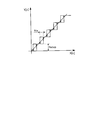
- FIG. 14 is a diagram illustrating an example of an operation state of the quantization unit.
- the quantization units 64 and 65 are filters having input / output characteristics as shown in FIG. 14, for example.
- the output Y [n] is quantized to an integer multiple of Nstep.
- a hysteresis (His) characteristic is provided to prevent chattering with respect to the input X [n]. Although it is not necessary to provide this hysteresis characteristic, it is recommended to provide the hysteresis characteristic from the viewpoint of reducing the number of operations, which is the purpose of quantization.
- FIG. 8 The other parts of FIG. 8 are omitted because they have already been described in the first embodiment. Moreover, although already demonstrated in Embodiment 1, either one may be sufficient as the upper / lower limit restriction
- the limited operation signal MV2 [n] to the control target 2 changes only in Nstep units.
- the quantizing unit 64 is considered to be the same type of filter as the upper / lower limit limiting unit 61 and the change rate limiting unit 62, it may be considered that the quantizing unit 65 is unnecessary.
- the quantizing unit 65 is omitted, the operation signal MV [n] and the limited operation signal MV2 [n] are always different, which is equivalent to the occurrence of a deviation.
- the previous overintegration removal through the quantizing unit 64 and the subtracting unit 63 always works, and as a result, it operates only with a resolution of Nstep units. Therefore, the deviation signal ⁇ [n] is assumed to be other than “0” only when deviation occurs in the upper / lower limit restriction unit 61 and the change rate restriction unit 62 by providing the quantization unit 65.
- the operation signal MV [n] and the output of the change rate limiting unit 62 have the same value. Therefore, the values input to the quantization unit 64 and the quantization unit 65 are equal. Further, since the quantization unit 64 and the quantization unit 65 have the same configuration, the limited operation signal MV2 [n] that is the output of the quantization unit 64 and the output of the quantization unit 65 are also equal.
- the subtracting unit 63 subtracts the limited operation signal MV2 [n] from the output of the quantizing unit 65, and the value is converted into the limit deviation signal ⁇ [ n].
- the quantizing unit 64 that obtains the restricted operation signal MV2 [n] and outputs it to the controlled object 2 and the same limiting value as that of the quantizing unit 64 is obtained. Since the quantization unit 65 that quantizes the held operation signal MV [n] by limiting the value that can be taken to a range that is an integral multiple of a predetermined value, the output to the control target 2 is changed stepwise. The operation frequency of the controlled object 2 can be lowered. As a result, the control object 2 can be further used for a long time, improved in durability, reduced in energy consumption, improved in safety, and reduced in maintenance costs.
- Embodiment 5 FIG. Compared with the adjusting device 1 according to the fourth embodiment, the adjusting device 1 according to the fifth embodiment is provided with a higher priority function.
- the related diagrams are FIG. 9, FIG. 2 and FIG.
- FIG. 9 is a diagram illustrating an example of the configuration of the adjusting device according to the fifth embodiment.
- the role of the adjusting device 1 is to provide a limited operation signal MV2 [output to the control target 2 so as to make the process value PV of the control target 2 coincide with the higher target value of the target value SV and the minimum guaranteed target value LV. n].
- an output below the minimum guaranteed operation signal M2 [n] calculated from the minimum guaranteed target value LV is not performed, and is always set to the minimum guaranteed operation signal M2 [n] or higher.
- SV is given by manual operation
- LV is a protection command given from the security device.
- the adjusting device operates to guarantee the minimum process value corresponding to the LV, but even if the output is excessive in M2 [n] simply calculated from the LV, the limited operation signal Do not adjust the direction to reduce
- the adjustment device 1 according to the fifth embodiment is selected by performing higher priority selection processing of a target value SV and a minimum guaranteed target value LV given from a host system (not shown) than the adjustment device 1 of the first embodiment.
- a maximum value selection unit 17 as a first maximum value selection unit that outputs the target value to the adjustment calculation unit 14, and an SVMV conversion unit 18 that converts the minimum guarantee target value LV into the minimum guarantee operation signal M2 [n].
- the output limiting unit 15 outputs a second maximum value for performing high-order priority selection processing of the operation signal MV [n] and the minimum guaranteed operation signal M2 [n] from the adjustment calculation unit 14 to the output to the controlled object 2.
- a maximum value selection unit 66 as a selection unit is added.
- the SVMV conversion unit 18 performs conversion from a target value to an operation signal determined from the specification of the control target 2.
- A1 and B1 are constants determined from the specification of the control target 2.
- a linear expression is used, but any function may be used according to the control object 2.
- the maximum value selection unit 17 selects a larger value from SV [n] and LV [N].
- the maximum value selection unit 66 selects a larger value from the outputs of M2 [n] and the change rate limiting unit 62, and outputs the selected value to the quantization unit 64.
- the upper / lower limit limiting unit 61 and the change rate limiting unit 62 included in the output limiting unit 15 may be either one or both, or the order may be changed.
- the quantizing units 64 and 65 may exist together or may not exist together.
- the maximum value selection unit 66 When the maximum value selection unit 17 is not provided, the maximum value selection unit 66 outputs the minimum guaranteed operation signal M2 [n] with priority, but the difference between the target value SV and the minimum guaranteed target value LV is large. In this case, since the deviation e [n] occurs, the operation signal MV [n] from the adjustment calculation unit 14 is fixed to the lower side. Therefore, the operation signal MV [n] from the adjustment calculation unit 14 does not act effectively. In order to operate effectively, by providing the maximum value selection unit 17, the target value SV [n] input to the adjustment calculation unit 14 needs to be subjected to high priority processing.
- the maximum value selection unit 17, the SVMV conversion unit 18, and the maximum value selection unit 66 are provided, but the minimum guarantee operation is performed, but the operation is insufficient.
- the adjustment operation can be effectively performed by the operation signal MV [n] of the adjustment calculation unit 14. As a result, it is possible to safely perform a high priority operation required when linking with a security device or the like.
- Embodiment 6 FIG. Compared to the fifth embodiment, the sixth embodiment is further equipped with a manual switching function. It is generally a common requirement that manual operation as well as automatic adjustment is possible. Here, a solution for such a case is provided.
- FIG. 9 is a diagram illustrating an example of the configuration of the adjusting device 1 according to the sixth embodiment. Only the parts different from the fifth embodiment will be described. The related diagrams are FIG. 9, FIG. 2 and FIG. 10 (only the part where FIG. 3 becomes FIG. 10 is different).
- the adjustment device 1 includes an SVMV conversion unit 18 that converts the current target value SV [n] to the manual operation signal M1 [n] as compared with the adjustment device 1 according to the fifth embodiment.
- the adjustment calculation unit 14 includes a subtraction unit 27 that performs a calculation based on a manual operation signal M1 [n] ⁇ an operation signal MV [n ⁇ 1] of the previous control period in response to a manual switching signal Manu.
- An M / A changeover switch 28 for switching the speed type adjustment signal ⁇ MV [n] to a predetermined signal calculated by the subtractor 27 is added.
- the SVMV conversion unit 18 performs conversion from a target value to an operation signal determined from the specification of the control target 2.
- A1 and B1 are constants determined from the specifications of the control target 2.
- a linear expression is used, but any function may be used according to the control object 2.
- FIG. 10 is a diagram illustrating an example of the configuration of the adjustment calculation unit according to the sixth embodiment.
- the difference from the fifth embodiment is that when the manual switching signal Manu is input and the manual switching signal Manu is on (manual operation), the second speed form adjustment signal ⁇ MV [n] is changed to M1 [n]. This is the point of switching to -MV [n-1].
- the operation signal MV [n] always matches M1 [n] during manual operation.
- a predetermined switch (not shown) for switching the output of the integrator 24 (operation signal MV [n]) to M1 [n] may be further provided.
- 10 performs M / A switching between the output of the operation M1 [n] ⁇ MV [n ⁇ 1] performed by the subtractor 27 and the signal output from the adder 23.
- the switch 28 is used for switching.
- the adjustment device includes the SVMV conversion unit 18 and the function of switching the input of the integrator to the manual operation signal-the operation signal in the previous control cycle during manual operation.
- Balanceless bumpless switching is possible.
- balanceless means that there is no need to switch after waiting for the process value PV and the target value SV to be balanced.
- the bumpless means that there is no operation in which the operation signal MV [n] changes suddenly at the moment of switching and the process value PV fluctuates. As a result, it is possible to improve the controllability of the controlled object 2 as compared with the conventional adjusting device.
- Embodiment 7 FIG. Compared to the sixth embodiment, the seventh embodiment corresponds to the position-type adjusting unit.
- FIG. 9 is a diagram illustrating an example of the configuration of the adjusting device 1 according to the seventh embodiment. Only the parts different from the sixth embodiment will be described. The related diagrams are FIG. 9, FIG. 2 and FIG. 11 (only the part where FIG. 10 becomes FIG. 11 is different).
- FIG. 11 is a diagram illustrating an example of a configuration of an adjustment calculation unit according to the seventh embodiment.
- the difference from the second embodiment is that when the manual switching signal Manu is input and the manual switching signal Manu is on, the input of the integrator 43 is M1 [n] ⁇ MV [n ⁇ 1] ⁇ (MVP [ n] + MVD [n]).
- the operation signal MV [n] always matches M1 [n].
- a predetermined switch (not shown) for switching the output of the integrator 43 (operation signal MV [n]) to M1 [n] may be further provided.
- the adjustment calculation unit 14 shown in FIG. 11 outputs the signal M1 [n] ⁇ MV [n ⁇ 1] ⁇ (MVP [n] + MVD [n]) performed by the subtraction unit 37 and the subtraction unit 42. These signals are switched by the M / A switch 44.
- the adjustment apparatus concerning each embodiment demonstrated to the example the adjustment apparatus which controls the deceleration of a railcar, if it is an adjustment apparatus or control system provided with an I adjustment calculating part and an output restriction part, Applicable.
- the present invention can be variously modified and implemented without departing from the spirit of the present invention.
- the adjusting device according to the present invention is useful for various adjusting devices, control devices, and control systems including an adjusting device that controls the deceleration of a railway vehicle, an I adjustment calculation unit, and an output limiting unit. .
Landscapes
- Physics & Mathematics (AREA)
- General Physics & Mathematics (AREA)
- Engineering & Computer Science (AREA)
- Automation & Control Theory (AREA)
- Feedback Control In General (AREA)
Abstract
Description
2 制御対象
11,12 入力部
13 偏差演算部
14 調節演算部
15 出力制限部
16 過積分算出部
17 最大値選択部(第1の最大値選択部)
18 SVMV変換部
21 速度形I調節部(速度形積分調節部)
22 速度形PD調節部
23,34 加算部
24,43 積分器
26,36,91,92 記憶部
27,37,42,52,63 減算部
28,44 M/A切換スイッチ
31 位置形I調節部(位置形積分調節部)
32 位置形PD調節部
41,54 ゲイン部
51 フィードバックゲイン部
53 ゲイン付き積分器
60 直列に接続された一つ以上の制限要素
61 上下限制限部
62 変化率制限部
64,65 量子化部
66 最大値選択部(第2の最大値選択部)
71,72,81,82 操作信号状態
93 絶対値最小値選択部
SV 目標値
SV[n] 現在の目標値
PV プロセス値
PV[n] 現在のプロセス値
e[n] 偏差
ΔI[n] 速度形I調節信号(速度形積分調節信号)
ΔI[n-1] 前回速度形I調節信号
MV[n] 操作信号
MV2[n] 制限付き操作信号
ARW[n] 前回過積分信号
δ[n] 制限逸脱信号
δ[n-1] 前回制限逸脱信号
ΔP[n]+ΔD[n] 速度形P+D調節信号
ΔMV[n] 速度形調節信号
MVI[n] 位置形I調節信号(位置形積分調節信号)
MVP[n]+MVD[n] 位置形P+D調節信号
Manu マニュアル切換信号
LV 最低保証目標値
LV[n] 現在の最低保証目標値
M1[n] マニュアル操作信号
M2[n] 最低保証操作信号
図1は、実施の形態1にかかる調節装置の構成の一例を示す図である。調節装置1の役割は、目標値SV(設定値ともいう)と制御対象2のプロセス値PV(測定値ともいう)を一致させるように、制御対象2への出力である制限付き操作信号MV2[n]を調節することである。関連図は、図1、図2、図3、図7である。
実施の形態1にかかる調節装置1は、調節演算部14や速度形I調節部21を始めとする調節部で構成したが、実施の形態2にかかる調節装置1では、位置形積分調節部である位置形I調節部31を始めとする調節部で構成する。実施の形態1と異なっている部分のみ説明する。関連図は、図1、図2、図4、図5、図7である(図3が、図4、図5になっているところのみ異なる)。
実施の形態2にかかる調節装置1の位置形I調節部31の構成が少し異なる実施の形態3について示す。実施の形態2と異なっている部分のみ説明する。関連図は、図1、図2、図4、図6、図7である(図5が、図6になっているところのみ異なる)。この構成は、一般的な積分器がゲイン付きであり、その前後に修正を加えるだけで、前回過積分を除去可能な構成を得ようとするものである。もしゲイン部と積分器が分離している構成の積分器を用いるなら実施の形態2の構成を推奨する。
実施の形態4にかかる調節装置は、制限付き操作信号MV2[n]を量子化することにより、制御対象2への出力をステップ状にし、制御対象2の動作頻度を下げ、制御対象2の更なる長期使用化および消費電力を低減することができるように構成されている。実施の形態1と異なっている部分のみ説明する。関連図は、図1、図2、図3、図8、図14である(図7が、図8になっている部分のみ異なる)。
実施の形態4にかかる調節装置1に比べ、高位優先機能を追加したのが、実施形態5にかかる調節装置1である。関連図は図9、図2、図3である。
実施の形態5に比べ、さらに、マニュアル切換機能を装備したのが、実施の形態6である。自動調節だけでなく、マニュアル操作が可能であることは、一般的に良くある要求事項である。ここでは、そのようなケースの解決方法を提供する。
実施の形態6に比べ、さらに、位置形の調節部に対応したのが、実施の形態7である。
Claims (13)
- 制御対象からのプロセス値を目標値に一致させるように操作信号を演算出力する調節演算部と、前記調節演算部からの前記操作信号を制限して前記制御対象へ出力する出力制限部とを備える調節装置において、
前記調節演算部は、少なくとも速度形積分調節部または位置形積分調節部を含み、
前記出力制限部は、所定の制限からの逸脱具合を示す制限逸脱信号を出力する機能を備え、
前記調節演算部から出力された速度形積分調節信号と前記制限逸脱信号とに基づいて、前回制御周期に発生した前回過積分に相当する前回過積分信号を算出する過積分算出部を備え、
前記調節演算部は、前記前回過積分信号により、自身が保存している積分値を補正することにより、前記前回過積分を除去する機能を備えること、
を特徴とする調節装置。 - 前記過積分算出部は、
前回制御周期における前記制限逸脱信号および前回制御周期における前記速度形積分調節信号から、これら両信号の符号が異符号の場合には「0」を、同符号の場合にはこれらの両信号のうちで絶対値の小さいものを選択し、前回過積分信号を算出することを特徴とする請求項1に記載の調節装置。 - 前記調節演算部は、
偏差に基づいて速度形積分調節信号を出力する速度形積分調節部と、
偏差に基づいて、第1の速度形調節信号を出力する前記速度形積分調節部以外の速度形調節部と、
前記速度形積分調節信号+前記第1の速度形調節信号-前記前回過積分信号なる演算により、第2の速度形調節信号を得る加算部と、
前記第2の速度形調節信号を位置形信号である操作信号に変換する積分器と、
を備えたことを特徴とする請求項1に記載の調節装置。 - 前記調節演算部は、
偏差に基づいて速度形積分調節信号および位置形積分調節信号を出力すると共に、前記前回過積分信号により自身が保存している積分値を補正する位置形積分調節部と、
前記位置形積分調節部以外の位置形調節部と、
前記位置形積分調節部以外の位置形調節部から出力された第1の位置形調節信号を前記位置形積分調節信号に加え第2の位置形調節信号を算出し、前記第2の位置形調節信号を操作信号として出力する加算部と、
を備えたことを特徴とする請求項1に記載の調節装置。 - 前記位置形積分調節部は、
目標値からプロセス値を減じた偏差に所定のゲインを乗ずることにより速度形積分調節信号を出力するゲイン部を備え、
前記速度形積分調節信号から前記前回過積分信号を減じた信号を積分することにより位置形積分調節信号を求めることを特徴とする請求項4に記載の調節装置。 - 前記位置形積分調節部は、
目標値からプロセス値を減じた偏差に所定の積分ゲインを乗ずることにより速度形積分調節信号を出力するゲイン部と、
前記偏差から、前記前回過積分信号に前記所定の積分ゲインの逆数を乗じた信号を減ずる減算部と、
前記減算部の出力を取り込み、前記所定の積分ゲインを乗ずると共に積分演算を行い、位置形積分調節信号を出力するゲイン付き積分器と、
を備えたことを特徴とする請求項4に記載の調節装置。 - 前記出力制限部は、
前記操作信号を受け、制限付き操作信号を前記制御対象に出力する直列に接続された1つ以上の制限要素と、
前記操作信号から前記制限付き操作信号を減ずることにより制限逸脱信号を求め、前記過積分算出部へ出力する減算部と、
を備えたことを特徴とする請求項1に記載の調節装置。 - 前記出力制限部は、
前記操作信号を制限して出力する、直列に接続された1つ以上の制限要素と、
前記直列に接続された1つ以上の制限要素の出力信号の取り得る値を所定値の整数倍の範囲に制限して量子化し、量子化された操作信号を前記制御対象へ出力する第1の量子化部と、
前記操作信号を受け、前記第1の量子化部と同一の条件にて量子化し、量子化された操作信号を出力する第2の量子化部と、
前記第2の量子化部の出力から第1の量子化部の出力を減ずることにより制限逸脱信号を求め、前記過積分算出部へ出力する減算部と、
を備えたことを特徴とする請求項1に記載の調節装置。 - 前記調節装置は、
上位システムから与えられる目標値と最低保証目標値との高位優先選択処理を行い、選択された目標値を調節演算部に出力する第1の最大値選択部と、
最低保証目標値から最低保証操作信号に変換するSVMV変換部と、
少なくとも、前記直列に接続された1つ以上の制限要素の入力信号と前記最低保証操作信号との高位優先選択処理をして出力する第2の最大値選択部を含む出力制限部と、
を備えたことを特徴とする請求項7または8に記載の調節装置。 - 前記直列に接続された1つ以上の制限要素には、
少なくとも入力信号の大きさを所定の範囲に制限して出力する上下限制限部を含むことを特徴とする請求項7~9のいずれか1つに記載の調節装置。 - 前記直列に接続された1つ以上の制限要素には、
少なくとも入力信号の変化率を所定の範囲内に制限して出力する変化率制限部を含むことを特徴とする請求項7~9のいずれか1つに記載の調節装置。 - 目標値からマニュアル操作信号に変換するSVMV変換部を備え、
前記調節演算部は、
少なくとも、マニュアル切換信号により、マニュアル操作時は、マニュアル操作信号-前回演算周期における操作信号なる演算を行う減算部を備え、前記第2の速度形調節信号を前記減算部で演算された所定の信号に切換えることを特徴とする請求項3に記載の調節装置。 - 目標値からマニュアル操作信号に変換するSVMV変換部を備え、
前記調節演算部は、
少なくとも、マニュアル切換信号により、マニュアル操作時は、マニュアル操作信号-前回制御周期における操作信号-前記第1の位置形調節信号なる演算を行う減算部を備え、前記第2の位置形調節信号を前記減算部で演算された所定の信号に切換えることを特徴とする請求項5に記載の調節装置。
Priority Applications (10)
| Application Number | Priority Date | Filing Date | Title |
|---|---|---|---|
| EP08877286.8A EP2336833B1 (en) | 2008-10-10 | 2008-10-10 | Adjuster |
| JP2009517211A JP4383526B1 (ja) | 2008-10-10 | 2008-10-10 | 調節装置 |
| CA2740050A CA2740050C (en) | 2008-10-10 | 2008-10-10 | Regulator with output limiting section |
| KR1020117006743A KR20110044329A (ko) | 2008-10-10 | 2008-10-10 | 조절 장치 |
| US13/060,385 US20110160943A1 (en) | 2008-10-10 | 2008-10-10 | Regulator |
| MX2011003622A MX2011003622A (es) | 2008-10-10 | 2008-10-10 | Regulador. |
| PCT/JP2008/068499 WO2010041338A1 (ja) | 2008-10-10 | 2008-10-10 | 調節装置 |
| CN200880131594.2A CN102177473B (zh) | 2008-10-10 | 2008-10-10 | 调节装置 |
| AU2008362695A AU2008362695B2 (en) | 2008-10-10 | 2008-10-10 | Adjuster |
| TW097143800A TWI379177B (en) | 2008-10-10 | 2008-11-13 | Signal control device |
Applications Claiming Priority (1)
| Application Number | Priority Date | Filing Date | Title |
|---|---|---|---|
| PCT/JP2008/068499 WO2010041338A1 (ja) | 2008-10-10 | 2008-10-10 | 調節装置 |
Publications (1)
| Publication Number | Publication Date |
|---|---|
| WO2010041338A1 true WO2010041338A1 (ja) | 2010-04-15 |
Family
ID=41549771
Family Applications (1)
| Application Number | Title | Priority Date | Filing Date |
|---|---|---|---|
| PCT/JP2008/068499 Ceased WO2010041338A1 (ja) | 2008-10-10 | 2008-10-10 | 調節装置 |
Country Status (10)
| Country | Link |
|---|---|
| US (1) | US20110160943A1 (ja) |
| EP (1) | EP2336833B1 (ja) |
| JP (1) | JP4383526B1 (ja) |
| KR (1) | KR20110044329A (ja) |
| CN (1) | CN102177473B (ja) |
| AU (1) | AU2008362695B2 (ja) |
| CA (1) | CA2740050C (ja) |
| MX (1) | MX2011003622A (ja) |
| TW (1) | TWI379177B (ja) |
| WO (1) | WO2010041338A1 (ja) |
Cited By (3)
| Publication number | Priority date | Publication date | Assignee | Title |
|---|---|---|---|---|
| JP2013163237A (ja) * | 2012-02-10 | 2013-08-22 | Seiko Epson Corp | モーター制御装置、ロボットハンド、ロボット及びモーター制御方法 |
| JP2015102314A (ja) * | 2013-11-27 | 2015-06-04 | 三浦工業株式会社 | ボイラシステム |
| JP2017134769A (ja) * | 2016-01-29 | 2017-08-03 | オムロン株式会社 | 信号処理装置、信号処理方法、情報処理プログラム、および記録媒体 |
Families Citing this family (4)
| Publication number | Priority date | Publication date | Assignee | Title |
|---|---|---|---|---|
| JP6346582B2 (ja) * | 2015-03-26 | 2018-06-20 | アズビル株式会社 | 制御装置および制御方法 |
| US9517772B1 (en) | 2015-05-27 | 2016-12-13 | Caterpillar Inc. | Electronic speed control for locomotives |
| US10279823B2 (en) * | 2016-08-08 | 2019-05-07 | General Electric Company | System for controlling or monitoring a vehicle system along a route |
| CN115291499B (zh) * | 2022-06-21 | 2026-04-14 | 中国大唐集团科学技术研究总院有限公司华东电力试验研究院 | 一种取小值控制方法和控制系统 |
Citations (6)
| Publication number | Priority date | Publication date | Assignee | Title |
|---|---|---|---|---|
| JPH02213902A (ja) * | 1989-02-15 | 1990-08-27 | Yokogawa Electric Corp | ロボットの制御装置 |
| JPH07219601A (ja) * | 1994-02-02 | 1995-08-18 | Toshiba Corp | 調節装置 |
| JP2531796B2 (ja) | 1989-07-07 | 1996-09-04 | 株式会社東芝 | 調節装置 |
| JP2000155602A (ja) * | 1998-11-19 | 2000-06-06 | Rkc Instrument Inc | 制御装置 |
| JP2004086858A (ja) * | 2002-06-26 | 2004-03-18 | Omron Corp | 制御装置、温度調節器および熱処理装置 |
| JP2004206515A (ja) * | 2002-12-26 | 2004-07-22 | Rkc Instrument Inc | 制御装置 |
Family Cites Families (5)
| Publication number | Priority date | Publication date | Assignee | Title |
|---|---|---|---|---|
| US3938017A (en) * | 1974-03-05 | 1976-02-10 | Johnson Service Company | Anti-reset windup proportional and integral controller |
| US4268784A (en) * | 1977-07-22 | 1981-05-19 | Phillips Petroleum Company | Control method and apparatus with reset windup prevention |
| US4303873A (en) * | 1980-06-27 | 1981-12-01 | Honeywell Inc. | Reset windup limiting |
| SE9401847L (sv) * | 1994-05-30 | 1995-05-22 | Saab Scania Ab | Metod och anordning för att utföra faskompensering i ett fordons styrsystem |
| US6939346B2 (en) * | 1999-04-21 | 2005-09-06 | Oratec Interventions, Inc. | Method and apparatus for controlling a temperature-controlled probe |
-
2008
- 2008-10-10 WO PCT/JP2008/068499 patent/WO2010041338A1/ja not_active Ceased
- 2008-10-10 US US13/060,385 patent/US20110160943A1/en not_active Abandoned
- 2008-10-10 EP EP08877286.8A patent/EP2336833B1/en active Active
- 2008-10-10 CN CN200880131594.2A patent/CN102177473B/zh active Active
- 2008-10-10 MX MX2011003622A patent/MX2011003622A/es active IP Right Grant
- 2008-10-10 AU AU2008362695A patent/AU2008362695B2/en not_active Ceased
- 2008-10-10 KR KR1020117006743A patent/KR20110044329A/ko not_active Ceased
- 2008-10-10 JP JP2009517211A patent/JP4383526B1/ja active Active
- 2008-10-10 CA CA2740050A patent/CA2740050C/en not_active Expired - Fee Related
- 2008-11-13 TW TW097143800A patent/TWI379177B/zh not_active IP Right Cessation
Patent Citations (6)
| Publication number | Priority date | Publication date | Assignee | Title |
|---|---|---|---|---|
| JPH02213902A (ja) * | 1989-02-15 | 1990-08-27 | Yokogawa Electric Corp | ロボットの制御装置 |
| JP2531796B2 (ja) | 1989-07-07 | 1996-09-04 | 株式会社東芝 | 調節装置 |
| JPH07219601A (ja) * | 1994-02-02 | 1995-08-18 | Toshiba Corp | 調節装置 |
| JP2000155602A (ja) * | 1998-11-19 | 2000-06-06 | Rkc Instrument Inc | 制御装置 |
| JP2004086858A (ja) * | 2002-06-26 | 2004-03-18 | Omron Corp | 制御装置、温度調節器および熱処理装置 |
| JP2004206515A (ja) * | 2002-12-26 | 2004-07-22 | Rkc Instrument Inc | 制御装置 |
Non-Patent Citations (1)
| Title |
|---|
| See also references of EP2336833A4 |
Cited By (3)
| Publication number | Priority date | Publication date | Assignee | Title |
|---|---|---|---|---|
| JP2013163237A (ja) * | 2012-02-10 | 2013-08-22 | Seiko Epson Corp | モーター制御装置、ロボットハンド、ロボット及びモーター制御方法 |
| JP2015102314A (ja) * | 2013-11-27 | 2015-06-04 | 三浦工業株式会社 | ボイラシステム |
| JP2017134769A (ja) * | 2016-01-29 | 2017-08-03 | オムロン株式会社 | 信号処理装置、信号処理方法、情報処理プログラム、および記録媒体 |
Also Published As
| Publication number | Publication date |
|---|---|
| JP4383526B1 (ja) | 2009-12-16 |
| MX2011003622A (es) | 2011-06-16 |
| EP2336833A4 (en) | 2012-04-18 |
| JPWO2010041338A1 (ja) | 2012-03-01 |
| KR20110044329A (ko) | 2011-04-28 |
| AU2008362695B2 (en) | 2013-09-12 |
| TW201015253A (en) | 2010-04-16 |
| CA2740050A1 (en) | 2010-04-15 |
| TWI379177B (en) | 2012-12-11 |
| EP2336833A1 (en) | 2011-06-22 |
| EP2336833B1 (en) | 2013-06-12 |
| CN102177473B (zh) | 2014-07-30 |
| US20110160943A1 (en) | 2011-06-30 |
| CA2740050C (en) | 2015-01-20 |
| CN102177473A (zh) | 2011-09-07 |
| AU2008362695A2 (en) | 2011-05-12 |
| AU2008362695A1 (en) | 2010-04-15 |
Similar Documents
| Publication | Publication Date | Title |
|---|---|---|
| JP4383526B1 (ja) | 調節装置 | |
| JP5689704B2 (ja) | モータ制御装置およびモータ制御方法 | |
| Plestan et al. | A new algorithm for high‐order sliding mode control | |
| KR20130030263A (ko) | 모터 제어 장치 | |
| JP5825953B2 (ja) | 電気機械フライトアクチュエーションシステムの多重速度コントローラのための統合型アップサンプラー及びフィルタリング | |
| JP5043963B2 (ja) | 車両用ブレーキのトルク補正が可能な制御方法 | |
| US20100171458A1 (en) | Servo controller | |
| JP2004211669A (ja) | サーボ弁制御装置およびサーボ弁制御システムの異常検出装置 | |
| JP2010170524A (ja) | システムを制御するためのコントローラおよびコントローラを有するシステムを制御する方法 | |
| JP3850363B2 (ja) | モータの位置制御装置 | |
| US20090024290A1 (en) | Method of controlling a vehicle brake with torque correction | |
| JP5388604B2 (ja) | モータ駆動制御装置 | |
| JP5250215B2 (ja) | 偏差補償プログラム | |
| JP2008181452A (ja) | 制御装置 | |
| JP3772340B2 (ja) | バルブポジショナ | |
| Chalanga et al. | Third order sliding mode control with a predefined convergence time: application to an electropneumatic actuator | |
| JP3765371B2 (ja) | バルブポジショナ | |
| EP2180386A1 (en) | Control device and method for operating a control device | |
| JP5192225B2 (ja) | 半導体電力変換装置 | |
| JP2007306779A (ja) | モータ制御装置 | |
| JP5691635B2 (ja) | モータ制御装置 | |
| KR101732415B1 (ko) | 비행기 제어장치 및 제어방법 | |
| JPH07210203A (ja) | むだ時間補償制御装置 | |
| JPS5872202A (ja) | アナログ式制御器の出力制限回路 | |
| JP2017198266A (ja) | 変速機制御装置 |
Legal Events
| Date | Code | Title | Description |
|---|---|---|---|
| WWE | Wipo information: entry into national phase |
Ref document number: 200880131594.2 Country of ref document: CN |
|
| WWE | Wipo information: entry into national phase |
Ref document number: 2009517211 Country of ref document: JP |
|
| 121 | Ep: the epo has been informed by wipo that ep was designated in this application |
Ref document number: 08877286 Country of ref document: EP Kind code of ref document: A1 |
|
| WWE | Wipo information: entry into national phase |
Ref document number: 2008362695 Country of ref document: AU |
|
| ENP | Entry into the national phase |
Ref document number: 2008362695 Country of ref document: AU Date of ref document: 20081010 Kind code of ref document: A |
|
| ENP | Entry into the national phase |
Ref document number: 20117006743 Country of ref document: KR Kind code of ref document: A |
|
| WWE | Wipo information: entry into national phase |
Ref document number: 2008877286 Country of ref document: EP |
|
| WWE | Wipo information: entry into national phase |
Ref document number: MX/A/2011/003622 Country of ref document: MX |
|
| WWE | Wipo information: entry into national phase |
Ref document number: 2740050 Country of ref document: CA |
|
| NENP | Non-entry into the national phase |
Ref country code: DE |