WO2010041506A1 - タービンロータ及びタービンロータの製造方法 - Google Patents
タービンロータ及びタービンロータの製造方法 Download PDFInfo
- Publication number
- WO2010041506A1 WO2010041506A1 PCT/JP2009/063137 JP2009063137W WO2010041506A1 WO 2010041506 A1 WO2010041506 A1 WO 2010041506A1 JP 2009063137 W JP2009063137 W JP 2009063137W WO 2010041506 A1 WO2010041506 A1 WO 2010041506A1
- Authority
- WO
- WIPO (PCT)
- Prior art keywords
- steel
- rotor
- rotor material
- temperature
- low
- Prior art date
- Legal status (The legal status is an assumption and is not a legal conclusion. Google has not performed a legal analysis and makes no representation as to the accuracy of the status listed.)
- Ceased
Links
Images




Classifications
-
- F—MECHANICAL ENGINEERING; LIGHTING; HEATING; WEAPONS; BLASTING
- F01—MACHINES OR ENGINES IN GENERAL; ENGINE PLANTS IN GENERAL; STEAM ENGINES
- F01D—NON-POSITIVE DISPLACEMENT MACHINES OR ENGINES, e.g. STEAM TURBINES
- F01D5/00—Blades; Blade-carrying members; Heating, heat-insulating, cooling or antivibration means on the blades or the members
- F01D5/02—Blade-carrying members, e.g. rotors
- F01D5/06—Rotors for more than one axial stage, e.g. of drum or multiple disc type; Details thereof, e.g. shafts, shaft connections
- F01D5/063—Welded rotors
-
- B—PERFORMING OPERATIONS; TRANSPORTING
- B23—MACHINE TOOLS; METAL-WORKING NOT OTHERWISE PROVIDED FOR
- B23K—SOLDERING OR UNSOLDERING; WELDING; CLADDING OR PLATING BY SOLDERING OR WELDING; CUTTING BY APPLYING HEAT LOCALLY, e.g. FLAME CUTTING; WORKING BY LASER BEAM
- B23K35/00—Rods, electrodes, materials, or media, for use in soldering, welding, or cutting
- B23K35/22—Rods, electrodes, materials, or media, for use in soldering, welding, or cutting characterised by the composition or nature of the material
- B23K35/24—Selection of soldering or welding materials proper
- B23K35/30—Selection of soldering or welding materials proper with the principal constituent melting at less than 1550°C
-
- C—CHEMISTRY; METALLURGY
- C21—METALLURGY OF IRON
- C21D—MODIFYING THE PHYSICAL STRUCTURE OF FERROUS METALS; GENERAL DEVICES FOR HEAT TREATMENT OF FERROUS OR NON-FERROUS METALS OR ALLOYS; MAKING METAL MALLEABLE, e.g. BY DECARBURISATION OR TEMPERING
- C21D6/00—Heat treatment of ferrous alloys
- C21D6/002—Heat treatment of ferrous alloys containing Cr
-
- C—CHEMISTRY; METALLURGY
- C21—METALLURGY OF IRON
- C21D—MODIFYING THE PHYSICAL STRUCTURE OF FERROUS METALS; GENERAL DEVICES FOR HEAT TREATMENT OF FERROUS OR NON-FERROUS METALS OR ALLOYS; MAKING METAL MALLEABLE, e.g. BY DECARBURISATION OR TEMPERING
- C21D9/00—Heat treatment, e.g. annealing, hardening, quenching or tempering, adapted for particular articles; Furnaces therefor
- C21D9/28—Heat treatment, e.g. annealing, hardening, quenching or tempering, adapted for particular articles; Furnaces therefor for plain shafts
-
- C—CHEMISTRY; METALLURGY
- C21—METALLURGY OF IRON
- C21D—MODIFYING THE PHYSICAL STRUCTURE OF FERROUS METALS; GENERAL DEVICES FOR HEAT TREATMENT OF FERROUS OR NON-FERROUS METALS OR ALLOYS; MAKING METAL MALLEABLE, e.g. BY DECARBURISATION OR TEMPERING
- C21D9/00—Heat treatment, e.g. annealing, hardening, quenching or tempering, adapted for particular articles; Furnaces therefor
- C21D9/32—Heat treatment, e.g. annealing, hardening, quenching or tempering, adapted for particular articles; Furnaces therefor for gear wheels, worm wheels, or the like
-
- C—CHEMISTRY; METALLURGY
- C21—METALLURGY OF IRON
- C21D—MODIFYING THE PHYSICAL STRUCTURE OF FERROUS METALS; GENERAL DEVICES FOR HEAT TREATMENT OF FERROUS OR NON-FERROUS METALS OR ALLOYS; MAKING METAL MALLEABLE, e.g. BY DECARBURISATION OR TEMPERING
- C21D9/00—Heat treatment, e.g. annealing, hardening, quenching or tempering, adapted for particular articles; Furnaces therefor
- C21D9/50—Heat treatment, e.g. annealing, hardening, quenching or tempering, adapted for particular articles; Furnaces therefor for welded joints
-
- C—CHEMISTRY; METALLURGY
- C22—METALLURGY; FERROUS OR NON-FERROUS ALLOYS; TREATMENT OF ALLOYS OR NON-FERROUS METALS
- C22C—ALLOYS
- C22C38/00—Ferrous alloys, e.g. steel alloys
- C22C38/02—Ferrous alloys, e.g. steel alloys containing silicon
-
- C—CHEMISTRY; METALLURGY
- C22—METALLURGY; FERROUS OR NON-FERROUS ALLOYS; TREATMENT OF ALLOYS OR NON-FERROUS METALS
- C22C—ALLOYS
- C22C38/00—Ferrous alloys, e.g. steel alloys
- C22C38/04—Ferrous alloys, e.g. steel alloys containing manganese
-
- C—CHEMISTRY; METALLURGY
- C22—METALLURGY; FERROUS OR NON-FERROUS ALLOYS; TREATMENT OF ALLOYS OR NON-FERROUS METALS
- C22C—ALLOYS
- C22C38/00—Ferrous alloys, e.g. steel alloys
- C22C38/18—Ferrous alloys, e.g. steel alloys containing chromium
- C22C38/40—Ferrous alloys, e.g. steel alloys containing chromium with nickel
- C22C38/42—Ferrous alloys, e.g. steel alloys containing chromium with nickel with copper
-
- C—CHEMISTRY; METALLURGY
- C22—METALLURGY; FERROUS OR NON-FERROUS ALLOYS; TREATMENT OF ALLOYS OR NON-FERROUS METALS
- C22C—ALLOYS
- C22C38/00—Ferrous alloys, e.g. steel alloys
- C22C38/18—Ferrous alloys, e.g. steel alloys containing chromium
- C22C38/40—Ferrous alloys, e.g. steel alloys containing chromium with nickel
- C22C38/44—Ferrous alloys, e.g. steel alloys containing chromium with nickel with molybdenum or tungsten
-
- C—CHEMISTRY; METALLURGY
- C22—METALLURGY; FERROUS OR NON-FERROUS ALLOYS; TREATMENT OF ALLOYS OR NON-FERROUS METALS
- C22C—ALLOYS
- C22C38/00—Ferrous alloys, e.g. steel alloys
- C22C38/18—Ferrous alloys, e.g. steel alloys containing chromium
- C22C38/40—Ferrous alloys, e.g. steel alloys containing chromium with nickel
- C22C38/46—Ferrous alloys, e.g. steel alloys containing chromium with nickel with vanadium
-
- C—CHEMISTRY; METALLURGY
- C22—METALLURGY; FERROUS OR NON-FERROUS ALLOYS; TREATMENT OF ALLOYS OR NON-FERROUS METALS
- C22C—ALLOYS
- C22C38/00—Ferrous alloys, e.g. steel alloys
- C22C38/18—Ferrous alloys, e.g. steel alloys containing chromium
- C22C38/40—Ferrous alloys, e.g. steel alloys containing chromium with nickel
- C22C38/48—Ferrous alloys, e.g. steel alloys containing chromium with nickel with niobium or tantalum
-
- B—PERFORMING OPERATIONS; TRANSPORTING
- B23—MACHINE TOOLS; METAL-WORKING NOT OTHERWISE PROVIDED FOR
- B23K—SOLDERING OR UNSOLDERING; WELDING; CLADDING OR PLATING BY SOLDERING OR WELDING; CUTTING BY APPLYING HEAT LOCALLY, e.g. FLAME CUTTING; WORKING BY LASER BEAM
- B23K2101/00—Articles made by soldering, welding or cutting
- B23K2101/001—Turbines
-
- B—PERFORMING OPERATIONS; TRANSPORTING
- B23—MACHINE TOOLS; METAL-WORKING NOT OTHERWISE PROVIDED FOR
- B23K—SOLDERING OR UNSOLDERING; WELDING; CLADDING OR PLATING BY SOLDERING OR WELDING; CUTTING BY APPLYING HEAT LOCALLY, e.g. FLAME CUTTING; WORKING BY LASER BEAM
- B23K2103/00—Materials to be soldered, welded or cut
- B23K2103/02—Iron or ferrous alloys
- B23K2103/04—Steel or steel alloys
-
- Y—GENERAL TAGGING OF NEW TECHNOLOGICAL DEVELOPMENTS; GENERAL TAGGING OF CROSS-SECTIONAL TECHNOLOGIES SPANNING OVER SEVERAL SECTIONS OF THE IPC; TECHNICAL SUBJECTS COVERED BY FORMER USPC CROSS-REFERENCE ART COLLECTIONS [XRACs] AND DIGESTS
- Y10—TECHNICAL SUBJECTS COVERED BY FORMER USPC
- Y10T—TECHNICAL SUBJECTS COVERED BY FORMER US CLASSIFICATION
- Y10T29/00—Metal working
- Y10T29/49—Method of mechanical manufacture
- Y10T29/49316—Impeller making
- Y10T29/4932—Turbomachine making
Definitions
- the present invention relates to a turbine rotor and a method of manufacturing a turbine rotor, and more particularly to a turbine rotor and a method of manufacturing a turbine rotor suitable for use in a steam turbine.
- the rotor material is selected from the viewpoint of high temperature strength with respect to the temperature distribution in the steam turbine. Specifically, in a high temperature region exceeding 566 ° C., 10% Cr steel reinforced by containing 0.02% or more of nitrogen or 10% Cr steel (high Cr steel) containing W (tungsten) or the like is used In the middle range of 566 to 380 ° C., a low alloy steel of 1 to 2.25% CrMoV is used, and in the low temperature range of less than 380 ° C., a turbine rotor made of 3.5% NiCrMoV low alloy steel is used.
- an integrated turbine rotor made of high Cr steel having a strength corresponding to the high temperature region is used.
- the high Cr steel is a high cost material, and forming the entire turbine rotor used in an environment in which the high temperature region and the low temperature region coexist with the high Cr steel has a large cost burden. Therefore, it is used for a steam turbine in which a high temperature region and a low temperature region coexist in the steam turbine, and a turbine rotor portion disposed at a position where the environmental temperature in the steam turbine is a low temperature region is formed of inexpensive low alloy steel.
- Patent Document 1 discloses a turbine in which a high Cr steel rotor and a low Cr steel rotor are welded using a filler metal having a Cr steel content of 1.0 to 3.5% by mass as the dissimilar steel type welding rotor. A rotor is disclosed.
- Patent Document 1 in a turbine rotor in which a conventional high Cr steel rotor material and a low Cr steel rotor material are welded as disclosed in Patent Document 1, usually 0.02% by mass% to increase high temperature strength for high Cr steel
- the above nitrogen is contained, but when welding 10% Cr steel which is high Cr steel or 10% Cr steel containing W and low Cr steel, it is melted by nitrogen contained in the high Cr steel.
- minute blow holes easily occur in the material.
- a low Cr steel filler metal it has been confirmed that when a low Cr steel filler metal is used, the solubility of nitrogen in the filler metal is low because the content of Cr in the filler metal is low, and micro blow holes are likely to occur.
- the turbine rotor is a high-speed rotating body, and defects that are repeatedly fatigued are not tolerated, and even small blow holes become a problem when they gather, so a stable welded joint without blow holes is required.
- a dissimilar steel type rotor by welding a high temperature rotor material made of 12% Cr steel (10% Cr steel in a broad sense) and a low temperature rotor material made of low alloy steel, the high temperature rotor material is manufactured Forming an intermediate material by overlay welding of a suitable material, forming a high temperature rotor material having the intermediate material at high temperature, welding the low temperature rotor material to the intermediate material, and
- Patent Document 2 discloses a technique for manufacturing a dissimilar steel type rotor by performing a low temperature heat treatment on the entire of a high temperature rotor material and a low temperature rotor material.
- Patent Document 3 discloses a technology for manufacturing a dissimilar steel type rotor by welding a material and a low temperature rotor material and heat treating at 625 to 655 ° C. However, even in the technique disclosed in Patent Document 3, micro blow holes may occur.
- the present invention can produce a turbine rotor and a turbine rotor without blow holes without causing the cost of production to increase and the production time to be prolonged since the number of welding and heat treatments may be one. Intended to provide a method.
- the inventors have confirmed that the use of 9% Cr steel having a nitrogen content of 0.025% or less as a filler can prevent the occurrence of minute blow holes, and can solve the problem by a turbine rotor and A method of manufacturing a turbine rotor has been invented.
- the high-temperature rotor material is The filler metal for welding the high-temperature rotor material and the low-temperature rotor material, which is formed of high Cr steel having a nitrogen content of 0.02% or more by mass%, has a nitrogen content of 0.025% by mass It is characterized by being the following 9% Cr-based filler material.
- the high-temperature rotor material made of high Cr steel containing 0.02% or more of nitrogen and low Even when welding with a low temperature rotor material made of Cr steel, the generation of minute blow holes can be prevented. Furthermore, since there is no need for build-up welding, the number of times of welding and the number of heat treatments are also one, and the problems of rising production costs and prolonged production time do not occur. Further, the high temperature rotor material and the low temperature rotor material, which are formed of 2.25CrMoV steel and welded, are heat treated at 625 to 650 ° C. for 40 to 60 hours to form the high temperature rotor material.
- the Vickers hardness of the rotor material may be HV 350 or less.
- the creep rupture position of the dissimilar steel weld joint is the heat-affected zone of the fine grain structure that occurs on the low alloy steel side, and the creep strength is governed by the type of low alloy steel and the state of the fine grain structure. Therefore, sufficient creep strength can be secured by forming the low-temperature rotor material with 2.25 CrMoV steel, which is higher in creep strength than 1% Cr steel. Also, welding is performed using a 9% Cr-based filler metal having a nitrogen content of 0.025% or less by mass, heat treated at 625 to 650 ° C.
- the Vickers hardness of the high temperature rotor material By setting the value of HV to 350 or less, a suitable turbine rotor can be obtained without the occurrence of delayed cracking in the high temperature rotor. Further, the high temperature rotor material and the low temperature rotor material, which are formed of 3.5 NiCrMoV steel and welded, are heat-treated at 595 to 620 ° C. for 40 to 60 hours to form the high temperature rotor material.
- the Vickers hardness of the rotor material may be HV 350 or less.
- the low-temperature rotor material is formed of 3.5NiCrMoV steel, and is welded using a 9% Cr-based filler material having a nitrogen content of 0.025% or less by mass, and 40 to 50 ° C at 595 to 620 ° C.
- a turbine rotor capable of securing appropriate strength without delay cracking in the rotor for high temperature can be obtained.
- the manufacturing method of the turbine rotor for solving a subject In a method of manufacturing a turbine rotor in which a high-temperature rotor material made of high Cr steel and a low-temperature rotor material made of low Cr steel are welded and joined, the high-temperature rotor material has a nitrogen content of 0.
- the high-temperature rotor material and the low-temperature rotor material are joined by welding using a 9% Cr-based filler metal having a nitrogen content of 0.025% or less by mass%.
- the low-temperature rotor material is formed of 2.25CrMoV steel, and the high-temperature rotor material and the low-temperature rotor material are joined by welding, and then the high-temperature rotor material and the low-temperature rotor material are welded.
- the Vickers hardness of the rotor material for high temperature may be set to HV 350 or less by heat treatment at 650 ° C. for 40 to 60 hours.
- the low-temperature rotor material is formed of 3.5 NiCrMoV steel, and the high-temperature rotor material and the low-temperature rotor material are joined by welding, and then the high-temperature rotor material and the low-temperature rotor material are welded.
- the Vickers hardness of the rotor material for high temperature may be set to HV 350 or less by heat treatment at 620 ° C. for 40 to 60 hours.
- FIG. 1 is a cross-sectional view of a turbine rotor made in accordance with the present invention. It is an enlarged view of the welding part vicinity in FIG. It is a sectional view showing a joint in an example. It is a graph showing the influence of the alloying element on the solubility of N in molten iron at 1600 ° C. It is a characteristic view showing the creep rupture test result of a weld joint. It is a characteristic view showing hardness in a measurement point including a weld joint in an example. It is a characteristic view showing hardness in a measurement point including another weld joint in an example. It is a graph which shows Vickers hardness and a delayed crack generating area.
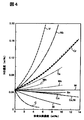
- FIG. 4 is a graph showing the effect of alloying elements on the solubility of N in molten iron at 1600 ° C. (Edited by The Iron and Steel Institute of Japan, third edition Iron and Steel Handbook Volume 1, Foundation (1981), P. 417).
- the horizontal axis represents the concentration of alloying elements (wt%) contained in the molten iron, and the vertical axis represents the solubility (wt%) of N. It can be understood from FIG. 4 that the solubility of N is higher as the Cr content in the molten iron is higher. If welding is performed with a Cr steel filler metal without welding the welded joints of high Cr steel and low alloy steel reinforced with 0.02% nitrogen by mass by mass, the high Cr steel side is The nitrogen contained for strengthening is dissolved in the filler, but the solubility of nitrogen in the filler depends on the content of Cr as shown in FIG.
- the solubility of nitrogen is low because the Cr content in the filler metal is low, and nitrogen exceeding the solubility becomes a gas, and nitrogen gas that could not escape from the molten pool during welding Is the blowhole. Therefore, it is necessary to use a filler material having a high Cr content, and a 9% Cr-based filler material having a Cr content close to that of the high Cr steel is used as the filler material. However, even when using a 9% Cr-based filler, minute blow holes may occur.
- FIG. 1 is a cross-sectional view of a turbine rotor manufactured according to the present invention
- FIG. 2 is an enlarged view of the vicinity of a weld 8 in FIG. As shown in FIG.
- high-temperature rotor material 4 made of 10% Cr steel which is high Cr steel or 10% Cr steel containing W, and 2.25% CrMoV steel or 3.5 NiCrMoV steel which is low Cr steel
- the high temperature rotor material 4 and the low temperature rotor are joined by, for example, arc welding using a 9% Cr-based filler material in which the low temperature rotor material 6 is butted and the nitrogen content is 0.025% or less by mass.
- a weld 10 is formed between the steel 6 and the steel 6.
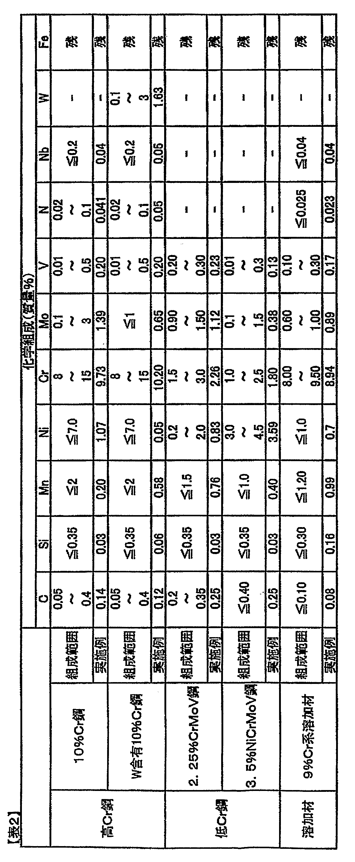
- 10% Cr steel or W containing 10% Cr steel used for the high temperature rotor material 4, 2.25% CrMoV steel or 3.5 NiCrMoV steel used for the low temperature rotor material 6, and 9% Cr additive filler As a material, for example, the composition range shown in Table 2 can be mentioned, and in the present example, the material of the composition of the example shown in Table 2 is used.
- the low-temperature rotor material 6 is 2.25 CrMoV steel
- the high-temperature rotor material has an Vickers hardness of HV 350 or less by performing heat treatment in a temperature range of 625 to 650 ° C. for 40 to 60 hours.
- Fig. 8 is a graph showing the Vickers hardness and the delayed cracking region (The Turbo Machinery Association 53rd Seminar Material (2001) "Regarding the Corrosion and Erosion of Steam Turbines" by Ito).
- the Turbo Machinery Association 53rd Seminar Material 2001
- Regarding the Corrosion and Erosion of Steam Turbines by Ito.
- Test piece 1 High temperature rotor material: 10% Cr steel, Low temperature rotor material: 2.25% CrMoV steel
- Test piece 2 High temperature rotor material: W containing 10% Cr steel, Low temperature rotor material: 2.25% CrMoV steel
- a test piece 3 a rotor material for high temperature: 10% Cr steel, a rotor material for low temperature: 1% CrMoV steel, and a creep test was conducted under the condition that the test temperature is constant.
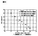
- the results are shown in FIG. In FIG. 5, the vertical axis represents stress, and the horizontal axis is a value determined in accordance with the creep test temperature and the rupture time. Since the creep test is performed under a constant test temperature, FIG. It is. As shown in FIG.
- the creep strength was improved more than the comparative example using 1% CrMoV steel as the low temperature rotor material.
- the hardness distribution of the test pieces 1 and 2 was measured. The results are shown in FIG. In FIG. 6, the vertical axis indicates the Vickers hardness HV, and the horizontal axis indicates the distance from the fixed point of the low temperature rotor material 6. As apparent from FIG. 6, the obtained weld joint is 10% Cr steel or 10% Cr steel containing W, its heat affected zone, welded portion, 2.25% CrMoV steel, any heat affected zone thereof It has been confirmed that the location also shows HV 350 or less. Furthermore, the hardness distribution of the following test pieces 4 was also measured in the same manner as the above test pieces 1 and 2.
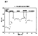
- Test specimen 4 rotor material for high temperature: 10% Cr steel, rotor material for low temperature: 3.5% NiCrMoV steel The results are shown in FIG. Also in the test piece 4, it was confirmed that HV 350 or less was shown at any location as in the test pieces 1 and 2. Moreover, 0.2% proof stress and tensile strength were measured about the said test piece 1,2,4. The results are shown in Table 3. Furthermore, the impact characteristics (absorbed energy at room temperature and 50% fracture transition temperature) of the heat-affected zone and the weld zone were examined. The results are shown in Table 4. In addition, the specification value in Table 3 and Table 4 represents the range which needs to be satisfied in order to use the manufactured turbine rotor without problem.
Landscapes
- Chemical & Material Sciences (AREA)
- Engineering & Computer Science (AREA)
- Mechanical Engineering (AREA)
- Materials Engineering (AREA)
- Metallurgy (AREA)
- Organic Chemistry (AREA)
- Physics & Mathematics (AREA)
- Thermal Sciences (AREA)
- Crystallography & Structural Chemistry (AREA)
- General Engineering & Computer Science (AREA)
- Turbine Rotor Nozzle Sealing (AREA)
- Arc Welding In General (AREA)
- Butt Welding And Welding Of Specific Article (AREA)
- Heat Treatment Of Articles (AREA)
Abstract
Description
しかしながら、前記高Cr鋼は高コスト材料であり、高温領域と中低温領域が共存する環境で使用されるタービンロータ全体を高Cr鋼で形成することはコスト面での負担が大きい。
そこで、蒸気タービン内で高温領域と中低温領域が共存する蒸気タービンに使用され、蒸気タービン内の環境温度が中低温領域である位置に配されるタービンロータ部位は安価な前記低合金鋼で形成し、蒸気タービン内の環境温度が高温領域である位置に配されるタービンロータ部位は高温強度に優れた前記高Cr鋼で形成した異鋼種溶接ロータが提案されている。
前記異鋼種溶接ロータとして、例えば特許文献1には高Cr鋼ロータと低Cr鋼ロータとをCr鋼含量が質量%で1.0~3.5%である溶加材を用いて溶接したタービンロータが開示されている。
しかしながら特許文献1に開示されたような従来の高Cr鋼ロータ材と低Cr鋼ロータ材を溶接したタービンロータにおいては、通常高Cr鋼には高温強度を上げるために質量%で0.02%以上の窒素が含有されているが、高Cr鋼である10%Cr鋼又はWを含有する10%Cr鋼と低Cr鋼とを溶接した際に、前記高Cr鋼に含有される窒素により溶加材中に微小なブローホールが発生しやすいという問題がある。
特に低Cr鋼の溶加材を使用すると、溶加材中のCr含量が少ないために溶加材の窒素の溶解度が低く、微小なブローホールが発生しやすいことが確認されている。タービンロータは高速回転体であり繰り返し疲労を受ける欠陥は許容されず、微小なブローホールであっても集合すると問題となるためブローホールのない安定した溶接継手が必要である。
また、12%Cr鋼(広義には10%Cr鋼)からなる高温用ロータ材と低合金鋼からなる低温用ロータ材とを溶接して異鋼種ロータを製造する際に、前記高温用ロータ材に適正材料の肉盛溶接を施して中間材に形成する工程と、該中間材を有する高温用ロータ材を高温熱処理する工程と、前記中間材に前記低温用ロータ材を溶接する工程と、これらの高温用ロータ材及び低温用ロータ材の全体に低温熱処理する工程とにより異鋼種ロータを製造する技術が、特許文献2に開示されている。
しかしながら、特許文献2に開示された技術においては、肉盛溶接と2回の熱処理が必要であるため、製造コストの高騰、製造時間の長時間化が課題となる。
また、高温用ロータ材が9%Cr鋼(広義には10%Cr鋼)、低温用ロータ材が1%Cr鋼で形成されており、9%Cr系溶加材を用いて前記高温用ロータ材と低温用ロータ材を溶接し、625~655℃で熱処理することで、異鋼種ロータを製造する技術が特許文献3に開示されている。しかしながら、特許文献3に開示された技術においても微小ブローホールが発生する場合がある。
つまり、特許文献1に開示された技術においては、高温強度を上げるために質量%で0.02%以上の窒素が含有された高Cr鋼ロータ材と低Cr鋼ロータ材とを直接溶接する場合、前記高Cr鋼に含有される窒素により、溶加材中に微小なブローホールを生じうるという課題がある。なお、前記溶接に用いる溶加材を低Crではなく、仮に9Cr鋼などの高Cr鋼とするとブローホールは生じにくくなるが、完全に生じなくなるわけではなく課題は解決できない。
また、特許文献2に開示された技術においては、肉盛溶接と2回の熱処理が必要であるため、製造コスト、製造時間の面で課題がある。
また、特許文献3に開示された技術においては、9%Cr鋼と1%Cr鋼を使用する異鋼種ロータが高中温度領域で使用する高中圧タービンの場合においても、微小のブローホールが生じうるという課題がある。
本発明者は、溶加材として窒素含有量を0.025%以下とした9%Cr鋼を使用すると微小なブローホールの発生を防止できることを確認し、課題を解決することができるタービンロータ及びタービンロータの製造方法を発明した。
上記課題を解決するため本発明においては、高Cr鋼からなる高温用ロータ材と、低Cr鋼からなる低温用ロータ材とを溶接して構成されたタービンロータにおいて、前記高温用ロータ材が、窒素含有量が質量%で0.02%以上である高Cr鋼で形成され、前記高温用ロータ材と低温用ロータ材を溶接する溶加材が、窒素含有量が質量%で0.025%以下である9%Cr系溶加材であることを特徴とする。
前記溶加材を、窒素含有量が質量%で0.025%以下である9%Cr系とすることで、窒素が0.02%以上含有された高Cr鋼からなる高温用ロータ材と低Cr鋼からなる低温用ロータ材とを溶接しても微小なブローホールの発生を防止することができる。
さらに、肉盛溶接の必要が無いため、溶接回数、熱処理回数も1回でよく製造コストの高騰、製造時間の長期化という問題は発生しない。
また、前記低温用ロータ材が、2.25CrMoV鋼で形成され、溶接された前記高温用ロータ材と低温用ロータ材に対して、625~650℃で40~60時間熱処理して、前記高温用ロータ材のヴィッカース硬さをHV350以下としてもよい。
異鋼種溶接継手のクリープ破断位置は低合金鋼側に生じる細粒組織の熱影響部であり、クリープ強度は低合金鋼の種類と細粒組織の状態に支配される。そのため、前記低温用ロータ材を1%Cr鋼材よりもクリープ強度の高い2.25CrMoV鋼で形成することで十分なクリープ強度を確保することができる。また、窒素含有量が質量%で0.025%以下である9%Cr系溶加材を用いて溶接し、625~650℃で40~60時間熱処理して前記高温用ロータ材のヴィッカース硬さをHV350以下とすることで、前記高温用ロータに遅れ割れが生じることなく、適正なタービンロータが得られる。
また、前記低温用ロータ材が、3.5NiCrMoV鋼で形成され、溶接された前記高温用ロータ材と低温用ロータ材に対して、595~620℃で40~60時間熱処理して、前記高温用ロータ材のヴィッカース硬さをHV350以下としてもよい。
さらに、前記低温用ロータ材を3.5NiCrMoV鋼で形成し、窒素含有量が質量%で0.025%以下である9%Cr系溶加材を用いて溶接し、595~620℃で40~60時間熱処理して、前記高温用ロータ材のヴィッカース硬さをHV350以下とすることで、前記高温用ロータに遅れ割れが生じることなく、適正な強度を確保することができるタービンロータが得られる。
さらに、課題を解決するためのタービンロータの製造方法の発明として、
高Cr鋼からなる高温用ロータ材と、低Cr鋼からなる低温用ロータ材とを溶接して接合するタービンロータの製造方法において、前記高温用ロータ材を、窒素含有量が質量%で0.02%以上である高Cr鋼で形成し、前記高温用ロータ材と低温用ロータ材を、窒素含有量が質量%で0.025%以下である9%Cr系溶加材で溶接により接合することを特徴とする。
前記低温用ロータ材を2.25CrMoV鋼で形成し、前記高温用ロータ材と低温用ロータ材とを溶接により接合した後、溶接された前記高温用ロータ材と低温用ロータ材とを、625~650℃で40~60時間熱処理して、前記高温用ロータ材のヴィッカース硬さをHV350以下としてもよい。
前記低温用ロータ材を3.5NiCrMoV鋼で形成し、前記高温用ロータ材と低温用ロータ材とを溶接により接合した後、溶接された前記高温用ロータ材と低温用ロータ材とを、595~620℃で40~60時間熱処理して、前記高温用ロータ材のヴィッカース硬さをHV350以下としてもよい。
以上記載のごとく本発明によれば、製造コストの高騰、製造時間の長期化を生じることなく、適正強度、靭性を有するタービンロータ及びタービンロータの製造方法を提供することができる。
(溶加材の選定)
本発明者は、従来の異鋼種溶接継手に発生する微小ブローホールの発生原因を詳細に検討した。従来より溶接部のブローホールは一酸化炭素が原因となることが多いと考えられていたが、前記微小ブローホールはブローホール内部ガスを分析した結果、窒素ガスであることが判明した。
図4は1600℃における溶鉄中のNの溶解度に及ぼす合金元素の影響を表すグラフである(日本鉄鋼協会編、第3版 鉄鋼便覧 第1巻基礎、(1981)、P.417)。横軸は溶鉄中に含まれる合金元素濃度(wt%)であり、縦軸はNの溶解度(wt%)を示している。図4から溶鉄中のCr含量が多いほどNの溶解度は高いことが分かる。
質量%で0.02%の窒素で強化された高Cr鋼と低合金鋼との溶接継手を肉盛溶接をせずに、Cr鋼溶加材で溶接を行うと、前記高Cr鋼側の前記強化のために含有された窒素が溶加材に溶け込むが、溶加材中の窒素の溶解度は図4に示したようにCrの含有量に依存する。そのため、溶加材に低Cr鋼を用いると、溶加材中のCr含量が低いため窒素の溶解度が小さく、溶解度以上の窒素はガスとなり、溶接中に溶融池から逸散できなかった窒素ガスがブローホールとなる。
よって、Cr含量の高い溶加材を用いる必要があり、溶加材として前記高Cr鋼に近いCr含量を有する9%Cr系溶加材を用いることとした。
しかし、9%Cr系溶加材を用いても微小ブローホールを生じることがある。これは、一般に入手できる9%Cr系溶加材には微量の窒素が含まれていることが多く、この窒素と高Cr鋼に含まれる窒素が溶接金属中に溶け込み、その量が多いと微小ブローホールが生じるためと考えられる。
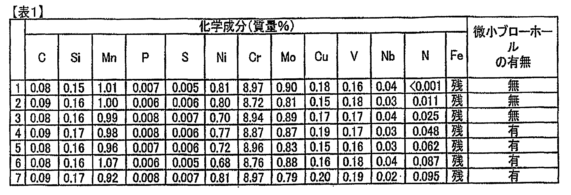
そこで、窒素含有量が異なり他の成分の含量は略同じである9%Cr系溶加材を試料1~7の7種類試作し、高Cr鋼と2.25CrMoV鋼からなる溶接継手の溶接を行い、超音波探傷試験により溶接金属内における微小ブローホールの発生状況を調べた。結果を表1にまとめる。表1において数値は試料中の各成分の含量(質量%)を表す。表1から明らかであるように、溶加材中の窒素含量が質量%で0.025%以下であるとき微小ブローホールは発生しなかった。従って、窒素含量が質量%で0.025%以下である9%Cr系溶加材を用いると、ブローホールの発生を防止できることが確認できた。
以下、図面を参照して本発明の好適な実施例を例示的に詳しく説明する。但しこの実施例に記載されている構成部品の寸法、材質、形状、その相対的配置等は特に特定的な記載がない限りは、この発明の範囲をそれに限定する趣旨ではなく、単なる説明例に過ぎない。
(タービンロータの製造)
図1は本発明により製造されたタービンロータの断面図であり、図2は図1における溶接部8近傍の拡大図である。図1に示すように高Cr鋼である10%Cr鋼又はWを含有する10%Cr鋼材からなる高温用ロータ材4と、低Cr鋼である2.25%CrMoV鋼又は3.5NiCrMoV鋼からなる低温用ロータ材6とを突き合わせ、窒素含有量が質量%で0.025%以下である9%Cr系溶加材を用いて例えばアーク溶接することにより、高温用ロータ材4と低温用ロータ材6との間に溶接部10を形成する。
前記高温用ロータ材4に用いられる10%Cr鋼又はWを含有する10%Cr鋼材、低温用ロータ材6に用いられる2.25%CrMoV鋼又は3.5NiCrMoV鋼、及び9%Cr系溶加材として、例えば表2に示す組成範囲が挙げられ、本実施例においては同じく表2に示した実施例の組成の材料を用いた。
前記低温用ロータ材6が2.25CrMoV鋼である場合、625~650℃の温度範囲で40~60時間熱処理を実施することで、高温用ロータ材をヴィッカース硬さでHV350以下にする。特に、高温用ロータ材が10%Cr鋼又はWを含有する10%Cr鋼である場合には、HV硬さを350以下とするためには熱処理時間を長時間保持することが好ましく、60時間とすることが特に好ましい。
図8はヴィッカース硬さと遅れ割れ発生領域を示すグラフである(ターボ機械協会 53回セミナー資料(2001年)「蒸気タービンの腐食とエロージョンについて」伊東眸)。図8から明らかであるように、ヴィッカース硬さHVが350以下であれば高温用ロータ部材にかかる応力が高くても遅れ割れは発生せず、ヴィッカース硬さHVが350を超えるとかかる応力が低くても遅れ割れが発生する。従って前記625~650℃の温度範囲で40~60時間熱処理を実施してヴィッカース硬さHVを350以下とすることで、遅れ割れを生じさせないタービンロータを製造することができる。
また、前記低温用ロータ材6が3.5NiCrMoV鋼である場合、595~620℃の温度範囲で40~60時間熱処理を実施することで、高温用ロータ材をヴィッカース硬さでHV350以下にすることができる。
(評価)
図3に示すように、前記表2に示す実施例の組成の高温用ロータ材4と低温用ロータ材6とをそれぞれ切削により開先加工した後、表1に示す9%Cr系溶加材を用いてこれらの部材4、6間に溶接部10を形成した。続いて溶接部10により形成された前記ロータ材4、6を前述の温度及び時間で熱処理を施して溶接継手を製造した。
前記溶接継手について図3に示すように厚さの1/2の箇所から試験片12を採取し、試験温度一定の元でクリープ試験を実施した。クリープ試験は、以下の2種類の溶接継手を製造して行った。
試験片1、高温用ロータ材:10%Cr鋼、低温用ロータ材:2.25%CrMoV鋼
試験片2、高温用ロータ材:W含有10%Cr鋼、低温用ロータ材:2.25%CrMoV鋼
また比較例として、試験片3、高温用ロータ材:10%Cr鋼、低温用ロータ材:1%CrMoV鋼の試験片を作成し、これについても試験温度一定の元でクリープ試験を行った。
結果を図5に示す。図5において縦軸は応力、横軸はクリープ試験温度と破断時間に応じて決まる値であり、試験温度一定の元でクリープ試験を行っているので、図5においては破断時間の指標となる値である。図5に示したように、本実施例においては、低温用ロータ材に1%CrMoV鋼を用いた比較例よりもクリープ強度の向上が成されていることが確認できた。
さらに前記試験片1、2について硬さ分布を測定した。結果を図6に示す。図6において縦軸はヴィッカース硬さHV、横軸は低温用ロータ材6の定点からの距離を示している。図6から明らかであるように、得られた溶接継手は10%Cr鋼又はWを含有する10%Cr鋼、その熱影響部、溶接部、2.25%CrMoV鋼、その熱影響部何れの箇所においてもHV350以下を示していることが確認できた。
さらに、以下の試験片4についても前記試験片1、2と同様に硬さ分布を測定した。
試験片4、高温用ロータ材:10%Cr鋼、低温用ロータ材:3.5%NiCrMoV鋼
結果を図7に示す。試験片4においても、試験片1、2と同様に何れの箇所においてもHV350以下を示していることが確認できた。
また、前記試験片1、2、4について、0.2%耐力、引張強さを測定した。その結果を表3に示す。さらにその熱影響部、溶接部の衝撃特性(室温における吸収エネルギー及び50%破面遷移温度)を調べた。その結果を表4に示す。なお、表3及び表4中における仕様値とは、製造されたタービンロータが問題なく使用されるために満足する必要のある範囲を表している。
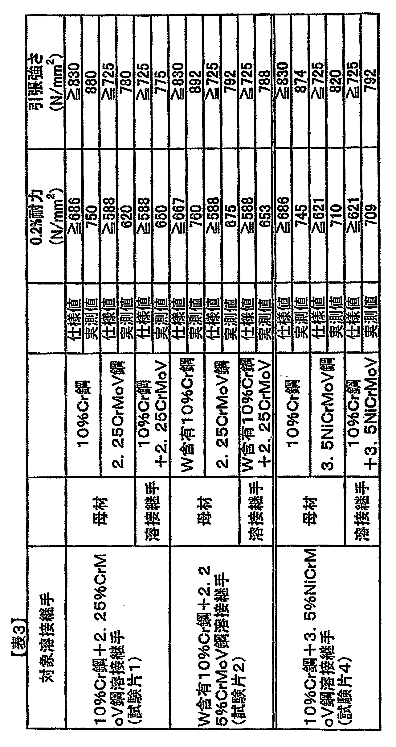
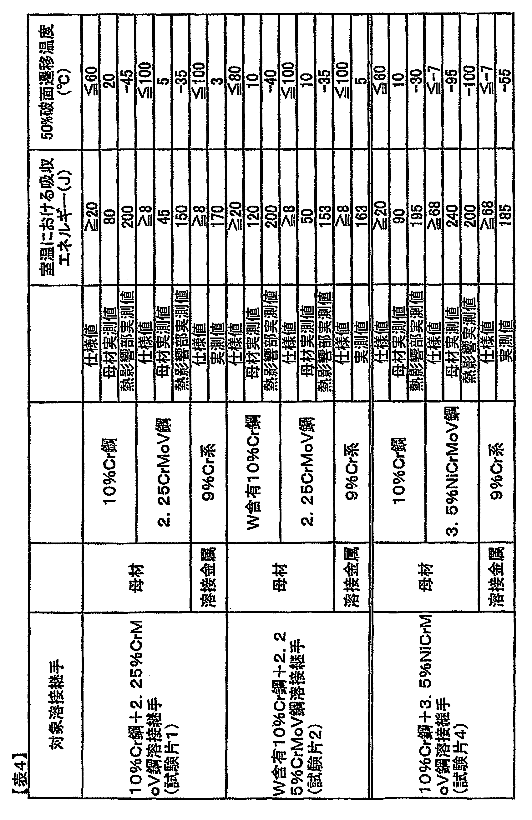
表3から明らかなように得られた溶接継手及びその構成母材の0.2%耐力及び引張強さの実測値は全て仕様値を満たしており、ロータに必要な強度レベルを満足していることがわかる。また、表4から明らかなように得られた溶接継手の母材、溶接部等は仕様値を十分満足する衝撃特性を有することがわかる。
以上のことから、本発明によって得られたタービンロータは溶接及び熱処理が1度であるため製造コストの高騰、製造時間の長期化を生じることなく、適正強度、靭性を有しているといえる。
Claims (6)
- 高Cr鋼からなる高温用ロータ材と、低Cr鋼からなる低温用ロータ材とを溶接して構成されたタービンロータにおいて、
前記高温用ロータ材が、窒素含有量が質量%で0.02%以上である高Cr鋼で形成され、
前記高温用ロータ材と低温用ロータ材を溶接する溶加材が、窒素含有量が質量%で0.025%以下である9%Cr系溶加材であることを特徴とするタービンロータ。 - 前記低温用ロータ材が、2.25CrMoV鋼で形成され、
溶接された前記高温用ロータ材と低温用ロータ材に対して、625~650℃で40~60時間熱処理して、前記高温用ロータ材のヴィッカース硬さをHV350以下としたことを特徴とする請求項1記載のタービンロータ。 - 前記低温用ロータ材が、3.5NiCrMoV鋼で形成され、
溶接された前記高温用ロータ材と低温用ロータ材に対して、595~620℃で40~60時間熱処理して、前記高温用ロータ材のヴィッカース硬さをHV350以下としたことを特徴とする請求項1記載のタービンロータ。 - 高Cr鋼からなる高温用ロータ材と、低Cr鋼からなる低温用ロータ材とを溶接して接合するタービンロータの製造方法において、
前記高温用ロータ材を、窒素含有量が質量%で0.02%以上である高Cr鋼で形成し、
前記高温用ロータ材と低温用ロータ材を、窒素含有量が質量%で0.025%以下である9%Cr系溶加材で溶接により接合することを特徴とするタービンロータの製造方法。 - 前記低温用ロータ材を2.25CrMoV鋼で形成し、
前記高温用ロータ材と低温用ロータ材とを溶接により接合した後、
溶接された前記高温用ロータ材と低温用ロータ材とを、625~650℃で40~60時間熱処理して、前記高温用ロータ材のヴィッカース硬さをHV350以下とすることを特徴とする請求項4記載のタービンロータの製造方法。 - 前記低温用ロータ材を3.5NiCrMoV鋼で形成し、
前記高温用ロータ材と低温用ロータ材とを溶接により接合した後、
溶接された前記高温用ロータ材と低温用ロータ材とを、595~620℃で40~60時間熱処理して、前記高温用ロータ材のヴィッカース硬さをHV350以下とすることを特徴とする請求項4記載のタービンロータの製造方法。
Priority Applications (4)
| Application Number | Priority Date | Filing Date | Title |
|---|---|---|---|
| CN200980100075.4A CN101790595B (zh) | 2008-10-08 | 2009-07-15 | 涡轮转子及涡轮转子的制造方法 |
| EP09806067.6A EP2206798B1 (en) | 2008-10-08 | 2009-07-15 | Process for production of turbine rotor |
| KR1020107002530A KR101141828B1 (ko) | 2008-10-08 | 2009-07-15 | 터빈 로터 및 터빈 로터의 제조 방법 |
| US12/673,387 US9109449B2 (en) | 2008-10-08 | 2009-07-15 | Turbine rotor and manufacturing method of turbine rotor |
Applications Claiming Priority (2)
| Application Number | Priority Date | Filing Date | Title |
|---|---|---|---|
| JP2008261660A JP4288304B1 (ja) | 2008-10-08 | 2008-10-08 | タービンロータ及びタービンロータの製造方法 |
| JP2008-261660 | 2008-10-08 |
Publications (1)
| Publication Number | Publication Date |
|---|---|
| WO2010041506A1 true WO2010041506A1 (ja) | 2010-04-15 |
Family
ID=40921818
Family Applications (1)
| Application Number | Title | Priority Date | Filing Date |
|---|---|---|---|
| PCT/JP2009/063137 Ceased WO2010041506A1 (ja) | 2008-10-08 | 2009-07-15 | タービンロータ及びタービンロータの製造方法 |
Country Status (6)
| Country | Link |
|---|---|
| US (1) | US9109449B2 (ja) |
| EP (1) | EP2206798B1 (ja) |
| JP (1) | JP4288304B1 (ja) |
| KR (1) | KR101141828B1 (ja) |
| CN (1) | CN101790595B (ja) |
| WO (1) | WO2010041506A1 (ja) |
Cited By (1)
| Publication number | Priority date | Publication date | Assignee | Title |
|---|---|---|---|---|
| WO2016056654A1 (ja) * | 2014-10-10 | 2016-04-14 | 三菱日立パワーシステムズ株式会社 | 軸体の製造方法 |
Families Citing this family (17)
| Publication number | Priority date | Publication date | Assignee | Title |
|---|---|---|---|---|
| JP5618701B2 (ja) * | 2010-08-24 | 2014-11-05 | 株式会社東芝 | 蒸気タービンのタービンロータおよび蒸気タービン |
| US8944761B2 (en) | 2011-01-21 | 2015-02-03 | General Electric Company | Welded rotor, a steam turbine having a welded rotor and a method for producing a welded rotor |
| JP5822496B2 (ja) * | 2011-03-23 | 2015-11-24 | 三菱日立パワーシステムズ株式会社 | タービンロータ及びタービンロータの製造方法 |
| JP2012207594A (ja) * | 2011-03-30 | 2012-10-25 | Mitsubishi Heavy Ind Ltd | 回転機械のロータ及び回転機械 |
| US9039365B2 (en) * | 2012-01-06 | 2015-05-26 | General Electric Company | Rotor, a steam turbine and a method for producing a rotor |
| CN102615394A (zh) * | 2012-04-23 | 2012-08-01 | 杭州泽军机电有限公司 | 一种铬钼钒钢的焊接方法 |
| EP2837769B1 (en) * | 2013-08-13 | 2016-06-29 | Alstom Technology Ltd | Rotor shaft for a turbomachine |
| US9821410B2 (en) | 2014-09-16 | 2017-11-21 | Honeywell International Inc. | Turbocharger shaft and wheel assembly |
| US9827631B2 (en) | 2014-09-16 | 2017-11-28 | Honeywell International Inc. | Turbocharger shaft and wheel assembly |
| US10041351B2 (en) | 2014-09-16 | 2018-08-07 | Honeywell International Inc. | Turbocharger shaft and wheel assembly |
| US10024166B2 (en) * | 2014-09-16 | 2018-07-17 | Honeywell International Inc. | Turbocharger shaft and wheel assembly |
| CN108080774A (zh) * | 2016-11-22 | 2018-05-29 | 上海电气电站设备有限公司 | 一种耐热钢在630度汽轮机转子中的应用及转子焊接方法 |
| CN106736300B (zh) * | 2017-01-10 | 2019-01-25 | 上海电气电站设备有限公司 | 由异种材料构成的涡轮转子的制造方法 |
| JP2019105250A (ja) * | 2017-12-14 | 2019-06-27 | 株式会社東芝 | タービンロータおよびタービンロータの製造方法 |
| JP7315454B2 (ja) * | 2019-12-25 | 2023-07-26 | 三菱重工業株式会社 | タービンロータ材料 |
| CN112621042B (zh) * | 2021-01-11 | 2022-11-04 | 东方电气集团东方锅炉股份有限公司 | 2.25Cr1Mo0.25V钢+碳锰低合金钢的异种钢焊接接头制造方法 |
| CN120480539A (zh) * | 2025-06-09 | 2025-08-15 | 哈尔滨汽轮机厂有限责任公司 | 采用高Cr钢-CrMoV合金钢电渣复合冶炼整体钢锭制造进汽温度620℃等级中压转子的方法 |
Citations (3)
| Publication number | Priority date | Publication date | Assignee | Title |
|---|---|---|---|---|
| JP2001123801A (ja) * | 1999-10-22 | 2001-05-08 | Mitsubishi Heavy Ind Ltd | タービン用ロータ及びその製造方法 |
| JP2003049223A (ja) * | 2001-08-03 | 2003-02-21 | Mitsubishi Heavy Ind Ltd | タービン用ロータの製造方法 |
| JP2008093668A (ja) * | 2006-10-06 | 2008-04-24 | Hitachi Ltd | 蒸気タービン溶接ロータ |
Family Cites Families (9)
| Publication number | Priority date | Publication date | Assignee | Title |
|---|---|---|---|---|
| JPS5982189A (ja) | 1982-11-02 | 1984-05-12 | Kobe Steel Ltd | Cr−Mo系低合金鋼用潜弧溶液用溶接ワイヤ |
| ATE49240T1 (de) * | 1985-07-09 | 1990-01-15 | Mitsubishi Heavy Ind Ltd | Hochtemperaturrotor fuer eine dampfturbine und verfahren zu seiner herstellung. |
| US4897519A (en) * | 1988-03-14 | 1990-01-30 | Westinghouse Electric Co. | More creep resistant turbine rotor, and procedures for repear welding of low alloy ferrous turbine components |
| JP3315800B2 (ja) * | 1994-02-22 | 2002-08-19 | 株式会社日立製作所 | 蒸気タービン発電プラント及び蒸気タービン |
| JP3009658B2 (ja) * | 1998-01-20 | 2000-02-14 | 三菱重工業株式会社 | 高Cr鋼材用溶接材料 |
| JP3999402B2 (ja) * | 1998-06-09 | 2007-10-31 | 三菱重工業株式会社 | 蒸気タービンの異材溶接ロータ |
| JP3854440B2 (ja) * | 2000-02-07 | 2006-12-06 | 三菱重工業株式会社 | 溶接材料およびガスメタルアーク溶接方法並びに溶接構造物 |
| JP2003049923A (ja) | 2001-08-07 | 2003-02-21 | Ebara Corp | 流体伝動装置 |
| JP4908137B2 (ja) * | 2006-10-04 | 2012-04-04 | 株式会社東芝 | タービンロータおよび蒸気タービン |
-
2008
- 2008-10-08 JP JP2008261660A patent/JP4288304B1/ja active Active
-
2009
- 2009-07-15 KR KR1020107002530A patent/KR101141828B1/ko active Active
- 2009-07-15 WO PCT/JP2009/063137 patent/WO2010041506A1/ja not_active Ceased
- 2009-07-15 CN CN200980100075.4A patent/CN101790595B/zh active Active
- 2009-07-15 EP EP09806067.6A patent/EP2206798B1/en active Active
- 2009-07-15 US US12/673,387 patent/US9109449B2/en active Active
Patent Citations (3)
| Publication number | Priority date | Publication date | Assignee | Title |
|---|---|---|---|---|
| JP2001123801A (ja) * | 1999-10-22 | 2001-05-08 | Mitsubishi Heavy Ind Ltd | タービン用ロータ及びその製造方法 |
| JP2003049223A (ja) * | 2001-08-03 | 2003-02-21 | Mitsubishi Heavy Ind Ltd | タービン用ロータの製造方法 |
| JP2008093668A (ja) * | 2006-10-06 | 2008-04-24 | Hitachi Ltd | 蒸気タービン溶接ロータ |
Non-Patent Citations (1)
| Title |
|---|
| See also references of EP2206798A4 * |
Cited By (2)
| Publication number | Priority date | Publication date | Assignee | Title |
|---|---|---|---|---|
| WO2016056654A1 (ja) * | 2014-10-10 | 2016-04-14 | 三菱日立パワーシステムズ株式会社 | 軸体の製造方法 |
| US10590508B2 (en) | 2014-10-10 | 2020-03-17 | Mitsubishi Hitachi Power Systems, Ltd. | Method for manufacturing shaft body |
Also Published As
| Publication number | Publication date |
|---|---|
| KR101141828B1 (ko) | 2012-05-07 |
| US20110206525A1 (en) | 2011-08-25 |
| CN101790595B (zh) | 2011-09-21 |
| EP2206798A4 (en) | 2015-02-18 |
| JP4288304B1 (ja) | 2009-07-01 |
| EP2206798A1 (en) | 2010-07-14 |
| CN101790595A (zh) | 2010-07-28 |
| KR20100074104A (ko) | 2010-07-01 |
| EP2206798B1 (en) | 2017-02-15 |
| US9109449B2 (en) | 2015-08-18 |
| JP2010090805A (ja) | 2010-04-22 |
Similar Documents
| Publication | Publication Date | Title |
|---|---|---|
| JP4288304B1 (ja) | タービンロータ及びタービンロータの製造方法 | |
| Sharma et al. | A-TIG welding of dissimilar P92 steel and 304H austenitic stainless steel: Mechanisms, microstructure and mechanical properties | |
| US9873930B2 (en) | Precipitation hardening martensitic stainless steel and steam turbine component made thereof | |
| WO2011158706A1 (ja) | Ni基耐熱合金用溶接材料ならびにそれを用いてなる溶接金属および溶接継手 | |
| Zhu et al. | Effects of temperature on tensile and impact behavior of dissimilar welds of rotor steels | |
| CN102310292A (zh) | 用于合金钢的异种焊接的设备和方法 | |
| WO2013065521A1 (ja) | Ni基耐熱合金用溶接材料ならびにそれを用いてなる溶接金属および溶接継手 | |
| Handa et al. | Investigation of mechanical properties of friction-welded AISI 304 with AISI 1021 dissimilar steels | |
| Wu et al. | Rupture behavior and fracture mode for Inconel 625–9% Cr steel dissimilar welded joints at high temperature | |
| JP5011931B2 (ja) | 蒸気タービン溶接ロータ | |
| US9346132B2 (en) | Metal chemistry for improved weldability of super alloys | |
| Falat et al. | Ageing Effects on Microstructure, Mechanical Properties, and Fracture Behaviour of 9Cr‐1.5 Mo‐1Co‐VNbBN Martensitic Steel Welded Joint for High Temperature Application | |
| JP2006075853A (ja) | オーステナイト系合金鋼のレーザ溶接継手およびその製造方法 | |
| JP6189737B2 (ja) | 蒸気タービン低圧ロータ及びその製造方法 | |
| Kumar et al. | The Behavior of Dissimilar Welded Joint of Alloy 617/P92 Steel at High Temperatures | |
| KR101974012B1 (ko) | 스테인리스강과 탄소강의 이종금속 용접방법 및 이를 통해 용접된 용접부 | |
| Tahaei et al. | Gas Tungsten Arc Welding Joints: Impact of Post Weld Heat Treatment (PWHT) and Nitrogen Addition in Shielding Gas | |
| JP4283380B2 (ja) | 異種材料溶接型タービンロータ及びその製造方法 | |
| JP4702267B2 (ja) | 析出硬化型マルテンサイト系ステンレス鋼 | |
| JP2014176877A (ja) | 異材継手 | |
| de Oliveira et al. | Effect of welding parameters on the microstructure and mechanical behavior of dissimilar AISI 304/AISI 430 thin plates welded by gas Tungsten arc welding | |
| Sufizadeh et al. | Metallurgical and mechanical research on dissimilar electron beam welding of AISI 316L and AISI 4340 | |
| Kasl et al. | Behaviour of dissimilar weld joint of steels FB2 and F during long-term creep test | |
| EP2564978B1 (en) | Filler metal chemistry for improved weldability of super alloys | |
| ES3013062T3 (en) | High gamma prime nickel based welding material |
Legal Events
| Date | Code | Title | Description |
|---|---|---|---|
| WWE | Wipo information: entry into national phase |
Ref document number: 200980100075.4 Country of ref document: CN |
|
| ENP | Entry into the national phase |
Ref document number: 20107002530 Country of ref document: KR Kind code of ref document: A |
|
| WWE | Wipo information: entry into national phase |
Ref document number: 12673387 Country of ref document: US |
|
| REEP | Request for entry into the european phase |
Ref document number: 2009806067 Country of ref document: EP |
|
| WWE | Wipo information: entry into national phase |
Ref document number: 2009806067 Country of ref document: EP |
|
| 121 | Ep: the epo has been informed by wipo that ep was designated in this application |
Ref document number: 09806067 Country of ref document: EP Kind code of ref document: A1 |
|
| NENP | Non-entry into the national phase |
Ref country code: DE |