WO2010044139A1 - タービン動翼の欠陥検出装置及びタービン動翼の欠陥検出方法 - Google Patents
タービン動翼の欠陥検出装置及びタービン動翼の欠陥検出方法 Download PDFInfo
- Publication number
- WO2010044139A1 WO2010044139A1 PCT/JP2008/068587 JP2008068587W WO2010044139A1 WO 2010044139 A1 WO2010044139 A1 WO 2010044139A1 JP 2008068587 W JP2008068587 W JP 2008068587W WO 2010044139 A1 WO2010044139 A1 WO 2010044139A1
- Authority
- WO
- WIPO (PCT)
- Prior art keywords
- blade
- turbine
- eddy current
- current probe
- rotor
- Prior art date
- Legal status (The legal status is an assumption and is not a legal conclusion. Google has not performed a legal analysis and makes no representation as to the accuracy of the status listed.)
- Ceased
Links
Images


Classifications
-
- G—PHYSICS
- G01—MEASURING; TESTING
- G01N—INVESTIGATING OR ANALYSING MATERIALS BY DETERMINING THEIR CHEMICAL OR PHYSICAL PROPERTIES
- G01N27/00—Investigating or analysing materials by the use of electric, electrochemical, or magnetic means
- G01N27/72—Investigating or analysing materials by the use of electric, electrochemical, or magnetic means by investigating magnetic variables
- G01N27/82—Investigating or analysing materials by the use of electric, electrochemical, or magnetic means by investigating magnetic variables for investigating the presence of flaws
- G01N27/90—Investigating or analysing materials by the use of electric, electrochemical, or magnetic means by investigating magnetic variables for investigating the presence of flaws using eddy currents
- G01N27/9006—Details, e.g. in the structure or functioning of sensors
-
- G—PHYSICS
- G01—MEASURING; TESTING
- G01N—INVESTIGATING OR ANALYSING MATERIALS BY DETERMINING THEIR CHEMICAL OR PHYSICAL PROPERTIES
- G01N27/00—Investigating or analysing materials by the use of electric, electrochemical, or magnetic means
- G01N27/72—Investigating or analysing materials by the use of electric, electrochemical, or magnetic means by investigating magnetic variables
- G01N27/82—Investigating or analysing materials by the use of electric, electrochemical, or magnetic means by investigating magnetic variables for investigating the presence of flaws
- G01N27/90—Investigating or analysing materials by the use of electric, electrochemical, or magnetic means by investigating magnetic variables for investigating the presence of flaws using eddy currents
-
- G—PHYSICS
- G01—MEASURING; TESTING
- G01N—INVESTIGATING OR ANALYSING MATERIALS BY DETERMINING THEIR CHEMICAL OR PHYSICAL PROPERTIES
- G01N27/00—Investigating or analysing materials by the use of electric, electrochemical, or magnetic means
- G01N27/72—Investigating or analysing materials by the use of electric, electrochemical, or magnetic means by investigating magnetic variables
- G01N27/82—Investigating or analysing materials by the use of electric, electrochemical, or magnetic means by investigating magnetic variables for investigating the presence of flaws
- G01N27/90—Investigating or analysing materials by the use of electric, electrochemical, or magnetic means by investigating magnetic variables for investigating the presence of flaws using eddy currents
- G01N27/9013—Arrangements for scanning
- G01N27/902—Arrangements for scanning by moving the sensors
Definitions
- the present invention relates to a defect inspection technique for a turbine rotor blade of a steam turbine, and more particularly to a turbine rotor blade defect detection device and a turbine rotor blade defect detection method for detecting a defect occurring in an implanted portion of a turbine rotor blade.
- an ultrasonic probe is installed on a turbine blade having a structure in which a turbine blade is attached to a turbine rotor, and an ultrasonic inspection is performed on the attachment portion of the turbine blade with the ultrasonic probe, If no defects are detected by this ultrasonic inspection, a part of the turbine blades are extracted from the turbine rotor, and a magnetic particle inspection method or a penetrating inspection method with a defect detection limit smaller than that of the ultrasonic inspection method is performed.
- a technique for detecting a defect at an attachment site is disclosed.
- vibration of a turbine blade attached to a wheel of a turbine rotor is detected by a strain detector provided on the turbine blade, and a vibration signal of the turbine blade detected by the strain detector is detected.
- Technology to accurately measure the vibration of turbine rotor blades by FM conversion from a transmitter provided on the wheel of the turbine rotor and transmission by a receiver provided on a stationary body of the turbine opposite to this transmitter Is disclosed.
- Japanese Patent Application Laid-Open No. 7-280773 discloses a technique for attaching an eddy current sensor to a torque tube housing of a combustion turbine engine by support / positioning means and detecting cracks on the surface of an air separator, which is a rotating member, using this eddy current sensor. ing.
- JP 2003-294716 A Japanese Utility Model Publication No.59-98325 JP 7-280773 A
- the eddy current sensor is installed at a large distance from the turbine blade implantation portion in order to avoid contact with the turbine blade implantation portion, defects such as cracks generated in the turbine blade implantation portion will be accurately detected. There is a problem that it cannot be detected.
- An object of the present invention is to accurately detect a defect generated in an implanted portion of a turbine rotor blade even when the turbine rotor blade vibrates in the rotor axial direction as the rotor rotates, and to take a great amount of time and labor. It is an object of the present invention to provide a turbine blade defect detection device and a turbine blade defect detection method capable of inspecting a defect generated in a blade implantation portion of a turbine blade to be inspected without performing an opening operation. .
- a turbine rotor blade defect detection apparatus includes a turbine rotor rotatably installed inside a turbine casing, and a plurality of turbine rotor blades arranged in an annular shape on the outer periphery of the turbine rotor, The rotor groove formed in the rotor disk portion of the rotor and the blade groove formed in the root portion of the turbine rotor blade are fitted together to form an implanted portion of the turbine rotor blade, and a plurality of static blades adjacent to the turbine rotor blade are formed.
- An indentation is provided on the side of the web of the stationary blade diaphragm facing the section, and an eddy current probe that detects the state of the implanted part of the turbine blade is moved in this indentation
- a rod having a signal line for transmitting a detection signal detected by the eddy current probe is connected to the eddy current probe, and a hole formed in the turbine casing and a stationary blade blade of a stationary blade diaphragm are formed.
- the present invention is characterized in that a data analysis device is provided for determining the state of a defect generated in the implanted portion of the turbine rotor blade based on the detection signal of the implanted portion of the blade.
- the turbine rotor blade defect detection apparatus of the present invention includes a turbine rotor rotatably installed inside a turbine casing, and a plurality of turbine rotor blades arranged in an annular shape on the outer periphery of the turbine rotor, A rotor groove formed in a rotor disk portion of a turbine rotor and a blade groove formed in a root portion of the turbine rotor blade are fitted to form an implanted portion of the turbine rotor blade.
- An eddy current probe for detecting the state of the implanted portion of the turbine blade is installed, and the stationary blade diaphragm is placed on the side surface of the stationary blade diaphragm facing the implanted portion of the turbine rotor blade.
- Another tapered surface corresponding to the tapered surface formed on the bottom surface of the groove portion is formed on the stationary blade diaphragm side of the probe, and the eddy current probe is inserted into the turbine rotor blade implantation portion by sliding of both the tapered surfaces.
- An analysis apparatus is provided.
- a blade groove formed at the root of a plurality of turbine blades arranged annularly on the outer periphery of a turbine rotor rotatably installed inside a turbine casing is An inner peripheral side of a stationary blade diaphragm in which a plurality of stationary blades are arranged in an annular shape in a turbine rotor blade defect detection method that is fitted with a rotor groove formed in a rotor disk portion of a rotor to constitute an implanted portion of a turbine blade.
- Eddy current probe is movably disposed in a recess formed on the side surface of the web facing the implanted portion of the turbine blade, and a defect in the implanted portion of the turbine blade
- a rod having a signal line connected to the eddy current probe and transmitting a detection signal detected by the eddy current probe is connected to the turbine case.
- the eddy current probe connected to the moving rod is moved with respect to the implanted part of the turbine rotor blade by moving it from the outside of the turbine casing and moving through the hole formed in the turbine casing and the air gap formed in the stator blade of the stator blade diaphragm.
- the turbine blade defect detection method of the present invention is a blade groove formed at the root of a plurality of turbine blades arranged in an annular shape on the outer periphery of a turbine rotor rotatably installed inside the turbine casing.
- An inner periphery of a stationary blade diaphragm in which a plurality of stationary blades are arranged in an annular shape in a turbine rotor blade defect detection method that is fitted with a rotor groove formed in a rotor disk portion of a turbine rotor and constitutes an implanted portion of a turbine blade.
- An eddy current probe is detachably disposed in a groove portion opened in the radial direction of the stationary blade diaphragm on the side surface of the web facing the implanted portion of the turbine rotor blade.
- a rod having a signal line that is connected to the eddy current probe and transmits a detection signal detected by the eddy current probe when detecting the state of the wing implantation portion The space between the hole formed in the turbine casing by inserting from the outside of the turbine casing and the stationary blade blade installed in the stationary blade diaphragm is moved, and the eddy current probe connected to the moving rod is moved to the stationary blade diaphragm.
- the eddy current transmitted through the rod is inserted into a groove formed in the side surface of the web of the web and is brought close to the implanted portion of the turbine blade to detect the state of the implanted portion of the turbine blade by the eddy current probe.
- the present invention is characterized in that the state of a defect generated in the implanted portion of the turbine rotor blade is determined based on a detection signal of the state of the implanted portion of the turbine blade detected by the probe.
- the present invention even when the turbine blades vibrate in the rotor axial direction as the rotor rotates, it is possible to accurately detect defects generated in the implanted portions of the turbine blades and to take a great amount of work and time.
- a turbine rotor blade defect detection device and a turbine rotor blade defect detection method capable of inspecting defects generated in the rotor blade implantation portion of the turbine rotor blade to be inspected without performing the opening operation.
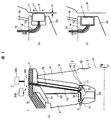
- FIG. 1 is a structural diagram showing an eddy current probe constituting a turbine rotor blade defect detection device according to a first embodiment of the present invention, and a partial cross-sectional view of a steam turbine showing a steam turbine provided with a turbine rotor blade defect detection device.
- FIG. 1 is a perspective view showing an eddy current probe constituting a defect detecting device for a turbine rotor blade according to the first embodiment of the present invention shown in FIG. 1, and a stationary blade diaphragm provided with the defect detecting device for a turbine rotor blade is installed in a turbine rotor.
- FIG. 1 The perspective view of the turbine blade which shows the moving blade implantation part of the turbine moving blade used as the test object by the defect detection apparatus of the turbine moving blade which is 1st Example of this invention, and the part which expands and shows the moving blade implantation part Figure.
- the flowchart which showed the procedure of the test
- Schematic shows an example of the slit formed in the moving blade implantation part of the turbine moving blade used for calibration of the eddy current probe of the defect detection apparatus which is an Example of a turbine moving blade.
- FIG. 6 is a structural diagram showing an eddy current probe constituting a turbine rotor blade defect detection apparatus according to a second embodiment of the present invention.
- FIG. 9 is a structural diagram showing an eddy current probe constituting a turbine rotor blade defect detection device according to a third embodiment of the present invention.
- FIG. 6 is a structural diagram showing an eddy current probe constituting a turbine rotor blade defect detection device according to a fourth embodiment of the present invention.
- FIG. 6 is a structural diagram showing an eddy current probe constituting a defect detection device for a turbine rotor blade according to a fifth embodiment of the present invention, and a partial cross-sectional view of the steam turbine showing a steam turbine provided with the defect detection device for a turbine rotor blade.
- FIGS. 1-10 A turbine blade defect detection apparatus and a turbine blade defect detection method according to a first embodiment of the present invention will be described with reference to FIGS.
- FIG. 1A is a partial cross-sectional view of a steam turbine showing a steam turbine in which a turbine rotor blade defect detection apparatus according to a first embodiment of the present invention is installed.
- a steam turbine 1 includes a plurality of turbine motions having a turbine rotor 3 and moving blade blades 41 arranged annularly on the outer periphery of the turbine rotor 3 inside a turbine casing 2 that covers the outer periphery of the turbine.
- the blade 4 and the stationary blade diaphragm 5 having a plurality of stationary blade blades 52 arranged in an annular manner are disposed adjacent to the upstream side of the plurality of turbine blades 4 arranged in an annular shape.
- FIG. 1 (a) only one stage of the turbine stage composed of the stationary blades 52 and the turbine blades 4 is shown for convenience of explanation, but there are a plurality of turbine stages along the axial direction of the turbine rotor 3. Paragraphs are arranged.
- the turbine rotor 3 includes a rotor shaft 31 that is a rotating shaft of the turbine, an annular rotor disk 32 attached to the outer periphery of the rotor shaft 31, and root portions of the plurality of turbine rotor blades 4 along the outer periphery of the rotor disk 32.
- the rotor blades 32 are formed on the outer periphery of the rotor disk 32 to be fitted with the blade grooves 42 formed at the root portion of the turbine rotor blade 4 (hereinafter referred to as directions).
- directions hereinafter referred to as directions.
- the description is expressed as an axial direction, a radial direction, and a circumferential direction with reference to the rotating shaft of the turbine).
- the turbine rotor blades 4 arranged in a ring shape on the rotor disk 32 are formed in the turbine rotor 3 and the rotor blades 41 that receive the high-pressure steam flow as the working fluid and convert the high-pressure steam flow into the rotational energy of the turbine. It consists of a blade groove 42 formed in the implanted portion of the turbine rotor blade 4 fitted to the rotor groove 33.
- the connecting portion where the rotor groove 33 formed in the rotor disk 32 and the blade groove 42 formed in the root portion of the turbine rotor blade 4 are fitted together is referred to as a rotor blade implantation portion 6 of the turbine rotor blade 4.
- the stationary blade diaphragms 5 are respectively disposed between the turbine rotor blades 4 that are installed apart from each other along the axial direction of the turbine rotor 3.
- the stationary blade diaphragm 5 is located adjacent to the ring 51 fixed to the turbine casing 2 on the outer peripheral side of the stationary blade diaphragm 5 and the upstream side or the downstream side of the moving blade blade 41 of the turbine moving blade 4.
- a plurality of stationary blade blades 52 arranged in an annular shape for regulating the flow of the steam that has passed through the blade blades 41, and the stationary blade diaphragm 5 adjacent to the blade insertion portion 6 and the rotor disk 32 of the turbine blade 4 in the roller axial direction.
- an annular web 53 disposed in the vicinity of the rotor shaft 31 on the inner peripheral side thereof, and these members are joined to each other by welding.
- a turbine rotor blade defect detection device 7 for detecting defects occurring in the blade implanting portion 6 is an annular web installed on the inner peripheral side of the stationary blade diaphragm 5 at a position facing the rotor blade implanting portion 6 of the turbine rotor blade 4.
- An eddy current probe 71 for detecting a defect generated in the moving blade implanting portion 6 of the turbine blade 4 moves along the rotor axial direction inside the recess 73 formed in the 53 and moves in the moving blade implanting portion 6 of the turbine blade 4. It is attached so that it can be separated from the surface.
- the turbine rotor blade defect detection device 7 is installed in a recess 73 formed in the web 53 of the stationary blade diaphragm 5 so as to face the rotor blade implantation portion 6 of the turbine rotor blade 4 as shown in FIG.
- An eddy current probe 71 that moves back and forth in the axial direction of the rotor and can be separated from and attached to the surface of the moving blade implanting portion 6 of the turbine blade 4, and one end of the eddy current probe 71 is connected to the stationary blade diaphragm.
- the web hole 74 provided at the bottom of the recess 73 formed in the web 53, the air gap 75 inside the stationary blade blade 52 provided in the stationary blade diaphragm 5, the ring 51, and the casing hole 76 formed in the turbine casing 2 are sequentially passed through.
- the moving blade implanting portion 6 of the turbine moving blade 4 measured by the eddy current probe 71 in a state where the turbine moving blade 4 is rotated at a low speed.
- a moving device 150 installed outside the turbine casing 2 that moves the fiber rod 72 back and forth, and the fiber rod 72.
- the data analysis device 300 is configured.
- the fiber rod 72 may be manually operated from the outside of the turbine casing 2 and moved back and forth. In this case, the moving device 150 that moves the fiber rod 72 and the control device 200 that drives the moving device 150. Is no longer necessary.
- the current probe 71 detects an electromagnetic induction change generated in the moving blade implanting section 6 by causing an eddy current to flow on the surface of the moving blade implanting section 6 of the turbine blade 4.
- the position and depth of a flaw generated in the moving blade implanting portion 6 is detected by performing arithmetic processing based on the change in electromagnetic induction detected in 71.
- a rotatable guide roller 77 is attached to the front surface of the eddy current probe 71, and the eddy current probe 71 is moved forward in the rotor axial direction by a forward / backward movement operation of the fiber rod 72 to move the turbine blade 4.
- the guide roller 77 provided on the front surface of the eddy current probe 71 functions as a guide that contacts the surface of the moving blade implanting portion 6 of the turbine moving blade 4 rotating around the rotor axis when the blade implanting portion 6 is inspected. Yes.
- the moving blade implanting section 6 of the turbine moving blade 4 is based on a detection signal of a change in electromagnetic induction generated in the moving blade implanting section 6 of the turbine moving blade 4 measured by the eddy current probe 71.
- the defect position such as scratches is analyzed and the position and depth of the defect are displayed.
- One eddy current probe 71 is installed on each side of the stationary blade diaphragm 5 in the axial direction facing the moving blade implantation portion 6 of the turbine moving blade 4 to be inspected.
- the eddy current probe 71 includes the moving blade implanting portion 6 of the turbine moving blade 4 positioned on the downstream side of the stationary blade diaphragm 5 and the moving blade implanting portion 6 of the turbine moving blade 4 positioned on the upstream side of the stationary blade diaphragm 5. (Not shown) are housed one by one in recesses 73 formed on both sides of the web 53 of the stationary blade diaphragm 5 in the axial direction so as to face each other.
- the detection signal of the change of the electromagnetic induction in the moving blade implanting portion 6 of the turbine moving blade 4 which detects the change of the electromagnetic induction generated in the moving blade implanting portion 6 by flowing the eddy current from each eddy current probe 71 is a stationary blade diaphragm. 5, a web hole 74 provided at the bottom of a recess 73 formed in the web 53, a void 75 inside the stationary blade blade 52 provided in the stationary blade diaphragm 5, a ring 51, and a casing hole 76 formed in the turbine casing 2.
- the eddy current probe 71 is placed in the recess 73 formed in the web 53 of the stationary blade diaphragm 5.
- a moving device 150 that moves the fiber rod 72 that moves back and forth in the rotor axial direction back and forth in the arrangement direction is installed outside the turbine casing 2. The driving of the moving device 150 is operated by an operation command from the control device 200.
- the moving device 150 installed outside the turbine casing 2 is driven to push the fiber rod 72 forward, and the eddy current probe 71 connected to the tip of the fiber rod 72 is inserted into the rotor from the opening surface of the recess 73. It is pushed forward in the axial direction and brought into contact with the surface of the moving blade implanting portion 6 of the turbine blade 4, and an eddy current is caused to flow from the eddy current probe 71 to the surface of the moving blade implanting portion 6 of the turbine blade 4.
- a defect state in the moving blade implanted portion 6 of the turbine moving blade 4 is inspected.
- a guide roller 77 is attached to the front surface of the eddy current probe 71, and the eddy current probe 71 is pushed forward in the rotor axial direction so that the surface of the moving blade implanting portion 6 of the turbine rotor blade 4 and the guide roller of the eddy current probe 71. 77, a desired gap d1 of 0.5 to 1.0 mm optimum for the eddy current probe 71 is formed between the surface of the eddy current probe 71 and the surface of the moving blade implanting portion 6. It is like that.
- the eddy current probe 71 has a structure in which a guide roller 77 provided on the front surface of the eddy current probe 71 comes into contact with the surface of the moving blade implanting portion 6 of the turbine moving blade 4 so that the moving blade implantation of the turbine moving blade 4 is performed by the rotation of the turbine rotor. Even when the portion 6 vibrates in the rotor axial direction, a desired gap d1 of 0.5 to 1.0 mm can always be maintained between the surface of the eddy current probe 71 and the surface of the moving blade implanting portion 6. Therefore, it is possible to accurately inspect whether or not a defect has occurred in the rotor blade implantation portion 6 of the turbine rotor blade 4 using the eddy current probe 71.
- the moving device 150 When the moving blade implantation portion 6 of the turbine moving blade 4 is not inspected, as shown in FIG. 1C, the moving device 150 is driven or the fiber rod 72 is pulled in by manual operation.
- the eddy current probe 71 connected to is largely separated from the surface of the rotor blade implanting portion 6 of the turbine rotor blade 4, and is retracted from the opening surface of the recess 73 toward the rear side in the rotor axial direction and stored in the recess 73.
- the fiber rod 72 has a flexible structure in which the portion corresponding to the L-shaped bent pipe of the web hole 74 is bendable, but the other portion is a rigid body, and is not driven and retracted by driving of the moving device 150 or manual operation. Thus, an appropriate pressing force and pulling force can be applied to the eddy current probe 71 without buckling.
- a cable (not shown) for transmitting a detection signal of a defect state of the moving blade implanting portion 6 of the turbine moving blade 4 detected by the eddy current probe 71 is incorporated.
- FIG. 2 (a) is a schematic structural view of the stationary blade diaphragm in which the turbine blade defect detecting device according to the first embodiment of the present invention shown in FIG. 1 is installed as seen from the axial direction of the turbine rotor.
- an eddy current probe 71 that constitutes a part of the turbine blade defect detection device is an inner portion of the stationary blade diaphragm 5 that faces the blade implantation portion 6 of the turbine blade 4 to be inspected.
- the webs 53 provided on the circumferential side are respectively provided in recesses 73 formed in one annular region on both sides in the axial direction.
- FIG. 2 (b) is a perspective view showing an eddy current probe constituting the defect detecting device for a turbine rotor blade according to the first embodiment of the present invention shown in FIG.
- a first coil element that causes an eddy current to flow on the surface of the moving blade implanted portion 6 of the turbine blade 4;
- Each coil element 78 configured to include a second coil element that detects a change in electromagnetic induction generated on the surface of the moving blade implanting portion 6 of the turbine blade 4 by flowing an eddy current includes 2 in the radial direction.
- the coil elements 78 are arranged in series.
- the coil elements 78 are arranged on the front surface of the eddy current probe 71 when the guide roller 77 on the front surface of the eddy current probe 71 comes into contact with the rotor blade implantation portion 6 to be inspected of the turbine blade 4. Between the coil element 78 of the turbine rotor blade 4 and the surface of the rotor blade implanting portion 6 of the turbine rotor blade 4 while maintaining a desired gap d1 of 0.5 to 1.0 mm. Range to be inspected in the radial direction It is disposed in front of the eddy current probe 71 over the length which can be a bar.
- Two rotatable guide rollers 77 installed on the front surface of the eddy current probe 71 are installed in parallel on both sides of the coil element 78, and an axle (not shown) held inside the eddy current probe 71. ) Is rotatably fixed.
- FIG. 2 (c) shows a state in which the guide roller 77 of the eddy current probe 71 is in contact with the surface of the moving blade implanting portion 6 of the turbine moving blade 4 to be inspected.
- the guide roller 77 on the front surface of the eddy current probe 71 in contact with the surface of the moving blade implanting portion 6 also moves around the axle. To ensure smooth sliding with the surface of the rotor blade implantation portion 6 of the turbine rotor blade 4.
- the gap between the coil element 78 installed on the front surface of the eddy current probe 71 and the moving blade implanting portion 6 of the turbine moving blade 4 to be inspected is necessary for detecting defects generated in the moving blade implanting portion 6. Since the gap d1 can always be maintained, the coil element 78 of the eddy current probe 71 can scan the surface of the moving blade implanting portion 6 of the turbine moving blade 4.
- FIG. 3 (a) is a perspective view of the turbine rotor blade showing a rotor blade implantation portion of the turbine rotor blade to be inspected by the turbine rotor blade defect detection apparatus according to the first embodiment of the present invention.
- FIG. 3 (a) a plurality of turbine rotor blades 4 are annularly arranged on an annular rotor disk 32 attached to the outer periphery of a rotor shaft 31 constituting the turbine rotor 3.
- the blade groove 42 formed in the root portion of the turbine rotor blade 4 in the rotor blade implanting portion 6 of the turbine rotor blade 4 is fitted with the rotor groove 33 formed on the outer periphery of the rotor disk 32, so that the turbine motion
- the blades 4 are connected to the rotor disk 32 of the turbine rotor 3.
- FIG. 3 (b) is an enlarged partial view showing the moving blade implantation portion of the turbine moving blade shown in FIG. 3 (a).
- the blade groove 42 formed at the base of the turbine blade 4 that becomes the blade embedded portion 6 of the turbine blade 4 has a zigzag groove shape having a plurality of inverted Christmas tree-shaped protrusions.
- the rotor groove 42 formed in the root portion of the turbine rotor blade 4 has a zigzag groove shape having a plurality of recesses formed in the rotor disk 32 and corresponding to the groove shape of the blade groove 42 of the turbine rotor blade 4.
- the grooves 33 and the grooves 33 are formed to form a strong fit and are connected to each other.
- the turbine blade 4 is subjected to radial centrifugal force and vibration loads in the rotor axial direction and circumferential direction.
- a large stress is locally generated by the load acting on the fitting structure of the moving blade implanting portion 6 of the turbine moving blade 4, and the risk that the crack 61 is generated. Becomes higher.
- the inspection target range of the moving blade implantation portion 6 of the turbine blade 4 is covered in the radial direction.
- the coil element 78 arranged over the length is installed on the front surface of the eddy current probe 71.
- an eddy current is caused to flow by the eddy current probe 71 of the defect detection device 7 over the entire annular region of the surface of the moving blade implanting portion 6 of the turbine moving blade 4 to be inspected indicated by a two-dot chain line in FIG.
- the eddy current probe 71 By detecting a change in electromagnetic induction generated on the surface of the moving blade implanting portion 6 of the turbine blade 4 by the eddy current probe 71, it is possible to inspect whether or not a defect has occurred.
- FIG. 3C shows a data analysis apparatus 300 based on a detection signal obtained by inspecting the rotor blade implantation part 6 of the turbine rotor blade 4 by the eddy current probe 71 provided in the turbine rotor blade defect inspection apparatus 7 of the first embodiment.
- FIG. 6 is an image diagram in which defects determined by arithmetic processing are displayed on the screen as inspection result output 8.
- the eddy current probe 71 described above reacts to a crack of a defect at a depth of several millimeters from the surface of the rotor blade implantation portion 6 of the turbine rotor blade 4, the eddy current probe 71 is measured by the data analysis apparatus 300.
- the turbine moving blade constituting the fitting structure of the moving blade implanting portion 6 of the turbine moving blade 4
- Indication 81 of the inspection result output 8 corresponding to the blade groove 42 formed at the root part of 4 and the rotor groove 33 formed on the rotor disk 32 is displayed on the screen.
- These blade groove 42 and rotor groove 33 are displayed on the screen. Since the groove has a fixed shape, it is possible to easily identify the indefinite shape indication 82 corresponding to the defect crack 61.
- FIG. 4 shows a defect for inspecting the defect of the moving blade implanting portion 6 of the turbine moving blade 4 provided in the steam turbine for thermal power generation using the turbine moving blade defect inspection apparatus 7 according to the first embodiment of the present invention. It is the flow which showed the procedure of inspection.
- the steam turbine is rotating at 3000 rpm or 3600 rpm, and the peripheral speed at which the moving blade implanting portion 6 of the turbine moving blade 4 to be inspected of the steam turbine rotates is as high as 100 m / s or higher. Therefore, it is impossible to detect a defect in the moving blade implanting portion 6 of the turbine moving blade 4 by using the eddy current probe 71 provided in the defect inspection apparatus 7.
- this defect inspection is carried out during one day when the steam turbine for thermal power generation ceases operation, or during the operation cessation period every several days.
- the defect inspection of the rotor blade implantation portion 6 of the turbine rotor blade 4 is performed according to the following procedure.
- step 101 the rated operation of the steam turbine is stopped.
- step 102 the moving device 150 is driven by the command signal of the control device 200 constituting the defect detecting device 7 of the turbine rotor blade 4 and the fiber rod 72 is pushed in from the outside of the turbine casing 2, so that FIG.
- the eddy current probe 71 is extruded from the opening surface of the recess 73 formed in the web 53 of the stationary blade diaphragm 5 to the front side in the rotor axial direction, and the coils arranged on the front surface of the eddy current probe 71 are arranged.
- Guide rollers 77 provided in parallel on both sides of the element 78 are brought into contact with the surface of the rotor blade implantation portion 6 of the turbine rotor blade 4.
- step 103 the rotor shaft 31 of the steam turbine 1 is rotated by an external power supply motor (not shown), and the low speed operation is performed in which the steam turbine 1 is rotated at a low speed.
- the rotor shaft 31 of the steam turbine 1 is rotated at a peripheral speed of the moving blade implanting portion 6 of the turbine moving blade 4 of 10 mm / s at which defects can be detected by the eddy current probe 71.
- step 104 the eddy current probe 71 is calibrated. This is because the eddy current is generated on the surface of the moving blade implanting portion 6 of the turbine blade 4 and the eddy current probe 71 is detected in order to detect the change of electromagnetic induction generated on the surface of the moving blade implanting portion 6 of the turbine blade 4. This is because the sensitivity of the coil element 78 provided on the front surface of the steel plate easily changes with time and the measurement environment.
- the calibration of the eddy current probe 71 constituting the turbine rotor blade defect detection apparatus is performed using a calibration slit 62 formed on the surface of the rotor blade implantation portion 6 of the turbine rotor blade 4 shown in FIG.
- the calibration slit 62 is formed at one location on the surface of the rotor blade implantation portion 6 of the turbine rotor blade 4 with a depth of 1 mm and a width of 0.3 mm over the radial inspection range.
- the calibration slit 62 is used to adjust the sensitivity of the coil element 78 in accordance with the output level of the indication when each coil element 78 on the eddy current probe 71 passes through the calibration slit 62. Then, the eddy current probe 71 is calibrated.
- the eddy current probe 71 may be calibrated by substituting the indication when passing through the blade groove 42 and the rotor groove 33 without providing the calibration slit 62 in the rotor blade implantation portion 6.
- step 105 a defect inspection scan is performed on the inspection target of the moving blade implanting portion 6 of the turbine moving blade 4 rotating at a low speed by the coil element 78 installed on the front surface of the eddy current probe 71.
- the coil element 78 obtains the detection data of the electromagnetic induction change generated on the surface of the moving blade implanting portion 6 of the turbine blade 4 obtained by passing an eddy current through the surface of the moving blade implanting portion 4 of the turbine 4 and data. This is transmitted to the analyzer 300.
- step 106 noise due to rattling of the eddy current probe 71 at the time of scanning, ambient noise, etc., from the detection data of the electromagnetic induction change acquired by the coil element 78 of the eddy current probe 71 by arithmetic processing by the data analysis device 300 Remove ingredients.
- step 107 calculation processing is performed based on the detection data of the electromagnetic induction change acquired by the coil element 78 of the eddy current probe 71 from which the noise component has been removed by the data analysis device 300, and the inspection result output 8 is shown in FIG.
- An indication screen corresponding to a crack of a defect as shown in (c) is displayed.
- the process proceeds to the next procedure 109, and the rotation of the steam turbine 1 by the external power supply motor is stopped. Thereafter, the turbine casing 2 of the steam turbine 1 is opened, and a detailed inspection of the moving blade implanting portion 6 of the turbine moving blade 4 is performed.
- a turbine rotor blade defect detection apparatus and turbine capable of inspecting a defect generated in a rotor blade implantation portion of a turbine rotor blade to be inspected without performing an operation of opening a turbine casing which requires a great amount of work and time A blade defect detection method can be realized.
- 6 (a) and 6 (b) are structural diagrams showing an eddy current probe constituting the defect detecting device 7 for a turbine rotor blade according to the second embodiment of the present invention.
- the eddy current probe 71 constituting the turbine rotor blade defect detection device 7 according to the second embodiment of the present invention shown in FIGS. 6A and 6B is the same as the first embodiment shown in FIGS. Since the basic configuration is the same as that of the eddy current probe 71 constituting the turbine rotor blade defect detection device 7 of the embodiment, the description of the configuration common to both is omitted, and only the configuration that is different will be described below. .
- an eddy current probe 71 constituting the turbine blade defect detection device 7 according to the second embodiment of the present invention includes a back surface of the eddy current probe 71 and a stationary blade diaphragm 5.
- a coil spring 91 is provided between the web 73 and a recess 73 formed in the web 53.
- the cable 92 is connected instead of the fiber rod 72 connected to the eddy current probe 71.
- the illustration of the steam turbine provided with the turbine rotor blade defect detection device 7 of the second embodiment is omitted.
- the eddy current probe 71 is attached to the rotor blade implantation portion of the turbine rotor blade 4 by utilizing the elastic force from the coil spring 91 installed on the back surface of the eddy current probe 71.
- the moving device 150 installed outside the turbine casing 2 is driven by an operation signal from the control device 200 at the time of inspection for inspecting the defect state of the moving blade implantation portion 6 of the turbine moving blade 4.
- the eddy current probe 71 scans the moving blade implanting portion 6 of the turbine moving blade 4, the distance d2 between the web 53 of the stationary blade diaphragm 5 and the moving blade implanting portion 6 of the turbine moving blade 4 varies.
- the pressing state of the eddy current probe 71 can be maintained and it can respond flexibly.
- the coil spring 91 installed between the bottom surface of the recess 73 formed in the web 53 of the stationary blade diaphragm 5 and the eddy current probe 71 is used. Since the eddy current probe 71 is pressed by an elastic force, the moving device 150 installed outside the turbine casing 2 is driven by a command signal from the control device 200, or the turbine casing 2 is manually operated from the outside of the turbine casing 2. By pulling the cable 92 through the casing hole 76 formed in, the eddy current probe 71 connected to the cable 92 can be accommodated inside the opening surface of the recess 73 formed in the web 53 of the stationary blade diaphragm 5.
- FIGS. 7 (a) to 7 (c) are structural diagrams showing an eddy current probe constituting the defect detecting device 7 for a turbine rotor blade according to the third embodiment of the present invention.
- the eddy current probe 71 constituting the turbine rotor blade defect detection device 7 according to the third embodiment of the present invention shown in FIGS. 7A to 7C is the same as the first embodiment shown in FIGS. Since the basic configuration is the same as that of the eddy current probe 71 constituting the turbine rotor blade defect detection device 7 of the embodiment, the description of the configuration common to both is omitted, and only the configuration that is different will be described below. .
- the guide roller 77 is used instead of the guide roller 77 in the radial direction of the front surface of the eddy current probe 71 constituting the turbine rotor blade defect detection device 7 according to the third embodiment of the present invention.
- the sliding pad 93 is installed. The illustration of the steam turbine provided with the turbine rotor blade defect detection device 7 of the second embodiment is omitted.
- the sliding pad 93 provided on the front surface of the eddy current probe 71 is formed of a hard wear-resistant material, such as sapphire ruby mineral, fluororesin polytetrafluoroethylene, and peak resin. Is applicable.
- the eddy current probe 71 of the present embodiment is connected to the turbine outside the range of the moving blade implanting portion 6 of the turbine moving blade 4 during the inspection for inspecting the defect state of the moving blade implanting portion 6 of the turbine moving blade 4. Even if it comes into contact with the moving blade implantation portion 6 of the moving blade 4, the sliding pad 93 installed on the front surface of the eddy current probe 71 slides in contact with the outside of the moving blade implantation portion 6 of the turbine moving blade 4. The sliding blade 93 is prevented from being damaged by sliding with the sliding pad 93 in the moving blade implanting portion 6 of the turbine moving blade 4.
- the eddy current probe 71 provided with the sliding pad 93 has an advantage that the structure can be simplified as compared with the eddy current probe provided with the guide roller.
- 8 (a) to 8 (c) are structural views showing an eddy current probe constituting the turbine rotor blade defect detection device 7 according to the fourth embodiment of the present invention.
- the eddy current probe 71 constituting the turbine rotor blade defect detection device 7 according to the fourth embodiment of the present invention shown in FIGS. 8A to 8C is the first embodiment shown in FIGS. Since the basic configuration is the same as that of the eddy current probe 71 constituting the turbine rotor blade defect detection device 7 of the embodiment, the description of the configuration common to both is omitted, and only the configuration that is different will be described below. .
- an aerodynamic blade 94 is provided on the side surface of the eddy current probe 71 constituting the turbine blade defect detecting device 7 according to the fourth embodiment of the present invention.
- a coil spring 91 is provided between the back surface of the eddy current probe 71 and a recess 73 formed in the web 53 of the stationary blade diaphragm 5, and the eddy current is utilized by utilizing the elastic force from the coil spring 91.
- the probe 71 is configured to press against the surface of the moving blade implanting portion 6 of the turbine moving blade 4.
- a cable 92 is connected to the eddy current probe 71.
- the aerodynamic blades 94 of the eddy current probe 71 receive a strong fluid force in the circumferential direction to generate lift, and the coil spring 91 counteracts. Since the eddy current probe 71 is separated from the power implanting portion 6 of the turbine rotor blade 4 against the force, damage to the eddy current probe 71 can be prevented.
- the lift force received by the aerodynamic blade 94 of the eddy current probe 71 is also eliminated. Due to the action of the coil spring 91, the eddy current probe 71 can be pressed against the moving blade implantation portion 6 of the turbine moving blade 4.
- the cable from the outside of the turbine casing 2 is used to separate the eddy current probe 71 from the moving blade implanting portion 6 of the turbine moving blade 4 when the defect status of the moving blade implanting portion 6 of the turbine moving blade 4 is not inspected.
- FIG. 9 (a) is a partial cross-sectional view of a steam turbine showing a steam turbine provided with a turbine rotor blade defect detection device 7a according to a fifth embodiment of the present invention.
- 9 (b) to 9 (d) are structural diagrams of an eddy current probe 71a constituting a part of the turbine rotor blade defect detection device 7a of the fifth embodiment.
- the turbine blade defect detection apparatus 7a according to the fifth embodiment of the present invention shown in FIGS. 9A to 9D is the same as that of the turbine blade of the first embodiment shown in FIGS. Since the basic configuration is the same as that of the defect detection apparatus 7, the description of the configuration common to both is omitted, and only the configuration that is different will be described below.
- the eddy current probe 71 a provided in the turbine blade defect inspection apparatus 7 a according to the fifth embodiment of the present invention is wider than the casing hole 76 formed in the turbine casing 2.
- the eddy current probe 71a having a narrow shape is adopted.
- the eddy current probe 71a has a signal line for transmitting a detection signal detected by the eddy current probe 71a at the upper end in the radial direction of the current probe 71a. It is connected to a rigid access rod 72a provided.
- two guide rollers 77a installed on the front surface of the eddy current probe 71a are arranged at two positions at the upper and lower positions in the radial direction of the coil element 78. With these structures, the guide rollers 77a are slimmed in the circumferential direction of the eddy current probe 71a. Is possible.
- the stationary blade diaphragm 5 in the turbine blade defect detecting device 7 of the first embodiment shown in FIG. 9 (c) and 9 (d) the stationary blade diaphragm 5 in the turbine blade defect detecting device 7 of the first embodiment shown in FIG. 9 (c) and 9 (d)
- the eddy current probe 71a is accommodated in the web 53 of the stationary blade diaphragm 5, instead of the depression 73 and the web hole 74 formed in the web 53 of FIG.
- a stationary groove 68 opened in the radial direction of the stationary blade diaphragm 5 to be fixed is provided, and an opening 69 is provided at the radial upper end of the stationary groove 68.
- a test signal from the control device 200 outputs a defect to the outside of the turbine casing 2 at the time of inspection for inspecting the defect state of the blade implantation portion 6 of the turbine blade 4.
- the eddy current probe 71a and the access rod 72a are inserted into the turbine casing 2 from the outside through the casing hole 76 formed in the turbine casing 2 by driving the installed moving device 150 or by manual operation from the outside of the turbine casing 2.
- the space formed between the adjacent stationary blade blades 52 installed in the stationary blade diaphragm 5 is moved, and the eddy current probe 71a is inserted into the fixed groove 68 formed in the web 53 of the stationary blade diaphragm 5 and fixed. To do.
- the guide roller 77a on the front surface of the eddy current probe 71a is brought into contact with the moving blade implanting portion 6 of the turbine blade 4 to be inspected, and the moving blade of the turbine blade 4 by the coil element 78 installed on the front surface of the eddy current probe 71a.
- An eddy current is caused to flow on the surface of the implanted portion 6, and a change in electromagnetic induction generated on the surface of the moving blade implanted portion 6 of the turbine blade 4 is detected by the coil element 78.
- the defect state is inspected in the same manner as the eddy current probe 71 of the previous embodiment.
- the eddy current probe 71a Since the eddy current probe 71a has a slim shape whose width dimension is narrower than the casing hole 76 formed in the turbine casing 2, the eddy current probe 71a can be taken in and out of the turbine casing 2 through the casing hole 76.
- the back surface of the eddy current probe 71a has a tapered surface 71b so that the thickness in the axial direction becomes thinner toward the tip, and the stationary blade diaphragm 5 that accommodates the eddy current probe 71a.
- the corresponding fixing groove 68 formed in the web 53 is also formed to have a tapered surface 68b having the same angle.
- the variation in the distance d2 between the web 53 of the stationary blade diaphragm 5 and the moving blade implanting portion 6 of the turbine moving blade 4 is caused by the difference of the eddy current probe 71a inserted into the fixed groove 68 formed in the web 53. It can be absorbed by adjusting the penetration depth.
- the taper surface 71b on the back surface of the eddy current probe 71a is provided with an elastic cushion 71c so as to absorb the fluctuation of the interval d2 during scanning.
- an elastic cushion 71c As the material of the cushion 71c, solid rubber, hollow rubber, leaf spring, or organic foam can be applied.
- the moving device 150 installed outside the turbine casing 2 is driven by a command signal from the control device 200 or the outside of the turbine casing 2 is driven. From the inside of the turbine casing 2, the eddy current probe 71 a and the access rod 72 a are pulled out to the outside, and the eddy current probe 71 a is completely taken out from the turbine casing 2.
- the defect inspection device 7a for the turbine rotor blade can be stored. There is an advantage that the reliability can be further increased.
- the present invention can be applied not only to a turbine blade defect detection apparatus and a turbine blade defect detection method for detecting defects generated in an implanted portion of a turbine blade of a steam turbine, but also to clear environmental resistance of an eddy current probe. It can also be applied to other turbine blades that can be used.
Landscapes
- Chemical & Material Sciences (AREA)
- Chemical Kinetics & Catalysis (AREA)
- Electrochemistry (AREA)
- Physics & Mathematics (AREA)
- Health & Medical Sciences (AREA)
- Life Sciences & Earth Sciences (AREA)
- Analytical Chemistry (AREA)
- Biochemistry (AREA)
- General Health & Medical Sciences (AREA)
- General Physics & Mathematics (AREA)
- Immunology (AREA)
- Pathology (AREA)
- Investigating Or Analyzing Materials By The Use Of Magnetic Means (AREA)
- Testing Of Devices, Machine Parts, Or Other Structures Thereof (AREA)
Abstract
Description
Claims (20)
- タービンケーシングの内部に回転可能に設置されたタービンロータと、このタービンロータの外周に環状に配列された複数枚のタービン動翼とを備え、前記タービンロータのロータディスク部に形成したロータ溝と前記タービン動翼の根元部に形成した翼溝とを嵌め合わせてタービン動翼の植込み部を構成し、
前記タービン動翼に隣接して複数毎の静翼ブレードを環状に配列した静翼ダイヤフラムを備え、この静翼ダイヤフラムの内周側は環状のウエブを設け、静翼ダイヤフラムの外周側はタービンケーシングに固定して構成し、
前記タービン動翼の植込み部に面した静翼ダイヤフラムのウエブの側面に窪み部を設け、この窪み部にタービン動翼の植込み部の状態を検出する渦電流プローブを移動可能に設置し、
前記渦電流プローブで検出した検出信号を伝達する信号線を備えたロッドを該渦電流プローブに接続すると共に前記タービンケーシングに形成した孔及び静翼ダイヤフラムの静翼ブレードに形成した空隙内を移動するように配設して該ロッドに接続した渦電流プローブをタービン動翼の植込み部に対して近接、或いは離間させ、
前記ロッドを通じて伝達される前記渦電流プローブで検出したタービン動翼の植込み部の検出信号に基づいてタービン動翼の植込み部に生じた欠陥の状況を判別するデータ分析装置を設けたことを特徴とするタービン動翼の欠陥検出装置。 - 請求項1に記載のタービン動翼の欠陥検出装置において、
ロッドを移動させる移動装置と、この移動装置の駆動を制御する制御装置をタービンケーシングの外部に設置したことを特徴とするタービン動翼の欠陥検出装置。 - 請求項1に記載のタービン動翼の欠陥検出装置において、
タービン動翼の植込み部に面した渦電流プローブの表面に、タービン翼の動翼植込み部の表面に渦電流を流す第1のコイル素子と、第1のコイル素子から流した渦電流によってタービン翼の動翼植込み部の表面で発生した電磁誘導の変化を検出する第2のコイル素子と、タービン動翼の植込み部と接した際に摺動する摺動機構とを設けたことを特徴とするタービン動翼の欠陥検出装置。 - 請求項3に記載のタービン動翼の欠陥検出装置において、
渦電流プローブに設けた摺動機構は、前記コイル素子よりもタービン動翼側に突出させて設置されていることを特徴とするタービン動翼の欠陥検出装置。 - 請求項3または請求項4に記載のタービン動翼の欠陥検出装置において、
摺動機構としてローラが備えられていることを特徴とするタービン動翼の欠陥検出装置。 - 請求項3または請求項4に記載のタービン動翼の欠陥検出装置において、
摺動機構として、金属、セラミック、もしくは樹脂製の突起が備えられていることを特徴とするタービン動翼の欠陥検出装置。 - 請求項3に記載のタービン動翼の欠陥検出装置において、
タービン動翼の植込み部に面した渦電流プローブの表面に設けたコイル素子は、複数個配列されていることを特徴とするタービン動翼の欠陥検出装置。 - 請求項1に記載のタービン動翼の欠陥検出装置において、
前記渦電流プローブは窪み部に弾性体によって接続されており、この弾性体の弾性力によって前記渦電流プローブをタービン動翼の植込み部に対して押し付けるように構成したことを特徴とするタービン動翼の欠陥検出装置。 - 請求項1に記載のタービン動翼の欠陥検出装置において、
信号線を備えたロッドはファイバーロッドであり、このファイバーロッドをタービンケーシング及び静翼ブレードに形成した空隙内を移動させて該ファイバーロッドに接続した渦電流プローブをタービン動翼の植込み部に対して近接、或いは離間させるように構成したことを特徴とするタービン動翼の欠陥検出装置。 - 請求項1に記載のタービン動翼の欠陥検出装置において、
渦電流プローブに空力翼を設け、回転するタービンロータの周方向の流体力をこの空力翼で受けさせて該渦電流プローブに静翼ダイヤフラム方向の揚力を発生させ、渦電流プローブをタービン動翼の植込み部から遠ざかるように構成したことを特徴とするタービン動翼の欠陥検出装置。 - 請求項1に記載のタービン動翼の欠陥検出装置において、
タービン動翼の植込み部の表面の少なくとも一箇所にプローブ校正スリットを形成したことを特徴とするタービン動翼の欠陥検出装置。 - タービンケーシングの内部に回転可能に設置されたタービンロータと、このタービンロータの外周に環状に配列された複数枚のタービン動翼とを備え、前記タービンロータのロータディスク部に形成したロータ溝と前記タービン動翼の根元部に形成した翼溝とを嵌め合わせてタービン動翼の植込み部を構成し、
前記タービン動翼に隣接して複数毎の静翼ブレードを環状に配列した静翼ダイヤフラムを備え、この静翼ダイヤフラムの内周側は環状のウエブを設け、静翼ダイヤフラムの外周側は前記タービンケーシングに固定して構成し、
前記タービン動翼の植込み部の状態を検出する渦電流プローブを設置し、
前記タービン動翼の植込み部に面した静翼ダイヤフラムのウエブの側面に静翼ダイヤフラムの半径方向に開口して前記渦電流プローブ部を挿入する溝部を設け、この溝部の底面にロータシャフト側が浅くなるテーパ状のテーパ面を形成すると共に前記溝部のテーパ面に当接する前記渦電流プローブの静翼ダイヤフラム側に該溝部の底面に形成したテーパ面に対応したテーパ状の別のテーパ面を形成してこれらの両テーパ面の摺動によって前記渦電流プローブをタービン動翼の植込み部に対して近接、或いは離間させるように構成し、
前記渦電流プローブに接続され該渦電流プローブで検出された検出信号を伝達する信号線を備えたロッドを、前記タービンケーシングに形成した孔及び静翼ダイヤフラムに設置した静翼ブレードの間の空間を移動するように配設して該ロッドに接続した渦電流プローブをタービン動翼の植込み部に対して近接、或いは離間させ、
前記ロッドを通じて伝達される前記渦電流プローブで検出したタービン動翼の植込み部の検出信号に基づいてタービン動翼の植込み部に生じた欠陥の状況を判別するデータ分析装置を設けたことを特徴とするタービン動翼の欠陥検出装置。 - 請求項12に記載のタービン動翼の欠陥検出装置において、
ロッドを移動させる移動装置と、この移動装置の駆動を制御する制御装置をタービンケーシングの外部に設置したことを特徴とするタービン動翼の欠陥検出装置。 - 請求項12に記載のタービン動翼の欠陥検出装置において、
タービン動翼の植込み部に面した渦電流プローブの表面に、タービン翼の動翼植込み部の表面に渦電流を流す第1のコイル素子と、第1のコイル素子から流した渦電流によってタービン翼の動翼植込み部の表面で発生した電磁誘導の変化を検出する第2のコイル素子と、タービン動翼の植込み部と接した際に摺動する摺動機構とを設けたことを特徴とするタービン動翼の欠陥検出装置。 - 請求項12に記載のタービン動翼の欠陥検出装置において、
渦電流プローブの静翼ダイヤフラム側の面に別の弾性体が設置されていることを特徴とするタービン動翼の欠陥検出装置。 - 請求項15に記載のタービン動翼の欠陥検出装置において、
渦電流プローブの静翼ダイヤフラム側の面に設置された別の弾性体は、中実ゴム、中空ゴム、板バネ、あるいは、有機発砲体で形成されていることを特徴とするタービン動翼の欠陥検出装置。 - タービンケーシングの内部に回転可能に設置されたタービンロータの外周に環状に配列された複数枚のタービン動翼の根元部に形成した翼溝が、タービンロータのロータディスク部に形成したロータ溝と嵌め合わされてタービン動翼の植込み部を構成するタービン動翼の欠陥検出方法において、
複数毎の静翼ブレードを環状に配列した静翼ダイヤフラムの内周側に設けられたウエブのうち、前記タービン動翼の植込み部に面した該ウエブの側面に形成された窪み部内に渦電流プローブを移動可能に配設しておき、
タービン動翼の植込み部の欠陥の状態を検出する際に、前記渦電流プローブに接続されて該渦電流プローブで検出された検出信号を伝達する信号線を備えたロッドを前記タービンケーシングの外部から操作してタービンケーシングに形成した孔及び静翼ダイヤフラムの静翼ブレードに形成した空隙内を移動させ、
この移動するロッドに接続した渦電流プローブをタービン動翼の植込み部に対して近接、或いは離間させて前記タービン動翼の植込み部の状態を該渦電流プローブによって検出し、
前記ロッドを通じて伝達される前記渦電流プローブで検出したタービン動翼の植込み部の状態の検出信号に基づいてタービン動翼の植込み部に生じた欠陥の状況を判別することを特徴とするタービン動翼の欠陥検出方法。 - 請求項17に記載のタービン動翼の欠陥検出方法において、
渦電流プローブの表面に設置した第1のコイル素子からタービン翼の動翼植込み部の表面に渦電流を流し、渦電流プローブの表面に設置した第2のコイル素子によって第1のコイル素子から流した渦電流によってタービン翼の動翼植込み部の表面で発生した電磁誘導の変化を検出し、この電磁誘導の変化の検出値である検出タービン動翼の植込み部の状態の検出信号に基づいてタービン動翼の植込み部に生じた欠陥の状況を判別することを特徴とするタービン動翼の欠陥検出方法。 - タービンケーシングの内部に回転可能に設置されたタービンロータの外周に環状に配列された複数枚のタービン動翼の根元部に形成した翼溝が、タービンロータのロータディスク部に形成したロータ溝と嵌め合わされてタービン動翼の植込み部を構成するタービン動翼の欠陥検出方法において、
複数毎の静翼ブレードを環状に配列した静翼ダイヤフラムの内周側に設けられたウエブのうち、前記タービン動翼の植込み部に面した該ウエブの側面に静翼ダイヤフラムの半径方向に開口した溝部に渦電流プローブを着脱可能に配設しておき、
タービン動翼の植込み部の状態を検出する際に、前記渦電流プローブに接続されて該渦電流プローブで検出された検出信号を伝達する信号線を備えたロッドを、前記タービンケーシングの外部から挿入することによってタービンケーシングに形成した孔及び静翼ダイヤフラムに設置した静翼ブレードの間の空間を移動させ、
この移動するロッドに接続した渦電流プローブを前記静翼ダイヤフラムのウエブの側面に形成した溝部内に挿入してタービン動翼の植込み部に近接させて前記タービン動翼の植込み部の状態を該渦電流プローブによって検出し、
前記ロッドを通じて伝達される前記渦電流プローブで検出したタービン動翼の植込み部の状態の検出信号に基づいてタービン動翼の植込み部に生じた欠陥の状況を判別することを特徴とするタービン動翼の欠陥検出方法。 - 請求項19に記載のタービン動翼の欠陥検出方法において、
渦電流プローブの表面に設置した第1のコイル素子からタービン翼の動翼植込み部の表面に渦電流を流し、渦電流プローブの表面に設置した第2のコイル素子によって第1のコイル素子から流した渦電流によってタービン翼の動翼植込み部の表面で発生した電磁誘導の変化を検出し、この電磁誘導の変化の検出値である検出タービン動翼の植込み部の状態の検出信号に基づいてタービン動翼の植込み部に生じた欠陥の状況を判別することを特徴とするタービン動翼の欠陥検出方法。
Priority Applications (6)
| Application Number | Priority Date | Filing Date | Title |
|---|---|---|---|
| JP2010533739A JP5167366B2 (ja) | 2008-10-14 | 2008-10-14 | タービン動翼の欠陥検出装置及びタービン動翼の欠陥検出方法 |
| EP08877398.1A EP2348311A4 (en) | 2008-10-14 | 2008-10-14 | DEVICE FOR DETECTING A DEFECT OF A TURBINE ROTOR BLADE AND METHOD FOR DETECTING A DEFECTIVE TURBINE ROTOR SHEET |
| PCT/JP2008/068587 WO2010044139A1 (ja) | 2008-10-14 | 2008-10-14 | タービン動翼の欠陥検出装置及びタービン動翼の欠陥検出方法 |
| US13/124,092 US9103801B2 (en) | 2008-10-14 | 2008-10-14 | Device for detecting defect of turbine rotor blade and method for detecting defect of turbine rotor blade |
| KR1020117008354A KR101274525B1 (ko) | 2008-10-14 | 2008-10-14 | 터빈 동익의 결함 검출 장치 및 터빈 동익의 결함 검출 방법 |
| CA2739879A CA2739879C (en) | 2008-10-14 | 2008-10-14 | Device for detecting defect of turbine rotor blade and method for detecting defect of turbine rotor blade |
Applications Claiming Priority (1)
| Application Number | Priority Date | Filing Date | Title |
|---|---|---|---|
| PCT/JP2008/068587 WO2010044139A1 (ja) | 2008-10-14 | 2008-10-14 | タービン動翼の欠陥検出装置及びタービン動翼の欠陥検出方法 |
Publications (1)
| Publication Number | Publication Date |
|---|---|
| WO2010044139A1 true WO2010044139A1 (ja) | 2010-04-22 |
Family
ID=42106317
Family Applications (1)
| Application Number | Title | Priority Date | Filing Date |
|---|---|---|---|
| PCT/JP2008/068587 Ceased WO2010044139A1 (ja) | 2008-10-14 | 2008-10-14 | タービン動翼の欠陥検出装置及びタービン動翼の欠陥検出方法 |
Country Status (6)
| Country | Link |
|---|---|
| US (1) | US9103801B2 (ja) |
| EP (1) | EP2348311A4 (ja) |
| JP (1) | JP5167366B2 (ja) |
| KR (1) | KR101274525B1 (ja) |
| CA (1) | CA2739879C (ja) |
| WO (1) | WO2010044139A1 (ja) |
Cited By (3)
| Publication number | Priority date | Publication date | Assignee | Title |
|---|---|---|---|---|
| JP2012068061A (ja) * | 2010-09-21 | 2012-04-05 | Chugoku Electric Power Co Inc:The | 非破壊検査装置、非破壊検査方法 |
| US8988668B2 (en) | 2011-08-30 | 2015-03-24 | Mitsubishi Hitachi Power Systems, Ltd. | Film thickness measurement apparatus and film thickness measurement method |
| KR20160050615A (ko) * | 2014-10-30 | 2016-05-11 | 두산중공업 주식회사 | 다이어프램 조립체의 파티션 결합부 결함 검사 장치 및 방법 |
Families Citing this family (18)
| Publication number | Priority date | Publication date | Assignee | Title |
|---|---|---|---|---|
| KR101237225B1 (ko) * | 2010-10-08 | 2013-02-26 | 한전케이피에스 주식회사 | 블레이드의 에어포일 검사용 와전류 프로브 고정장치 |
| EP2669670A1 (de) * | 2012-06-01 | 2013-12-04 | Siemens Aktiengesellschaft | Verfahren zum Detektieren eines Risses in Laufschaufeln im Betrieb einer Turbomaschine |
| RU2517786C2 (ru) * | 2012-09-06 | 2014-05-27 | Открытое акционерное общество "Научно-производственное объединение "Сатурн" | Способ обнаружения трещин на деталях вращения |
| US9348001B2 (en) * | 2013-10-21 | 2016-05-24 | General Electric Company | Method and system for detecting surface features on turbine components |
| RU2552389C1 (ru) * | 2014-01-29 | 2015-06-10 | Открытое акционерное общество "Уфимское моторостроительное производственное объединение" ОАО "УМПО" | Устройство для диагностики технического состояния межроторного подшипника двухвального газотурбинного двигателя |
| DE102015009728B4 (de) * | 2015-07-31 | 2018-10-25 | Airbus Defence and Space GmbH | Probabilistische Fehlererkennung in verlegten Faserbändchen |
| CN109098997A (zh) * | 2018-07-19 | 2018-12-28 | 中国航发沈阳发动机研究所 | 一种压气机流道气动参数测量方法 |
| CN109657260B (zh) * | 2018-09-19 | 2023-04-25 | 北京航空航天大学 | 一种考虑失效相关性的涡轮转子系统可靠性分配方法 |
| KR102165488B1 (ko) * | 2019-07-16 | 2020-10-14 | 한국전력공사 | 터빈 블레이드 루트 검사 스캐너 및 이를 구비하는 검사 시스템 |
| CN110646506B (zh) * | 2019-09-21 | 2023-04-07 | 北京嘉盛智检科技有限公司 | 一种叶片凸台缺陷原位检测方法 |
| CN110794034B (zh) * | 2019-11-19 | 2023-07-11 | 中广核核电运营有限公司 | 核电站低压缸红套转子汽轮机叶片叶根超声相控阵全自动检测方法 |
| CN111472998A (zh) * | 2020-04-21 | 2020-07-31 | 中国航发沈阳发动机研究所 | 一种压气机内流道表面静压测试静子叶片结构 |
| CN113933059B (zh) * | 2021-09-26 | 2023-05-09 | 中国人民解放军空军工程大学航空机务士官学校 | 一种飞机发动机孔探和篦齿盘涡流检测模拟检测方法 |
| CN114354608B (zh) * | 2021-10-18 | 2023-04-14 | 中国民用航空飞行学院 | 一种航空发动机叶片孔探自动检测装置 |
| CN114894485B (zh) * | 2022-05-19 | 2023-03-14 | 成都飞机工业(集团)有限责任公司 | 一种用于航空涡轮风扇发动机检测的驱动装置 |
| KR102611546B1 (ko) * | 2023-05-15 | 2023-12-08 | 고려공업검사 주식회사 | 와전류탐상법을 이용한 터빈 블레이드 비파괴검사장치 |
| CN118655217B (zh) * | 2024-06-26 | 2026-01-20 | 爱德森(厦门)电子有限公司 | 一种动力装置叶片榫头不连续的原位涡流检测探头及检测方法 |
| CN119000857B (zh) * | 2024-08-08 | 2025-04-11 | 山东大学 | 一种耦合压痕测试的光纤涡流无损检测装置及测试方法 |
Citations (6)
| Publication number | Priority date | Publication date | Assignee | Title |
|---|---|---|---|---|
| JP2002303103A (ja) * | 2001-03-30 | 2002-10-18 | Toshiba Corp | 発電プラントの健全性監視装置 |
| JP2003294716A (ja) | 2002-03-29 | 2003-10-15 | Hitachi Ltd | タービンの検査方法 |
| JP2004264305A (ja) * | 2003-02-28 | 2004-09-24 | General Electric Co <Ge> | 内部渦電流探傷検査 |
| JP2005077320A (ja) * | 2003-09-02 | 2005-03-24 | Kansai Electric Power Co Inc:The | 超音波探触子およびタービンブレード用探傷装置とその探傷方法 |
| JP2006177941A (ja) * | 2004-12-22 | 2006-07-06 | General Electric Co <Ge> | 非破壊検査方法及びそのシステム |
| JP2008089328A (ja) * | 2006-09-29 | 2008-04-17 | Hitachi Ltd | 渦電流探傷装置及び渦電流探傷方法 |
Family Cites Families (11)
| Publication number | Priority date | Publication date | Assignee | Title |
|---|---|---|---|---|
| US4139822A (en) | 1977-06-14 | 1979-02-13 | General Electric Company | Eddy current probe for inspecting interiors of gas turbines, said probe having pivotal adjustments and a borescope |
| SU805097A1 (ru) * | 1979-03-11 | 1981-02-15 | Институт Проблем Надежности Идолговечности Ah Белорусской Ccp | Способ диагностики зубчатыхпЕРЕдАч |
| US4518917A (en) | 1982-08-31 | 1985-05-21 | Westinghouse Electric Corp. | Plural sensor apparatus for monitoring turbine blading with undesired component elimination |
| JPS5998325U (ja) | 1982-12-22 | 1984-07-03 | 株式会社日立製作所 | タ−ビン動翼振動測定装置 |
| US4741203A (en) * | 1986-11-21 | 1988-05-03 | Westinghouse Electric Corp. | Turbine inspection device and associated coil assembly and associated method |
| US5442285A (en) | 1994-02-28 | 1995-08-15 | Westinghouse Electric Corporation | NDE eddy current sensor for very high scan rate applications in an operating combustion turbine |
| US5781007A (en) * | 1995-10-24 | 1998-07-14 | General Electric Company | Portable three axis scanner to inspect a gas turbine engine spool by eddy current or ultrasonic inspection |
| IL126315A0 (en) | 1997-09-25 | 1999-05-09 | Siemens Power Corp | Turbine blade inspection apparatus |
| DE10060740A1 (de) * | 2000-12-07 | 2002-06-13 | Alstom Switzerland Ltd | Vorrichtung zur Spaltmasseinstellung für eine Strömungsmaschine |
| US6949922B2 (en) * | 2002-05-31 | 2005-09-27 | Siemens Westinghouse Power Corporation | Turbine blade clearance on-line measurement system |
| US7190162B2 (en) * | 2004-07-23 | 2007-03-13 | General Electric Company | Methods and apparatus for inspecting a component |
-
2008
- 2008-10-14 JP JP2010533739A patent/JP5167366B2/ja not_active Expired - Fee Related
- 2008-10-14 US US13/124,092 patent/US9103801B2/en not_active Expired - Fee Related
- 2008-10-14 WO PCT/JP2008/068587 patent/WO2010044139A1/ja not_active Ceased
- 2008-10-14 KR KR1020117008354A patent/KR101274525B1/ko not_active Expired - Fee Related
- 2008-10-14 EP EP08877398.1A patent/EP2348311A4/en not_active Withdrawn
- 2008-10-14 CA CA2739879A patent/CA2739879C/en not_active Expired - Fee Related
Patent Citations (6)
| Publication number | Priority date | Publication date | Assignee | Title |
|---|---|---|---|---|
| JP2002303103A (ja) * | 2001-03-30 | 2002-10-18 | Toshiba Corp | 発電プラントの健全性監視装置 |
| JP2003294716A (ja) | 2002-03-29 | 2003-10-15 | Hitachi Ltd | タービンの検査方法 |
| JP2004264305A (ja) * | 2003-02-28 | 2004-09-24 | General Electric Co <Ge> | 内部渦電流探傷検査 |
| JP2005077320A (ja) * | 2003-09-02 | 2005-03-24 | Kansai Electric Power Co Inc:The | 超音波探触子およびタービンブレード用探傷装置とその探傷方法 |
| JP2006177941A (ja) * | 2004-12-22 | 2006-07-06 | General Electric Co <Ge> | 非破壊検査方法及びそのシステム |
| JP2008089328A (ja) * | 2006-09-29 | 2008-04-17 | Hitachi Ltd | 渦電流探傷装置及び渦電流探傷方法 |
Non-Patent Citations (2)
| Title |
|---|
| HIROYUKI FUKUTOMI ET AL.: "Kadenryuho ni yoru Hatsuden'yo Gas turbine Doyoku no Hihakai Kiretsu Kenshutsu Sochi no Kaihatsu", HEISEI 15 NENDO SHUNKI TAIKAI KOEN GAIYOSHU, 2003, pages 53 - 54, XP008138434 * |
| See also references of EP2348311A4 |
Cited By (4)
| Publication number | Priority date | Publication date | Assignee | Title |
|---|---|---|---|---|
| JP2012068061A (ja) * | 2010-09-21 | 2012-04-05 | Chugoku Electric Power Co Inc:The | 非破壊検査装置、非破壊検査方法 |
| US8988668B2 (en) | 2011-08-30 | 2015-03-24 | Mitsubishi Hitachi Power Systems, Ltd. | Film thickness measurement apparatus and film thickness measurement method |
| KR20160050615A (ko) * | 2014-10-30 | 2016-05-11 | 두산중공업 주식회사 | 다이어프램 조립체의 파티션 결합부 결함 검사 장치 및 방법 |
| KR101636275B1 (ko) * | 2014-10-30 | 2016-07-20 | 두산중공업 주식회사 | 다이어프램 조립체의 파티션 결합부 결함 검사 장치 및 방법 |
Also Published As
| Publication number | Publication date |
|---|---|
| EP2348311A4 (en) | 2014-07-30 |
| KR101274525B1 (ko) | 2013-06-13 |
| JP5167366B2 (ja) | 2013-03-21 |
| US9103801B2 (en) | 2015-08-11 |
| US20110218741A1 (en) | 2011-09-08 |
| KR20110054047A (ko) | 2011-05-24 |
| CA2739879A1 (en) | 2010-04-22 |
| JPWO2010044139A1 (ja) | 2012-03-08 |
| CA2739879C (en) | 2016-05-17 |
| EP2348311A1 (en) | 2011-07-27 |
Similar Documents
| Publication | Publication Date | Title |
|---|---|---|
| JP5167366B2 (ja) | タービン動翼の欠陥検出装置及びタービン動翼の欠陥検出方法 | |
| JP4310197B2 (ja) | タービン動翼寿命評価方法及びタービン動翼クリープ伸び歪測定装置 | |
| JP6889099B2 (ja) | 検査装置および検査方法 | |
| JP2008232858A (ja) | 等速自在継手の試験装置及び等速自在継手の試験方法 | |
| US6952094B1 (en) | Nondestructive inspection method and system therefor | |
| JP6833670B2 (ja) | 検査システムおよび検査方法 | |
| JP5531257B2 (ja) | タービン翼の探傷方法 | |
| JP5920033B2 (ja) | ピンタイプ保持器の荷重測定装置および測定方法 | |
| JP2009186446A (ja) | タービンロータ翼溝部の探傷方法及び装置 | |
| Šaravanja | Application of vibration analysis in journal bearing problems diagnostics | |
| KR101430403B1 (ko) | 이상발생부위의 판별이 가능한 연속가변식 변속기 | |
| US20160041127A1 (en) | Support structure location and load measurement | |
| US20210140337A1 (en) | Turbine and compressor blade deformation and axial shift monitoring by pattern deployment and tracking in blade pockets | |
| US7805997B2 (en) | On-machine method for determining transmission shaft assembly quality | |
| JPWO2017146245A1 (ja) | 疲労試験装置 | |
| JP2009209731A (ja) | タービン軸の軸力測定方法及び過給機 | |
| KR102879295B1 (ko) | 로터 조립체의 시험장치 및 로터 조립체의 시험방법 | |
| CN118392010B (zh) | 一种轴承检测方法及系统 | |
| RU2790276C1 (ru) | Способ контроля качества сборки подшипникового узла | |
| JP2008032672A (ja) | 転動装置の異常検知方法及び転動装置用異常検知装置 | |
| KR101202185B1 (ko) | 터빈로터 중심공을 통한 휠 도브테일 자동 초음파탐상 방법 | |
| JP2014035337A (ja) | モータ診断装置、方法及びプログラム | |
| JPH06258190A (ja) | ガスタービン動翼検査装置 | |
| Deshpande et al. | Experimental comparison of bearing vibration amplitudes obtained using MATLAB and LabVIEW software for developing a condition monitoring system | |
| JP4668629B2 (ja) | 電機子コアの検査方法及び検査装置 |
Legal Events
| Date | Code | Title | Description |
|---|---|---|---|
| 121 | Ep: the epo has been informed by wipo that ep was designated in this application |
Ref document number: 08877398 Country of ref document: EP Kind code of ref document: A1 |
|
| WWE | Wipo information: entry into national phase |
Ref document number: 2010533739 Country of ref document: JP |
|
| WWE | Wipo information: entry into national phase |
Ref document number: 2739879 Country of ref document: CA |
|
| ENP | Entry into the national phase |
Ref document number: 20117008354 Country of ref document: KR Kind code of ref document: A |
|
| WWE | Wipo information: entry into national phase |
Ref document number: 2008877398 Country of ref document: EP |
|
| NENP | Non-entry into the national phase |
Ref country code: DE |
|
| WWE | Wipo information: entry into national phase |
Ref document number: 13124092 Country of ref document: US |