WO2010044210A1 - 通信装置及び通信方法 - Google Patents
通信装置及び通信方法 Download PDFInfo
- Publication number
- WO2010044210A1 WO2010044210A1 PCT/JP2009/005118 JP2009005118W WO2010044210A1 WO 2010044210 A1 WO2010044210 A1 WO 2010044210A1 JP 2009005118 W JP2009005118 W JP 2009005118W WO 2010044210 A1 WO2010044210 A1 WO 2010044210A1
- Authority
- WO
- WIPO (PCT)
- Prior art keywords
- route
- request packet
- route request
- value
- received
- Prior art date
- Legal status (The legal status is an assumption and is not a legal conclusion. Google has not performed a legal analysis and makes no representation as to the accuracy of the status listed.)
- Ceased
Links
Images


Classifications
-
- H—ELECTRICITY
- H04—ELECTRIC COMMUNICATION TECHNIQUE
- H04B—TRANSMISSION
- H04B3/00—Line transmission systems
- H04B3/54—Systems for transmission via power distribution lines
-
- H—ELECTRICITY
- H04—ELECTRIC COMMUNICATION TECHNIQUE
- H04L—TRANSMISSION OF DIGITAL INFORMATION, e.g. TELEGRAPHIC COMMUNICATION
- H04L45/00—Routing or path finding of packets in data switching networks
- H04L45/02—Topology update or discovery
-
- H—ELECTRICITY
- H04—ELECTRIC COMMUNICATION TECHNIQUE
- H04L—TRANSMISSION OF DIGITAL INFORMATION, e.g. TELEGRAPHIC COMMUNICATION
- H04L45/00—Routing or path finding of packets in data switching networks
- H04L45/12—Shortest path evaluation
- H04L45/121—Shortest path evaluation by minimising delays
-
- H—ELECTRICITY
- H04—ELECTRIC COMMUNICATION TECHNIQUE
- H04L—TRANSMISSION OF DIGITAL INFORMATION, e.g. TELEGRAPHIC COMMUNICATION
- H04L45/00—Routing or path finding of packets in data switching networks
- H04L45/22—Alternate routing
-
- H—ELECTRICITY
- H04—ELECTRIC COMMUNICATION TECHNIQUE
- H04L—TRANSMISSION OF DIGITAL INFORMATION, e.g. TELEGRAPHIC COMMUNICATION
- H04L45/00—Routing or path finding of packets in data switching networks
- H04L45/26—Route discovery packet
-
- H—ELECTRICITY
- H04—ELECTRIC COMMUNICATION TECHNIQUE
- H04B—TRANSMISSION
- H04B2203/00—Indexing scheme relating to line transmission systems
- H04B2203/54—Aspects of powerline communications not already covered by H04B3/54 and its subgroups
- H04B2203/5429—Applications for powerline communications
- H04B2203/5445—Local network
Definitions
- the present invention relates to a communication device and a communication method that search for a route suitable for a data type for starting communication, and more specifically, cannot directly communicate between a start-point device that requests communication and an end-point device that is a destination thereof.
- the present invention relates to a communication device and a communication method for searching for a multi-hop communication path from a start point device to an end point device.
- the start device broadcasts a route request packet specifying the end device.
- a device that has received a route request packet broadcast by another device determines whether or not the destination device specified in the received route request packet is its own device.
- the communication device adds information indicating that it has passed through its own device to the route request packet and broadcasts it.
- the route request packet when a device other than the end point device repeats the broadcast of the received route request packet, the route request packet finally reaches the end point device.
- the route request packet received by the end point device at this time includes information indicating all relay devices that have passed from the start point device to the end point device.
- the end point device sets a route based on information indicating the relay device.
- the route request packet broadcast by the start point device or the relay device is normally received by a plurality of devices that can directly communicate with the device that transmitted the route request packet.
- a plurality of devices that have received the route request packet broadcast route request packets, respectively, unless the device itself is an end point device. Therefore, every time one route request packet is transmitted, the route request packets for the number of relay devices that directly receive the route request packet are broadcast.
- the number of route request packets transmitted next increases each time the route request packet is transmitted.
- the increased route request packet squeezes the bandwidth used for data communication, preventing data communication between other devices.
- a route evaluation value in a route through which the route request packet has passed is described in the route request packet, and the route request packet broadcasted by the relay apparatus is limited based on the route evaluation value.
- the route evaluation value indicates the length of time that the route is kept connected, the throughput expected when communication is performed on the route, and the like.
- the relay device calculates a route evaluation value from the state of the route through which the route request packet has passed.
- the relay device broadcasts the packet as it is.
- the relay device overlaps with the route evaluation value of the route request packet already broadcast.
- the route evaluation value of the received packet is compared.
- the relay device broadcasts the duplicate received packet.
- the relay device does not broadcast the duplicate received packet but discards it.
- Patent Document 1 has the following problems.
- a route request packet duplicated by the relay device has a higher route evaluation value than a route request packet that has already been broadcast, there is a problem that the number of route request packets broadcast by the relay device does not decrease.
- an object of the present invention is to provide a fixed number of route request packets broadcast by the relay device even when the route request packet whose route evaluation value is higher than the route request packet already broadcast by the relay device is repeatedly received. It is intended to provide a communication device and a communication method that are limited to the following and can search for a route having a high route evaluation value.
- a first aspect of the present invention is a communication device that transmits a route request packet for route creation to each relay device up to an end point device when a start point device requesting communication communicates with an end point device as a destination in multi-hop.
- At least a route request packet including information indicating a start point device, information indicating an end point device, and a route evaluation value indicating a route state from the start point device to the relay device immediately before the route request packet is directly transmitted to the own device.
- An update unit that calculates a route evaluation value from the source device to its own device and updates the route evaluation value of the route request packet, and a predetermined waiting time including a reception time when the route request packet is received.
- a predetermined number of route request packets are selected in descending order of the route evaluation value from among the route request packets that are set in time and the information indicating the source device and the destination device is the same as the received route request packet and updated within the waiting time.
- a control unit that transmits to an adjacent device that can directly communicate with the own device.
- the communication apparatus of the present invention may further include a measurement unit that measures a band that can be used for communication between the own apparatus and an adjacent apparatus at a plurality of timings.
- the path state may include a band that can be used for communication between the communication apparatuses on the path for each communication apparatus.
- the update unit can be used between each communication device from the start point device described in the route request packet to the immediately preceding relay device and between the immediately preceding relay device measured by the measuring unit and the own device.
- the bandwidth that can be used in the entire route from the starting point device to the own device may be calculated as the route evaluation value based on the bandwidth.
- the updating unit may calculate the route evaluation value as a higher value as the available bandwidth is larger.
- the measurement unit described above may measure a band that can be used for communication between the own apparatus and the adjacent apparatus at a plurality of timings, and obtain a minimum value from the measured bands.
- the path state may include a minimum value of a usable band between communication devices on the path.
- the update unit compares the minimum value from the start point device described in the route request packet to the immediately preceding relay device with the minimum value between the immediately preceding relay device and the own device measured by the measurement unit, and The minimum value of the entire route from the device to the device itself may be calculated as the route evaluation value.
- the updating unit may calculate the route evaluation value as a higher value as the calculated value is larger.
- the measurement unit described above may measure the elapsed time from the time when the communication device changes from the communication disabled state to the communication enabled state to the current device.
- the route state may include a minimum value of elapsed time between communication devices on the route.
- the update unit also determines the minimum value of the elapsed time between each communication device from the start device to the immediately preceding relay device described in the route request packet and the progress between the immediately preceding relay device and the own device measured by the measuring unit. It is preferable to compare the time and calculate the minimum value of the elapsed time in the entire route from the starting point device to the own device as the route evaluation value. Then, the updating unit may calculate the route evaluation value as a higher value as the calculated minimum value is larger.
- the route state may include the number of hops of the route.
- the update unit may calculate the number of hops of the route from the start point device to the own device as a route evaluation value by adding 1 to the number of hops from the start point device to the immediately preceding relay device described in the route request packet. .
- the updating unit may calculate the route evaluation value as a higher value as the calculated number of hops is smaller.
- the route state may include the number of hops of the route from the starting point device to the immediately preceding relay device.
- the calculation unit may add 1 to the number of hops included in the route state, and calculate the number of hops of the route from the starting point device to the own device as the second route evaluation value.
- the updating unit may calculate the second route evaluation value as a higher value as the calculated number of hops is smaller. Then, when there are a predetermined number or more of route request packets having the same route evaluation value calculated by the updating unit, the control unit may select the predetermined number of route request packets in descending order of the second route evaluation value.
- control unit when receiving a route request packet, may set a predetermined standby time according to the route evaluation value. Further, the control unit may set the predetermined standby time longer as the route evaluation value is lower.
- the end time of the waiting time set based on the newly received route request packet is earlier than the end time of the predetermined waiting time set based on the route request packet received so far, It is preferable to shorten the waiting time and transmit the route request packet at the end time of the waiting time set based on the newly received route request packet.
- control unit when the control unit receives the second and subsequent route request packets, it determines whether or not the number of route request packets received so far has reached a predetermined threshold, and determines that the predetermined threshold has been reached.
- the route request packet may be transmitted using
- the route state may include the number of hops of the route from the starting point device to the immediately preceding relay device.
- the calculation unit may further calculate the number of hops of the route from the starting point device to the own device by adding 1 to the number of hops included in the route state.
- the control unit is calculated from the first condition that the number of hops calculated by the update unit is larger than the number of hops calculated from the route request packet received so far, and from the newly received route request packet. It is determined whether the second condition that the route evaluation value is lower than the route evaluation value calculated from the route request packet received so far is satisfied, and both the first condition and the second condition are satisfied. At this point, a route request packet may be transmitted.
- control unit determines that the first condition is satisfied and the second condition is not satisfied, the control unit extends the standby time and sets the standby time to the end time set based on the newly received route request packet.
- a route request packet may be transmitted.
- the control unit transmits the route request packet selected at that time at the end time of the standby time before the extension, and further at the time at the end time of the standby time after the extension.
- the selected route request packet may be transmitted.
- control unit immediately transmits the first received route request packet to the adjacent device, and after the waiting time expires, the first received route request packet and other routes whose information indicating the start point device and the end point device are the same Of the request packets, a predetermined number of route request packets may be selected in descending order of the route evaluation value.
- control unit may collectively describe information described in the selected route request packet in one route request packet.
- the starting point device may further describe information indicating the number of routes in the route request packet, and the predetermined number is the number of routes.
- control unit may discard the route request packet received after the end time of the predetermined standby time.
- a route request packet for route creation is transmitted to each relay device up to the end-point device.
- At least one route request packet that describes information indicating a start point device, information indicating an end point device, and a route state from the start point device to the relay device immediately before the route request packet is directly transmitted to the own device. Based on the path state from the starting point device to the immediately preceding relay device described in the received route request packet and the path state between the immediately preceding relay device and the own device.
- a route evaluation value indicating the route state up to the destination device is calculated, the route state from the source device to its own device is described, the route request packet is updated, and the route request packet is received A predetermined number of route request packets in descending order of the route evaluation value from among the route request packets received within the waiting time with the same information indicating the received route request packet and the start and end devices. Select and send to neighboring devices that can communicate directly with the device itself.
- a predetermined waiting time is set based on the received route request packet, and the received route request packet and the information indicating the start point device and the end point device are the same, and the route request packet received within the waiting time is selected.
- a predetermined number of route request packets having a high route evaluation value updated by the updating unit are selected and transmitted to the adjacent device. Therefore, the number of route request packets transmitted for route creation is reduced, and a route evaluation value indicating a route state between a predetermined start device and a predetermined end device is high while suppressing bandwidth consumption. Can be created.
- FIG. 1 is a functional block diagram of a communication device according to the first embodiment.
- FIG. 2 shows a measurement value management table.
- FIG. 3 is a diagram illustrating a frame format of the route request packet.
- FIG. 4 is a diagram showing a duplication management table.
- FIG. 5 is a flowchart showing route request packet transmission processing of the communication device according to the first embodiment.
- FIG. 6 is a flowchart showing route request packet generation processing of the starting point device.
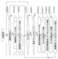
- FIG. 7 is a flowchart illustrating a route request packet reception process of the communication device according to the first embodiment.
- FIG. 8 is a flowchart showing evaluation reference value update and route evaluation value calculation processing in the first embodiment.
- FIG. 9 is a network configuration diagram according to the first embodiment.
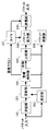
- FIG. 10 is a sequence diagram illustrating a case where a route search is requested by requesting data communication from the communication devices 901 to 904 in the first embodiment.
- FIG. 11 is a functional block diagram of a communication device according to the second embodiment.
- FIG. 12 is a flowchart illustrating a route request packet reception process of the communication device according to the second embodiment.
- FIG. 13 is a flowchart showing the evaluation reference value update and route evaluation value calculation processing in the second embodiment.
- FIG. 14 is a flowchart showing timer change processing of the communication device.
- FIG. 15 is a network configuration diagram according to the second embodiment.
- FIG. 16 is a sequence diagram illustrating a case where a route search is requested by requesting data communication from the communication devices 901 to 904 in the second embodiment.
- FIG. 17 is a functional block diagram of a communication device according to the third embodiment.
- FIG. 18 is a flowchart illustrating route request packet reception processing of the communication device according to the third embodiment.
- FIG. 19 is a flowchart illustrating route request packet transmission processing of the communication device according to the third embodiment.
- FIG. 20 is a network configuration diagram according to the third embodiment.
- FIG. 21 is a sequence diagram illustrating a case where a route search is requested by requesting data communication from the communication devices 901 to 904 in the third embodiment.
- FIG. 22 is a hardware diagram illustrating a hardware configuration of the communication apparatus.
- the start-point device that requests the start of communication searches for a route suitable for the data type for starting communication, it does not broadcast all the route request packets received by the relay device, but rather evaluates the route.
- the route request packet that has passed through the route having a high value is broadcast by the number set by the source device.
- the route evaluation value is a parameter used when selecting a route request packet. For a plurality of route request packets arriving at each relay device through different routes from the starting point device, the route evaluation value of the route passed by each route request packet It is a value indicating the state.
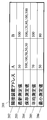
- FIG. 3 is a data format diagram of the route request packet.
- the route request packet 301 includes an end point address 302, a start point address 303, a route request packet number 304, a request route number 305, a condition identifier 306, an evaluation reference value 307, a relay device address 308, and an evaluation measurement value 309.
- the end point address 302 indicates the address of the end point device that is the connection destination from which the start point device requests communication.
- the starting point address 303 indicates the address of the starting point device.
- the route request packet number 304 is a value for identifying a route request packet transmitted from the same source device.
- the requested route number 305 is the number of routes set by the starting point device, and is set to an integer equal to or greater than “1”. However, when the end point device returns a route to the start point device, the requested route number is set to “0” because there is no required route.
- the condition identifier 306 is a parameter for specifying a condition for searching for a route, and is set by the starting point device. Each communication device changes the condition to be selected based on the condition identifier 306. In the present embodiment, the following six types are given as examples of condition identifiers.
- Condition identifier “1” Search for a route having the maximum bandwidth based on the latest communication state.
- Condition condition identifier “2” Based on the past communication state history, the minimum bandwidth value is a certain value or more.
- Condition condition identifier “5” for searching for a route Condition condition identifier “6” for searching for a route that guarantees that the communication continuation time between relay devices on the route is a certain value or more based on the latest communication state. : A condition for simultaneously searching for a route that guarantees that the minimum bandwidth value is equal to or greater than a certain value and a route that has the smallest number of hops based on the history of past communication states
- the evaluation reference value 307 is a value calculated based on the set value of the condition identifier 306. This value is used for route evaluation.
- the evaluation reference value 307 is used to compare a plurality of routes through which a route request packet having the same start point address 303 and route request packet number 304 has passed. For example, when the condition identifier is set to “1”, the evaluation reference value 307 is a communication band estimated from the latest communication state between the relay devices on the route from the start point device to the own device. It becomes.
- the evaluation reference value 307 is the minimum value on the path among the minimum band values measured for a certain period in the past between the relay apparatuses on the path.
- the evaluation reference value 307 is the time at which the source device transmits a route request packet. In this case, by synchronizing the clocks of all the devices in the network in advance, each device can select the route request packet based on the time difference between the time when the route request packet arrives and the time of the evaluation reference value 307. Can do.
- the evaluation reference value 307 is the number of hops from the starting point device.
- the evaluation reference value 307 is the communication duration time from the most recent time point when the communication device changes from the communication disabled state to the communication enabled state between the relay devices on the route. Of these, the minimum value on the route.
- the route request packet 301 has a plurality of evaluation reference values 307.
- a plurality of evaluation reference values 307 are expressed as evaluation reference value (1), evaluation reference value (2), and the like.
- the evaluation reference value (1) is the number of hops
- the evaluation reference value (2) is the minimum value of the band measured between each relay device on the route for a certain period in the past. Of these, the minimum value on the route.
- the relay device address 308 is an address of a relay device on the route from the start device to which the route request packet has passed.
- the evaluation measurement value 309 is information indicating the state of communication measured between each relay device and the relay device immediately before (one hop before).
- the relay device address 308 and the evaluation measurement value 309 are added each time the route request packet is relayed by each relay device.
- the measurement value 309 for evaluation is preferably stored in the route request packet 301 corresponding to the evaluation reference value 307 for convenience of processing.
- the evaluation measurement value 309 corresponding to the evaluation reference value (1) and the evaluation reference value (2), which are a plurality of evaluation reference values 307, are the evaluation measurement value (1) and the evaluation measurement value (2 ).
- the route request packet described above is used when the start device searches for a route, but is also used when the end device returns a route to the start device.
- a route request packet in which the end point device returns a route to the start point device is referred to as a return route request packet.
- the format of the reply route request packet is the same as that described above except that the start address and the end address of the route request packet are switched and the number of requested routes is set to “0”.
- FIG. 1 is a functional block diagram of a communication apparatus according to the first embodiment of the present invention.
- the communication apparatus according to the present embodiment includes a receiving unit 101, a measuring unit 102, an updating unit 103, a duplication detecting unit 104, a comparing unit 105, a packet storing unit 106, a timer 107, a packet discarding unit 108, and a transmitting unit. 109.
- the receiving unit 101 outputs a route request packet to the update unit 103 from data packets received by various communication methods.
- the measurement unit 102 measures information necessary for calculating the path evaluation value, and updates the measurement value management table 201 (details will be described later).
- the information necessary for calculating the path evaluation value includes the bandwidth in communication between the adjacent device (device capable of directly communicating with the own device) and the own device, and between the own device and the adjacent device.
- the communication continuation time from the latest time point when the communication is disabled to the communication enabled state until the present time.
- the measuring unit 102 measures the received power of a packet transmitted by a neighboring device arranged at a position where it can communicate directly from its own device, including packets other than the route request packet, and the neighboring device and its own device that have transmitted the packet. Estimate the bandwidth in communication between.
- the band here is a parameter representing a data communication speed such as a PHY (Physical Layer) rate, a MAC (Media Access Control) rate, and a throughput.
- the transmission unit 109 transmits a Hello packet indicating that the own apparatus exists on the network at a constant interval or at an arbitrary timing, and measures the communication duration time by receiving the Hello packet. As described above, the measured bandwidth and communication duration time are separately stored in the measured value management table 201.
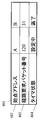
- FIG. 2 is a diagram illustrating an example of a measurement value management table.
- the measurement value management table 201 includes an adjacent device address 202, a latest measurement value 203, a stored measurement value 204, an average measurement value 205, and a minimum measurement value 206 for each adjacent device.
- the adjacent device address 202 is an address of an adjacent device that has transmitted the packet described in the header of the received packet.
- the latest measured value 203 is the latest value among the measured values measured by the measuring unit 102 between each adjacent device and the own device.
- the stored measurement values 204 are values stored in a new order in the order of measurement values measured by the measurement unit 102 between the adjacent device and the own device.
- the number of measurement values stored as the stored measurement values 204 can be changed based on the frequency of band fluctuation, the accuracy required for band estimation, and the like. Further, the number of measurement values stored as the stored measurement values 204 may be different for each adjacent device.
- the average measurement value 205 is an average value of a certain number of measurement values stored as the stored measurement value 204.
- the minimum measurement value 206 is the minimum value of a certain number of measurement values stored as the stored measurement value 204. For example, when the minimum value of the band is stored as the minimum measured value 206, the value is an index of how much the band can be guaranteed when the transmission path state between the communication apparatuses is the worst. Note that the minimum measurement value 206 does not need to be the minimum value of the band stored as the stored measurement value 204, and may be the minimum value of the measurement value estimated during a certain period.
- the update unit 103 When the route request packet has been transmitted from the communication device in the past, the update unit 103 outputs the route request packet to the packet discard unit 108 and discards it. On the other hand, if the route request packet has not been transmitted from the communication device in the past, the update unit 103 adds the measurement result of the measurement unit 102, updates the route request packet, and calculates a route evaluation value. Details of the route request packet update processing and the route evaluation value calculation processing will be described later. When updating the route request packet, the update unit 103 outputs the route request packet and the route evaluation value to the duplication detection unit 104.
- the duplication detection unit 104 determines whether or not the route request packet output from the update unit 103 is duplicated reception based on a duplication management table (details will be described later). After the determination, the duplicate detection unit 104 outputs the route request packet that is duplicate received and its route evaluation value to the comparison unit 105, and outputs the other route request packet and its route evaluation value to the timer 107.
- FIG. 4 is a diagram showing a duplication management table.
- the duplication management table 401 stores a start point address 402, a route request packet number 403, and a timer state 404 for each start point device.
- the starting point address 402 stores the address of the starting point device included in the received route request packet.
- the route request packet number 403 stores the route request packet number included in the received route request packet.
- the timer state 404 stores information indicating whether the timer 107 (details will be described later) is setting the timer or whether the timer has expired. Details of the determination processing of the duplication detection unit 104 using the duplication management table 401 will be described later.
- the comparison unit 105 refers to the route evaluation value of the route request packet output by the duplication detection unit 104 and the route evaluation value of all the route request packets stored by the packet storage unit 106 (details will be described later). It is determined whether the route request packet output by the duplication detection unit 104 and its route evaluation value are output to the packet storage unit 106 or output to the packet discard unit 108 and discarded. Details of the operation of the comparison unit 105 will be described later.
- the packet storage unit 106 stores the route request packet output from the comparison unit 105 and the timer 107. Also, the route evaluation value of the route request packet may be stored together. If the number of route request packets to be stored is larger than the requested route number 305 included in the route request packet, the packet with the smallest route evaluation value is updated from the stored route request packets.
- route request packets are transmitted from a plurality of start point devices, an area for storing the route request packets is secured for each start point address.
- the timer 107 receives the route request packet based on the condition identifier 306 included in the route request packet output from the duplication detection unit 104 and the route evaluation value of the packet, and then saves the packet in the packet storage unit 106.
- the waiting time until the route request packet is transmitted is calculated.
- the waiting time is calculated to be shorter as the route evaluation value of the route request packet is higher.
- the waiting time is a value proportional to the route evaluation value, a value inversely proportional to the time required to advance one hop so that each device can receive a route request packet that has passed through the relay device for one extra hop, or It is good also as time which added the stepwise value according to the route evaluation value.
- the timer 107 After calculating the standby time, the timer 107 starts a timer having the standby time as the timer length. Thereafter, the timer 107 outputs the route request packet to the packet storage unit 106. Furthermore, when the standby time expires, the timer 107 causes the transmission unit 109 to transmit a route request packet. Details of the operation of the timer 107 will be described later.
- the packet discard unit 108 discards the route request packet output by the update unit 103, the duplicate detection unit 104, and the comparison unit 105.
- the transmission unit 109 transmits data packets by various communication methods. However, the processing performed by the transmission unit 109 differs depending on whether the own device corresponds to the start point device, the relay device, or the end point device.
- the transmission unit 109 When the own apparatus corresponds to the starting point apparatus, the transmission unit 109 generates a new route control packet and broadcasts it.
- the transmission unit 109 broadcasts the packet stored by the packet storage unit 106 when the timer expires.
- the transmission unit 109 exchanges the end point address and the start point address of the route request packet, and generates a return route request packet in which the number of requested routes is set to “0”. Then, the transmission unit 109 returns the generated reply route request packet to the starting point device by unicast on the reverse route through which the original route request packet is relayed.
- FIG. 5 is a flowchart showing the processing.
- the communication apparatus determines whether or not there is a communication request indicating that the apparatus needs to communicate with another apparatus (STEP 501). If the communication device determines that there is a communication request, the communication device generates a route request packet to search for the route (STEP 502).
- FIG. 6 is a flowchart showing the route request packet generation process in STEP502.
- the transmission unit 109 sets the address of an end point device that is a connection destination as the end point address of a newly generated route request packet, and sets its own address as the start point address (STEP 601).
- the transmission unit 109 obtains a route request packet number 403 whose start address 402 is its own address from the duplication management table 401.
- the transmission unit 109 sets the value obtained by incrementing the acquired number to the route request packet number 304 of the newly generated route request packet (STEP 602).
- the transmission unit 109 increments the route request packet number 403 of the duplication management table 401 and updates the duplication management table 401 (STEP 603).
- the transmission unit 109 sets the requested route number 305 according to the scale of the network (STEP 604). Further, the transmission unit 109 sets a condition identifier 306 according to the type of data to be communicated (STEP 605). Finally, the transmission unit 109 prepares a necessary number of evaluation reference value 307 areas according to the condition identifier, and sets parameters that are not set in STEP 601 to STEP 605 as “0” or the transmission time of the route request packet. (STEP 606).
- the transmission unit 109 broadcasts the route request packet (STEP 503) and executes the processing of STEP 501.
- FIG. 7 is a flowchart showing the processing.
- the receiving unit 101 determines whether or not the received data packet is a route request packet (STEP 701). If the received data packet is not a route request packet (NO in STEP 701), the receiving unit 101 repeats the processing in STEP 701 until a route request packet is received. On the other hand, when the data packet received by the receiving unit 101 is a route request packet (YES in STEP 701), the following processing is executed in order.
- the update unit 103 determines whether or not its own address exists in the start point address 303 or the relay device address 308 included in the received route request packet (STEP 702). If the start address 303 or the relay device address 308 has its own address (YES in STEP 702), the update unit 103 determines that the received route request packet has been passed through the own device or generated by the own device. The route request packet is judged and output to the packet discard unit 108 to be discarded (STEP 713). On the other hand, when the own address does not exist in the start point address 303 or the relay device address 308 (No in STEP 702), the update unit 103 determines that the received route request packet has not passed through the own device before, and The following update processing is performed on the route request packet.
- the updating unit 103 After receiving the route request packet, the updating unit 103 updates the evaluation reference value included in the route request packet and calculates the route evaluation value (STEP 703).
- the evaluation reference value update process and the route evaluation value calculation process will be described later.
- the duplication detection unit 104 acquires the route request packet number 403 corresponding to the start point address 303 included in the route request packet output by the update unit 103 from the duplication management table 401. Then, the duplication detection unit 104 determines whether or not the route request packet number 304 of the route request packet output by the update unit 103 is smaller than the acquired route request packet number 403 (STEP 704). If the route request packet number 304 is smaller than the route request packet number 403 (YES in STEP 704), the received route request packet has been used for a past route search. By outputting to the packet discard unit 108, the packet is discarded (STEP 713).
- the duplication detection unit 104 determines whether or not the route request packet number 304 is equal to the route request packet number 403 (STEP 705).
- the duplication detection unit 104 receives the received route request packet for the first time. It is determined that Then, the duplication detection unit 104 updates the route request packet number 403 in the duplication management table 401 to the value of the route request packet number 304 included in the received route request packet (STEP 706).
- the timer 107 calculates a waiting time from the condition identifier 306 of the route request packet output by the duplication detection unit 104 and its route evaluation value (STEP 707). Then, the timer 107 updates the timer state of the duplication management table 401 to “setting” and starts a timer in which the calculated waiting time is set (STEP 708). Thereafter, the packet storage unit 106 stores the received route request packet (STEP 711). Further, the packet storage unit 106 increments the number of storage paths (STEP 712). After the completion of STEP 712, the processing of STEP 701 is executed.
- the duplication detection unit 104 determines that the received route request packet has been duplicately received, and further duplicates the management table 401. It is determined whether the timer state 404 stored in the state is “setting” or “expired” (STEP 709). When the timer state 404 is “expired” (STEP 709 “timer expired”), the duplication detection unit 104 discards the received route request packet by outputting it to the packet discard unit 108 (STEP 713). When the route request packet is discarded, the processing of STEP 701 is executed.
- the comparison unit 105 determines the route evaluation value of the received route request packet and the route request packet stored by the packet storage unit 106. Are compared with the route evaluation values (STEP 710).
- the comparison unit 105 It is determined whether or not the number of route request packets stored in the storage unit 106 is smaller than the number of request routes included in the received route request packet (STEP 714). When it is determined that the number of route request packets stored in the packet storage unit 106 is equal to the number of request routes (NO in STEP 714), the comparison unit 105 outputs the received route request packet to the packet discard unit 108. (STEP 713).
- the comparison unit 105 transmits the received route request packet to the packet storage unit 106.
- the packet storage unit 106 stores the route request packet (STEP 711). Further, the packet storage unit 106 increments the number of storage paths (STEP 712). After completion of STEP 712, the process returns to the route request packet reception process (STEP 701).
- the comparison unit 105 determines whether the number of route request packets stored in the packet storage unit 106 is smaller than the number of request routes included in the received route request packet (STEP 715). When the comparison unit 105 determines that the number of route request packets stored in the packet storage unit 106 is smaller than the number of request routes (YES in STEP 715), the packet storage unit 106 stores the route request packet ( (STEP 711), the number of storage paths is incremented (STEP 712). Then, the processing of STEP 701 is executed.
- the comparison unit 105 determines that the number of route request packets stored in the packet storage unit 106 is equal to the number of request routes (NO in STEP 715)
- the comparison unit 105 outputs the received route request packet to the packet storage unit 106.
- the packet storage unit 106 rewrites the route request packet having the smallest evaluation reference value 307 among the stored route request packets to the received route request packet (STEP 716). After the completion of STEP 716, the processing of STEP 701 is executed.
- the updating unit 103 acquires the immediately preceding relay device address related to the received route request packet by any of the following methods (STEP 800).
- Method 1 The relay device address described at the end of the relay device addresses 308 described in the route request packet is acquired.
- Method 2 When the own device is the first relay device, the start point address 303 is acquired instead of the relay device address 308.
- Method 3 If the address of the device that transmitted the route request packet is included in the packet header, the address is acquired as the immediately preceding relay device address.
- the update unit 103 acquires the condition identifier 306 included in the received route request packet (STEP 801). Then, the updating unit 103 adds its own address to the relay device address 308 included in the received route request packet (STEP 802). Then, the update unit 103 switches the subsequent processing according to the value of the condition identifier 306 included in the received route request packet (STEP 803).
- the update unit 103 acquires the latest measured value 203 of the band related to the adjacent device address 202 that is the same as the immediately preceding relay device address from the measured value management table 201 (STEP 805). Next, the update unit 103 adds the acquired latest measurement value 203 to the last evaluation measurement value (1) of the received route request packet (STEP 806). After that, the updating unit 103 calculates a bandwidth through the entire passage route using all evaluation values included in the received route request packet (STEP 807). The bandwidth through the entire passage route is calculated by obtaining the reciprocal of all the measurement values for evaluation (1) included in the route request packet and obtaining the reciprocal of the sum.
- the update unit 103 updates the evaluation reference value (1) of the received route request packet to the calculated bandwidth (STEP 808). Finally, a route evaluation value is calculated based on the evaluation reference value (1) (STEP 809). In this case, the update unit 103 calculates a value of the evaluation reference value 307 or a value obtained by normalizing the value as a route evaluation value. Thus, the evaluation reference value update and route evaluation value calculation processing is completed.
- the update unit 103 acquires, from the measurement value management table 201, the minimum measurement value 206 related to the adjacent device address 202 that is the same as the immediately preceding relay device address (STEP 810). .
- the update unit 103 acquires the evaluation reference value (1) included in the received route request packet (STEP 811).
- the updating unit 103 compares the evaluation reference value (1) included in the received route request packet with the minimum measured value 206 (STEP 812). When it is determined that the minimum measurement value 206 is smaller than the evaluation reference value (1) (Yes in STEP 812), the updating unit 103 updates the evaluation reference value (1) to the value of the minimum measurement value 206 (STEP 808).
- the evaluation reference value (1) is not updated. Then, the updating unit 103 calculates a value of the evaluation reference value (1) or a value obtained by normalizing the value as a route evaluation value (STEP 809). Thus, the evaluation reference value update and route evaluation value calculation processing is completed.
- the updating unit 103 uses the time difference between the time when the route request packet arrives at its own device and the time of the evaluation reference value or a value obtained by normalizing the time difference as the route evaluation value. Calculate (STEP 809), and the process is terminated.
- the updating unit 103 acquires the evaluation reference value (1) included in the received route request packet and increments the value (STEP 804). Then, the updating unit 103 updates the evaluation reference value (1) to an incremented value (STEP 808). Next, the updating unit 103 calculates a value that increases as the hop number decreases, for example, the reciprocal of the hop number, or a value obtained by normalizing the reciprocal as a route evaluation value (STEP 809), and ends the process.
- the updating unit 103 increments the evaluation reference value (1) among the evaluation reference values 307 included in the received route request packet (STEP 813).
- the update unit 103 acquires the minimum measurement value 206 related to the adjacent device address 202 that is the same as the immediately preceding relay device address from the measurement value management table 201 (STEP 814).
- the update unit 103 acquires the evaluation reference value (2) among the evaluation reference values 307 included in the received route request packet (STEP 815), and compares the minimum measurement value 206 with the evaluation reference value (2) ( (STEP 816).
- the updating unit 103 updates the evaluation reference value (2) to the minimum measurement value 206 (STEP 808). Then, the update unit 103 calculates the updated evaluation reference value (1), the route evaluation value (1) and the route evaluation value (2) corresponding to the evaluation reference value (2) (STEP 809), and ends the processing. To do. On the other hand, when it is determined that the minimum measured value 206 is larger than the evaluation reference value (2) (No in STEP 816), the update unit 103 determines the route evaluation value (1) corresponding to the evaluation reference value (1), the original The route evaluation value (2) corresponding to the evaluation reference value (2) is calculated (STEP 809), and the process is terminated.
- the communication device determines that there is no communication request (NO in STEP 501)
- the communication apparatus executes the processing of STEP 501.
- the communication apparatus executes the processing of STEP 512.
- the communication device determines whether or not the end address of the route request packet is its own address (STEP 512). If it is determined that the end point address is its own address (YES in STEP 512), the communication device generates a return route request packet for returning the route to the start point device (STEP 513).
- the process for generating the return route request packet is as follows. First, the communication apparatus switches the end point address and the start point address in the route request packet whose end point address is its own address. Next, the communication apparatus sets the number of request routes of the route request packet to “0”.
- the communication apparatus updates the timer state 404 of the duplication management table 401 to “expired” (STEP 514). Then, the communication device unicasts the return route request packet (STEP 515), and executes the processing of STEP 511.
- the communication apparatus updates the timer state 404 of the duplication management table 401 to “expired” (STEP 516).
- the communication apparatus broadcasts the route request packet stored in the packet storage unit 106 (STEP 517), and executes the processing of STEP 511.
- PLC Power Line Communication
- FIG. 9 is a diagram showing a network configuration in the present embodiment.
- the network according to the present embodiment includes communication devices 901 to 906.
- the communication devices 901 to 906 are referred to as nodes A to F in alphabetical order in accordance with the order of the codes.
- the addresses of the communication devices 901 to 906 are assumed to be A to F in alphabetical order in accordance with the order of the codes.
- each communication device refers to a PLC modem, and communicates voice, moving images, normal data, and the like with other devices.
- the node A starts data communication with the node D that cannot communicate directly
- the node A is called a start point node
- the node D is called an end point node.
- Node A searches for a route by specifying conditions according to the type of data to be communicated.
- the following conditions are used as an example of conditions according to the data type.
- the condition that the delay between the start node and the end node is minimum or the number of hops is minimum is used.
- the condition that the minimum guaranteed bandwidth of the route is the maximum is used.
- the condition that the path bandwidth is maximum or the communication connection time is long is used.
- FIG. 10 is a sequence diagram when data communication is requested from the node A to the node D and the node A searches for a route to the node D in the present embodiment.
- a portion where transmission and reception are displayed with a frame indicates transmission and reception processing at each node and its identification number, and a dotted arrow between them indicates that a route request packet is transmitted by broadcasting.
- the symbol and number enclosed in a square frame on the dotted arrow indicate the contents of the transmitted route request packet, and the address of the node that has passed from the start node to the node (hereinafter referred to as the transit node address) and its Represents the evaluation standard value of the route.
- a cross mark at the destination of the route request packet indicates that the route request packet received by any of the update unit 103, the duplicate detection unit 104, and the comparison unit 105 of the node is discarded.
- the bold line from the reception of the route request packet to the transmission at each node indicates the waiting time as shown in the legend.
- the passing node addresses of both the route request packet received and updated by each node and the route request packet received and stored in advance by the packet storage unit 106 are displayed.
- the updated evaluation reference value is displayed surrounded by a frame.
- the route request packet stored by the packet storage unit 106 after the update is displayed surrounded by a solid frame
- the route request packet discarded after the update is displayed surrounded by a dotted frame.
- the one-dot chain arrow from node D which is the end node, indicates that a reply route request packet has been returned to the start node by unicast.
- Node A creates a route request packet based on the processing shown in FIG. 6 and transmits it to another node when a communication start request occurs.
- the route request packet transmitted by the node A will be described in detail on the assumption that the number of requested routes is “1”, the condition identifier is “1”, and the route request packet number to be transmitted is “120”.
- nodes B, F, and C When node A transmits a route request packet (transmission 1), nodes B, F, and C receive the route request packet (reception 1, reception 2, reception 3). The nodes B, F, and C update the evaluation reference value and calculate the route evaluation value for the received route request packet based on the method shown in FIG. First, since the condition identification value of the received route request packet is set to “1”, the nodes B, F, and C are the same as the address A that is the address of the node A from the measurement value management table 201 of FIG. The latest measured value 203 related to the band of the adjacent device address 202 is acquired. Here, since the latest bandwidth between the nodes is as shown in FIG.
- the latest bandwidth acquired by the node B is 100
- the latest bandwidth acquired by the node C is 5, and the latest bandwidth acquired by the node F.
- the bandwidth is 50.
- the nodes B, F, and C calculate the evaluation reference value and the route evaluation value based on the acquired latest band.
- the calculated evaluation reference value and the route evaluation value are the latest measured value 203.
- the node B adds “B, 100” to the relay device address and evaluation measurement value of the received route request packet, and updates the evaluation reference value to “100” (lower left of “reception 1”).
- node F adds “F, 50” to the relay device address and evaluation measurement value of the received route request packet, and updates the evaluation reference value to “50” (lower left of “Reception 2”).
- node C adds “C, 5” to the relay device address and evaluation measurement value of the received route request packet, and updates the evaluation reference value to “5” (lower left of “Reception 3”).
- the nodes B, F, and C store “A” as the start point address 402 and “120” as the route request packet number 403 in the duplication management table 401. Further, the nodes B, F, and C determine the waiting time until the route request packet is transmitted according to the route evaluation value calculated as described above, and set a timer for the waiting time. Here, since the shorter standby time is set as the route evaluation value is higher, shorter standby times are set in the order of the nodes B, F, and C.
- the node B whose timer has expired broadcasts the stored route request packet (transmission 2).
- the relay device address, the measurement value for evaluation are set to “B, 100”, and the evaluation reference value is set to “100”.
- Node A receives this route request packet (reception 100), but discards the received route request packet because the start point address included in the received route request packet is its own address. This process prevents a loop route from being generated and prevents a useless route request packet from being broadcast. Further, since the node A does not perform unnecessary determination such as comparison of route evaluation values, the processing load is reduced.
- the node E Since the received route request packet is the first route request packet, the node E adds “E, 50” to the relay device address and the evaluation measurement value of the received route request packet by the same processing as described above, and evaluates it.
- the reference value is updated to “33” (lower left of “reception 6”). Then, a timer is set according to the calculated waiting time.
- the node F receives the received route request packet in duplicate. Make sure that In this case, the node F compares the route evaluation value (50) of the route request packet received and stored first with the route evaluation value (50) of the route request packet received second. Since the number of requested routes is set to “1”, the node F needs to store a route request packet having a large route evaluation value and discard a route request packet having a small route evaluation value. Request packets have the same path evaluation value.
- the node F stores the route request packet having the smaller number of hops among these route request packets, that is, the route request packet received first, as it is, and discards the route request packet received second (“Reception 4”). ”Lower left).
- the node F stores the route request packet having the smaller number of hops among these route request packets, that is, the route request packet received first, as it is, and discards the route request packet received second (“Reception 4”). ”Lower left).
- node C adds “C, 11” to the relay device address and evaluation measurement value of the received route request packet, and updates the evaluation reference value to “10” (lower left of “reception 5”).
- the route evaluation value (10) of the route request packet received second is larger than the route evaluation value (5) of the route request packet received and stored first. Therefore, the node C stores the second received route request packet having the relay device address, the evaluation measurement values “B, 100”, “C, 11”, and the evaluation reference value “10” (“Reception”). 5 ”, lower left).
- the node F whose timer has expired secondly broadcasts the stored route request packet having the relay device address, the evaluation measurement value “F, 50”, and the evaluation reference value “50” ( Transmission 3).
- the node A receives the route request packet (reception 101)
- the node A discards the route request packet because the received route request packet includes its own address.
- nodes C and E receive the packet (reception 7 and reception 8)
- they update the packet to be saved to the received route request packet.
- the node B receives the route request packet after the timer expires (reception 102), it discards it.
- each node discards the route request packet received after the timer expires, so that the processing load on each device is reduced.
- the next relay apparatus does not need to process a route request packet having the same start point address and end point address after the timer expires.
- the node D which is the end point device, when the timer expires, the relay device address and the evaluation value are “F, 50”, “E, 200”, “D, 200”, and the route evaluation value is “ 33 ”, the second received route request packet is stored (lower left of“ Reception 10 ”).
- the node D swaps the end point address and start point address of this packet, generates a return route request packet with the number of requested routes set to “0”, and starts from the reverse route on which the original route request packet was relayed Unicast transmission to (transmission 6). In this way, the communication route is set by returning the route request packet finally determined by the end point node to the start point node.
- the timer 107 sets a predetermined waiting time from the reception of the first route request packet, and among the route request packets received by the duplication detection unit 104 within the waiting time. It is determined whether the route request packet has been received in duplicate. In the case of duplicate reception, the comparison unit 105 selects a route request packet having a high route evaluation value by the number of requested routes. Then, the transmission unit 109 transmits the selected route request packet to the adjacent device. As a result, a route having a high route evaluation value indicating the state of the route is created between the start point device and the end point device while reducing the number of route request packets transmitted for route search and suppressing bandwidth consumption. be able to.
- the timer 107 sets a waiting time according to the route evaluation value calculated from the received route request packet. As a result, the timing at which each device transmits the route request packet can be distributed, so that the possibility that the route request packet transmitted by each device will collide is reduced compared to the case where the waiting time is fixed. it can.
- the timer 107 sets the standby time longer as the route evaluation value calculated from the route request packet received first is lower.
- each device can increase the possibility of receiving another route request packet via a route with a high route evaluation value when the route evaluation value with the start point device is low. Can more reliably search for a route having a high route evaluation value.
- the start device can set the number of route request packets, and the relay device transmits the number of route request packets as many as the number of route requests.
- the number of paths created by the start-point device can be increased to reduce the possibility that communication cannot be performed on all paths.
- it is possible to limit the number of packets transmitted for route creation by reducing the number of routes created by the source device. Therefore, it is possible to achieve both stable communication and reduced bandwidth consumption.
- the format of the route request packet may be extended as described below.
- the route request packet 301 may not include the evaluation measurement value 309. Thereby, since the packet length of the route request packet is shortened, the bandwidth consumed by the transmission of the route request packet can be further reduced. For example, when the condition identifier is set to “2” or “5”, the minimum value on the route regarding the specific communication state becomes the evaluation reference value 307, and each relay apparatus has its own measured value and its minimum value.
- the condition identifier is set to “3”, the evaluation value 309 is not necessary because the relay device does not need to update the evaluation reference value 307 after the start point device sets the value of the evaluation reference value 307. .
- the condition identifier is set to “4”, since each relay device only adds 1 to the evaluation reference value 307 after the starting point device sets the value of the evaluation reference value 307 to 0, the measurement value 309 for evaluation Is not necessary.
- the evaluation reference value 307 required when the condition identifier is set to “2” and “5” may be calculated. unnecessary. Therefore, only when the condition identifiers “1” to “6” are set to “1”, the route request packet 301 always includes the measurement value 309 for evaluation, and the measurement value 309 for evaluation is included in each relay device. And the latest communication band measured between the relay device and the immediately preceding relay device.
- the route request packet 301 may additionally include the measurement value 309 for evaluation. Further, the route request packet 301 may not include the evaluation reference value 307 instead of including the specific communication state between the relay devices as the evaluation measurement value 309. In this case, each relay device calculates an evaluation reference value 307 based on the value of the measurement value 309 for evaluation.
- the route request packet 301 may include the latest measurement value 203 instead of the minimum measurement value 206 as the measurement value 309 for evaluation. Good.
- the latest bandwidth through the entire route can be calculated and used as the next selection criterion.
- condition identifier 306 is not limited to the six types described above.
- an average bandwidth value may be added based on the past communication state history.
- the measurement unit 102 of each device adds a transmission time to the Hello packet transmitted between the own device and the adjacent device, periodically measures the delay time, An average value or a maximum value within the time may be obtained, and the sum total between the relay devices on the route through which the route request packet has passed is calculated and used as the evaluation reference value.
- the condition identifier “5” may also use an average value or a minimum value of the communication continuation time based on the past communication state history.
- the start point device may search for an optimum route from a combination of a plurality of conditions.
- the starting point device sets identifiers representing a plurality of conditions in the condition identifier 306 of the route request packet 301 and sets values indicating the states of the plurality of routes corresponding to these conditions in the evaluation reference value 307.
- each device satisfies two requirements: the priority order of a plurality of conditions can be identified, and each device can identify which of the condition identifiers each evaluation criterion value set in the evaluation criterion value 307 corresponds to. There is a need.
- condition identifiers 306 are set with condition identifiers in order of priority among the plurality of conditions, and evaluation reference values 307 correspond in order of priority.
- the evaluation reference values may be set in order.
- the condition identifier 306 when searching for a route with a minimum number of hops when the bandwidth is the maximum based on the latest communication state and the bandwidth value is the same for a plurality of routes, the condition identifier 306 is “1” or “4”.
- two areas of the evaluation reference value (1) and the evaluation reference value (2) are secured in the evaluation reference value 307, and the evaluation reference value (1) includes the latest communication state between each relay device on the route.
- the communication band estimated from the starting point device to the own device is stored, and the number of hops is stored in the evaluation reference value (2). Further, an evaluation measurement value (1), which is an evaluation measurement value 309 corresponding to the evaluation reference value (1), is also secured, and the evaluation measurement value (1) includes each relay device and the relay device immediately preceding it. The latest communication bandwidth measured during the period is stored.
- the transmission unit 109 may collectively describe and transmit the contents of the plurality of route request packets.
- the standby time is set by the route request packet first received by each device, and the standby time is not updated thereafter.
- the waiting time set by the route request packet received first is not always appropriate. For example, if the set standby time is too long, the standby time until each relay device transmits a route request packet becomes long, and a long time is required until the route is set. As a result, the start of data communication is delayed. On the other hand, if the set standby time is too short, there is a higher possibility of discarding a route request packet having a higher route evaluation value after the standby time has elapsed.
- the communication apparatus in order to set a route with a high route evaluation value as soon as possible, waits when the route evaluation value of the received route request packet satisfies a certain condition. Reduce time.
- a route request packet is transmitted without waiting for the timer to expire will be described.
- FIG. 11 is a functional block diagram of a communication apparatus according to the second embodiment of the present invention. 11 is the same in number and type as in FIG. 1, but in this embodiment, since the comparison unit 105 updates the timer 107 or refers to the value of the timer 107, the comparison unit 105 A timer 107 is directly connected.
- each configuration of the present embodiment shown in FIG. 11 differs only in the operation of the comparison unit 105.
- the comparison unit 105 compares the waiting time, the route evaluation value, and the number of hops of the newly received route request packet and the previously received route request packet, under a predetermined condition.
- the waiting time of the timer 107 is shortened and extended. Further, the comparison unit 105 expires the standby time set in the timer 107 when the same route request packet is received by the start point device and the end point device by the number of a predetermined threshold.
- the evaluation reference value (0) is added as an area in which the number of hops is described in the evaluation reference value 307. Further, the route request packet 301 may include a flag indicating that the expiration time of the timer has been extended. In this case, the timer 107 of another device that has detected that the flag indicating that the expiration time of the timer has been extended is set in the route request packet is transmitted later by the device that transmitted the route request packet. In order to receive a route request packet with a high route evaluation value, a new timer may be set.
- FIG. 12 is a flowchart showing route request packet reception processing executed by each device according to the present embodiment.
- FIG. 12 the same processing as the reception processing in the first embodiment shown in FIG. Here, differences from FIG. 7 will be described.
- STEP 1201 is processing corresponding to STEP 703 in FIG.
- the updating unit 103 performs evaluation reference value update and route evaluation value calculation processing (STEP 1201).
- FIG. 13 is a flowchart showing the processing of STEP1201. In FIG. 13, the same processes as those in the evaluation reference value update and route evaluation value calculation process in the first embodiment shown in FIG. Here, differences from FIG. 8 will be described.
- the update unit 103 increments the evaluation reference value (0) (STEP 1301). This is because, in the second embodiment, the number of hops is used for route search regardless of the condition identifier.
- the updating unit 103 updates the evaluation reference value (0) together with other evaluation reference values when updating the evaluation reference value (STEP 1302).
- the update unit 103 calculates a route evaluation value related to the evaluation reference value (0) as a second route evaluation value together with other route evaluation values (STEP 1303).
- the updating unit 103 uses a value that increases as the hop number decreases, for example, a reciprocal number of hops, or a value obtained by normalizing the reciprocal number. Calculate as In the following description, a route evaluation value other than the second route evaluation value will be referred to as a first route evaluation value.
- the first route evaluation value is the same as the route evaluation value in the first embodiment.
- the value of the evaluation reference value (0) May be used instead of the evaluation reference value (1). Therefore, as indicated by a dotted line in FIG. 13, the processing of STEP 804 and STEP 813 may be omitted, and the value of the evaluation reference value (0) may be used in the subsequent processing.
- FIG. 14 is a flowchart showing timer change processing executed by the comparison unit 105.
- the comparison unit 105 increments the number of received route request packets indicating how many route request packets having the same start point address and route request packet number have been received (STEP 1401). In this case, in order to store the number of received route request packets, it is desirable that the number of received route request packets is added to the constituent elements of the duplication management table 401.
- the comparison unit 105 determines whether or not the number of received route request packets is equal to or greater than a threshold (STEP 1402).
- the predetermined threshold value is a number that can receive a sufficient number of route request packets to create a route having a high route evaluation value. This threshold value is typically stored in advance in each device. Note that the starting point device may store the threshold separately in the route request packet 301. Further, only how many times the threshold corresponds to the number of requested routes 305 is set in common for each device, and each device may calculate the threshold according to the number of requested routes 305 determined by the starting device. .
- a mode may be used in which each device steadily measures a route request packet relayed by itself and determines an optimum threshold value for the number of route request packets by learning. If it is determined that the number of received route request packets is equal to or greater than the threshold (YES in STEP 1402), the comparison unit 105 expires the previously set timer (STEP 1403) and ends the timer change process.
- the comparing unit 105 acquires the first route evaluation value of the received route request packet (STEP 1404).
- the comparison unit 105 determines whether the acquired first route evaluation value is larger than any of the first route evaluation values in all route request packets stored in the packet storage unit 106 ( (STEP1405).
- the comparison unit 105 acquires the second route evaluation value of the received route request packet (STEP 1406). Next, the comparison unit 105 determines whether the acquired second route evaluation value is smaller than any second route evaluation value in all route request packets stored in the packet storage unit 106. (STEP1407).
- the comparison unit 105 calculates a standby time based on the acquired first route evaluation value (STEP 1408). Next, the comparison unit 105 sets a new timer based on the calculated standby time (STEP 1409), and ends the timer change process.
- the comparison unit 105 When it is determined that the acquired second route evaluation value is greater than or equal to the second route evaluation value of any route request packet stored in the packet storage unit 106 (No in STEP 1407), the comparison unit 105 The standby time is calculated based on the acquired first route evaluation value (STEP 1413). Next, the comparison unit 105 compares the calculated standby time with the remaining time of the currently set timer (STEP 1414). When the calculated waiting time is shorter than the remaining time of the currently set timer, the comparison unit 105 updates the currently set timer to the calculated waiting time (STEP 1415), and ends the timer changing process. On the other hand, when the calculated standby time is equal to or longer than the remaining time of the currently set timer (NO in STEP 1414), the comparison unit 105 ends the timer changing process as it is.
- the comparison unit 105 acquires the first route evaluation value. It is determined whether or not the first route evaluation value of the route request packet is smaller than any first route evaluation value in all route request packets stored in the packet storage unit 106 (STEP 1410). When it is determined that the acquired first route evaluation value is equal to the first route evaluation value of any route request packet stored in the packet storage unit 106 (No in STEP 1410), the comparison unit 105 directly performs a timer. End the change process.
- the comparison unit 105 acquires the second route evaluation value of the received route request packet (STEP 1411). Next, the comparison unit 105 determines whether the acquired second route evaluation value is smaller than any second route evaluation value in all route request packets stored in the packet storage unit 106. (STEP 1412). When it is determined that the acquired second route evaluation value is smaller (YES in STEP 1412), the comparison unit 105 expires the timer (STEP 1403) and ends the timer change process. On the other hand, when it is determined that the acquired second route evaluation value is greater than or equal to the second route evaluation value of any route request packet stored in the packet storage unit 106 (No in STEP 1412), the comparison unit 105 Ends the timer change process.
- FIG. 15 is a diagram showing a network configuration in the present embodiment.
- apparatuses that can directly communicate are connected by a solid line.
- the numerical value described for each solid line indicates the latest communication band that can be expected between the two devices connected by the solid line.
- the communication devices 901 to 906 are referred to as nodes A to F in alphabetical order in accordance with the order of the codes.
- the addresses of the communication devices 901 to 906 are assumed to be A to F in alphabetical order in accordance with the order of the codes.
- the node A starting node
- searches for a route by designating conditions according to the data type communicated with the node D (ending node) that cannot directly communicate is described below as an example. explain.
- FIG. 16 is a sequence diagram when a data communication start request is generated from the node A to the node D and the node A searches for a route to the node D in the present embodiment.
- the symbols written in the same form as in FIG. 10 indicate the same contents as in FIG. 10.
- the contents described in the legend are different from those in FIG.
- the standby time A indicates the standby time set based on the route evaluation value of the route request packet received first.
- the shortening time of the waiting time A indicates the length of time that the waiting time A has been shortened by the processing of STEP 1403 or STEP 1415 in FIG.
- the waiting time A is shortened once, after the waiting time A is once shortened, the processing of STEP 1403 or STEP 1415 in FIG. 14 is performed again, so that the waiting time A is further reduced in addition to the shortening time of the waiting time A.
- the waiting time B indicates the waiting time of the timer newly set by the processing of STEP 1409 in FIG.
- the shortening time of the waiting time B indicates the length of time that the waiting time B is shortened by performing the processing of STEP 1403 or STEP 1415 in FIG. 14 after the timer of the waiting time B is set.
- the threshold value of the number of route request packets received during the standby time (the threshold value of STEP 1402 in FIG. 14) is set to “4”, and each relay device has the fourth route even if the timer does not expire.
- the route request packet stored at that time is transmitted.
- Node A creates a route request packet when a data communication start request is generated.
- the route request packet 301 transmitted by the node A has the route request packet number 304 set to “120”, the requested route number 305 set to “1”, and the condition identifier 306 set to “1”.
- the evaluation reference value (0) of the evaluation reference value 307 is set to “0” as an initial value.
- the evaluation reference value (1) is an area in which the route evaluation value calculated by each relay apparatus based on the condition identifier is described, and “0” is set as an initial value.
- nodes B, F, and C When node A transmits a route request packet (transmission 1), nodes B, F, and C receive the route request packet (reception 1, reception 2, reception 3). Each of the nodes B, F, and C increments the evaluation reference value (0) included in the received route request packet and updates it to “1”. Next, when the node determines that the condition identifier of the received route request packet is set to “1”, the node sets its own address as the relay node address included in the received route request packet, and the measurement value for evaluation. The latest communication band with node A acquired from the measured value management table 201 is added to (1). Further, the evaluation reference value (1) included in the route request packet is updated to the latest band when communication is performed with the node A acquired from the measurement value management table 201.
- a standby time is calculated based on the evaluation reference value (1), and a timer is set.
- the timers of the nodes B, F, and C are set so that the standby time expires in the order of the nodes B, F, and C.
- the time obtained by adding the standby time A and the shortened time of the standby time A is the standby time set at this point.
- Node B whose waiting time has expired first has the stored relay device address and evaluation measurement value (1) “B, 100”, evaluation reference value (0) “1”, and evaluation reference value (1). Broadcasts a route request packet set to "100" (transmission 2).
- Each of the nodes F, C, E receives this route request packet (reception 4, reception 5, reception 6). Then, these nodes increment the evaluation reference value (0) included in the received route request packet and update it to “2”. Next, when the node determines that the condition identifier of the received route request packet is set to “1”, the node sets its own address as the relay device address included in the received route request packet, and the measurement value for evaluation. The latest communication band with the node B acquired from the measured value management table 201 is added to (1). Further, the nodes F, C, and E calculate a band when communication is performed on the route based on the value stored in the measurement value for evaluation (1), and update the evaluation reference value (1) to the calculated band. To do.
- the node F sets the evaluation reference value (0) included in the received route request packet to “2”, the evaluation reference value (1) to “33”, the relay device address and the measurement value for evaluation. (1) is updated to “B, 100”, “F, 50” (lower left of “Reception 4”).
- the route request packet received second by the node F satisfies the condition that the evaluation reference value (1) is small, that is, the first route evaluation value is small.
- the route request packet satisfies the condition that the number of hops is larger than the route request packet received by the node F first, that is, the second route evaluation value is also small.
- the node F updates the timer state 404 of the duplication management table 401 to “expired” and transmits the first received route request packet stored at this timing (transmission) 3).
- the shortening time of the waiting time A shows the waiting time shortened by this.
- the node C After receiving the route request packet transmitted by the node B (Reception 5), the node C sets the evaluation reference value (0) included in the received route request packet to “2” and the evaluation reference value (1) to “33”.
- the relay device address 308 and the measurement value for evaluation (1) are updated to “B, 100” and “C, 50” (lower left of “Reception 5”).
- the route request packet received second satisfies the condition that the evaluation reference value (1) is large, that is, the first route evaluation value is large.
- the route request packet satisfies the condition that the number of hops is larger than that of the route request packet initially received and stored by the node C, that is, the second route evaluation value is small.
- the node C also calculates a standby time for the received route packet, and sets a second timer based on the calculated standby time. At this time, since the expiration time of the second timer is later than the expiration time of the first timer, the standby time is extended. In FIG. 16, the time obtained by adding the standby time B and the shortened time of the standby time B is the standby time determined by the second timer.
- the node C once transmits a route request packet stored up to that time at the expiration time of the first timer (transmission 4), and the first timer at the expiration time of the second timer.
- the route request packet received and stored after the expiration time of is transmitted (transmission 6).
- the node C does not update the timer state 404 of the duplication management table 401 as “setting” when the first timer expires, and updates it to “expire” when the second timer expires.
- the node C receives the route request packet transmitted by the node F (transmission 3) (reception 7), sets the evaluation reference value (0) of the received route request packet to “2”, and the evaluation reference value (1). Is updated to “9” (lower left of “reception 7”). Since the evaluation reference value (1) of the received route request packet is lower than the evaluation reference value (1) of the second received route request packet, the node C discards this route request packet.
- the route request packet is the first received route request packet, so the route request packet is updated and saved. And set the timer.
- a time obtained by adding the standby time A, the shortening time of the standby time A, and the re-shortening time of the standby time A is the standby time set at this time.
- the node E receives the route request packet transmitted by the node F (transmission 3) (reception 8), sets the evaluation reference value (0) of the received route request packet to “2”, and the evaluation reference value (1). Is updated to “55” (lower left of “reception 8”). Since the first route evaluation value of the route request packet received this time is higher than the first evaluation reference value of the route request packet received first, the node E calculates the waiting time for the route request packet received this time. . Since the expiration time of the timer based on the currently calculated waiting time is earlier than the timer expiration time already set, the node E updates the timer according to the timer expiration time based on the currently calculated waiting time. . In FIG. 16, the shortening time of the waiting time A shows the waiting time shortened by this.
- the node E receives the first route request packet transmitted by the node C (transmission 4) (reception 9). Then, the node E updates the evaluation reference value (0) of the received route request packet to “3” and the evaluation reference value (1) to “28” (lower left of “reception 9”). Since the route request packet received this time has a smaller evaluation reference value (1) and a larger number of hops than the route request packet received this time, the first and second route evaluation values are both small. Therefore, the evaluation reference value (0) is set to “2”, the evaluation reference value (1) is set to “55”, the relay device address and the measurement for evaluation without waiting for the timer set once after shortening the waiting time. A route request packet having values (1) set to “F, 75” and “E, 200” is transmitted (transmission 5). In FIG. 16, the waiting time A is shortened again by this time.
- the node D When the node D receives the first route request packet transmitted by the node C (transmission 4) (reception 10), the received packet is the first route request packet, and therefore updates and stores the route request packet. Set the timer. In FIG. 16, the time obtained by adding the standby time A and the shortened time of the standby time A is the standby time set at this point.
- the route request packet transmitted by the node E (transmission 5) is received (reception 12)
- the evaluation reference value (0) of the received route request packet is set to “3”, and the evaluation reference value (1) is set to “1”. 35 ”(lower left of“ reception 12 ”).
- the node D Since the evaluation reference value (1) of the route request packet received later is higher than the evaluation reference value (1) of the route request packet received first, the first route evaluation value of the route request packet received later is the first. Higher than the first route evaluation value of the route request packet received at Therefore, the node D calculates the waiting time for the route request packet received later. However, since the expiration time of the timer based on the waiting time calculated later is later than the expiration time of the timer that has already been set, the node D does not update the timer and receives the route request packet to be stored this time. Update to packet.
- the node C that has received the route request packet transmitted by the node E (transmission 5) (reception 11) sets the evaluation reference value (0) of the received route request packet to “3” and the evaluation reference value (1). Update to “43” and save (lower left of “Reception 11”). Since the route request packet received this time is the fourth route request packet, the node C transmits the stored route request packet without waiting for the second timer expiration (transmission 6), and the duplication management table.
- the timer state 404 of 401 is updated to “expired”. In FIG. 16, the waiting time B is shortened from the waiting time initially set by the second timer.
- node C When node C transmits a route request packet for the second time (transmission 6), node D receives it (reception 13), sets the evaluation criterion value (0) of the received route request packet to “4”, and evaluation criterion The value (1) is updated to “30” (lower left of “reception 13”). Since the route request packet received this time has a smaller evaluation reference value (1) and a larger number of hops than the route request packet received second, both the first and second route evaluation values become smaller.
- the node D does not wait for the timer set first to expire, replaces the end point and start address of the stored packet, generates a route request packet with the number of requested routes set to “0”,
- the unicast transmission is performed to the starting node A via the reverse route through which the route request packet of the above is relayed (transmission 7).
- the waiting time A is shortened by this shortening time.
- the waiting time expiration time set based on the route request packet received later is set to be higher than the waiting time expiration time set based on the route request packet received earlier. If it is early, the communication device shortens the timer length. As a result, since the route evaluation value calculated from the previously received route request packet is low, even when a route request packet with a high route evaluation value is received after a long waiting time is set, the communication device High route request packets can be transmitted quickly. For this reason, it is possible to prevent the next relay device from selecting and transmitting only the route request packet received from another device because the route request packet from the own device is not received in time. Therefore, there is a high possibility that a route request packet having a high route evaluation value is transmitted to the next relay device, and a route having a high route evaluation value can be created more reliably.
- the communication device when a threshold value that is sufficient to create a route with a high route evaluation value is defined and a route request packet that is equal to or greater than the threshold value is received, the communication device has received the route received so far.
- the route request packet is transmitted without waiting for the waiting time set based on the request packet to expire. Accordingly, the communication device can transmit the selected route request packet to the next relay device when a sufficient number of request packets are received to create a route with a high route evaluation value. Therefore, it is possible to prevent the next relay device from selecting and transmitting only the route request packet received from the other device before the own device transmits the route request packet. Can be created reliably.
- the number of hops calculated from the route request packet received after the second is larger than the number of hops calculated from the route request packet received so far, and the first calculated from the route request packet received after the second
- the communication device transmits the route request packet without waiting for the end of the standby time set so far.
- the communication device transmits the route request packet as soon as the number of hops increases and the first route evaluation value decreases, so that the waiting time is not set unnecessarily, and the route request packet is transmitted quickly. can do. Therefore, it is possible to prevent the next relay device from selecting and transmitting only the route request packet received from another device until the own device transmits the route request packet, and a route with a high route evaluation value can be more reliably obtained. Can be created.
- the number of hops calculated from the newly received route request packet is greater than the number of hops calculated from the request packet received so far, and the first evaluation reference value calculated from the newly received route request packet is this. If it is larger than the first evaluation reference value calculated from the route request packet received so far, the communication device extends the waiting time and waits for reception of another request packet. Thus, when the number of hops increases and the first route evaluation value also increases, the route request packet route received in the future has more hops than the route request packet route received so far. It is considered that the evaluation value may be improved.
- the communication apparatus can reduce the transmission omission of a route request packet with a higher route evaluation value received after the standby time set before the extension has expired, and more reliably create a route with a higher route evaluation value. be able to. Therefore, when the waiting time set based on the request packet received so far has elapsed, the route request packet is transmitted to another relay device, and the request packet having a higher route evaluation value received thereafter cannot be selected. Therefore, a route with a high route evaluation value can be created more reliably.
- the timer setting is only given up to twice. However, after the timer setting has already been set twice or more, the number of hops of the newly received route request packet is large, and the route evaluation is performed. When the value is also large, the timer setting may be performed three times or more.
- the present invention can be similarly applied to a case where an optimum route is searched from a combination of a plurality of conditions.
- the evaluation reference value (2) and later and the evaluation measurement value (2) and later of the evaluation measurement value 309 are used, and the same processing may be performed using the highest priority route evaluation value and the number of hops.
- the condition identifier is “6”
- the case where a plurality of optimum routes satisfying different conditions are simultaneously searched will be described in detail in the third embodiment.
- the following process may be performed in the timer change process.
- the processing of STEP 1403 and STEP 1415 is executed after a plurality of timers are set by the processing of STEP 1409 in FIG. 14, only the timer that has been started first may be the target, This timer may be the target.
- the processing of STEP1403 and STEP1415 may not be executed for the timer that is activated after the timer set first expires. Further, after the timer is started twice, the processing of STEP 1409 may not be executed.
- the comparison unit 105 determines that the route request packet received until the waiting time of the newly set timer expires is the first route evaluation packet than the route request packet transmitted earlier. When the value does not increase, it is not necessary to store the route request packet received in STEP 711 in the packet storage unit 106. In this case, even when the waiting time of the newly set timer expires, the transmission unit 109 does not transmit a route request packet having the same or lower first route evaluation value as compared to the previously transmitted route request packet.
- the comparison unit 105 transmits the route request packet when the previous timer expires, and then receives the first route evaluation value in the route request packet received until the later timer expires.
- the timer may expire when a certain threshold value is exceeded or when the first route evaluation value of the previously transmitted route request packet is improved by a certain percentage or more.
- the route request packet received before the timer expires when the first route evaluation value becomes smaller than a certain threshold, or is transmitted first.
- the timer may expire when the first route evaluation value of the route request packet is decreased by a certain rate or more. In that case, the transmission unit 109 transmits the route request packet without waiting for the expiration of the timer later.
- each communication device transmits the route request packet received first immediately after the update process. Then, when the set timer expires, the communication device has the highest measured value of the bandwidth measured by the communication device on the route having a higher route evaluation value in the route request packets received after the second, that is, the maximum. A stored route request packet for the route is transmitted.
- FIG. 17 is a functional block diagram of a communication apparatus according to the third embodiment of the present invention. 17 is the same in number and type as in FIG. 1, but in this embodiment, when the timer 107 receives a non-overlapping route request packet, the transmission unit 109 transmits the route request packet. And the transmission unit 109 are directly connected.
- Each configuration of the present embodiment shown in FIG. 17 is almost the same as that of the first embodiment, but the operations of the timer 107 and the transmission unit 109 are different.
- the timer 107 After completing the same processing as that in the first embodiment, the timer 107 outputs the route request packet output from the duplication detection unit 104 to the transmission unit 109.
- the transmission unit 109 immediately broadcasts the route request packet output from the timer 107.
- FIG. 18 is a flowchart illustrating a route request packet reception process executed by the communication device according to the present embodiment.
- FIG. 18 the same processing as the reception processing in the first embodiment shown in FIG. Here, processing different from FIG. 7 will be described.
- FIG. 18 differs from FIG. 7 in that STEP 1801 is inserted between STEP 708 and STEP 711. If the duplication detection unit 104 determines that the packet is the first route request packet (NO in STEP 705), after the timer 107 sets the timer (STEP 708), the timer 107 performs processing to turn on the first transmission flag (STEP 1801). ).
- the first transmission flag is a flag for notifying the transmission unit 109 to immediately transmit the received first route request packet.
- the first transmission flag is turned ON when the route request packet is first received, and is turned OFF when the route request packet received first is transmitted to the adjacent device.
- the first transmission flag may be added as an element of the duplication management table 501, or a flag area may be secured in another memory space.
- the packet storage unit 106 stores the received route request packet (STEP 711), increments the number of stored routes (STEP 712), and executes the processing of STEP 701.
- FIG. 19 is a flowchart showing a transmission process executed by the transmission unit 109 according to the present embodiment.
- the same reference numerals as those in FIG. 5 are assigned to the same processes as those in the first embodiment shown in FIG. Here, processing different from FIG. 5 will be described.
- the transmission unit 109 when determining that there is no route request packet whose timer has expired among the saved route request packets (NO in STEP 511), the transmission unit 109 turns ON the first transmission flag in the reception process. It is determined whether or not it has been performed (STEP 1903). If it is determined that the first transmission flag is not ON (NO in STEP 1903), the transmission unit 109 executes the processing of STEP511.
- the transmission unit 109 determines whether or not the end point address of the route request packet is its own address (STEP 1904). If it is determined that the end point address of the route request packet is its own address (YES in STEP 1904), the transmission unit 109 generates a reply request packet by the same processing as STEP 513 in order to return the route to the start point device (STEP 1905). ) The first received route request packet is unicasted (STEP 1906). Thereafter, the transmission unit 109 changes the first transmission flag to OFF, changes the transmission completion flag of the transmitted route request packet to ON (STEP 1908), and executes the processing of STEP501.
- This transmitted flag is a flag for storing whether or not the route request packet has been transmitted to an adjacent device, and is set to OFF by default and set to ON once transmitted.
- an area may be secured in an area for storing the route request packet, or a flag area may be secured in the packet itself.
- the transmission unit 109 broadcasts and transmits the first route request packet (STEP 1907). Thereafter, the transmission unit 109 changes the first transmission flag to OFF, changes the transmission completion flag of the transmitted route request packet to ON (STEP 1908), and executes the processing of STEP501.
- the transmission unit 109 determines that there is a route request packet for which the timer has expired among the route request packets stored in the packet storage unit 106 (Yes in STEP 511), the transmission unit 109 transmits the route request packet. At that time, the transmission unit 109 executes the process of STEP 1901 instead of STEP 515 of FIG. 5 and executes the process of STEP 1902 instead of STEP 517 of FIG. In STEP 1901, the transmission unit 109 unicasts only the route request packet whose transmission completion flag is not ON, that is, the route request packet that has not been transmitted among the route request packets stored in the packet storage unit 106.
- the transmission unit 109 broadcasts only the route request packet whose transmission completion flag is not ON, that is, the untransmitted route request packet among the route request packets stored in the packet storage unit 106. In this way, by preventing the transmission unit 109 from transmitting the route request packet that has already been transmitted again, the bandwidth consumed by the transmission of the route request packet can be reduced.
- FIG. 20 is a diagram showing a network configuration in the present embodiment.
- devices that can directly communicate are connected by a solid line.
- the numerical value described for each solid line is the minimum measured value 203 of the communication band stored in the measured value management table 201 as a result of measuring the communication band between two devices connected by the solid line for a certain period.
- the communication devices 901 to 906 are referred to as nodes A to F in alphabetical order in accordance with the order of the codes.
- the addresses of the communication devices 901 to 906 are assumed to be A to F in alphabetical order in accordance with the order of the codes.
- the node A starts node searches for a route by specifying a condition according to the data type communicated with the node D (end node) that cannot communicate directly. Specifically, it is assumed that the condition identifier 306 of the route request packet is set to “6”, and the minimum value of the bandwidth when the node A communicates with the route with the minimum number of hops is a constant value. A case where a route that guarantees the above is simultaneously searched will be described as an example.
- FIG. 21 is a sequence diagram when a data communication start request is generated from the node A to the node D and the node A searches for a route to the node D in the present embodiment.
- the symbols and numbers shown in FIG. 21 are almost the same as those shown in FIG. 10, but differ in the following points.
- FIG. 21 shows two types of transmission processes of “A transmission” and “B transmission” at a position where transmission is displayed with a frame.
- the process of displaying “when expiry” is also shown.
- a transmission refers to a process of broadcasting a route request packet stored in the packet storage unit 106 when the waiting time of the timer expires. Therefore, “A transmission” is the same as the transmission processing in the first embodiment.
- B transmission refers to a process of broadcasting immediately after each node receives a route request packet, after performing an update process, and is a unique process in the present embodiment.
- the timer expires at that time, but after sending the route request packet with “Send A”, the received route request packet was sent with “Send A” Since the route evaluation value is lower than that of the route request packet, it means that the route request packet received later is not transmitted.
- FIG. 21 there are symbols and numbers surrounded by a thick frame not shown in FIG. This bold frame indicates the contents of the route request packet received first. Further, the numbers in all the frames indicate the evaluation reference value (2) of the route request packet.
- the node A When a data communication start request is generated, the node A creates and transmits a route request packet based on the processing shown in FIG.
- the route request packet transmitted by the node A is set such that the number of requested route packets is “1”, the condition identifier is “6”, and the route request packet number is “120”.
- the evaluation reference value (1) is an area for describing the number of hops, and “0” is set as an initial value.
- the evaluation reference value (2) is an area for describing a route evaluation value relating to the minimum value of the band when each relay apparatus communicates through the route, and “0” is set as an initial value.
- each of nodes B, F, and C receives the route request packet (reception 1, reception 2, reception 3).
- the updating unit 103 increments the evaluation reference value (1) included in the received route request packet and updates it to “1”. Further, the updating unit 103 stores its own address as a relay device address at the end of each received route request packet. Thereafter, when the update unit 103 determines that the condition identifier of the received route request packet is set to “6”, the update unit 103 acquires the evaluation reference value (2) included in the route request packet from the measurement value management table 201. The minimum measured value 206 is updated.
- the updating unit 103 of the node B adds “B” to the relay device address of the received route request packet, sets the evaluation reference value (1) to “1”, and sets the evaluation reference value (2) to “100”.
- Update lower left of “Reception 1”.
- the update unit 103 of the node F adds “F” to the relay device address of the received route request packet, and updates the evaluation reference value (1) to “1” and the evaluation reference value (2) to “50”.
- the updating unit 103 of the node C adds “C” to the relay device address of the received route request packet, and updates the evaluation reference value (1) to “1” and the evaluation reference value (2) to “5”.
- each updating unit 103 calculates a route evaluation value related to the evaluation reference values (1) and (2).
- the duplication detection unit 104 of each of the nodes B, F, and C performs duplication reception confirmation of the route request packet and confirms that it is the reception of the first route request packet.
- the route evaluation value is output to the timer 107.
- the timer 107 calculates a standby time based on the route evaluation value related to the evaluation reference value (2), and sets the timer. At this time, the timers 107 of the nodes B, F, and C are set so that the timers expire in the descending order of the route evaluation values related to the evaluation reference value (2), that is, in the order of the nodes B, F, and C. Thereafter, the packet storage unit 106 stores the route request packet. The timer 107 turns on the first transmission flag and notifies the transmission unit 109 that the first route request packet has been received.
- the node B immediately broadcasts a route request packet having the relay device address “B” and the evaluation reference value (2) “100” (B transmission 1).
- Each of the nodes F, C, E receives this route request packet (Reception 4, Reception 5, Reception 6). Thereafter, the updating units 103 of the nodes F, C, and E add their own addresses to the relay device address 308 of the received route request packet. Thereafter, when each update unit 103 determines that the condition identifier of the received route request packet is set to “6”, it updates the evaluation reference value (1) and the evaluation reference value (2). As a result, the node F adds “F” to the relay device address of the received route request packet, and updates the evaluation reference value (2) to “50” (lower left of “reception 4”).
- the node C adds “C” to the relay device address of the received route request packet and updates the evaluation reference value (2) to “20” (lower left of “reception 5”).
- the node E adds “E” to the relay device address of the received route request packet, and updates the evaluation reference value (2) to “50” (lower left of “reception 6”).
- the node E Since the node E first receives the route request packet (reception 6), the node E stores the received route request packet and sets a timer. Further, the route request packet received first is transmitted (B transmission 4).
- the nodes F and C are related to the evaluation reference value (2) of the route request packet received and stored first.
- the route evaluation value is compared with the route evaluation value related to the evaluation reference value (2) of the second received route request packet.
- the node C stores the route request packet received second with the passing node address “A: B: C” and the evaluation reference value (2) “20”, and the route request packet received first. Is discarded (lower left of “Reception 5”).
- the evaluation reference value (2) of the first and second received route request packets is equal, the node F continues to store the first received route request packet having a small evaluation reference value (1). The first received route request packet is discarded (lower left of “Reception 4”).
- the nodes F and C transmit the route request packet received first in “Reception 2” and “Reception 3” (B transmission 2, B transmission 3).
- the node whose timer has expired broadcasts the stored route request packet.
- Node B tries to transmit the stored route request packet when the timer expires, but the stored route request packet is the first received route request packet and has already been transmitted. Does not transmit a request packet (when expiry 1).
- the nodes F and E also do not transmit the route request packet because the route request packet stored when the timer expires is the first received route request packet (expiration time 2 and expiration time 3).
- the node C since the node C stores the third route request packet received when the timer expires, the node C transmits the third received route request packet (A transmission 2). At this time, the route request packet transmitted by the node C has the passing node address set to “A: F: C” and the evaluation reference value (2) set to “50”.
- the node D which is the end node, also transmits the route request packet with the smallest number of hops received first (B transmission 5), as with other relay apparatuses.
- the communication apparatus transmits the first received packet immediately without waiting for the timer to expire, so that it takes longer to set the route as compared with the first and second embodiments. Time can be shortened.
- the communication apparatus immediately broadcasts the route request packet received first. Then, the communication device selects and broadcasts a route request packet having a high route evaluation value from the same source device to its own device from among the route request packets received in duplicate during the standby time, and broadcasts. Since it is highly likely that the route request packet received first has been relayed over a route with a small number of hops, the communication device may create a route with a small number of hops by broadcasting the route request packet received first. it can. At the same time, the communication device can create a route with a high route evaluation value by broadcasting a route request packet with a high route evaluation value after the timer expires. As a result, a plurality of routes based on different evaluation criteria are created by a single route creation process, so that the communication device can efficiently set a route when it is desired to simultaneously transmit a plurality of data having different properties. .
- each device is provided with the first transmission flag and manages whether or not the first received route request packet is transmitted.
- the first transmission flag is used instead of the first transmission flag.
- an area for storing the received route request packet may be provided separately, and if data exists there, it may be determined that the route request packet received first is not transmitted yet.
- the third embodiment may be an aspect obtained by adding the processing of the second embodiment.
- the processing in STEP 1201 in FIG. 12 may be executed, and the processing in STEP 1202 in FIG. 12 may be executed between the processing in STEP 709 and 710 in FIG.
- FIG. 22 is a hardware diagram illustrating a hardware configuration of the communication apparatus.
- the communication device includes a memory 2201 including various control programs and work areas, a CPU (Central Processing Unit) 2202 that controls the entire device, and a network interface 2203 that communicates data.
- the communication apparatus executes a program stored in the memory 2201 by the CPU 2202, transmits data via the network interface 2203, and receives data received by decoding the data received via the network interface 2203 by the CPU 2202.
- the network interface 2203 is connected to a power line and communicates various data via the power line.
- wireless communication various data are communicated using various wireless communication methods such as Wi-Fi and MANET.
- the memory 2201 stores the measurement value management table 201 in FIG. 2 and the duplication management table 401 in FIG. Further, the number of received route request packets of the second embodiment, the first transmission flag of the third embodiment, and the transmitted flag are stored. Further, the route request packet stored in the packet storage unit 106 is temporarily stored.
- the CPU 2202 includes the functional blocks shown in FIG. 1, and executes various processes shown in the first to third embodiments.
- each functional block disclosed in each embodiment of the present invention may be realized by an LSI which is an integrated circuit. These may be individually made into one chip, or may be made into one chip so as to include a part or all of them.
- This LSI is sometimes called an IC, a system LSI, a super LSI, or an ultra LSI depending on the degree of integration.
- the method of circuit integration is not limited to LSI, and a dedicated circuit or a general-purpose processor may be used.
- a dedicated circuit or a general-purpose processor may be used.
- an FPGA Field Programmable Gate Array
- a reconfigurable processor that can reconfigure the connection and setting of circuit cells inside the LSI may be used.
- a configuration in which a processor executes a control program stored in a ROM in hardware resources including a processor and a memory may be used.
- the present invention can create a route having a high route evaluation value between the start-point device and the end-point device while reducing the number of route request packets transmitted for route creation and suppressing bandwidth consumption. Therefore, the present invention can be applied to communication apparatuses and communication methods in various types of networks such as PLC networks and wireless networks.
Landscapes
- Engineering & Computer Science (AREA)
- Computer Networks & Wireless Communication (AREA)
- Signal Processing (AREA)
- Power Engineering (AREA)
- Data Exchanges In Wide-Area Networks (AREA)
- Cable Transmission Systems, Equalization Of Radio And Reduction Of Echo (AREA)
- Mobile Radio Communication Systems (AREA)
Abstract
Description
中継装置が重複受信した経路要求パケットが、既にブロードキャストした経路要求パケットよりも経路評価値が高くなる場合、中継装置がブロードキャストする経路要求パケットの数が減少しないという問題があった。
本実施の形態では、通信開始を要求する始点装置が、通信を開始するデータ種別に適した経路を探索する場合に、中継装置において受信した全ての経路要求パケットをブロードキャストするのではなく、経路評価値が高い経路を通過してきた経路要求パケットを、始点装置が設定した数だけブロードキャストする。経路評価値とは、経路要求パケットを選択する際に用いるパラメータであり、始点装置からそれぞれ異なる経路を通って各中継装置に到着した複数の経路要求パケットについて、各経路要求パケットが通過した経路の状態を示す値である。
条件識別子「2」:過去の通信状態の履歴に基づき、帯域の最小値が一定値以上であることを保証する経路を探索する条件
条件識別子「3」:始点装置から送信されたパケットが終点装置に到達するまでの遅延が最小である経路を探索する条件
条件識別子「4」:ホップ数が最小である経路を探索する条件
条件識別子「5」:最新の通信状態に基づき、当該経路上の各中継装置間の通信継続時間が一定値以上であることを保証する経路を探索する条件
条件識別子「6」:過去の通信状態の履歴に基づき、帯域の最小値が一定値以上であることを保証する経路と、ホップ数が最小である経路とを同時に探索する条件
方法1:経路要求パケット内に記載されている中継装置アドレス308のうち最後尾に記載されている中継装置アドレスを取得する。
方法2:自装置が最初の中継装置である場合は、中継装置アドレス308の替わりに始点アドレス303を取得する。
方法3:パケットヘッダに当該経路要求パケットを送信した装置のアドレスが含まれている場合は、直前の中継装置アドレスとしてそのアドレスを取得する。
上記第1の実施形態では、各装置が最初に受信した経路要求パケットによって待機時間を設定し、それ以降は待機時間を更新しないとしていた。しかし、最初に受信した経路要求パケットによって設定された待機時間が必ずしも適切ではない場合もある。例えば、設定した待機時間が長すぎる場合、各中継装置が経路要求パケットを送信するまでの待機時間が長くなり、経路が設定されるまで長い時間を要する。その結果、データの通信開始が遅れてしまう。一方、設定した待機時間が短すぎる場合、待機時間経過後により高い経路評価値を有する経路要求パケットを受信しても、破棄してしまう可能性が高まる。
つぎに、第3の実施形態について説明する。
本実施形態では、通信装置が、音声と動画データの両方の送信を開始したい場合など、送信遅延が最小となる経路と、最小帯域を保証する経路を同時に設定したい場合に、通信装置が行う処理について説明する。
つぎに、本発明のハードウエア構成例について説明する。図22は、通信装置のハード構成を示したハード図である。図22において、通信装置は、各種の制御プログラムやワークエリアを含むメモリ2201、装置全体を制御するCPU(Central Processing Unit)2202及びデータを通信するネットワークインタフェース2203から構成されている。通信装置は、メモリ2201に格納されているプログラムをCPU2202で実行し、ネットワークインタフェース2203を介してデータの送信を行い、ネットワークインタフェース2203を介して受信したデータをCPU2202で解読することにより受信する。ネットワークインタフェース2203は、PLCを利用する場合、電力線と接続され、電力線を介して各種データを通信する。また、無線通信を利用する場合、Wi-FiやMANETなどの各種無線通信方式を利用して各種データを通信する。
102 測定部
103 更新部
104 重複検知部
105 タイマ
106 比較部
107 パケット保存部
108 パケット破棄部
109 送信部
901~906 通信装置
2201 メモリ
2202 CPU
2203 ネットワークインタフェース
Claims (18)
- 通信を要求する始点装置が宛先となる終点装置へマルチホップで通信するにあたり、経路作成のための経路要求パケットを終点装置までの各中継装置へ送信する通信装置であって、
始点装置を示す情報、終点装置を示す情報、及び前記始点装置から自装置に前記経路要求パケットを直接送信した直前の中継装置までの経路状態を示す経路評価値を含む前記経路要求パケットを少なくとも1つの前記直前の中継装置から受信する受信部と、
前記受信した経路要求パケットに記述された前記始点装置から前記直前の中継装置までの経路状態と前記直前の中継装置と自装置との間の経路状態に基づいて、前記始点装置から自装置までの経路評価値を算出し、前記経路要求パケットの前記経路評価値を更新する更新部と、
前記経路要求パケットを受信すると受信時を含む所定の待機時間を設定し、前記始点装置及び前記終点装置を示す情報が前記受信した経路要求パケットと同一で前記待機時間内に更新した経路要求パケットの中から、前記経路評価値が高い順に所定数の経路要求パケットを選択し、自装置と直接通信できる隣接装置へ送信する制御部と、を具備する通信装置。 - 自装置と前記隣接装置との間の通信に使用可能な帯域を複数のタイミングで測定する測定部をさらに備え、
前記経路状態は、経路上の各通信装置間の通信に使用可能な帯域を通信装置間毎に含み、
前記更新部は、前記経路要求パケットに記述された前記始点装置から前記直前の中継装置までの各通信装置間における使用可能な帯域と、前記測定部により測定された前記直前の中継装置と自装置との間の使用可能な帯域とに基づいて、前記始点装置から自装置までの経路全体で使用可能な帯域を前記経路評価値として算出し、経路全体で使用可能な帯域が大きいほど前記経路評価値を高い値として算出することを特徴とする請求項1記載の通信装置。 - 自装置と前記隣接装置との間の通信に使用可能な帯域を複数のタイミングで測定し、前記測定された帯域の中から最小値を求める測定部をさらに備え、
前記経路状態は、経路上の各通信装置間における使用可能な帯域の最小値を含み、
前記更新部は、前記経路要求パケットに記述された前記始点装置から前記直前の中継装置までの最小値と、前記測定部により測定された前記直前の中継装置と自装置との間の最小値とを比較して、前記始点装置から自装置までの経路全体での最小値を前記経路評価値として算出し、前記算出された値が大きいほど前記経路評価値を高い値として算出することを特徴とする請求項1記載の通信装置。 - 自装置と前記隣接装置との間で通信不能な状態から通信可能な状態に変化した最新の時点から現在までの経過時間を測定する測定部をさらに備え、
前記経路状態は、経路上の各通信装置間における前記経過時間の最小値を含み、
前記更新部は、前記経路要求パケットに記述された前記始点装置から前記直前の中継装置までの各通信装置間における前記経過時間の最小値と、前記測定部により測定された前記直前の中継装置と自装置との間の前記経過時間とを比較して、前記始点装置から自装置までの経路全体での前記経過時間の最小値を算出し、前記算出された値が大きいほど前記経路評価値を高い値として算出することを特徴とする請求項1に記載の通信装置。 - 前記経路状態は、経路のホップ数を含み、
前記更新部は、前記経路要求パケットに記述された前記始点装置から前記直前の中継装置までのホップ数に1を加えることにより、前記始点装置から自装置までの経路のホップ数を算出し、前記算出されたホップ数が少ないほど前記経路評価値を高い値として算出することを特徴とする請求項1記載の通信装置。 - 前記経路状態は、経路のホップ数を含み、
前記更新部は、前記経路要求パケットに記述された前記始点装置から前記直前の中継装置までのホップ数に1を加えることにより、前記始点装置から自装置までの経路のホップ数を算出し、前記算出されたホップ数が少ないほど第2の経路評価値を高い値として算出し、前記更新部により算出された前記経路評価値が等しい経路要求パケットが前記所定数以上ある場合、前記第2の経路評価値が高い順に前記所定数の経路要求パケットを選択することを特徴とする請求項1記載の通信装置。 - 前記制御部は、前記経路要求パケットを受信すると、前記経路評価値に応じて前記所定の待機時間を設定することを特徴とする請求項1記載の通信装置。
- 前記制御部は、前記経路評価値が低いほど前記所定の待機時間を長く設定することを特徴とする請求項7記載の通信装置。
- 前記制御部は、これまでに受信した経路要求パケットに基づいて設定した前記所定の待機時間の終了時刻よりも、新たに受信した経路要求パケットに基づいて設定する待機時間の終了時刻が早い場合は、前記待機時間を短縮して、前記新たに受信した経路要求パケットに基づいて設定する待機時間の終了時刻で経路要求パケットを送信することを特徴とする請求項7記載の通信装置。
- 前記制御部は、2番目以降の経路要求パケットを受信すると、これまでに受信した経路要求パケットの数が所定の閾値に達したかどうかを判定し、前記所定の閾値に達したと判定した時点で経路要求パケットを送信することを特徴とする請求項7記載の通信装置。
- 前記経路状態は、経路のホップ数を含み、
前記更新部は、前記経路要求パケットに記述された前記始点装置から前記直前の中継装置までのホップ数に1を加えることにより、前記始点装置から自装置までの経路のホップ数をさらに算出し、
前記制御部は、前記更新部により算出されたホップ数がこれまでに受信した経路要求パケットから算出されたホップ数よりも多いという第1の条件と、新たに受信した経路要求パケットから算出された前記経路評価値がこれまでに受信した経路要求パケットから算出された前記経路評価値よりも低いという第2の条件を満たすか否か判定し、前記第1の条件と前記第2の条件をともに満たすと判定した時点で経路要求パケットを送信することを特徴とする請求項7記載の通信装置。 - 前記制御部は、前記第1の条件を満たし、かつ前記第2の条件を満たさないと判定した場合、前記待機時間を延長し、新たに受信した経路要求パケットに基づいて設定した待機時間の終了時刻に経路要求パケットを送信することを特徴とする請求項11記載の通信装置。
- 前記制御部は、前記待機時間を延長する場合は、前記延長前の待機時間の終了時刻に、その時点で選択した経路要求パケットを送信し、さらに前記延長後の待機時間の終了時刻に、その時点で選択した経路要求パケットを送信することを特徴とする請求項12記載の通信装置。
- 前記制御部は、最初に受信した経路要求パケットを前記隣接装置に送信し、前記待機時間満了後に、前記受信した経路要求パケットと前記始点装置及び前記終点装置を示す情報が同一である他の経路要求パケットのうち、前記経路評価値が高い順に前記所定数の経路要求パケットを選択することを特徴とする請求項1記載の通信装置。
- 前記制御部は、選択した経路要求パケットに記述された情報を1つの経路要求パケットにまとめて記述することを特徴とする、請求項1記載の通信装置。
- 前記始点装置は、経路数を示す情報を前記経路要求パケットにさらに記述し、前記所定数が前記経路数であることを特徴とする請求項1記載の通信装置。
- 前記制御部は、前記所定の待機時間の終了時刻経過後に受信した前記経路要求パケットを破棄することを特徴とする請求項1記載の通信装置。
- 通信開始を要求する始点装置が宛先となる終点装置へマルチホップで通信するにあたり、経路作成のための経路要求パケットを終点装置までの各中継装置へ送信する通信方法であって、
始点装置を示す情報、終点装置を示す情報、及び前記始点装置から自装置に前記経路要求パケットを直接送信した直前の中継装置までの経路状態を示す経路評価値を含む前記経路要求パケットを少なくとも1つの前記直前の中継装置から受信し、
前記受信した経路要求パケットに記述された前記始点装置から前記直前の中継装置までの経路状態と前記直前の中継装置と自装置との間の経路状態に基づいて、前記始点装置から自装置までの経路評価値を算出し、前記経路要求パケットの前記経路評価値を更新し、
前記経路要求パケットを受信すると受信時を含む所定の待機時間を設定し、前記始点装置及び前記終点装置を示す情報が前記受信した経路要求パケットと同一で前記待機時間内に更新した経路要求パケットの中から、前記経路評価値が高い順に所定数の経路要求パケットを選択し、自装置と直接通信できる隣接装置へ送信する、通信方法。
Priority Applications (4)
| Application Number | Priority Date | Filing Date | Title |
|---|---|---|---|
| JP2010533799A JP5307152B2 (ja) | 2008-10-15 | 2009-10-02 | 通信装置及び通信方法 |
| EP09820389.6A EP2337283B1 (en) | 2008-10-15 | 2009-10-02 | Communication device and communication method |
| CN200980101368.4A CN101897160B (zh) | 2008-10-15 | 2009-10-02 | 通信装置及通信方法 |
| US12/808,007 US8385336B2 (en) | 2008-10-15 | 2009-10-02 | Communication apparatus and communication method |
Applications Claiming Priority (2)
| Application Number | Priority Date | Filing Date | Title |
|---|---|---|---|
| JP2008266814 | 2008-10-15 | ||
| JP2008-266814 | 2008-10-15 |
Publications (1)
| Publication Number | Publication Date |
|---|---|
| WO2010044210A1 true WO2010044210A1 (ja) | 2010-04-22 |
Family
ID=42106385
Family Applications (1)
| Application Number | Title | Priority Date | Filing Date |
|---|---|---|---|
| PCT/JP2009/005118 Ceased WO2010044210A1 (ja) | 2008-10-15 | 2009-10-02 | 通信装置及び通信方法 |
Country Status (5)
| Country | Link |
|---|---|
| US (1) | US8385336B2 (ja) |
| EP (1) | EP2337283B1 (ja) |
| JP (1) | JP5307152B2 (ja) |
| CN (1) | CN101897160B (ja) |
| WO (1) | WO2010044210A1 (ja) |
Cited By (6)
| Publication number | Priority date | Publication date | Assignee | Title |
|---|---|---|---|---|
| JP2013197746A (ja) * | 2012-03-16 | 2013-09-30 | Fujitsu Ltd | 無線通信装置および通信制御方法 |
| US20140016645A1 (en) * | 2011-03-29 | 2014-01-16 | Fujitsu Limited | Communication method and communication apparatus |
| WO2016017021A1 (ja) * | 2014-08-01 | 2016-02-04 | 株式会社日立製作所 | 経路解決システム及び経路解決方法 |
| WO2016170607A1 (ja) * | 2015-04-21 | 2016-10-27 | 三菱電機株式会社 | 通信装置、通信方法及び通信システム |
| CN107148063A (zh) * | 2017-04-25 | 2017-09-08 | 南京邮电大学 | 基于锚节点可靠路由协议中预测候选中继节点的选择方法 |
| JP2025061356A (ja) * | 2018-05-23 | 2025-04-10 | エヌチェーン ライセンシング アーゲー | ノードのネットワークにおいてデータパケットを伝搬させるシステム及び方法 |
Families Citing this family (19)
| Publication number | Priority date | Publication date | Assignee | Title |
|---|---|---|---|---|
| WO2009072175A1 (ja) * | 2007-12-03 | 2009-06-11 | Fujitsu Limited | パケット通信装置及びパケット通信方法 |
| JP5502649B2 (ja) * | 2010-08-11 | 2014-05-28 | アラクサラネットワークス株式会社 | ネットワークシステム,レイヤ2スイッチ,及びネットワーク障害検出方法 |
| JP2012074923A (ja) * | 2010-09-29 | 2012-04-12 | Brother Ind Ltd | 多機能機及びコンピュータプログラム |
| US8619609B2 (en) * | 2011-02-04 | 2013-12-31 | Elster Solutions, Llc | Mesh infrastructure utilizing priority repeaters and multiple transceivers |
| US9264349B2 (en) * | 2011-07-05 | 2016-02-16 | Cisco Technology, Inc. | Dynamic enabling of routing devices in shared-media communication networks |
| WO2013054497A1 (ja) | 2011-10-14 | 2013-04-18 | パナソニック株式会社 | 中継器、中継器の制御方法、およびコンピュータプログラム |
| WO2013065131A1 (ja) * | 2011-11-01 | 2013-05-10 | 富士通株式会社 | 送信制御方法および送信制御装置 |
| JP2013162423A (ja) * | 2012-02-07 | 2013-08-19 | Fujitsu Ltd | 無線通信システム、無線通信制御方法および無線通信装置 |
| US10511497B2 (en) | 2012-10-04 | 2019-12-17 | Fortinet, Inc. | System and method for dynamic management of network device data |
| US9575526B2 (en) * | 2012-12-19 | 2017-02-21 | Seiko Epson Corporation | Electronic device having power generation function, control method of electronic device having power generation function, and portable electronic device having power generation function, and control method of portable electronic device having power generation function |
| US10355930B2 (en) | 2013-03-14 | 2019-07-16 | Fortinet, Inc. | System and method of subnetting a virtual network identifier |
| EP2797267B1 (en) * | 2013-04-26 | 2016-07-27 | Airbus Defence and Space Limited | Routing data within a communications network |
| CN105247589A (zh) * | 2013-05-24 | 2016-01-13 | 富士通株式会社 | 通信方法、系统以及通信程序 |
| WO2016070947A1 (en) * | 2014-11-05 | 2016-05-12 | Telefonaktiebolaget L M Ericsson (Publ) | Transmitting residence time information in a network |
| US9954736B2 (en) | 2014-12-01 | 2018-04-24 | Fortinet, Inc. | System and method of discovering paths in a network |
| WO2016153536A1 (en) * | 2015-03-26 | 2016-09-29 | Hewlett Packard Enterprise Development Lp | Delay of route update communication |
| FR3112262B1 (fr) * | 2020-07-01 | 2022-06-10 | Sagemcom Energy & Telecom Sas | Procede de regulation destine a resorber un engorgement d’un reseau maille de communication par courants porteurs en ligne |
| FR3126578B1 (fr) * | 2021-08-26 | 2023-07-14 | Sagemcom Energy & Telecom Sas | Procede de regulation destine a resorber un engorgement d’un reseau maille de communication par courants porteurs en ligne et radio |
| CN119766753B (zh) * | 2024-12-31 | 2025-11-21 | 江苏慧铭信息科技有限公司 | 面向服务集成的数据通信传输运营管理方法、系统及装置 |
Citations (2)
| Publication number | Priority date | Publication date | Assignee | Title |
|---|---|---|---|---|
| JP2006295442A (ja) * | 2005-04-08 | 2006-10-26 | Toyota Infotechnology Center Co Ltd | 通信方法および無線端末 |
| JP2007221790A (ja) | 2006-02-17 | 2007-08-30 | Matsushita Electric Ind Co Ltd | マルチホップ・アド・ホック・ネットワークのためのリンク時間に基づく経路選択プロトコル |
Family Cites Families (5)
| Publication number | Priority date | Publication date | Assignee | Title |
|---|---|---|---|---|
| US20050053007A1 (en) * | 2003-09-09 | 2005-03-10 | Harris Corporation | Route selection in mobile ad-hoc networks based on traffic state information |
| EP1733528A1 (en) * | 2004-04-05 | 2006-12-20 | TELEFONAKTIEBOLAGET LM ERICSSON (publ) | Method, communication device and system for address resolution mapping in a wireless multihop ad hoc network. |
| US8738013B2 (en) * | 2006-04-24 | 2014-05-27 | Marvell World Trade Ltd. | 802.11 mesh architecture |
| JP2008135914A (ja) * | 2006-11-28 | 2008-06-12 | Nec Corp | 経路制御方法および通信ノード |
| US8149715B1 (en) * | 2007-07-17 | 2012-04-03 | Marvell International Ltd. | Mesh network operations |
-
2009
- 2009-10-02 JP JP2010533799A patent/JP5307152B2/ja not_active Expired - Fee Related
- 2009-10-02 EP EP09820389.6A patent/EP2337283B1/en active Active
- 2009-10-02 CN CN200980101368.4A patent/CN101897160B/zh active Active
- 2009-10-02 WO PCT/JP2009/005118 patent/WO2010044210A1/ja not_active Ceased
- 2009-10-02 US US12/808,007 patent/US8385336B2/en active Active
Patent Citations (2)
| Publication number | Priority date | Publication date | Assignee | Title |
|---|---|---|---|---|
| JP2006295442A (ja) * | 2005-04-08 | 2006-10-26 | Toyota Infotechnology Center Co Ltd | 通信方法および無線端末 |
| JP2007221790A (ja) | 2006-02-17 | 2007-08-30 | Matsushita Electric Ind Co Ltd | マルチホップ・アド・ホック・ネットワークのためのリンク時間に基づく経路選択プロトコル |
Non-Patent Citations (3)
| Title |
|---|
| JUN'ICHI HAKODA ET AL.: "Link no Jumyo to Node no Fuka o Koryo shita Ad Hoc Routing Protocol no Tokusei Hyoka", THE TRANSACTIONS OF THE INSTITUTE OF ELECTRONICS, INFORMATION AND COMMUNICATION ENGINEERS (J85-B), 1 December 2002 (2002-12-01), pages 2108 - 2118, XP008142298 * |
| See also references of EP2337283A4 |
| SZE-YAO NI ET AL.: "The broadcast storm problem in a mobile ad hoc network", PROCEEDINGS OF THE 5TH ANNUAL ACM/IEEE INTERNATIONAL CONFERENCE ON MOBILE COMPUTING AND NETWORKING, ACM, - 1999, pages 151 - 162, XP002419523 * |
Cited By (12)
| Publication number | Priority date | Publication date | Assignee | Title |
|---|---|---|---|---|
| US20140016645A1 (en) * | 2011-03-29 | 2014-01-16 | Fujitsu Limited | Communication method and communication apparatus |
| US10003532B2 (en) * | 2011-03-29 | 2018-06-19 | Fujitsu Limited | Communication method and communication apparatus |
| JP2013197746A (ja) * | 2012-03-16 | 2013-09-30 | Fujitsu Ltd | 無線通信装置および通信制御方法 |
| WO2016017021A1 (ja) * | 2014-08-01 | 2016-02-04 | 株式会社日立製作所 | 経路解決システム及び経路解決方法 |
| JPWO2016017021A1 (ja) * | 2014-08-01 | 2017-05-25 | 株式会社日立製作所 | 経路解決システム及び経路解決方法 |
| US10484276B2 (en) | 2014-08-01 | 2019-11-19 | Hitachi, Ltd. | Route resolution system and route resolution method |
| WO2016170607A1 (ja) * | 2015-04-21 | 2016-10-27 | 三菱電機株式会社 | 通信装置、通信方法及び通信システム |
| JP6038411B1 (ja) * | 2015-04-21 | 2016-12-07 | 三菱電機株式会社 | 通信装置、通信方法及び通信システム |
| US10314107B2 (en) | 2015-04-21 | 2019-06-04 | Mitsubishi Electric Corporation | Communication device, communication method, and communication system |
| CN107148063A (zh) * | 2017-04-25 | 2017-09-08 | 南京邮电大学 | 基于锚节点可靠路由协议中预测候选中继节点的选择方法 |
| CN107148063B (zh) * | 2017-04-25 | 2020-05-12 | 南京邮电大学 | 基于锚节点可靠路由协议中预测候选中继节点的选择方法 |
| JP2025061356A (ja) * | 2018-05-23 | 2025-04-10 | エヌチェーン ライセンシング アーゲー | ノードのネットワークにおいてデータパケットを伝搬させるシステム及び方法 |
Also Published As
| Publication number | Publication date |
|---|---|
| EP2337283A4 (en) | 2014-01-22 |
| EP2337283A1 (en) | 2011-06-22 |
| CN101897160B (zh) | 2014-05-28 |
| JP5307152B2 (ja) | 2013-10-02 |
| US8385336B2 (en) | 2013-02-26 |
| EP2337283B1 (en) | 2017-04-05 |
| US20110261706A1 (en) | 2011-10-27 |
| CN101897160A (zh) | 2010-11-24 |
| JPWO2010044210A1 (ja) | 2012-03-08 |
Similar Documents
| Publication | Publication Date | Title |
|---|---|---|
| JP5307152B2 (ja) | 通信装置及び通信方法 | |
| JP4682249B2 (ja) | 無線通信ルートの品質を向上させる方法及びシステム | |
| JP6863119B2 (ja) | 無線通信システム、無線中継装置、及び無線中継プログラム | |
| US10003532B2 (en) | Communication method and communication apparatus | |
| RU2544985C2 (ru) | Выбор маршрута в беспроводных сетях | |
| US8040857B2 (en) | System and method for timeslot and channel allocation | |
| WO2010044187A1 (ja) | 通信端末及び通信方法 | |
| US9131521B2 (en) | Communications apparatus transmitting data on channels adaptively switchable | |
| JP2009218811A (ja) | 無線通信装置、無線通信方法及び無線通信プログラム | |
| US20190036807A1 (en) | Network system, communication device, and communication method | |
| JP5664768B2 (ja) | ノード、リンク形成方法およびリンク形成プログラム | |
| JP4720792B2 (ja) | マルチホップ通信ネットワークにおける隣接ノード探索方法、マルチホップ通信ネットワークのノード | |
| US20150085846A1 (en) | Radio access method for reducing routing overhead in cognitive radio adhoc networks | |
| JP4385926B2 (ja) | 無線通信システム | |
| JP2007181056A (ja) | 経路選択方法 | |
| JP2020014236A (ja) | 無線通信装置、無線通信システム、無線通信方法およびプログラム | |
| RU2405282C2 (ru) | Выбор маршрута в беспроводных сетях | |
| CN121771875A (zh) | 网络信号智能无缝切换系统、方法及设备 | |
| JP2021190806A (ja) | 通信装置、通信システム、通信方法、および、プログラム | |
| HK1118983A (en) | Selection of routing paths based upon path quality of a wireless mesh network |
Legal Events
| Date | Code | Title | Description |
|---|---|---|---|
| WWE | Wipo information: entry into national phase |
Ref document number: 200980101368.4 Country of ref document: CN |
|
| WWE | Wipo information: entry into national phase |
Ref document number: 2010533799 Country of ref document: JP |
|
| REEP | Request for entry into the european phase |
Ref document number: 2009820389 Country of ref document: EP |
|
| WWE | Wipo information: entry into national phase |
Ref document number: 12808007 Country of ref document: US Ref document number: 2009820389 Country of ref document: EP |
|
| 121 | Ep: the epo has been informed by wipo that ep was designated in this application |
Ref document number: 09820389 Country of ref document: EP Kind code of ref document: A1 |
|
| NENP | Non-entry into the national phase |
Ref country code: DE |