WO2010050727A2 - 양자점 제조 장치 및 양자점 제조 방법 - Google Patents
양자점 제조 장치 및 양자점 제조 방법 Download PDFInfo
- Publication number
- WO2010050727A2 WO2010050727A2 PCT/KR2009/006228 KR2009006228W WO2010050727A2 WO 2010050727 A2 WO2010050727 A2 WO 2010050727A2 KR 2009006228 W KR2009006228 W KR 2009006228W WO 2010050727 A2 WO2010050727 A2 WO 2010050727A2
- Authority
- WO
- WIPO (PCT)
- Prior art keywords
- quantum dot
- heating
- mixer
- mixed
- manufacturing apparatus
- Prior art date
- Legal status (The legal status is an assumption and is not a legal conclusion. Google has not performed a legal analysis and makes no representation as to the accuracy of the status listed.)
- Ceased
Links
Images


Classifications
-
- B—PERFORMING OPERATIONS; TRANSPORTING
- B82—NANOTECHNOLOGY
- B82B—NANOSTRUCTURES FORMED BY MANIPULATION OF INDIVIDUAL ATOMS, MOLECULES, OR LIMITED COLLECTIONS OF ATOMS OR MOLECULES AS DISCRETE UNITS; MANUFACTURE OR TREATMENT THEREOF
- B82B3/00—Manufacture or treatment of nanostructures by manipulation of individual atoms or molecules, or limited collections of atoms or molecules as discrete units
-
- B—PERFORMING OPERATIONS; TRANSPORTING
- B82—NANOTECHNOLOGY
- B82Y—SPECIFIC USES OR APPLICATIONS OF NANOSTRUCTURES; MEASUREMENT OR ANALYSIS OF NANOSTRUCTURES; MANUFACTURE OR TREATMENT OF NANOSTRUCTURES
- B82Y30/00—Nanotechnology for materials or surface science, e.g. nanocomposites
-
- B—PERFORMING OPERATIONS; TRANSPORTING
- B82—NANOTECHNOLOGY
- B82Y—SPECIFIC USES OR APPLICATIONS OF NANOSTRUCTURES; MEASUREMENT OR ANALYSIS OF NANOSTRUCTURES; MANUFACTURE OR TREATMENT OF NANOSTRUCTURES
- B82Y40/00—Manufacture or treatment of nanostructures
-
- C—CHEMISTRY; METALLURGY
- C09—DYES; PAINTS; POLISHES; NATURAL RESINS; ADHESIVES; COMPOSITIONS NOT OTHERWISE PROVIDED FOR; APPLICATIONS OF MATERIALS NOT OTHERWISE PROVIDED FOR
- C09K—MATERIALS FOR MISCELLANEOUS APPLICATIONS, NOT PROVIDED FOR ELSEWHERE
- C09K11/00—Luminescent materials, e.g. electroluminescent or chemiluminescent
- C09K11/08—Luminescent materials, e.g. electroluminescent or chemiluminescent containing inorganic luminescent materials
- C09K11/88—Luminescent materials, e.g. electroluminescent or chemiluminescent containing inorganic luminescent materials containing selenium, tellurium or unspecified chalcogen elements
- C09K11/881—Chalcogenides
- C09K11/883—Chalcogenides with zinc or cadmium
-
- B—PERFORMING OPERATIONS; TRANSPORTING
- B82—NANOTECHNOLOGY
- B82Y—SPECIFIC USES OR APPLICATIONS OF NANOSTRUCTURES; MEASUREMENT OR ANALYSIS OF NANOSTRUCTURES; MANUFACTURE OR TREATMENT OF NANOSTRUCTURES
- B82Y20/00—Nanooptics, e.g. quantum optics or photonic crystals
-
- H—ELECTRICITY
- H10—SEMICONDUCTOR DEVICES; ELECTRIC SOLID-STATE DEVICES NOT OTHERWISE PROVIDED FOR
- H10D—INORGANIC ELECTRIC SEMICONDUCTOR DEVICES
- H10D62/00—Semiconductor bodies, or regions thereof, of devices having potential barriers
- H10D62/10—Shapes, relative sizes or dispositions of the regions of the semiconductor bodies; Shapes of the semiconductor bodies
- H10D62/117—Shapes of semiconductor bodies
- H10D62/118—Nanostructure semiconductor bodies
Definitions
- the present invention relates to a quantum dot manufacturing technique that is a nano-sized semiconducting crystal.
- Quantum dots represent special optical and electrical properties that semiconducting materials do not have in bulk. Nano quantum dots are attracting attention as next-generation high-brightness LEDs, biosensors, lasers, and solar cell nano materials using these characteristics.
- quantum dots have been mainly produced by rapidly injecting a cold precursor into a high temperature solvent in a laboratory to generate nuclei, and grow by applying temperature.
- the size of the desired particles cannot be adjusted, and conditions vary depending on the reaction amount, resulting in only a very small amount due to the loss of the post-process for ensuring uniformity.
- the particle size directly affects the optical and electrical properties, so the uniformity of the particle size means the quality of the quantum dots, and if the uniformity is less than a certain value, the quantum dots lose their properties as commercially meaningless. do.
- U. S. Patent No. 6,682, 596 discloses a method for producing quantum dots by mixing a precursor with a solvent and then flowing it into a high temperature thermally conductive tube at a constant rate.
- this method even in small quantities, the uniformity of the particle size is excellent, but there is still a problem that the yield is extremely small due to instability at the mixing stage in the thin tube.
- the present invention aims to solve such a problem, and to provide a manufacturing apparatus and method capable of producing quantum dots in much larger quantities than in the prior art.
- an object of the present invention is to provide a manufacturing apparatus and method capable of producing quantum dots in a large amount while having a uniform particle size and high yield.
- the quantum dot manufacturing apparatus for achieving the above object is branched into a plurality of fine paths in each of the plurality of input ports to which each of the plurality of precursor solution is introduced, each branched fine path is in another input port After meeting with the branched minute path, the plurality of precursor solutions are mixed through a micro mixer which is collected and output to the output port.
- the mixing ratio of the precursors affects the diameter of the particles.
- the mixing ratio fluctuates locally, and thus the uniformity of the particle diameter is deteriorated due to the irregular reaction. This is one of the reasons why quantum dots cannot be produced in large quantities in a general quantum dot manufacturing process performed in a laboratory or in US Pat. No. 6,682,596.
- the mixer according to the present invention is very uniformly mixed at any position in the tube through which the solution flows, which leads to uniform nucleation.
- the diameter of the tube in the existing US Patent 6,682,596 is difficult to ensure the uniformity of the mixing in the tube, it is possible to solve the problem that can not make a large amount.
- This is similar to mixing through tens to hundreds of similarly sized tubes employed in this prior art. Therefore, the mass production of quantum dots is possible by adopting the mixer of the present invention.
- each of the plurality of precursor solutions is branched into a fine stream, in which the minute volumes of precursor solutions are mixed and the mixed streams are collected, the respective fine streams can be mixed in a uniform ratio. By combining these, mass production is possible at once.
- the mixer mixing the precursor solutions is heated.
- the temperature to be heated is preferably a quantum dot generation temperature range.
- the present invention further improves the uniformity of the diameter of the particles by maintaining a short and constant time interval for nucleation as much as possible by placing the mixer inside the furnace.
- the quantum dot manufacturing apparatus further includes a buffer for passing the solution at a relatively low temperature between the heated mixer and the furnace.
- Such a buffer will surely stop the nucleation process of the quantum dots, so that the nucleation process and the nucleation process are more clearly distinguished, which further improves the uniformity of the particle size of the manufactured quantum dots.
- the quantum dot manufacturing apparatus is to sequentially heat the mixed precursor solution through a first heating portion heated to a first temperature and a second heating portion heated to a second temperature lower than the first temperature. It features.
- the quantum dot nucleation and growth proceed simultaneously, and the first nucleus and the later nucleus exist. Becomes non-uniform.
- nucleation temperature and nucleus growth temperature of the quantum dots overlap some, but the nucleation temperature band is high in the nucleus growth temperature band.
- nucleation occurs at the first temperature, and nucleation generated at the second temperature grows, and nucleation and nuclear growth are separated to some extent, thereby improving the uniformity of the size of the particles of the manufactured quantum dots.
- the quantum dot manufacturing apparatus further includes a buffer for passing the solution at a temperature cooled to a first temperature and a third temperature lower than the second temperature between the first heating portion and the second heating portion.
- Such a buffer will surely stop the nucleation process of the quantum dots, so that the nucleation process and the nucleation process are more clearly distinguished, which further improves the uniformity of the particle size of the manufactured quantum dots.
- the mixed solution when the precursor solution is mixed, the mixed solution is mixed in a branched state in a fine stream, and then a large amount of the solution is uniformly mixed like a small amount, thereby increasing the quantum dot output.
- the present invention can separate the nucleation process and nucleus growth process of the quantum dots to increase the yield of the quantum dot manufacturing method by uniform particle diameter.
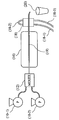
- FIG. 1 is a view schematically showing the overall configuration of a quantum dot manufacturing apparatus according to an embodiment of the present invention.
- FIG. 2 shows a schematic structure of a mixer according to one preferred embodiment of the present invention.
- FIG 3 shows a schematic structure of a mixer according to another preferred embodiment of the present invention.
- FIG. 4 shows a schematic configuration of a quantum dot manufacturing apparatus according to another embodiment of the present invention.
- FIG. 5 shows a schematic configuration of a quantum dot manufacturing apparatus according to another embodiment of the present invention.
- 6 and 7 are experimental results of the quantum dot size according to the temperature change of the first heating furnace and the second heating furnace using the equipment according to FIG. 4.
- the quantum dot manufacturing apparatus includes pumps (10-1, 10-2) for injecting each of a plurality of precursor solutions in which different precursors are dissolved at a uniform flow rate and a constant rate, and two precursor solutions A mixer 12, each of which is uniformly mixed, and a heating furnace 16 in which nuclei are generated and grow as they are heated while passing the mixed precursor solution.
- Precursor solutions in this embodiment are currently commercially available Cd precursor solutions and Se precursor solutions.
- Cd precursor solution is dissolved in cadmium salt (Cadmium salt), squalene (Squalane) and oleic acid in an inert atmosphere such as nitrogen at 150 °C in a three-necked flask, and then reacted for 90 minutes at 100 °C in a vacuum atmosphere cadmium oleate (cadmium oleate) is formed, and after removing impurities such as water, oleylamine is added to the precursor cooled to room temperature.
- Se precursor solution dms Dissolve selenium shot (Selenium shot) in TOP (Tri-n-octylphosphine) to make a TOP Se solution, diluted with Squalane (Squalane) to prepare.
- the two precursor solutions thus made are supplied to the mixer 12 through pumps 10-1 and 10-2, respectively.
- the pumps 10-1 and 10-2 are flow pumps that supply at a uniform flow rate.
- the pumping speed of the flow pump is usually in the range of 0.01-1000 ml / min.
- the two precursor solutions may be supplied by separate, independent pumps, or by a single flow pump having a plurality of channels connected to one drive source to supply the same flow rates. Both precursor solutions may be supplied at the same flow rate or at different flow rates.
- the quantum dot size or characteristics may vary.
- the mixing ratio of the two precursor solutions affects the size of the quantum dots formed.
- the mixing ratio of the Cd precursor solution and the Se precursor solution is usually in the range of 2: 1 to 1:30.
- FIG. 2 shows a schematic structure of a mixer 12 according to a preferred embodiment of the present invention.
- the mixer shown is branched into a plurality of fine paths at each of the two input ports 12-2 and 12-4 into which each of the two precursor solutions is introduced (12-1), with each branched fine path being at the other input port. After separately meeting with the branched minute path (12-3), they are all gathered (12-5) to form a structure that is output to the output port 12-6.
- each branched micro tubing preferably has a diameter or width ranging from several microns to several tens of microns, for example 2.5 ⁇ m.
- the micro tubing meets the micro tubing branched from the other input port (12-3).
- a micro stream of one precursor solution is mixed with a micro stream of another precursor solution.
- the micro tubings are manufactured in a twisted shape immediately before the mixing zone so that the solution forms turbulence near the mixing zone 12-3 to sufficiently promote mixing. It is also important to keep the angle between the two microtubes small enough to maximize the cross-sectional area of the area where they meet.
- These streams may be constructed by connecting independent pipes, which are physically separated from each other, and may also be manufactured in the mixer to be divided into several streams and mixed in one pipe.
- the single tubing encountered in the mixing zone is collected into the output port 12-6 (collection zone, 12-5). Since precursor solutions have already been sufficiently uniformly mixed in the mixing region 12-3, no special structure is required in the collecting region 12-5.
- piping' is to be interpreted to encompass not only general tubular piping but also general structures that restrict the flow of fluid, for example, a pattern made by patterning and joining opposite sides of two metal plates. do.
- the mixer having the same structure as the embodiment shown in FIG. 2 is more advantageous for the mixer having the same structure as the embodiment shown in FIG. 2 to be manufactured by patterning such a metal plate rather than the general cylindrical pipe.
- FIG. 3 shows a schematic structure of a mixer 12 according to another preferred embodiment of the present invention.
- the solution introduced at each of the two input ports 13-1 and 13-3 into which each of the two precursor solutions is introduced is dotted with a plurality of through holes 13-2, one for convenience of illustration.
- the fine streams are maintained at a constant distance even after passing through branch pipes 13-4 and 13-6 under the influence of pressurization by pumping.
- the length d of the mixing portion 13-8 is set sufficiently narrow in consideration of the pressure of the pumping and the like.
- the streams mixed in the mixing section 13-8 are collected on the way to the output port 13-7. Since the direction of gravity varies depending on the direction in which the mixer 12 is placed, the region to be collected may vary.
- the output ports 13-7 must have a suitable diameter to match the flow rates from the two input ports so that they can be mixed in a stream in the mixing section 13-8.
- the pumped mixed solution is mixed in a fine stream so that uniform mixing is possible.
- the pipe 19 connected to the output port 12-6 of the mixer is a pipe having extremely good thermal conductivity such as copper, and passes through the heating furnace 16 and the cooling unit 18. Although the pipe 19 is shown in a straight line in the figure, it may be wound in a spiral or other curved shape to increase the effect of heating or cooling. Quantum dot nuclei are generated in the mixed precursor solution through the heating furnace 16, and the generated nuclei are grown to produce quantum dots.
- a mixer heating unit for heating the micromixer to a constant temperature may be further provided around the micromixer.
- the mixer heating unit is implemented by a hot wire embedded in the mixer 12. This results in substantially two heating parts.
- the mixer heating section is heated to a first temperature region suitable for nucleation.
- the furnace 16 is heated to a second temperature zone suitable for nucleus growth.
- the mixer heating section is maintained at a higher temperature than the heating furnace 16.
- the length of the heating section 16 is much longer than that of the mixer heating section.
- the mixer heating portion is maintained at a higher temperature than the heating furnace 16 when synthesizing a small particle size and the temperature of the mixer heating portion is relatively low when synthesizing a large particle size quantum dot.
- the heating temperature of the preferred mixer heating section is in the range from 170 to 380 ° C.
- the heating temperature of the preferred furnace 16 is in the range of 260-350 ° C.
- the mixer heating section is set to this high temperature and shortens the length. The mixed precursor solution is thus exposed for a short time at high temperature. Since nucleation takes place for shorter moments, it is advantageous to achieve a uniform particle size.
- the furnace 16 is set at a relatively low temperature and has a long length.
- the quantum dot nuclei generated in the mixer heating section generate nuclei in solution in the heating furnace 16 and grow by remaining residual precursors.
- the exposure time in the furnace 16 is related to the average particle diameter of the quantum dots produced.
- the quantum dot manufacturing apparatus may further include a buffer for passing the solution at a relatively low temperature between the mixer heating portion and the furnace (16).
- the buffer is implemented in a section in which the piping 19 is exposed to air between the mixer 12 and the heating furnace 16. In this section, the precursor solutions in the tubing 19 are exposed to room temperature, thereby substantially stopping nucleation. Nucleation and nuclear growth are more clearly divided by the presence of the buffer.
- the buffer is not limited to the example shown and may be a lower temperature furnace or vice versa.
- the cooling unit 18 is water-cooled in which circulating water is supplied to the water jacket through the pipes 18-1, 18-2, and 18-3.
- the present invention is not limited thereto, and various methods such as air cooling are possible.
- the solution containing the completed quantum dots is discharged to the vessel (20).
- the quantum dot manufacturing apparatus includes pumps (10-1, 10-2) for injecting each of a plurality of precursor solutions in which different precursors are dissolved at a uniform flow rate and a constant rate, and two precursor solutions A mixer 12, each of which is mixed uniformly, a first heating portion 14 that generates a plurality of quantum dot nuclei by heating to a first temperature during passage of the mixed precursor solution, and a first temperature during passage of the solution And a second heating portion 16 for growing the nuclei generated by heating to a lower second temperature by the remaining precursors of the solution.
- the two heating units 14 and 16 may be implemented as separate furnaces, or two heating regions independently adjustable in temperature in one furnace. For example, it is a single furnace (furnace) in appearance, but can be seen as two heating units when using two separate sets of heating wire.
- Precursor solutions in this embodiment are currently commercially available Cd precursor solutions and Se precursor solutions.
- Cd precursor solution is dissolved in cadmium salt (Cadmium salt), squalene (Squalane) and oleic acid in an inert atmosphere such as nitrogen at 150 °C in a three-necked flask, and then reacted for 90 minutes at 100 °C in a vacuum atmosphere cadmium oleate (cadmium olete) is formed, and after removing impurities such as water, oleimamine is added to the precursor cooled to room temperature to complete.
- Se precursor solution dms Dissolve selenium shot (Selenium shot) in TOP (Tri-n-octylphosphine) to make a TOP Se solution, diluted with Squalane (Squalane) to prepare.
- the two precursor solutions thus made are supplied to the mixer 12 through pumps 10-1 and 10-2, respectively.
- the pumps 10-1 and 10-2 are flow pumps that supply at a uniform flow rate.
- the pumping speed of the flow pump is usually in the range of 0.01-1000 ml / min. It is also possible to use a pump having a flow rate above this range.
- the two precursor solutions may be supplied by separate, independent pumps, or by a single flow pump having a plurality of channels connected to one drive source to supply the same flow rates. Both precursor solutions may be supplied at the same flow rate or at different flow rates.
- the quantum dot size or characteristics may vary.
- the mixing ratio of the two precursor solutions affects the size of the quantum dots formed.
- the mixing ratio of the Cd precursor solution and the Se precursor solution is usually in the range of 2: 1 to 1:30.
- the mixer 12 has a configuration similar to that shown in FIG. 2 or 3.
- the pipe 19 connected to the output port 12-6 of the mixer is a pipe having extremely good thermal conductivity such as copper, and crosses the first heating part 14, the second heating part 16, and the cooling part 18. Passing by.
- the pipe 19 is shown in a straight line in the figure, it may be wound in a spiral or other curved shape to increase the effect of heating or cooling.
- the first heating portion 14 and the second heating portion 16 have the same width but the second heating portion 16 is much longer in length.
- the first heating unit 14 is maintained at a higher temperature than the second heating unit 16 when synthesizing the small particle size, and the temperature of the first heating unit is relatively low when synthesizing the large particle size. It is advantageous.
- the heating temperature of the first preferred heating portion 14 is in the range of 170 to 380 ° C.
- Preferred heating temperature of the second heating section 16 is in the range of 260 ⁇ 350 °C.
- the present inventors have endeavored to maximally separate quantum dot nucleation and quantum dot nucleus growth.
- Quantum dot nucleation requires higher temperatures than quantum dot nucleus growth.
- the first heating portion 14 is set at this high temperature and makes the length short.
- the mixed precursor solution is thus exposed for a short time at high temperature. Since nucleation takes place for a shorter time, it is advantageous to achieve a uniform particle size.
- the second heating section 16 is set at a relatively low temperature and has a long length.
- the quantum dot nuclei generated in the first heating part 14 generate nuclei in the solution in the second heating part 16 and grow by remaining residual precursors.
- the exposure time in the second heating part 16 is related to the average particle diameter of the quantum dots produced.
- the quantum dot manufacturing apparatus is cooled to a third temperature lower than the first temperature and the second temperature between the first heating portion 14 and the second heating portion 16. It further comprises a buffer 17 for passing the solution at a temperature.
- the buffer 17 is implemented as a section in which the pipe 19 is exposed to air between the two heating units 14 and 16. In this section, the precursor solutions in the tubing 19 are exposed to room temperature, thereby substantially stopping nucleation. Nucleation and nuclear growth are more clearly divided by the presence of the buffer 17.
- the buffer 17 is not limited to the illustrated example, but may be a lower temperature furnace or vice versa.
- the quantum dots grown to the size required by the second heating unit are completely stopped by the nucleus growth while passing through the cooling unit 18.
- the cooling unit 18 is water-cooled in which circulating water is supplied to the water jacket through the pipes 18-1, 18-2, and 18-3.
- the present invention is not limited thereto, and various methods such as air cooling are possible.
- the solution containing the completed quantum dots is discharged to the vessel (20).
- the quantum dot manufacturing apparatus further includes a mixer heating portion 14 'surrounding the mixer to heat the mixer to a constant temperature.
- the mixer heating portion 14 ' is the same heating furnace as the first heating furnace 14', and the mixer 12 is located in the first heating furnace 14 '.
- the mixer heating unit may be a heating furnace provided separately from the first heating furnace.
- the mixer heating unit may be implemented by a heating wire embedded in the mixer.
- the mixer since the mixer is maintained at a high temperature inside the furnace 14 ', a relatively constant time is maintained from the moment when the two precursor solutions are mixed to the moment when the nucleation starts from the moment of leaving the furnace 14'. Uniformity of the particle diameter of the nucleus is improved.
- the method of manufacturing a quantum dot according to the present invention includes a pumping step of pumping and supplying each of a plurality of precursor solutions in which different precursors are dissolved, a mixing step in which respective precursor solutions are uniformly mixed, and a mixed precursor solution is passed through a heating furnace.
- a nucleus is made and includes a heating step that gradually grows.
- the heating step comprises a nucleation step of heating to a first temperature during the passage of the mixed precursor solution to produce a plurality of quantum dot nuclei, and a different temperature from the first temperature during the passage of the solution. And a nucleus growth step of growing nuclei generated by heating to 2 temperatures by the remaining precursors of the solution.
- the first temperature of the nucleation step is higher than the second temperature of the nucleation step, and the nucleation step is shorter in time than the nucleation step.
- the method may further include a buffering step of passing the solution at a temperature cooled to a third temperature lower than a first temperature and a second temperature between the nucleation step and the nuclear growth step.
- the mixing step may be performed while heated to a constant temperature.
- the mixture may further include a buffering step of passing a relatively low temperature while passing through the precursor solution mixed between the mixing step and the heating step.
- 6 and 7 are experimental results of the quantum dot size according to the temperature change of the first heating furnace and the second heating furnace using the equipment according to FIG. 4.
- the particle size of quantum dots is closely related to the emission wavelength band.
- the quantum dots emitting light at 600 nm when the temperatures of the first and second heating furnaces are 170 ° C and 380 ° C are 580 when 170 ° C and 360 ° C.
- Quantum dots luminescent at 550 nm at 380 ° C. and 300 ° C. and at 520 nm at 380 ° C.
Landscapes
- Chemical & Material Sciences (AREA)
- Engineering & Computer Science (AREA)
- Nanotechnology (AREA)
- Crystallography & Structural Chemistry (AREA)
- General Physics & Mathematics (AREA)
- Physics & Mathematics (AREA)
- Condensed Matter Physics & Semiconductors (AREA)
- Materials Engineering (AREA)
- Manufacturing & Machinery (AREA)
- Composite Materials (AREA)
- Inorganic Chemistry (AREA)
- Organic Chemistry (AREA)
- Led Device Packages (AREA)
- Liquid Deposition Of Substances Of Which Semiconductor Devices Are Composed (AREA)
Abstract
본 발명은 나노 크기의 반도체성 결정인 양자점 제조 기술에 관련된다. 양자점 제조 장치는 전구체 용액을 혼합하되, 복수의 전구체 용액이 하나의 채널에서 혼합될 때 서로 다른 용액이 미세하게 상호 혼합될 수 있도록 다수의 미세한 용액으로 나뉘어져 혼합되는 믹서와, 이 믹서에서 출력되는 혼합된 용액이 통과하면서 핵이 생성되고 성장하여 양자점이 형성되는 가열부를 포함한다. 이 믹서에는 온도를 조절할 수 있는 가열 장치가 추가될 수 있다. 또한 믹서와 가열로 사이에는 낮은 온도로 추가적인 핵 생성을 차단하는 버퍼가 구비될 수 있다. 이에 의해 매우 큰 유량과 유속에서 양자점을 제조할 수 있어 양자점의 대량 생산이 가능하게 된다.
Description
본 발명은 나노 크기의 반도체성 결정인 양자점 제조 기술에 관련된다.
양자점(quantum dot)은 벌크 상태에서 반도체성 물질이 가지고 있지 않은 특별한 광학적/전기적 특성을 나타낸다. 나노 양자점은 이 같은 특성을 이용하여 차세대 고휘도 LED, 바이오센서, 레이저, 태양전지 나노 소재 등으로 주목받고 있다.
종래 이러한 양자점은 주로 실험실에서 고온의 용매에 차가운 전구체를 빠르게 주입시켜 핵을 생성하고, 온도를 가하여 성장시키는 방법으로 생산해왔다. 그러나 반응의 제어가 되지 않아 원하는 입자의 크기를 조절할 수 없고 반응량에 따라 조건이 달라져 균일성 확보를 위한 후공정의 손실 등으로 인해 극히 소량을 생산하는데 그치고 있다. 양자점의 경우 입자의 크기는 광학적/전기적인 특성에 직접적으로 영향을 미치므로, 입경의 균일성은 곧 양자점의 품질을 의미하고, 그 균일성이 일정 이하이면 양자점으로서의 특성을 잃게 되어 상업적으로 의미가 없게 된다.
미국특허 6,682,596호에는 전구체와 용매를 섞은 후 일정한 속도로 고온의 열전도성 튜브에 흘려서 양자점을 생산하는 방법을 개시하고 있다. 그러나 이 방법에 의해서도 소량생산일 경우 입경의 균일성은 우수하지만 가는 튜브에서의 혼합 단계에서의 불안정성으로 인해 생산량이 극히 소량에 그치는 문제점을 여전히 가지고 있다.
본 발명은 이 같은 문제점을 해결하고자 하는 것으로, 양자점을 종래에 비해 훨씬 대량으로 생산할 수 있는 제조 장치 및 방법을 제공하는 것을 목적으로 한다.
나아가 본 발명은 입경이 균일하고 수율이 높으면서도 대량으로 양자점을 생산할 수 있는 제조 장치 및 방법을 제공하는 것을 목적으로 한다.
상기 목적을 달성하기 위한 본 발명의 일 양상에 따른 양자점 제조 장치는 복수의 전구체 용액 각각이 유입되는 복수의 입력포트 각각에서 다수의 미세한 경로로 분기되고, 각각의 분기된 미세한 경로가 타 입력포트에서 분기된 미세한 경로와 만난 후, 이들이 모두 취합되어 출력포트로 출력되는 마이크로 믹서를 통해 복수의 전구체 용액이 혼합되는 것을 특징으로 한다.
전구체의 혼합 비율은 입자의 직경에 영향을 미친다. 전구체 용액이 급격히 혼합될 경우 국부적으로 혼합 비율은 변동하고, 이에 따라 불규칙한 반응으로 인해 입경의 균일성이 악화된다. 실험실에서 이루어지는 일반적인 양자점 제조 공정이나 미국특허 6,682,596호의 공정에서 대량으로 양자점을 생산하지 못하는 이유 중 하나가 여기에 있다.
즉, 본 발명에 따른 믹서를 거치게 되면 용액이 흐르는 관안에서 어느 위치에서든지 매우 균일하게 섞이게 되고, 이는 균일한 핵생성을 유도하게 된다. 이는 기존의 미국특허 6,682,596에서 관의 직경이 커질수록 관안에서의 혼합의 균일성을 확보하기 어렵기 때문에 많은 양을 만들 수 없는 문제를 해결할 수 있게 된다. 이는 마치 이 종래기술에서 채택하는 유사한 크기의 관 수십 내지 수백개를 통해 혼합하는 것과 유사하다. 따라서 본 발명의 믹서를 채택함에 따라 양자점의 대량생산이 가능하게 된다.
본 발명은 복수의 전구체 용액 각각이 미세한 스트림으로 분기되고, 이 분기된 상태에서 미세한 용량의 전구체 용액들이 혼합되고, 혼합된 스트림들이 취합되므로, 각각의 미세한 스트림들은 균일한 비율로 혼합이 가능하고, 또 이들을 취합함에 의해 한번에 대량 생산이 가능하게 된다.
본 발명의 또다른 양상에 따르면, 전구체 용액들을 혼합하는 믹서는 가열된다. 이때 가열되는 온도는 양자점 생성 온도 범위인 것이 바람직하다.
믹서를 상온에 유지하여도 혼합하는 과정에서 일부 양자점 핵들이 생성된다. 이는 전체적인 입자의 직경의 균일성에 악영향을 미친다. 본 발명은 믹서가 가열로 내부에 위치함으로써 최대한 핵 생성되는 시간 간격을 짧고 일정하게 유지하여 입자의 직경의 균일성을 한층 개선한다.
본 발명의 또다른 양상에 따른 양자점 제조 장치는 가열되는 믹서와 가열로 사이에 상대적으로 낮은 온도에서 용액을 통과시키는 버퍼를 더 구비한다.
이 같은 버퍼에 의해 양자점의 핵 생성 과정은 확실히 중단되고, 따라서 핵 생성 과정과 핵 성장 과정은 좀 더 명확히 구분되어 제조된 양자점의 입자의 크기의 균일성이 한층 더 개선된다.
본 발명의 또다른 양상에 따른 양자점 제조 장치는 혼합된 전구체 용액을 제 1 온도로 가열된 제 1 가열부와, 제 1 온도보다 낮은 제 2 온도로 가열된 제 2 가열부를 통해 순차적으로 가열하는 것을 특징으로 한다.
단일의 가열로를 사용하는 양자점 제조 장치의 경우 양자점 핵 생성과 성장이 동시에 진행되면서, 먼저 생긴 핵과 나중에 생긴 핵이 존재하게 되고 결국은 핵성장이 진행되고 나면 크기가 다른 양자점들이 생기게 되어 입자의 크기가 불균일해진다.
일반적으로 양자점의 핵 생성 온도와 핵 성장 온도는 일부 겹치지만 핵 생성 온도 대역이 핵 성장 온도 대역에 높은 범위에 걸친다. 본 발명은 제 1 온도에서 핵 생성이 일어나고, 제 2 온도에서 생성된 핵이 성장하면서 핵 생성과 핵 성장이 어느 정도 분리되어 제조된 양자점의 입자의 크기의 균일성이 개선된다.
본 발명의 또다른 양상에 따른 양자점 제조 장치는 제 1 가열부와 제 2 가열부 사이에 제 1 온도 및 제 2 온도보다 낮은 제 3 온도로 식힌 온도에서 용액을 통과시키는 버퍼를 더 구비한다.
이 같은 버퍼에 의해 양자점의 핵 생성 과정은 확실히 중단되고, 따라서 핵 생성 과정과 핵 성장 과정은 좀 더 명확히 구분되어 제조된 양자점의 입자의 크기의 균일성이 한층 더 개선된다.
또 본 발명은 전구체 용액을 혼합할 때 미세한 스트림으로 분기시킨 상태에서 혼합한 후 취합하는 방식을 취함으로써 대량의 용액이 소량과 마찬가지로 균일하게 혼합되어 결과적으로 양자점 생산량을 늘일 수 있다.
본 발명은 양자점의 핵 생성과정과 핵 성장 과정을 분리시켜 입자의 직경이 균일하여 양자점 제조 방법의 수율을 높일 수 있다.
도 1은 본 발명의 바람직한 일 실시예에 따른 양자점 제조 장치의 전체적인 구성을 대략적으로 도시한 도면이다.
도 2는 본 발명의 바람직한 일 실시예에 따른 믹서의 개략적인 구조를 도시한다.
도 3는 본 발명의 또다른 바람직한 일 실시예에 따른 믹서의 개략적인 구조를 도시한다.
도 4은 본 발명의 또다른 실시예에 따른 양자점 제조 장치의 개략적인 구성을 도시한다.
도 5는 본 발명의 또다른 실시예에 따른 양자점 제조 장치의 개략적인 구성을 도시한다.
도 6 및 도 7은 도 4에 따른 장비를 사용하여 제 1 가열로 및 제 2 가열로의 온도 변화에 따른 양자점 크기의 실험 결과이다.
전술한 그리고 추가적인 본 발명의 양상들은 후술하는 실시예들을 통해 보다 명백해질 것이다. 이하에서는 이 같은 본 발명의 양상들을 첨부된 도면을 참조하여 기술되는 바람직한 실시예들을 통해 당업자라면 누구나 용이하게 이해하고 재현할 수 있을 정도로 상세히 설명한다.
도 1은 본 발명의 바람직한 일 실시예에 따른 양자점 제조 장치의 전체적인 구성을 대략적으로 도시한 도면이다. 도시된 바와 같이, 일 실시예에 따른 양자점 제조 장치는 상이한 전구체가 용해된 복수의 전구체 용액 각각을 균일한 유량과 일정한 속도로 주입하는 펌프들(10-1, 10-2)과, 두 전구체 용액 각각이 균일하게 혼합되는 믹서(12)와, 혼합된 전구체 용액이 통과하는 동안 가열되면서 핵이 생성되고 성장하는 가열로(16)를 포함한다.
본 실시예에 있어서 전구체(precursor) 용액들은 현재 상업적으로 활용도가 높은 Cd 전구체 용액 및 Se 전구체 용액이다. Cd 전구체 용액은 3구 플라스크에 카드뮴 염(Cadmium salt)과 스쿠알렌(Squalane) 및 올레산(Oleic acid)을 질소등 불활성 분위기하에 150℃에서 용해시킨 후, 진공분위기 100℃에서 90분간 반응시켜 카드뮴 올레산염(cadmium oleate)를 형성시키고, 수분 등 불순물을 제거한 후 상온으로 냉각시킨 전구체에 올레일라민(Oleylamine)을 넣어 완성한다. Se 전구체 용액dms TOP(Tri-n-octylphosphine) 에 셀레늄 샷(Selenium shot)을 용해시켜 TOP Se 용액을 만들고 스쿠알렌(Squalane)으로 희석시켜 준비한다.
이렇게 만들어진 두 전구체 용액은 각각 펌프(10-1, 10-2)를 통해 믹서(12)로 공급한다. 펌프(10-1,10-2)는 균일한 유량으로 공급하는 유량 펌프이다. 유량 펌프의 펌핑 속도는 통상 0.01~1000 ml/min 범위이다. 두 전구체 용액은 독립적인 별도의 펌프로 공급될 수도 있고, 하나의 구동원에 연결되어 동일한 유량을 공급하는 복수의 채널을 구비한 단일의 유량 펌프를 통해 공급될 수도 있다. 두 전구체 용액은 동일한 유량으로 공급될 수도 있고 상이한 유량으로 공급될 수도 있다. 전구체 비율에 따라 양자점 크기나 특성이 달라질 수 있다. 본 발명에 있어서 두 전구체 용액의 혼합 비율은 형성되는 양자점의 크기에 영향을 미친다. Cd 전구체 용액 및 Se 전구체 용액의 혼합 비율은 통상 2:1~1:30의 범위이다.
도 2는 본 발명의 바람직한 일 실시예에 따른 믹서(12)의 개략적인 구조를 도시한다. 그러나 본 발명이 반드시 이러한 종류의 믹서로 제한되는 것은 아니다. 도시된 믹서는 두 전구체 용액 각각이 유입되는 두개의 입력포트(12-2, 12-4) 각각에서 다수의 미세한 경로로 분기되고(12-1), 각각의 분기된 미세한 경로가 타 입력포트에서 분기된 미세한 경로와 개별적으로 만난 후(12-3), 이들이 모두 취합되어(12-5) 출력포트(12-6)로 출력되는 구조로 형성된다.
입력 포트(12-2,12-4)를 지난 배관은 모두 유체역학적으로 동일한 특성을 가지는 다수의 경로로 분기된다(12-1). 따라서 입력포트에 유입된 전구체 용액은 동일한 유량을 가지는 다수의 스트림으로 나누어진다. 각 분기된 마이크로 배관들은 직경 혹은 폭이 수 내지 수십 마이크론, 예를 들어 2.5μm 정도의 크기를 가지는 것이 바람직하다. 마이크로 배관들은 타 입력포트에서 분기된 마이크로 배관과 만난다(12-3). 이 부분에서 한 전구체 용액의 마이크로 스트림이 타 전구체 용액의 마이크로 스트림과 혼합된다. 특히 혼합 영역(12-3) 부근에서 용액이 난류(turbulence)를 형성하여 혼합이 충분히 촉진되도록 마이크로 배관들은 혼합 영역 직전에서 뒤틀어지는 형태로 제작되는 것이 바람직하다. 두 마이크로 배관이 만나는 각도를 충분히 작게 유지하여 만나는 영역의 단면적을 최대로 확보하는 것도 중요하다.
이러한 스트림은 각각 물리적으로 떨어져 있는 독립적인 배관들을 연결하여 구성할 수도 있으며, 또한 하나의 배관안에서 여러 스트림으로 나뉘어 혼합되도록 믹서내부의 구조를 제작할 수 있다.
혼합 영역에서 만난 단일의 배관은 출력 포트(12-6)로 취합된다(취합 영역, 12-5). 이미 전구체 용액들이 혼합 영역(12-3)에서 충분히 균일하게 섞였기 때문에 취합 영역(12-5)에서는 그리 특별한 구조가 요구되지 않는다.
본 명세서에서 '배관'이라는 용어는 일반적인 관 형태의 배관 뿐 아니라 유체의 흐름을 제한하는 일반적인 구조체, 예를 들면 두 금속판의 마주보는 면을 패터닝하고 이들을 합착하여 만드는 형태와 같은 일반적인 구성을 포괄하도록 해석된다.
도 2에 제시된 실시예와 같은 구조의 믹서는 마이크로 배관이 일반적인 원통 배관보다는 이 같은 금속판의 패터닝을 통해 제작하는 것이 더 유리하다.
도 3는 본 발명의 또다른 바람직한 일 실시예에 따른 믹서(12)의 개략적인 구조를 도시한다. 도시된 믹서는 두 전구체 용액 각각이 유입되는 두개의 입력포트(13-1, 13-3) 각각에서 유입된 용액은 다수의 관통홀(13-2, 도시의 편의를 위해 하나에 대해서만 점선 도시함)이 천공된 분기관(13-4)을 통해 미세한 스트림으로 나누어지고, 이 미세한 스트림들이 타측 분기관(13-6)의 대응되는 스트림들과 혼합부(13-8)에서 부딪히면서 혼합된다. 미세한 스트림들은 펌핑에 의한 가압의 영향으로 분기관(13-4, 13-6)을 통과한 후에도 일정한 거리까지 스트림이 유지된다. 혼합부(13-8)의 길이(d)는 펌핑의 압력 등을 고려하여 충분히 좁게 설정된다.
혼합부(13-8)에서 혼합된 스트림들은 출력 포트(13-7)로 가는 도중에 취합된다. 믹서(12)가 놓여지는 방향에 따라 중력 방향이 달라지므로 취합되는 영역이 달라질 수 있다. 출력 포트(13-7)는 혼합부(13-8)에서 스트림 상태로 혼합되어질 수 있도록 두 입력 포트로부터의 유량에 맞추어 적절한 직경을 가져야 한다.
펌핑되어 유입되는 혼합 용액들이 미세한 스트림 상태에서 혼합되기 때문에 균일한 혼합이 가능하게 된다.
믹서의 출력 포트(12-6)에 연결된 배관(19)은 구리와 같은 열전도성이 극히 양호한 배관으로, 가열로(16), 냉각부(18)를 가로질러 지나간다. 도면에서 이 배관(19)은 직선으로 도시되었으나, 가열 혹은 냉각의 효과를 높이기 위해 나선형으로 감기거나 다른 곡선 형태로 될 수도 있다. 가열로(16)를 거치면서 혼합된 전구체 용액에서는 양자점 핵이 생성되고, 생성된 핵이 성장하여 양자점이 생산된다.
본 발명의 또다른 양상에 따라, 마이크로 믹서 주변에 그 마이크로 믹서를 일정한 온도로 가열하는 믹서 가열부가 추가로 구비될 수 있다. 도시된 실시예에 있어서 믹서 가열부는 믹서(12) 내에 내장된 열선으로 구현된다. 이에 의해 실질적으로 두 개의 가열부가 존재하게 된다. 믹서 가열부는 핵 생성에 적합한 제 1 온도 영역으로 가열된다. 가열로(16)는 핵 성장에 적합한 제 2 온도 영역으로 가열된다. 믹서 가열부는 가열로(16)보다 더 고온으로 유지된다.
이 경우 믹서가열부에 비해 가열로(16)는 가열 구간의 길이가 훨씬 길다. 또한 작은 입경의 양자점을 합성하고자 할 때 믹서 가열부는 가열로(16)보다 더 고온으로 유지되고 큰 입경의 양자점을 합성하고자 할 때 믹서 가열부의 온도는 상대적으로 낮은 것이 유리하다. 바람직한 믹서 가열부의 가열온도는 170 ~ 380℃ 범위이다. 바람직한 가열로(16)의 가열온도는 260 ~ 350 ℃ 범위이다.
본 발명자들은 종래 방법에 있어서 양자점 핵의 성장 중에 양자점 핵 생성이 계속 일어나면서 각 핵들이 성장하는 시간이 달라지고 이것이 제조되는 양자점의 입경이 불균일한 주된 원인이라는 사실을 알아냈다. 이에 따라 본 발명자들은 양자점 핵 생성과 양자점 핵 성장을 최대한 분리시키기 위해 노력했다. 양자점 핵 생성은 양자점 핵 성장에 비해 높은 온도가 요구된다. 믹서 가열부는 이 높은 온도로 설정되고 길이를 짧게 만든다. 이에 따라 혼합된 전구체 용액은 고온에서 짧은 시간동안 노출된다. 핵 생성이 보다 짧은 순간동안 이루어지므로, 균일한 입경을 달성하는데 유리하다. 가열로(16)는 상대적으로 낮은 온도로 설정되고 길이는 길다. 믹서 가열부에서 생성된 양자점 핵들은 가열로(16)에서 용액 중에 핵을 생성하고 남아있는 잔여 전구체들에 의해 성장한다. 가열로(16)에서의 노출 시간은 제조되는 양자점의 평균 입경과 관련된다.
본 발명의 유리한 또다른 양상에 따라, 일 실시예에 따른 양자점 제조 장치는 믹서 가열부와 가열로(16) 사이에 상대적으로 낮은 온도에서 용액을 통과시키는 버퍼를 더 포함할 수 있다. 도시된 실시예에 있어서, 버퍼는 믹서(12)와 가열로(16) 사이에 배관(19)이 공기중에 노출되는 구간으로 구현된다. 이 구간에서 배관(19) 내의 전구체 용액들은 상온에 노출되고 이에 따라 핵 생성이 실질적으로 중단된다. 버퍼의 존재에 의해 핵 생성과 핵 성장은 보다 명확히 나누어진다. 그러나 버퍼는 도시된 예에 한정되는 것은 아니며 보다 저온의 가열로이거나 혹은 반대로 공냉식 혹은 수냉식 냉각기일 수도 있다.
가열로(16)에서 요구되는 크기로 성장한 양자점들은 냉각부(18)를 거치면서 핵 성장이 완전히 중단된다. 도시된 실시예에 있어서 냉각부(18)는 배관(18-1,18-2,18-3)을 통해 물 재킷으로 순환수가 공급되는 수냉식이다. 그러나 이에 한정되지는 않으며, 공냉식 등 다양한 방식이 가능하다. 완성된 양자점들이 포함된 용액은 용기(20)로 배출된다.
도 4은 본 발명의 또다른 바람직한 일 실시예에 따른 양자점 제조 장치의 전체적인 구성을 대략적으로 도시한 도면이다. 도시된 바와 같이, 일 실시예에 따른 양자점 제조 장치는 상이한 전구체가 용해된 복수의 전구체 용액 각각을 균일한 유량과 일정한 속도로 주입하는 펌프들(10-1, 10-2)과, 두 전구체 용액 각각이 균일하게 혼합되는 믹서(12)와, 혼합된 전구체 용액이 통과하는 동안 제 1 온도로 가열하여 다수의 양자점 핵들을 생성하는 제 1 가열부(14)와, 용액이 통과하는 동안 제 1 온도보다 낮은 제 2 온도로 가열하여 생성된 핵들을 용액의 잔여 전구체에 의해 성장시키는 제 2 가열부(16)를 포함한다. 두 개의 가열부(14,16)는 별도의 가열로(furnace)로 구현될 수도 있고, 하나의 가열로에서 독립적으로 온도 조절 가능한 두 개의 가열 영역으로 구현될 수도 있다. 예를 들어 외관적으로 하나의 가열로(furnace)이지만, 독립된 2 조의 열선을 사용할 경우 2개의 가열부로 볼 수 있다.
본 실시예에 있어서 전구체(precursor) 용액들은 현재 상업적으로 활용도가 높은 Cd 전구체 용액 및 Se 전구체 용액이다. Cd 전구체 용액은 3구 플라스크에 카드뮴 염(Cadmium salt)과 스쿠알렌(Squalane) 및 올레산(Oleic acid)을 질소등 불활성 분위기하에 150℃에서 용해시킨 후, 진공분위기 100℃에서 90분간 반응시켜 카드뮴 올레산염(cadmium olete)를 형성시키고, 수분 등 불순물을 제거한 후 상온으로 냉각시킨 전구체에 올레이라민(Oleylamine)을 넣어 완성한다. Se 전구체 용액dms TOP(Tri-n-octylphosphine) 에 셀레늄 샷(Selenium shot)을 용해시켜 TOP Se 용액을 만들고 스쿠알렌(Squalane)으로 희석시켜 준비한다.
이렇게 만들어진 두 전구체 용액은 각각 펌프(10-1, 10-2)를 통해 믹서(12)로 공급한다. 펌프(10-1,10-2)는 균일한 유량으로 공급하는 유량 펌프이다. 유량 펌프의 펌핑 속도는 통상 0.01~ 1000ml/min 범위이다. 또한 이 범위이상의 유량을 가지는 펌프의 사용도 가능하다. 두 전구체 용액은 독립적인 별도의 펌프로 공급될 수도 있고, 하나의 구동원에 연결되어 동일한 유량을 공급하는 복수의 채널을 구비한 단일의 유량 펌프를 통해 공급될 수도 있다. 두 전구체 용액은 동일한 유량으로 공급될 수도 있고 상이한 유량으로 공급될 수도 있다. 전구체 비율에 따라 양자점 크기나 특성이 달라질 수 있다. 본 발명에 있어서 두 전구체 용액의 혼합 비율은 형성되는 양자점의 크기에 영향을 미친다. Cd 전구체 용액 및 Se 전구체 용액의 혼합 비율은 통상 2:1~1:30의 범위이다.
도시된 실시예에 있어서 믹서(12)는 도 2 또는 도 3에 도시된 바와 유사한 구성을 가진다. 믹서의 출력 포트(12-6)에 연결된 배관(19)은 구리와 같은 열전도성이 극히 양호한 배관으로, 제 1 가열부(14), 제 2 가열부(16), 냉각부(18)를 가로질러 지나간다. 도면에서 이 배관(19)은 직선으로 도시되었으나, 가열 혹은 냉각의 효과를 높이기 위해 나선형으로 감기거나 다른 곡선 형태로 될 수도 있다.
제시된 실시예에 있어서, 제 1 가열부(14)와 제 2 가열부(16)는 폭은 동일하지만 길이는 제 2 가열부(16)가 훨씬 길다. 또한 작은 입경의 양자점을 합성하고자 할 때 제 1 가열부(14)는 제 2 가열부(16)보다 더 고온으로 유지되고 큰입경의 양자점을 합성하고자 할 때 제 1가열부의 온도는 상대적으로 낮은 것이 유리하다. 바람직한 제 1 가열부(14)의 가열온도는 170 ~ 380℃ 범위이다. 바람직한 제 2 가열부(16)의 가열온도는 260 ~ 350 ℃ 범위이다.
본 발명자들은 종래 방법에 있어서 양자점 핵의 성장 중에 양자점 핵 생성이 계속 일어나면서 각 핵들이 성장하는 시간이 달라지고 이것이 제조되는 양자점의 입경이 불균일한 주된 원인이라는 사실을 알아냈다. 이에 따라 본 발명자들은 양자점 핵 생성과 양자점 핵 성장을 최대한 분리시키기 위해 노력했다. 양자점 핵 생성은 양자점 핵 성장에 비해 높은 온도가 요구된다. 제 1 가열부(14)는 이 높은 온도로 설정되고 길이를 짧게 만든다. 이에 따라 혼합된 전구체 용액은 고온에서 짧은 시간동안 노출된다. 핵 생성이 보다 짧은 순간동안 이루어지므로, 균일한 입경을 달성하는데 유리하다. 제 2 가열부(16)는 상대적으로 낮은 온도로 설정되고 길이는 길다. 제 1 가열부(14)에서 생성된 양자점 핵들은 제 2 가열부(16)에서 용액 중에 핵을 생성하고 남아있는 잔여 전구체들에 의해 성장한다. 제 2 가열부(16)에서의 노출 시간은 제조되는 양자점의 평균 입경과 관련된다.
본 발명의 유리한 또다른 양상에 따라, 일 실시예에 따른 양자점 제조 장치는 제 1 가열부(14)와 제 2 가열부(16) 사이에 제 1 온도 및 제 2 온도보다 낮은 제 3 온도로 식힌 온도에서 용액을 통과시키는 버퍼(17)를 더 포함한다. 도시된 실시예에 있어서, 버퍼(17)는 두 가열부(14,16) 사이에 배관(19)이 공기중에 노출되는 구간으로 구현된다. 이 구간에서 배관(19) 내의 전구체 용액들은 상온에 노출되고 이에 따라 핵 생성이 실질적으로 중단된다. 버퍼(17)의 존재에 의해 핵 생성과 핵 성장은 보다 명확히 나누어진다. 그러나 버퍼(17)는 도시된 예에 한정되는 것은 아니며 보다 저온의 가열로이거나 혹은 반대로 공냉식 혹은 수냉식 냉각기일 수도 있다.
제 2 가열부에서 요구되는 크기로 성장한 양자점들은 냉각부(18)를 거치면서 핵 성장이 완전히 중단된다. 도시된 실시예에 있어서 냉각부(18)는 배관(18-1,18-2,18-3)을 통해 물 재킷으로 순환수가 공급되는 수냉식이다. 그러나 이에 한정되지는 않으며, 공냉식 등 다양한 방식이 가능하다. 완성된 양자점들이 포함된 용액은 용기(20)로 배출된다.
도 5는 본 발명의 또다른 실시예에 따른 양자점 제조 장치의 개략적인 구성을 도시한다. 도 4과 유사한 구성요소에는 동일한 도면부호로 인용한다. 도시된 바와 같이, 제시된 실시예에 따른 양자점 제조 장치는 믹서를 둘러싸서 믹서를 일정한 온도로 가열하는 믹서 가열부(14')를 더 포함한다. 본 실시예에 있어서, 믹서 가열부(14')는 제 1 가열로(14')와 동일한 가열로이고, 상기 믹서(12)는 제 1 가열로(14') 내에 위치한다. 그러나 본 발명은 이에 한정되지 않으며, 믹서 가열부는 제 1 가열로와 별도로 구비된 가열로일 수 있다. 또다른 예에 있어서 믹서 가열부는 믹서에 내장된 열선으로 구현될 수도 있다.
믹서에서 혼합되는 동안에, 비록 상온일지라도 혼합되는 양자점 핵이 생성될 수 있다. 본 실시예예에서는 믹서가 가열로(14') 내부에서 고온으로 유지되므로, 두 전구체 용액이 혼합되면서부터 핵 생성이 개시되는 순간부터 가열로(14')를 벗어나는 순간까지가 비교적 일정한 시간이 유지되므로 핵의 입경의 균일성이 개선된다.
이하에서는 본 발명의 일 양상에 따른 양자점 제조 방법에 대해 설명한다. 본 발명에 따른 양자점 제조 방법은 상이한 전구체가 용해된 복수의 전구체 용액 각각을 펌핑하여 공급하는 펌핑 단계와, 각각의 전구체 용액들이 균일하게 혼합되는 혼합 단계와, 혼합된 전구체 용액이 가열로를 통과하면서 핵이 만들어지고, 점차적으로 성장시키는 가열 단계를 포함한다.
본 발명의 또다른 양상에 따라, 상기 가열 단계는 혼합된 전구체 용액이 통과하는 동안 제 1 온도로 가열하여 다수의 양자점 핵들을 생성하는 핵 생성단계와, 용액이 통과하는 동안 제 1 온도와 다른 제 2 온도로 가열하여 생성된 핵들을 용액의 잔여 전구체에 의해 성장시키는 핵 성장 단계를 포함할 수 있다. 핵 생성 단계의 제 1 온도는 핵 성장 단계의 제 2 온도보다 높고, 핵 생성단계는 핵 성장단계보다 시간적으로 짧다. 또한 핵 생성단계와 상기 핵 성장 단계 사이에 제 1 온도 및 제 2 온도보다 낮은 제 3 온도로 식힌 온도에서 용액을 통과시키는 버퍼링 단계를 더 포함할 수 있다.
본 발명의 또다른 양상에 따라, 혼합 단계가 일정한 온도로 가열된 상태에서 진행될 수도 있다. 이 경우 혼합 단계 및 가열 단계 사이에 혼합된 전구체 용액들이 통과하면서 상대적으로 저온인 구간을 통과하는 버퍼링 단계를 더 포함할 수 있다.
도 6 및 도 7은 도 4에 따른 장비를 사용하여 제 1 가열로 및 제 2 가열로의 온도 변화에 따른 양자점 크기의 실험 결과이다. 양자점에서 입경의 크기는 발광 파장대와 밀접한 관련이 있다. 유속이 1ml/min 이고, 전구체 비율이 1:1 인 경우 제 1 가열로 및 제 2 가열로의 온도가 170℃, 380℃일 때 600 nm에서 발광하는 양자점을, 170℃, 360℃ 일 때 580 nm에서 발광하는 양자점을, 270℃, 330℃ 일 때 570 nm에서. 380℃, 300℃ 일 때 550 nm, 그리고 380℃, 260℃일 때 520 nm에서 발광하는 양자점이 제조되었다. 도 7은 입경의 균일성을 나타내는 도표이다. 추가 공정 없이 입경 균일도가 매우 높은 양자점 (FWHM 35 nm)이 고 유속 조건 (1ml/min, 실시예) 에서 생성됨을 알 수 있다. 즉, 종래기술과 달리 본 발명에 따른 믹서를 사용함으로써 다양한 범위의 균일한 입경을 가진 양자점이 대량으로 제조되었다.
이상에서 본 발명은 첨부된 도면을 참조하여 기술되는 실시예들을 중심으로 기술되었다. 하지만 본 발명은 이에 한정되는 것은 아니며, 당업자라면 누구나 도출할 수 있는 자명한 변형예들을 포괄하도록 특허청구범위를 통해 의도되었다.
Claims (9)
- 상이한 전구체가 용해된 복수의 전구체 용액 각각을 유량으로 공급하는 적어도 하나의 펌프와;상기 복수의 전구체 용액 각각이 유입되는 복수의 입력포트 각각에서 다수의 미세한 경로로 분기되고, 각각의 분기된 미세한 경로가 타 입력포트에서 분기된 미세한 경로와 만난 후, 이들이 모두 취합되어 출력포트로 출력되는 마이크로 믹서와;상기 출력포트에서 출력되는 혼합된 용액이 통과하면서 핵이 생성되고 성장하여 양자점이 형성되는 가열부;를 포함하는 양자점 제조 장치.
- 제 1 항에 있어서, 상기 양자점 제조 장치가 :상기 마이크로 믹서 주변에 그 마이크로 믹서를 일정한 온도로 가열하는 믹서 가열부;를 더 포함하는 양자점 제조 장치.
- 제 2 항에 있어서, 상기 양자점 제조 장치가 상기 믹서 가열부와 상기 가열부 사이에 상대적으로 저온인 버퍼를 더 포함하는 양자점 제조 장치.
- 제 2 항에 있어서, 상기 믹서 가열부는 상기 가열부와 일체로 형성되어 상기 마이크로 믹서가 상기 가열부 내에 위치하는 양자점 제조 장치.
- 제 1 항 내지 제 4 항 중의 어느 한 항에 있어서, 상기 양자점 제조 장치가 :상기 가열부에서 출력되는 용액을 급격히 식히는 냉각부;를 더 포함하는 것을 특징으로 하는 양자점 제조 장치.
- 상이한 전구체가 용해된 복수의 전구체 용액 각각을 균일한 유량과 일정한 속도로 펌핑하여 공급하는 펌핑 단계와;각각의 전구체 용액들이 다수의 미세한 흐름으로 분할된 후, 이 분할된 흐름들이 타 전구체 용액의 분할된 미세한 흐름과 개별적으로 혼합되고, 혼합된 용액들이 다시 취합되는 혼합 단계와;혼합된 용액을 일정한 온도로 가열하여 핵을 생성하고 성장시키는 가열 단계;를 포함하는 양자점 제조 방법.
- 제 6 항에 있어서,상기 혼합 단계가 일정한 온도로 가열된 상태에서 진행되는 양자점 제조 방법.
- 제 7 항에 있어서, 상기 혼합 단계 및 가열 단계 사이에 혼합된 전구체 용액들이 통과하면서 상대적으로 저온인 구간을 통과하는 버퍼링 단계;를 더 포함하는 양자점 제조 방법.
- 제 6 항 또는 제 8 항 중의 어느 한 항에 있어서, 상기 양자점 제조 장법이 상기 가열 단계 이후에 :용액을 급격히 식히는 냉각 단계;를 더 포함하는 양자점 제조 방법.
Priority Applications (3)
| Application Number | Priority Date | Filing Date | Title |
|---|---|---|---|
| EP09823807.4A EP2351702B1 (en) | 2008-10-27 | 2009-10-27 | Apparatus and method for manufacturing quantum dot |
| CN2009801483497A CN102232056B (zh) | 2008-10-27 | 2009-10-27 | 用于生成量子点的装置和方法 |
| US13/126,053 US8354090B2 (en) | 2008-10-27 | 2009-10-27 | Apparatus and method for manufacturing quantum dot |
Applications Claiming Priority (2)
| Application Number | Priority Date | Filing Date | Title |
|---|---|---|---|
| KR10-2008-0105369 | 2008-10-27 | ||
| KR1020080105369A KR101078050B1 (ko) | 2008-10-27 | 2008-10-27 | 양자점 제조 장치 및 양자점 제조 방법 |
Publications (2)
| Publication Number | Publication Date |
|---|---|
| WO2010050727A2 true WO2010050727A2 (ko) | 2010-05-06 |
| WO2010050727A3 WO2010050727A3 (ko) | 2010-07-29 |
Family
ID=42129448
Family Applications (1)
| Application Number | Title | Priority Date | Filing Date |
|---|---|---|---|
| PCT/KR2009/006228 Ceased WO2010050727A2 (ko) | 2008-10-27 | 2009-10-27 | 양자점 제조 장치 및 양자점 제조 방법 |
Country Status (6)
| Country | Link |
|---|---|
| US (1) | US8354090B2 (ko) |
| EP (1) | EP2351702B1 (ko) |
| KR (1) | KR101078050B1 (ko) |
| CN (1) | CN102232056B (ko) |
| TW (1) | TWI460324B (ko) |
| WO (1) | WO2010050727A2 (ko) |
Cited By (1)
| Publication number | Priority date | Publication date | Assignee | Title |
|---|---|---|---|---|
| CN109941977A (zh) * | 2019-04-22 | 2019-06-28 | 中国科学院化学研究所 | 一种硒化镉量子点的合成方法 |
Families Citing this family (23)
| Publication number | Priority date | Publication date | Assignee | Title |
|---|---|---|---|---|
| KR101147840B1 (ko) * | 2008-10-27 | 2012-05-21 | 한국기계연구원 | 복수의 가열 영역을 가지는 양자점 제조 장치 및 양자점 제조 방법 |
| KR101078050B1 (ko) * | 2008-10-27 | 2011-10-31 | 한국기계연구원 | 양자점 제조 장치 및 양자점 제조 방법 |
| KR101498754B1 (ko) * | 2011-03-04 | 2015-03-05 | 주식회사 나노스퀘어 | 코어-쉘 구조의 양자점 자동 제조 장치 |
| KR101299713B1 (ko) * | 2011-08-25 | 2013-08-26 | 한국기계연구원 | 양자점 제조 장치 및 그를 이용한 양자점 제조 방법 |
| EP3028296A4 (en) | 2013-07-31 | 2017-01-25 | US Nano LLC | Apparatus and methods for continuous flow synthesis of semiconductor nanowires |
| KR101663275B1 (ko) * | 2015-03-02 | 2016-10-10 | 한국생산기술연구원 | 양자점 합성 장치 |
| US10369538B2 (en) | 2015-12-31 | 2019-08-06 | Kuantag Nanoteknolojiler Gelistirme Ve Uretim A.S. | Flow system and process for photoluminescent nanoparticle production |
| US10815424B2 (en) | 2015-12-31 | 2020-10-27 | Kuantag Nanoteknolojiler Gelistirme Ve Uretim A.S. | One-step process for synthesis of core shell nanocrystals |
| CN106423005A (zh) * | 2016-10-31 | 2017-02-22 | 华南理工大学 | 一种毛细力辅助驱动合成量子点的装置及其合成量子点的方法 |
| CN106433636B (zh) * | 2016-11-11 | 2019-04-09 | 华南理工大学 | 一种基于微通道离子泵的一体化量子点合成方法及装置 |
| EP3604215A4 (en) * | 2017-03-28 | 2020-02-26 | Fujifilm Corporation | METHOD FOR PRODUCING GROUP III V SEMICONDUCTOR NANOPARTICLES, METHOD FOR PRODUCING A GROUP III V V SEMICONDUCTOR QUANTUM POINT AND FLOW REACTION SYSTEM |
| WO2018192541A1 (zh) * | 2017-04-21 | 2018-10-25 | 东莞市睿泰涂布科技有限公司 | 量子点前驱体合成装置及量子点前驱体合成方法 |
| WO2018192539A1 (zh) * | 2017-04-21 | 2018-10-25 | 东莞市睿泰涂布科技有限公司 | 量子点核合成装置及量子点核合成方法 |
| CN106916584B (zh) * | 2017-04-21 | 2018-06-15 | 东莞市睿泰涂布科技有限公司 | 量子点合成装置及量子点合成方法 |
| WO2018192540A1 (zh) * | 2017-04-21 | 2018-10-25 | 东莞市睿泰涂布科技有限公司 | 量子点核壳合成装置及量子点核壳合成方法 |
| TWI636120B (zh) * | 2017-08-04 | 2018-09-21 | 奇美實業股份有限公司 | 量子點的製造方法、發光材料、發光元件以及顯示裝置 |
| WO2020091241A1 (ko) * | 2018-10-31 | 2020-05-07 | 한국기계연구원 | 구조색 기판, 구조색 기판의 제조방법 및 이에 의해 제조된 구조색 기판을 이용한 보안 검증시스템 |
| KR102308148B1 (ko) | 2018-12-27 | 2021-10-06 | 주식회사 오디텍 | 양자점 제조장치 및 이를 이용한 양자점 제조방법 |
| CN109999739B (zh) * | 2019-02-01 | 2021-04-02 | 天津大学 | 一种均匀混合的微流控反应合成材料装置 |
| CN112921436B (zh) * | 2021-03-08 | 2023-04-07 | 南京鼓楼医院 | 一种包裹钙钛矿量子点的纤维、制备方法及装置 |
| KR102562880B1 (ko) * | 2021-03-18 | 2023-08-03 | 순천향대학교 산학협력단 | 양자점의 연속 대량 합성방법 및 이에 이용되는 양자점 연속 대량 합성장치 |
| CN115582151A (zh) * | 2021-07-05 | 2023-01-10 | Tcl科技集团股份有限公司 | 微反应芯片、控制方法和微反应系统 |
| KR102774564B1 (ko) | 2021-11-24 | 2025-03-05 | 페롤레드 주식회사 | 미세유체 하이브리드 반응기를 포함하는 페로브스카이트 나노결정 제조장치 및 이를 이용한 페로브스카이트 나노결정 제조방법 |
Citations (1)
| Publication number | Priority date | Publication date | Assignee | Title |
|---|---|---|---|---|
| US6682596B2 (en) | 2000-12-28 | 2004-01-27 | Quantum Dot Corporation | Flow synthesis of quantum dot nanocrystals |
Family Cites Families (7)
| Publication number | Priority date | Publication date | Assignee | Title |
|---|---|---|---|---|
| US7229497B2 (en) * | 2003-08-26 | 2007-06-12 | Massachusetts Institute Of Technology | Method of preparing nanocrystals |
| JP4348451B2 (ja) * | 2005-07-06 | 2009-10-21 | 独立行政法人産業技術総合研究所 | ナノ粒子製造方法、及びその装置 |
| DE102006055218A1 (de) * | 2006-11-21 | 2008-05-29 | Bayer Technology Services Gmbh | Kontinuierliches Verfahren zur Synthese von nanoskaligen metallhaltigen Nanopartikel und Nanopartikeldispersion |
| KR100876258B1 (ko) * | 2007-01-25 | 2008-12-26 | 고려대학교 산학협력단 | 망간이 도핑된 카드뮴셀레나이드 양자점의 제조방법 |
| CN100557091C (zh) * | 2007-11-07 | 2009-11-04 | 华东理工大学 | 一种利用温度梯度合成硒化镉纳米晶的微反应装置与方法 |
| CN201120278Y (zh) * | 2007-11-07 | 2008-09-24 | 华东理工大学 | 一种连续合成无机纳米晶的微反应装置 |
| KR101078050B1 (ko) * | 2008-10-27 | 2011-10-31 | 한국기계연구원 | 양자점 제조 장치 및 양자점 제조 방법 |
-
2008
- 2008-10-27 KR KR1020080105369A patent/KR101078050B1/ko not_active Expired - Fee Related
-
2009
- 2009-10-27 EP EP09823807.4A patent/EP2351702B1/en not_active Not-in-force
- 2009-10-27 TW TW098136353A patent/TWI460324B/zh not_active IP Right Cessation
- 2009-10-27 US US13/126,053 patent/US8354090B2/en not_active Expired - Fee Related
- 2009-10-27 WO PCT/KR2009/006228 patent/WO2010050727A2/ko not_active Ceased
- 2009-10-27 CN CN2009801483497A patent/CN102232056B/zh not_active Expired - Fee Related
Patent Citations (1)
| Publication number | Priority date | Publication date | Assignee | Title |
|---|---|---|---|---|
| US6682596B2 (en) | 2000-12-28 | 2004-01-27 | Quantum Dot Corporation | Flow synthesis of quantum dot nanocrystals |
Cited By (1)
| Publication number | Priority date | Publication date | Assignee | Title |
|---|---|---|---|---|
| CN109941977A (zh) * | 2019-04-22 | 2019-06-28 | 中国科学院化学研究所 | 一种硒化镉量子点的合成方法 |
Also Published As
| Publication number | Publication date |
|---|---|
| KR20100046508A (ko) | 2010-05-07 |
| EP2351702A2 (en) | 2011-08-03 |
| CN102232056B (zh) | 2013-12-25 |
| WO2010050727A3 (ko) | 2010-07-29 |
| TWI460324B (zh) | 2014-11-11 |
| EP2351702B1 (en) | 2018-02-21 |
| EP2351702A4 (en) | 2013-05-22 |
| CN102232056A (zh) | 2011-11-02 |
| US8354090B2 (en) | 2013-01-15 |
| US20110223097A1 (en) | 2011-09-15 |
| KR101078050B1 (ko) | 2011-10-31 |
| TW201028504A (en) | 2010-08-01 |
Similar Documents
| Publication | Publication Date | Title |
|---|---|---|
| WO2010050727A2 (ko) | 양자점 제조 장치 및 양자점 제조 방법 | |
| WO2010050726A2 (ko) | 복수의 가열 영역을 가지는 양자점 제조 장치 및 양자점 제조 방법 | |
| US11702761B2 (en) | Concentric flow reactor | |
| CN106479482B (zh) | InP量子点及其制备方法 | |
| KR101180980B1 (ko) | 다중껍질 양자점의 제조장치 및 제조방법 | |
| US20050220915A1 (en) | Preparation method of nanoparticles | |
| JP2002154899A5 (ko) | ||
| CN106873190A (zh) | 一种磁致变色光子晶体材料及其制备方法 | |
| CN113245553B (zh) | 直径和长度分步调控的银纳米线制备方法 | |
| CN110105955A (zh) | 一种核壳结构量子点的大批量微流连续制备方法 | |
| CN113943574A (zh) | 利用流体通道的钙钛矿纳米粒子的制备方法 | |
| WO2011136570A2 (ko) | 실리콘 나노분말 제조장치 및 방법 | |
| WO2022111504A1 (zh) | 原位合成的钙钛矿量子点编码树脂微球的制备方法及装置 | |
| WO2012036346A1 (ko) | 실리콘계 나노입자 박막 증착방법, 실리콘계 나노입자 박막 및 이를 위한 실리콘계 나노입자 박막 증착장치 | |
| CN216367911U (zh) | 合成半导体发光纳米棒CdSe/CdxZn(1-x)SeyS(1-y)的流动反应器及反应系统 | |
| US20220089949A1 (en) | Method for production of quantum rods using flow reactor | |
| JP2713347B2 (ja) | 気相結晶成長装置 | |
| CN120966470A (zh) | 一种基于多羧基碳源的水溶性碳点基余辉发光材料及其制备方法 |
Legal Events
| Date | Code | Title | Description |
|---|---|---|---|
| WWE | Wipo information: entry into national phase |
Ref document number: 200980148349.7 Country of ref document: CN |
|
| 121 | Ep: the epo has been informed by wipo that ep was designated in this application |
Ref document number: 09823807 Country of ref document: EP Kind code of ref document: A2 |
|
| NENP | Non-entry into the national phase |
Ref country code: DE |
|
| WWE | Wipo information: entry into national phase |
Ref document number: 2009823807 Country of ref document: EP |
|
| WWE | Wipo information: entry into national phase |
Ref document number: 13126053 Country of ref document: US |