WO2010052911A1 - ターボチャージャ - Google Patents
ターボチャージャ Download PDFInfo
- Publication number
- WO2010052911A1 WO2010052911A1 PCT/JP2009/005888 JP2009005888W WO2010052911A1 WO 2010052911 A1 WO2010052911 A1 WO 2010052911A1 JP 2009005888 W JP2009005888 W JP 2009005888W WO 2010052911 A1 WO2010052911 A1 WO 2010052911A1
- Authority
- WO
- WIPO (PCT)
- Prior art keywords
- nozzle
- nozzle vane
- turbine impeller
- turbine
- exhaust
- Prior art date
- Legal status (The legal status is an assumption and is not a legal conclusion. Google has not performed a legal analysis and makes no representation as to the accuracy of the status listed.)
- Ceased
Links
Images


Classifications
-
- F—MECHANICAL ENGINEERING; LIGHTING; HEATING; WEAPONS; BLASTING
- F01—MACHINES OR ENGINES IN GENERAL; ENGINE PLANTS IN GENERAL; STEAM ENGINES
- F01D—NON-POSITIVE DISPLACEMENT MACHINES OR ENGINES, e.g. STEAM TURBINES
- F01D17/00—Regulating or controlling by varying flow
- F01D17/10—Final actuators
- F01D17/12—Final actuators arranged in stator parts
- F01D17/14—Final actuators arranged in stator parts varying effective cross-sectional area of nozzles or guide conduits
- F01D17/16—Final actuators arranged in stator parts varying effective cross-sectional area of nozzles or guide conduits by means of nozzle vanes
- F01D17/165—Final actuators arranged in stator parts varying effective cross-sectional area of nozzles or guide conduits by means of nozzle vanes for radial flow, i.e. the vanes turning around axes which are essentially parallel to the rotor centre line
-
- F—MECHANICAL ENGINEERING; LIGHTING; HEATING; WEAPONS; BLASTING
- F01—MACHINES OR ENGINES IN GENERAL; ENGINE PLANTS IN GENERAL; STEAM ENGINES
- F01D—NON-POSITIVE DISPLACEMENT MACHINES OR ENGINES, e.g. STEAM TURBINES
- F01D5/00—Blades; Blade-carrying members; Heating, heat-insulating, cooling or antivibration means on the blades or the members
- F01D5/12—Blades
- F01D5/14—Form or construction
- F01D5/141—Shape, i.e. outer, aerodynamic form
-
- F—MECHANICAL ENGINEERING; LIGHTING; HEATING; WEAPONS; BLASTING
- F02—COMBUSTION ENGINES; HOT-GAS OR COMBUSTION-PRODUCT ENGINE PLANTS
- F02C—GAS-TURBINE PLANTS; AIR INTAKES FOR JET-PROPULSION PLANTS; CONTROLLING FUEL SUPPLY IN AIR-BREATHING JET-PROPULSION PLANTS
- F02C6/00—Plural gas-turbine plants; Combinations of gas-turbine plants with other apparatus; Adaptations of gas-turbine plants for special use
- F02C6/04—Gas-turbine plants providing heated or pressurised working fluid for other apparatus, e.g. without mechanical power output
- F02C6/10—Gas-turbine plants providing heated or pressurised working fluid for other apparatus, e.g. without mechanical power output supplying working fluid to a user, e.g. a chemical process, which returns working fluid to a turbine of the plant
- F02C6/12—Turbochargers, i.e. plants for augmenting mechanical power output of internal-combustion piston engines by increase of charge pressure
-
- F—MECHANICAL ENGINEERING; LIGHTING; HEATING; WEAPONS; BLASTING
- F02—COMBUSTION ENGINES; HOT-GAS OR COMBUSTION-PRODUCT ENGINE PLANTS
- F02B—INTERNAL-COMBUSTION PISTON ENGINES; COMBUSTION ENGINES IN GENERAL
- F02B37/00—Engines characterised by provision of pumps driven at least for part of the time by exhaust
- F02B37/12—Control of the pumps
- F02B37/24—Control of the pumps by using pumps or turbines with adjustable guide vanes
-
- F—MECHANICAL ENGINEERING; LIGHTING; HEATING; WEAPONS; BLASTING
- F05—INDEXING SCHEMES RELATING TO ENGINES OR PUMPS IN VARIOUS SUBCLASSES OF CLASSES F01-F04
- F05D—INDEXING SCHEME FOR ASPECTS RELATING TO NON-POSITIVE-DISPLACEMENT MACHINES OR ENGINES, GAS-TURBINES OR JET-PROPULSION PLANTS
- F05D2220/00—Application
- F05D2220/40—Application in turbochargers
-
- F—MECHANICAL ENGINEERING; LIGHTING; HEATING; WEAPONS; BLASTING
- F05—INDEXING SCHEMES RELATING TO ENGINES OR PUMPS IN VARIOUS SUBCLASSES OF CLASSES F01-F04
- F05D—INDEXING SCHEME FOR ASPECTS RELATING TO NON-POSITIVE-DISPLACEMENT MACHINES OR ENGINES, GAS-TURBINES OR JET-PROPULSION PLANTS
- F05D2250/00—Geometry
- F05D2250/20—Three-dimensional
- F05D2250/29—Three-dimensional machined; miscellaneous
- F05D2250/292—Three-dimensional machined; miscellaneous tapered
-
- F—MECHANICAL ENGINEERING; LIGHTING; HEATING; WEAPONS; BLASTING
- F05—INDEXING SCHEMES RELATING TO ENGINES OR PUMPS IN VARIOUS SUBCLASSES OF CLASSES F01-F04
- F05D—INDEXING SCHEME FOR ASPECTS RELATING TO NON-POSITIVE-DISPLACEMENT MACHINES OR ENGINES, GAS-TURBINES OR JET-PROPULSION PLANTS
- F05D2250/00—Geometry
- F05D2250/30—Arrangement of components
- F05D2250/31—Arrangement of components according to the direction of their main axis or their axis of rotation
- F05D2250/314—Arrangement of components according to the direction of their main axis or their axis of rotation the axes being inclined in relation to each other
-
- F—MECHANICAL ENGINEERING; LIGHTING; HEATING; WEAPONS; BLASTING
- F05—INDEXING SCHEMES RELATING TO ENGINES OR PUMPS IN VARIOUS SUBCLASSES OF CLASSES F01-F04
- F05D—INDEXING SCHEME FOR ASPECTS RELATING TO NON-POSITIVE-DISPLACEMENT MACHINES OR ENGINES, GAS-TURBINES OR JET-PROPULSION PLANTS
- F05D2250/00—Geometry
- F05D2250/70—Shape
- F05D2250/71—Shape curved
Definitions
- the present invention relates to a turbocharger.
- This application claims priority based on Japanese Patent Application No. 2008-284140 for which it applied to Japan on November 5, 2008, and uses the content here.
- a bearing housing that rotatably supports a turbine impeller, a turbine housing in which a scroll passage that supplies exhaust gas to the turbine impeller is formed, and a flow rate of exhaust gas that is supplied from the scroll passage to the turbine impeller side.
- a variable capacity turbocharger that includes an exhaust nozzle that can change the flow angle (see, for example, Patent Document 1).
- the exhaust nozzle of the variable capacity turbocharger of Patent Document 1 has movable nozzle blades (nozzle vanes) on a pair of parallel walls (exhaust introduction walls) between a spiral chamber (scroll channel) and an impeller (turbine impeller). ). Then, both end portions of the nozzle vane facing the exhaust introduction wall are formed thicker than the central portion, and the end surfaces of both end portions are formed in parallel to the exhaust introduction wall. Thereby, the dimension of the thickness direction of the both end surfaces of the nozzle vane facing the exhaust introduction wall can be increased, a sufficient seal length can be obtained, and the gap flow can also be suppressed. By preventing the gap flow, a decrease in turbine efficiency can be suppressed.
- the turbocharger disclosed in Patent Document 1 has a problem that the position of the nozzle vane in the axial direction of the turbine impeller relative to the pair of exhaust introduction walls cannot be controlled by the pressure received by the nozzle vane from the exhaust gas.
- Patent Document 1 when the nozzle vane does not move to one of the exhaust introduction walls, the sealing performance between the nozzle vane and both exhaust introduction walls can be improved. Thereby, the outstanding effect that the fall of turbine efficiency can be prevented can be exhibited.
- the nozzle vane may move so as to approach the exhaust introduction wall on the bearing housing side, and the gap between the exhaust vane on the turbine housing side may increase.
- the loss that occurs when the exhaust gas that has passed through the gap on the turbine housing flows into the turbine impeller side is relatively larger than the loss that occurs when the exhaust gas that has passed through the gap on the bearing housing side flows into the turbine impeller. In that case, the turbine efficiency is lower than the former.
- the nozzle vane is curved in a round shape, and both ends are formed thick. And by making the nozzle vane convex to the low pressure side, the pressure difference between the low pressure side pressure and the high pressure side pressure can be reduced, and the flow of the gap between the nozzle vane and the exhaust introduction wall based on the pressure difference can be reduced.
- the nozzle vane has a convex shape
- the nozzle vane is disposed at a position relatively close to the exhaust introduction wall provided on the bearing housing side, and the exhaust introduction provided on the turbine housing side is performed.
- the gap between the walls may be large.
- the loss caused by the exhaust gas that has passed through the gap on the turbine housing flows into the turbine impeller rather than the loss that the exhaust gas that has passed through the gap on the bearing housing side flows into the turbine impeller.
- the turbine efficiency is lower in the latter case than in the former case. Therefore, turbine efficiency will fall.
- the present invention provides a turbocharger capable of controlling the direction in which the nozzle vanes move and improving the turbine efficiency.
- a turbocharger includes a bearing housing that rotatably supports a turbine impeller, a turbine housing in which a scroll passage that supplies exhaust gas to the turbine impeller is formed, and the scroll An exhaust nozzle having a variable flow rate and flow angle of the exhaust gas supplied from the flow path to the turbine impeller side, wherein the exhaust nozzle is a flow path for the exhaust gas. And a plurality of nozzle vanes disposed between the pair of exhaust introduction walls and rotatably supported around the turbine impeller, wherein the nozzle vane includes the scroll flow path. A high pressure side wall surface opposite to the turbine housing side of the high pressure side wall surface.
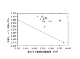
- the thrust that the nozzle vane tends to move toward the turbine housing / (the projected area on the pressure surface side of the nozzle vane) is 0.02 [N / mm 2 ] or more and 0 .05 [N / mm 2 ] or less is desirable.
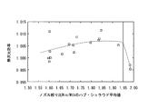
- the average value of the hub shroud of the nozzle channel length ratio L / Wth (L is the length of the nozzle channel, Wth is the outlet width of the nozzle channel) is greater than 1.5. Is desirable.
- the average value of the hub and shroud of the nozzle restriction ratio Win / Wth (Win is the inlet width of the nozzle flow path, Wth is the outlet width of the nozzle flow path) is less than 1.95.
- a trailing edge stacking line of the nozzle vane is parallel to an axis of the turbine impeller.
- the inclination angle of the downstream end portion of the exhaust gas of the nozzle vane with respect to the axis and the inclination angle of the leading edge of the blade of the turbine impeller with respect to the axis are different.
- the exhaust nozzle includes a support shaft that supports the nozzle vane, and a support hole that supports the support shaft is provided in at least one of the pair of exhaust introduction walls. It is desirable that the shaft is fixed to the nozzle vane via a flange portion protruding outward in the radial direction of the support shaft.
- the high-pressure side wall surface of the nozzle vane is preferably a curved surface.
- the nozzle vane is provided such that the bearing housing side is closer to the turbine impeller than the turbine housing side of the high-pressure side wall surface of the nozzle vane.
- exhaust gas is supplied to the scroll passage, and the exhaust gas passes between the pair of exhaust introduction walls of the exhaust nozzle by the rotation of the turbine impeller.
- the pressure of the exhaust gas acts on the high-pressure side wall surface of the nozzle vane perpendicularly to the high-pressure side wall surface.
- a component force in a direction of moving the nozzle vane toward the turbine housing or pressing the nozzle vane against the exhaust introduction wall on the turbine housing acts on the nozzle vane.
- the clearance gap between a nozzle vane and the exhaust introduction wall provided in the turbine housing side becomes small, and turbine efficiency improves. Therefore, according to the turbocharger of the present invention, the direction in which the nozzle vanes move can be controlled, and the turbine efficiency can be improved.
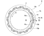
- FIG. 2 is a cross-sectional view of the exhaust nozzle taken along line AA in FIG.
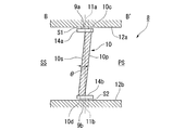
- FIG. 2B is a cross-sectional view taken along the line BB ′ in FIG. 2A.
- It is a perspective view of a turbine impeller. It is a perspective view of a turbine impeller and a nozzle vane.
- It is arrow sectional drawing equivalent to FIG. 2B of the modification in embodiment of this invention. It is arrow sectional drawing equivalent to FIG. 2B of the modification in embodiment of this invention. It is arrow sectional drawing equivalent to FIG. 2B of the modification in embodiment of this invention. It is arrow sectional drawing equivalent to FIG. 2B of the modification in embodiment of this invention. It is arrow sectional drawing equivalent to FIG.
- FIG. 2B of the modification in embodiment of this invention It is a perspective view of the turbine impeller and nozzle vane of the modification of this invention. It is a figure which shows the one part cross section which cut
- the turbocharger according to the present embodiment is a variable capacity turbocharger that can adjust the flow velocity and flow angle of exhaust gas supplied to a turbine impeller based on, for example, increase / decrease in gas flow accompanying increase / decrease in the number of rotations of an automobile engine. .
- the scale is appropriately changed for each member so that each member has a size that can be recognized on the drawing.
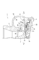
- FIG. 1 is a partially enlarged view of a cross-sectional view of the turbocharger of the present embodiment.
- the turbocharger 1 of the present embodiment includes a bearing housing (bearing housing) 3 that rotatably supports a turbine impeller 2.
- a turbine housing 5 is integrally attached to one side (the upper side in the drawing) of the bearing housing 3 by a plurality of bolts 4.
- a compressor housing (not shown) is integrally attached to the bearing housing 3 on the opposite side (lower side in the drawing) of the turbine housing 5 with a plurality of bolts.
- the turbine housing 5 includes a scroll flow path 5a that supplies exhaust gas to the turbine impeller 2, and an exhaust nozzle 8 that adjusts the flow velocity and flow angle of the exhaust gas supplied from the scroll flow path 5a to the turbine impeller 2 side. I have.
- the scroll flow path 5a is provided with an exhaust gas intake (not shown) connected to, for example, an engine cylinder.
- the exhaust nozzle 8 includes a first exhaust introduction wall 12a and a second exhaust introduction wall 12b that form an exhaust gas flow path.
- the first exhaust introduction wall 12 a is formed in a ring shape around the turbine impeller 2 and is disposed on the turbine housing 5 side.
- the second exhaust introduction wall 12b is formed in a ring shape around the turbine impeller 2, and is disposed on the bearing housing 3 side so as to face the first exhaust introduction wall 12a.
- the first exhaust introduction wall 12a and the second exhaust introduction wall 12b are integrally connected by a connection pin 8a.
- the exhaust nozzle 8 includes a plurality of nozzle vanes 10 arranged between the first exhaust introduction wall 12a and the second exhaust introduction wall 12b.
- the nozzle vanes 10 are evenly arranged around the turbine impeller 2 and are rotatably supported by support shafts 9a and 9b provided substantially parallel to the shaft 2a of the turbine impeller 2.
- the support shafts 9a and 9b are respectively fixed to an end portion of the nozzle vane 10 that faces the first exhaust introduction wall 12a and an end portion that faces the second exhaust introduction wall 12b, and are provided integrally with the nozzle vane 10. Yes.
- Support holes 11a and 11b for rotatably supporting the support shafts 9a and 9b are formed in the first exhaust introduction wall 12a and the second exhaust introduction wall 12b.
- the support shaft 9b is connected to a link mechanism 20 that transmits the power of an actuator (not shown) to the support shaft 9b and rotates the support shaft 9b.
- FIG. 2A is a cross-sectional view of the exhaust nozzle 8 taken along the line AA in FIG. 2B is a cross-sectional view of the vicinity of the nozzle vane 10 taken along the line BB ′ of FIG. 2A. 2A and 2B, the illustration of the connecting pin 8a is omitted.
- the nozzle vane 10 is formed in a streamlined wing-like shape in which the trailing edge 10a is thin and the leading edge 10b is thick in plan view.
- the rear edge 10a of the nozzle vane 10 is provided on the downstream side of the exhaust gas with respect to the support shafts 9a and 9b, and the front edge 10b is provided on the upstream side of the exhaust gas with respect to the support shafts 9a and 9b.
- the rear edge 10a is provided closer to the turbine impeller 2 than the front edge 10b. Further, the rear edge 10a is provided so as to be located on the front side in the rotational direction R of the turbine impeller 2 with respect to the front edge 10b.
- the side of the scroll flow path 5a outside the exhaust nozzle 8 is the high-pressure side PS of the exhaust gas
- the turbine impeller 2 side inside the exhaust nozzle 8 is the low-pressure side SS of the exhaust gas. Therefore, as shown in FIG. 2A, the side opposite to the turbine impeller 2 of the nozzle vane 10 is the high pressure side PS of the exhaust gas, and the turbine impeller 2 side of the nozzle vane 10 is the low pressure side SS of the exhaust gas.
- the nozzle vane 10 has a high-pressure side wall surface 10p on the high-pressure side PS facing the scroll flow path 5a, and a low-pressure side wall surface 10s on the low-pressure side SS facing the turbine impeller 2.
- the nozzle vane 10 is provided to be inclined at an inclination angle ⁇ with respect to the support shafts 9a and 9b and the shaft 2a of the turbine impeller 2.
- the high-pressure side wall surface 10p of the nozzle vane 10 is provided to be inclined with respect to the support shafts 9a and 9b and the shaft 2a of the turbine impeller 2.
- the first exhaust introduction wall 12a side of the high-pressure side wall surface 10p protrudes to the high-pressure side PS from the second exhaust introduction wall 12b side of the high-pressure side wall surface 10p.
- the high-pressure side wall surface 10p of the nozzle vane 10 is relative to the support shafts 9a and 9b and the shaft 2a of the turbine impeller 2 so that the bearing housing 3 side is closer to the turbine impeller 2 than the turbine housing 5 side, as shown in FIG. Are inclined.
- the support shafts 9a and 9b are provided with flange portions 14a and 14b projecting outward in the radial direction of the support shafts 9a and 9b at the end on the nozzle vane 10 side.
- the support shafts 9a and 9b are fixed to the respective end portions 10c and 10d of the nozzle vane 10 facing the first exhaust introduction wall 12a and the second exhaust introduction wall 12b via the flange portions 14a and 14b, respectively. .
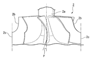
- FIG. 3A is a perspective view of the turbine impeller 2 of the turbocharger 1 of the present embodiment
- FIG. 3B is a perspective view showing the turbine impeller 2 and the nozzle vane 10.
- FIG. 3B other parts are omitted in order to show the relationship between the turbine impeller 2 and the nozzle vane 10.
- the turbine impeller 2 is provided with a plurality of blades 2 b that receive the pressure of the exhaust gas and rotate the turbine impeller 2.
- the front edge 2c of the blade 2b is provided to be inclined with an inclination angle ⁇ with respect to the shaft 2a of the turbine impeller 2.
- the rear edge 10a of the nozzle vane 10 is provided so as to be inclined with respect to the shaft 2a of the turbine impeller 2 at an inclination angle ⁇ .
- the inclination angle ⁇ with respect to the shaft 2a of the trailing edge 10a downstream of the exhaust gas of the nozzle vane 10 and the inclination angle ⁇ with respect to the shaft 2a of the front edge 2c of the blade 2b of the turbine impeller 2 are different.
- the turbocharger 1 of the present embodiment shown in FIG. 1 takes, for example, exhaust gas discharged from an engine cylinder into the scroll flow path 5a of the turbine housing 5, and the turbine impeller 2 through the exhaust nozzle 8. To supply. Thereby, the blades 2b of the turbine impeller 2 receive the exhaust gas, the turbine impeller 2 rotates, the shaft 2a rotates, and the compressor impeller rotates.
- the air taken in from the air intake and compressed by the rotation of the compressor impeller converts dynamic pressure energy into static pressure in the process of passing through the diffuser flow path, and is supplied to the compressor scroll flow path.
- the pressurized air in the compressor scroll passage is supplied from an air discharge port to, for example, an engine cylinder.
- the turbocharger 1 of the present embodiment includes an exhaust nozzle 8 that adjusts the flow velocity and flow angle of the exhaust gas supplied to the turbine impeller 2 based on, for example, increase or decrease of the gas flow rate accompanying the engine speed or the like. Yes.
- the link mechanism 20 is driven by a power source such as an actuator to rotate the support shaft 9b of the nozzle vane. Then, the plurality of nozzle vanes 10 rotate in synchronization with each support shaft 9b as a center.
- the angle at which the nozzle vane 10 is rotated can be adjusted, the opening degree of the exhaust nozzle 8 can be adjusted, and the flow velocity and flow angle of the exhaust gas supplied to the turbine impeller 2 can be adjusted.
- the exhaust gas that has passed between the first exhaust introduction wall 12a and the second exhaust introduction wall 12b of the exhaust nozzle 8 flows along the blades 2b of the turbine impeller 2 with the flow velocity and the flow angle adjusted,
- the turbine impeller 2 is rotated in the rotation direction R shown in FIG. 2A.
- the turbocharger 1 of the present embodiment is such that the high-pressure side wall surface 10p of the nozzle vane 10 provided on the high-pressure side PS of the exhaust gas is relative to the shaft 2a of the turbine impeller 2. Inclined at an inclination angle ⁇ .
- the high pressure side wall face 10p is inclined so that the second exhaust introduction wall 12b side (bearing housing 3 side) is closer to the turbine impeller 2 than the first exhaust introduction wall 12a side (turbine housing 5 side) of the high pressure side wall face 10p. is doing.
- the pressure P of the exhaust gas flowing from the scroll flow path 5a into the flow path between the first exhaust introduction wall 12a and the second exhaust introduction wall 12b of the exhaust nozzle 8 is applied to the inclined high pressure side wall face 10p. Acts vertically.
- the pressure P ′ of the exhaust gas also acts on the low pressure side wall surface 10s of the nozzle vane 10 perpendicularly.
- P> P ′ the first vane 10 is introduced into the nozzle vane 10 in parallel with the support shafts 9a and 9b and the component force (PP ′) cos ⁇ in the direction from the high-pressure side PS to the low-pressure side SS perpendicular to the support shafts 9a and 9b.
- a component force (PP ′) sin ⁇ in the direction toward the wall 12a acts.
- a gap S1 is provided between the nozzle vane 10 and the first exhaust introduction wall 12a, and a gap S2 is provided between the nozzle vane 10 and the second exhaust introduction wall 12b. ing. Therefore, the nozzle vane 10 is provided so as to be freely movable in the range of the gap S1 and the gap S2 in the direction parallel to the support shafts 9a and 9b.
- the nozzle vane 10 acts on the support shafts 9a, 9b. It hardly moves in the vertical direction.
- the pressure P of the exhaust gas acts perpendicularly to the high-pressure side wall surface 10p and the component force Psin ⁇ parallel to the support shafts 9a and 9b acts on the nozzle vane 10
- the nozzle vane 10 is parallel to the support shafts 9a and 9b. It moves to the first exhaust introduction wall 12a side.
- the above-described gap S1 may be zero and only the gap S2 may exist.
- the nozzle vane 10 presses the exhaust introduction wall 12a in the direction parallel to the support shafts 9a and 9b by the component force (PP ′) sin ⁇ parallel to the support shafts 9a and 9b acting on the nozzle vanes.
- the gap S1 between the end surface of the nozzle vane on the first exhaust introduction wall 12a side and the first exhaust introduction wall 12a becomes small.
- the resistance to the exhaust gas passing through the gap S1 increases.
- the flow rate of the exhaust gas passing through the gap S1 decreases.
- the flow rate of the exhaust gas that passes through the gap S1 decreases, the flow rate of the exhaust gas that passes between the high-pressure side wall surface 10p and the low-pressure side wall surface 10s of the adjacent nozzle vane 10 and the flow rate of the exhaust gas that passes through the gap S2 The sum is relatively increased.
- the exhaust gas supplied from the scroll flow path 5a which is the high pressure side PS of the exhaust gas to the turbine impeller 2 which is the low pressure side SS of the exhaust gas is
- the flow velocity and the flow angle according to the opening degree of the exhaust nozzle 8 are set.
- the turbine impeller 2 is adjusted to rotate in the rotation direction R.
- the exhaust gas passing through the gaps S1 and S2 between the nozzle vane 10 and the first exhaust introduction wall 12a and the second exhaust introduction wall 12b is between the high pressure side wall surface 10p and the low pressure side wall surface 10s of the nozzle vane 10 (described later).
- the contribution to the rotation of the turbine impeller 2 is small compared to the exhaust gas passing through the nozzle flow path 32).
- the gap S1 is reduced while the gap S2 is increased.
- the efficiency of rotating the turbine impeller 2 is significantly reduced.
- the nozzle vane 10 has more than the reduction in the efficiency of rotating the turbine impeller 2 due to the flow passing through the gap S2 increased by the movement of the nozzle vane 10 to the first exhaust introduction wall.
- the improvement in the efficiency of rotating the turbine impeller 2 due to the decrease in the flow passing through the gap S1 that has been reduced by moving to the greater is greater. Therefore, as a result, the nozzle vane 10 moves to the first exhaust introduction wall, whereby the turbine efficiency of the turbocharger 1 can be improved.
- the turbocharger 1 of the present embodiment has an inclination angle ⁇ of the trailing edge 10 a on the downstream side of the exhaust gas of the nozzle vane 10 and the front of the blade 2 b of the turbine impeller 2.
- the inclination angle ⁇ of the edge 2c with respect to the axis 2a is different.
- the inclination angle ⁇ of the trailing edge 10a of the nozzle vane 10 is equal to the inclination angle ⁇ of the front edge 2c of the blade 2b of the turbine impeller 2 with respect to the shaft 2a, the wake generated downstream of the nozzle vane 10 Simultaneously flow into the leading edge 2c of the blade 2b of the turbine impeller 2. Then, the excitation force to the turbine impeller 2 becomes large, and the turbine impeller 2, the turbine housing 5 and the like may be damaged by resonance. Therefore, conventionally, it has been necessary to incline the front edge 2c of the blade 2b of the turbine impeller 2 with respect to the shaft 2a of the turbine impeller 2.
- the nozzle vane 10 is inclined with respect to the axis of the turbine impeller 2. Therefore, even if the front edge 2c of the blade 2b of the turbine impeller 2 is not inclined, the inclination angle ⁇ of the front edge 2c and the inclination angle ⁇ of the end edge of the rear edge 10a of the nozzle vane 10 can be made different. As described above, when the inclination angle ⁇ and the inclination angle ⁇ are different, the inclination angle ⁇ and the inclination angle ⁇ can be set to arbitrary angles, respectively.
- the excitation angle to the turbine impeller 2 is reduced by making the inclination angle ⁇ with respect to the shaft 2a of the front edge 2c of the turbine impeller 2 different from the inclination angle ⁇ of the nozzle vane 10. Damage can be avoided by resonance. Further, since the inclination angle ⁇ of the nozzle vane 10 can be changed, the degree of freedom in designing the inclination angle ⁇ with respect to the shaft 2a of the front edge 2c of the turbine impeller 2 is increased.
- the turbocharger 1 of the present embodiment includes support shafts 9a and 9b on which the exhaust nozzle 8 supports the nozzle vanes 10.
- Support holes 11a and 11b for supporting the support shafts 9a and 9b are provided in the pair of first exhaust introduction walls 12a and the second exhaust introduction walls 12b, respectively.
- the support shafts 9b and 9b are fixed to the nozzle vane 10 via flanges 14a and 14b protruding outward in the radial direction of the support shafts 9a and 9b.
- the support shafts 9a and 9b can be fixed to the end portions 10c and 10d of the nozzle vane 10, respectively. Further, by supporting the support shafts 9a and 9b by the support holes 11a and 11b and supporting both ends 10c and 10d of the nozzle vane 10, it is possible to prevent the nozzle vane 10 from swinging. Thereby, it can prevent that the nozzle vane 10 bites into the 1st exhaust introduction wall 12a or the 2nd exhaust introduction wall 12b, or adheres.
- the direction in which the nozzle vane 10 moves can be controlled to the direction of the first exhaust introduction wall 12a, and the nozzle vane 10 and the first exhaust introduction wall 12a can be controlled.
- the gap S1 can be made relatively smaller than the gap S2 with the second exhaust introduction wall 12b, and the turbine efficiency can be improved.
- turbocharger 1 of the present embodiment differs from the shape of the nozzle vane 10 and the connection method between the support shafts 9a and 9b. Since the other points are the same as those of the above-described embodiment, the same parts are denoted by the same reference numerals and description thereof is omitted.
- FIG. 4A is a cross-sectional view corresponding to FIG. 2B showing a first modification of the turbocharger 1 described in the above embodiment.
- the high-pressure side wall surface 101p and the low-pressure side wall surface 101s of the nozzle vane 101 are curved surfaces.
- the support shaft 9a As the high-pressure side wall surface 101p approaches the first exhaust introduction wall 12a, the support shaft 9a.
- the inclination angle with respect to 9b becomes large, and the high-pressure side wall surface 101p is inclined so as to be away from the turbine impeller 2.
- FIG. 4B is a cross-sectional view corresponding to FIG. 2B showing a second modification of the turbocharger 1 described in the above embodiment.
- the high-pressure side wall surface 102p and the low-pressure side wall surface 102s of the nozzle vane 102 are curved surfaces.
- the support shaft 9a As the high-pressure side wall surface 102p approaches the second exhaust introduction wall 12b, the support shaft 9a. The inclination angle with respect to 9b is increased, and the high pressure side wall surface 102p is inclined so as to approach the turbine impeller 2.
- FIG. 4C is a cross-sectional view corresponding to FIG. 2B showing a third modification of the turbocharger 1 described in the above embodiment.
- the flanges 14a and 14b are not provided, and are directly fixed to the high-pressure side wall surface 103p and the low-pressure side wall surface 103s of the nozzle vane 103.
- the nozzle vane 103 can be moved to the first exhaust introduction wall 12a side as in the above-described embodiment even when the flange portions 14a and 14b are not provided. And the exhaust gas which passes the clearance gap S1 can be decreased and turbine efficiency can be improved.
- FIG. 4D is a cross-sectional view corresponding to FIG. 2B showing a fourth modification of the turbocharger 1 described in the above embodiment.
- the flange portions 14a and 14b are not provided, and only the high-pressure side wall surface 104p of the nozzle vane 104 is provided to be inclined.
- the low pressure side wall surface 104s of the nozzle vane 104 is provided substantially parallel to the support shafts 9a and 9b. According to such a configuration, the nozzle vane 104 can be moved to the first exhaust introduction wall 12a side as in the above-described embodiment. And the exhaust gas which passes the clearance gap S1 can be decreased and turbine efficiency can be improved.
- the support shaft may be provided only at the end facing the second exhaust introduction wall of the nozzle vane, and the nozzle vane may be supported in a cantilever manner.
- the link mechanism is provided on the turbine housing side of the exhaust nozzle, the support shaft may be provided only at the end portion of the nozzle vane facing the first exhaust introduction wall, and the nozzle vane may be supported in a cantilever manner.
- a line formed by the trailing edge 10a of the nozzle vane 10 shown in FIGS. 2A and 3B is referred to as a trailing edge stacking line S.
- the trailing edge stacking line S of the nozzle vane 105 may be parallel to the shaft 2a of the turbine impeller (the downstream side of the exhaust gas downstream of the nozzle vane in FIG. 3B).
- the inclination angle ⁇ of the edge with respect to the axis may be zero). This is defined as condition 1.
- FIG. 6 is a view showing a partial cross section of the nozzle vane shown in FIG. 2A cut along a plane perpendicular to the axis 2a of the turbine impeller.
- the nozzle channel length ratio L / Wth which is a dimensionless amount obtained by dividing L (the length of the nozzle channel 32) in FIG. 6 by Wth (the outlet width of the nozzle channel 32).
- L the length of the nozzle channel 32
- Wth the outlet width of the nozzle channel 32
- the average value of the shroud was taken on the horizontal axis.
- the dimensionless efficiency of the turbocharger including the nozzle vane according to the embodiment of the present invention is plotted on the vertical axis.
- the dimensionless efficiency with respect to the average value of the hub shroud of the nozzle flow path length ratio L / Wth was obtained, and a curve as shown in FIG. 7 was obtained. From this curve, it can be seen that when the average value of the hub shroud of the nozzle flow path length ratio L / Wth is larger than 1.5, the dimensionless efficiency exceeds 1, and thus a favorable result is obtained. From the above, the hub / shroud average value of the nozzle channel length ratio L / Wth may be larger than 1.5. This is Condition 2.
- FIG. 8 shows the nozzle aperture ratio Win / Wth obtained by dividing the nozzle channel inlet width Win in the nozzle channel 32 of FIG. 6 by the nozzle channel outlet width Wth on the nozzle vane hub side (the second exhaust introduction wall 12b). Side) and the shroud side (the first exhaust introduction wall 12a side) end face respectively, and the average value of the hub and shroud of the nozzle squeeze ratio Win / Wth obtained and averaged on the horizontal axis is the same as in FIG. It is the graph which took dimensional efficiency. Using the graph having the horizontal axis and the vertical axis, the dimensionless efficiency with respect to the hub / shroud average value of the nozzle aperture ratio Win / Wth was obtained, and a curve as shown in FIG.
- a total of four samples A, B, C, and D are created, consisting of three samples that do not satisfy any one of the above conditions 1 to 3 and one sample that satisfies all the conditions. did.
- the sample A is a sample that does not satisfy the condition 1 but satisfies the conditions 2 and 3.
- “ ⁇ ” indicates that the condition is met
- “x” indicates that the condition is not met.
- FIG. 9 is a graph in which the efficiency ratio ⁇ / ⁇ c obtained by dividing the turbine efficiency ( ⁇ c) of a turbocharger using a conventional nozzle by the turbine efficiency ( ⁇ ) of a turbocharger equipped with a nozzle vane according to the present invention is plotted on the vertical axis.
- the efficiency ratio with respect to the projected area on the thrust / pressure surface side was determined, and the results shown in FIG. 9 were obtained. From this, using the sample D that satisfies all the above conditions, when the projected area on the thrust / pressure surface side is 0.02 [N / mm 2 ] or more and 0.05 [N / mm 2 ] or less, It has been found that the most favorable results are obtained. Accordingly, the projected area on the thrust / pressure surface side may be 0.02 [N / mm 2 ] or more and 0.05 [N / mm 2 ] or less.
- the graph shows that the condition C is the second best, the condition B is the third best, and the condition A is the worst.
- the thrust for moving the nozzle vane toward the first exhaust introduction wall 12a is the nozzle vane.
- the nozzle vane cannot be moved against the frictional force acting on the lens, which is not desirable.
- the projected area on the thrust / pressure surface side is larger than 0.05 [N / mm 2 ], that is, when the inclination of the nozzle vane with respect to the turbine impeller shaft is too large, the inclination of the nozzle vane is too large.
- the energy loss of the working fluid (air) increases, and as a result, the turbine efficiency of the turbocharger decreases, which is undesirable.
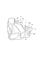
- the nozzle vane in the initial state, is arranged at the center of the flow path (the exhaust nozzle 8), the gap S1 between the nozzle vane and the first exhaust introduction wall 12a, the nozzle vane, and the second exhaust introduction. This was performed based on the conditions when the gap S2 with the wall 12b was equivalent. Furthermore, the present invention can be implemented in the following modifications. As shown in FIG. 10, the stacking line S at the front or rear edge of the nozzle vane 10 may not be perpendicular to the code direction of the nozzle vane. FIG.
- the trailing edge stacking line S of the nozzle vane 10 is not perpendicular to the nozzle vane cord direction (dashed line d in FIG. 10). That is, in the present modification, the stacking line S at the front edge or the rear edge of the nozzle vane 10 is not perpendicular to the cord direction of the nozzle vane, but the blade on the bearing housing side of the nozzle vane 10 is shifted upstream. Therefore, according to this modification, even when the bearing housing side of the nozzle vane 10 is provided so as to approach the turbine impeller side, like the nozzle vane 10 of the present invention shown in FIG. 2B, the nozzle vane 10 rotates and fully opens. The throat area for ensuring the capacity
- the direction in which the nozzle vanes move can be controlled, and the turbine efficiency can be improved.
Landscapes
- Engineering & Computer Science (AREA)
- Mechanical Engineering (AREA)
- General Engineering & Computer Science (AREA)
- Chemical & Material Sciences (AREA)
- Physics & Mathematics (AREA)
- Fluid Mechanics (AREA)
- Chemical Kinetics & Catalysis (AREA)
- General Chemical & Material Sciences (AREA)
- Combustion & Propulsion (AREA)
- Supercharger (AREA)
- Control Of Turbines (AREA)
Abstract
Description
本願は、2008年11月5日に日本国に出願された特願2008-284140号に基づき優先権を主張し、その内容をここに援用する。
これにより、排気導入壁に対面するノズルベーンの両端面の厚さ方向の寸法を大きくでき、十分なシール長が得られると共に、隙間流れも抑制できる。隙間流れを防止することで、タービン効率の低下を抑制することができる。
ターボチャージャの作動時には、スクロール流路に排気ガスが供給され、タービンインペラの回転によって排気ガスが排気ノズルの一対の排気導入壁の間を通過する。このとき、ノズルベーンの高圧側壁面には、排気ガスの圧力が高圧側壁面と垂直に作用する。
したがって、本発明のターボチャージャによれば、ノズルベーンが移動する方向を制御することができ、タービン効率を向上させることができる。
本実施形態のターボチャージャは、例えば自動車のエンジンの回転数の増減に伴うガス流量の増減に基づいてタービンインペラに供給する排気ガスの流速および流れ角度を調整可能な可変容量型のターボチャージャである。なお、以下の各図面では、各部材を図面上で認識可能な程度の大きさとするため、部材毎に縮尺を適宜変更している。
図1は、本実施形態のターボチャージャの断面図の部分拡大図である。
スクロール流路5aには、例えばエンジンのシリンダ等に接続された排気ガス取入口(図示略)が設けられている。
第1の排気導入壁12aは、タービンインペラ2の周囲にリング状に形成され、タービンハウジング5側に配置されている。
第2の排気導入壁12bは、同様にタービンインペラ2の周囲にリング状に形成され、第1の排気導入壁12aに対向してベアリングハウジング3側に配置されている。
第1の排気導入壁12aと第2の排気導入壁12bは、連結ピン8aにより一体的に連結されている。
ノズルベーン10は、タービンインペラ2の周囲に均等に配置され、タービンインペラ2の軸2aと略平行に設けられた支持軸9a,9bによって回動可能に支持されている。
第1の排気導入壁12a及び第2の排気導入壁12bには、支持軸9a,9bを回動可能に支持する支持穴11a,11bが形成されている。
支持軸9bは、アクチュエータ(不図示)の動力を支持軸9bに伝達して回動させるリンク機構20に連結されている。
そのため、図2Aに示すように、ノズルベーン10のタービンインペラ2と反対側が排気ガスの高圧側PSとなり、ノズルベーン10のタービンインペラ2側が排気ガスの低圧側SSとなっている。
ノズルベーン10は、スクロール流路5aに対向する高圧側PSに高圧側壁面10pを有し、タービンインペラ2に対向する低圧側SSに低圧側壁面10sを有している。
図3Bに示すように、ノズルベーン10の後縁10aは、タービンインペラ2の軸2aに対して傾斜角θの傾きで傾斜して設けられている。すなわち、ノズルベーン10の排気ガスの下流側の後縁10aの軸2aに対する傾斜角θとタービンインペラ2の羽根2bの前縁2cの軸2aに対する傾斜角γとが異なっている。
排気ノズル8の第1の排気導入壁12aと第2の排気導入壁12bとの間を通過した排気ガスは、流速および流れ角度が調整された状態でタービンインペラ2の羽根2bに沿って流れ、タービンインペラ2を図2Aに示す回転方向Rに回転させる。
本実施形態のターボチャージャ1は、図1、図2A及び図2Bに示すように、排気ガスの高圧側PSに設けられたノズルベーン10の高圧側壁面10pが、タービンインペラ2の軸2aに対して傾斜角θの傾きで傾斜して設けられている。高圧側壁面10pは、高圧側壁面10pの第1の排気導入壁12a側(タービンハウジング5側)よりも第2の排気導入壁12b側(ベアリングハウジング3側)がタービンインペラ2に近づくように傾斜している。
そのため、ノズルベーン10には、支持軸9a,9bと垂直に高圧側PSから低圧側SSへ向かう方向の分力(P-P’)cosθと、支持軸9a,9bと平行に第1の排気導入壁12aへ向かう方向の分力(P-P’)sinθが作用する。
しかし、排気ガスの圧力Pが高圧側壁面10pに垂直に作用して、ノズルベーン10に支持軸9a,9bと平行な分力Psinθが作用すると、ノズルベーン10は、支持軸9a,9bと平行に、第1の排気導入壁12a側に移動する。
なお、タービンインペラが回転する前のノズルベーンの位置によっては、上述の隙間S1がゼロで、隙間S2のみが存在する場合もある。この場合、上述のノズルベーンに作用する支持軸9a,9bと平行な分力(P-P’)sinθによって、ノズルベーン10は、排気導入壁12aを支持軸9a,9bと平行な方向に押し付けられる。
設計仕様によっては、ノズルベーン10の後縁10aの端縁の傾斜角θと、タービンインペラ2の羽根2bの前縁2cの軸2aに対する傾斜角γとが等しいと、ノズルベーン10の下流に生じる後流がタービンインペラ2の羽根2bの前縁2cに同時に流入する。すると、タービンインペラ2への励振力が大きくなり、共振によりタービンインペラ2やタービンハウジング5等が損傷する可能性がある場合がある。そのため、従来はタービンインペラ2の羽根2bの前縁2cをタービンインペラ2の軸2aに対して傾斜させる必要があった。
図4Aは、上述の実施の形態で説明したターボチャージャ1の第1の変形例を示す図2Bに対応する断面図である。
図4Aに示すように、本変形例では、ノズルベーン101の高圧側壁面101p及び低圧側壁面101sが曲面になっている。高圧側壁面101pは、第1の排気導入壁12aに近づくほど、支持軸9a.9bに対する傾斜角が大きくなり、かつ高圧側壁面101pがタービンインペラ2から遠ざかるように傾斜して設けられている。
このような構成によれば、上述の実施形態と同様の効果が得られるだけでなく、高圧側壁面101pの曲面の形状によってノズルベーン101に作用する圧力Pの支持軸9a,9bに平行な方向の分力の大きさを調整することができる。
図4Bは、上述の実施の形態で説明したターボチャージャ1の第2の変形例を示す図2Bに対応する断面図である。
図4Bに示すように、本変形例では、第1の変形例と同様に、ノズルベーン102の高圧側壁面102p及び低圧側壁面102sが曲面になっている。高圧側壁面102pは、第2の排気導入壁12bに近づくほど、支持軸9a.9bに対する傾斜角が大きくなり、かつ高圧側壁面102pがタービンインペラ2に近づくように傾斜して設けられている。
このような構成によれば、上述の実施形態と同様の効果が得られるだけでなく、高圧側壁面102pの曲面の形状によってノズルベーン102に作用する圧力Pの支持軸9a,9bに平行な方向の分力の大きさを調整することができる。
図4Cは、上述の実施の形態で説明したターボチャージャ1の第3の変形例を示す図2Bに対応する断面図である。
図4Cに示すように、本変形例では、鍔部14a,14bが設けられておらず、ノズルベーン103の高圧側壁面103p及び低圧側壁面103sに直接固定されている。
このような構成によれば、鍔部14a,14bが設けられていない場合であっても上述の実施形態と同様にノズルベーン103を第1の排気導入壁12a側に移動させることができる。そして、隙間S1を通過する排気ガスを減少させ、タービン効率を向上させることができる。
図4Dは、上述の実施の形態で説明したターボチャージャ1の第4の変形例を示す図2Bに対応する断面図である。
図4Dに示すように、本変形例では、鍔部14a,14bが設けられておらず、ノズルベーン104の高圧側壁面104pのみが傾斜して設けられている。ノズルベーン104の低圧側壁面104sは、支持軸9a,9bと略平行に設けられている。
このような構成によれば、上述の実施形態と同様にノズルベーン104を第1の排気導入壁12a側に移動させることができる。そして、隙間S1を通過する排気ガスを減少させ、タービン効率を向上させることができる。
図2Aや図3Bに示されているノズルベーン10の後縁10aにより形成されている線を後縁スタッキングラインSと呼ぶ。この時、図5に示すように、ノズルベーン105の前記後縁スタッキングラインSが、前記タービンインペラの前記軸2aと平行であっても良い(図3Bにおける前記ノズルベーンの前記排気ガスの下流側の後縁の前記軸に対する傾斜角θがゼロであっても良い)。これを条件1とする。
図6は、図2Aに示すノズルベーンをタービンインペラの軸2aに垂直な平面で切断した一部の断面を示す図である。図6のL(ノズル流路32の長さ)をWth(ノズル流路32の出口幅)で割った無次元量であるノズル流路長さ比L/Wth
をノズルベーンのハブ側(前記第2の排気導入壁12b側)端面とシュラウド側(前記第1の排気導入壁12a側)端面とでそれぞれ求め平均したノズル流路長さ比L/Wthのハブ・シュラウド平均値を横軸にとった。本発明による実施形態のノズルベーンを備えるターボチャージャの無次元効率を縦軸にとった。これら横軸と縦軸とを有するグラフを用いて、ノズル流路長さ比L/Wthのハブ・シュラウド平均値に対する無次元効率を求めたところ、図7に示すような曲線が得られた。この曲線より、ノズル流路長さ比L/Wthのハブ・シュラウド平均値が1.5より大きい場合、無次元効率が1を超えているため、好適な結果が得られたことが分かる。以上より、ノズル流路長さ比L/Wthのハブ・シュラウド平均値は1.5より大きくても良い。これを条件2とする。

さらに、本発明は以下のような変形例でも実施することができる。
図10に示されているように、ノズルベーン10の前縁もしくは後縁のスタッキングラインSが、ノズルベーンのコード方向に直角でなくてもよい。なお、図10は、ノズルベーン10の後縁スタッキングラインSがノズルベーンのコード方向(図10の一点鎖線c)に直角でない場合を示している。
つまり、本変形例では、ノズルベーン10の前縁もしくは後縁のスタッキングラインSが、ノズルベーンのコード方向に直角ではなく、ノズルベーン10のベアリングハウジング側の翼を上流側にずらしている。よって、本変形例によれば、図2Bに示す本発明のノズルベーン10のように、ノズルベーン10のベアリングハウジング側をタービンインペラ側に近づくように設けた場合であっても、ノズルベーン10が回転し全開の状態で得られるタービンインペラへ供給される排気ガスの容量(全開容量)を確保するためのスロート面積をより良好に確保することができる。従って、本発明のターボチャージャにおいて、好適に使用可能である。
2 タービンインペラ
2a 軸
2b 羽根
2c 前縁
3 ベアリングハウジング(軸受けハウジング)
5 タービンハウジング
5a スクロール流路
8 排気ノズル
9a,9b 支持軸
10 ノズルベーン
10a 後縁
10p 高圧側壁面
11a,11b 支持穴
12a,12b 排気導入壁
14a,14b 鍔部
32 ノズル流路
101 ノズルベーン
101p 高圧側壁面
102 ノズルベーン
102p 高圧側壁面
103 ノズルベーン
103p 高圧側壁面
104 ノズルベーン
104p 高圧側壁面
105 ノズルベーン
θ 傾斜角
γ 傾斜角
S 後縁スタッキングライン
Claims (13)
- タービンインペラを回転可能に支持する軸受けハウジングと、前記タービンインペラに排気ガスを供給するスクロール流路が形成されたタービンハウジングと、前記スクロール流路内から前記タービンインペラ側に供給される前記排気ガスの流速および流れ角度を可変とする排気ノズルと、を備えた可変容量型のターボチャージャにおいて、
前記排気ノズルは、前記排気ガスの流路を形成する一対の排気導入壁と、前記一対の排気導入壁の間に配置され前記タービンインペラの周囲に回動可能に支持された複数のノズルベーンと、を備え、
前記ノズルベーンは、前記スクロール流路に対向する高圧側壁面を有し、前記高圧側壁面の前記タービンハウジング側よりも前記軸受けハウジング側が前記タービンインペラに近づくように設けられており、前記タービンインペラの回転時に、前記一対の排気導入壁のうち、前記タービンハウジング側に設けられた排気導入壁と、前記ノズルベーンとの間の隙間を狭めるように、前記ノズルベーンが前記タービンハウジング側に移動する、または、前記ノズルベーンが前記タービンハウジング側の排気導入壁を押し付けるターボチャージャ。 - (前記ノズルベーンが前記タービンハウジング側に移動しようとする推力)/(前記ノズルベーンの圧力面側の投影面積)が、0.02[N/mm2]以上かつ0.05[N/mm2]以下である請求項1に記載のターボチャージャ。
- ノズル流路長さ比L/Wth(Lはノズル流路の長さ、Wthはノズル流路の出口幅)のハブ・シュラウド平均値が1.5より大きい請求項1または請求項2に記載のターボチャージャ。
- ノズル絞り比Win/Wth(Winはノズル流路の入口幅、Wthはノズル流路の出口幅)のハブ・シュラウド平均値が1.95より小さい請求項1または2に記載のターボチャージャ。
- ノズル絞り比Win/Wth(Winはノズル流路の入口幅、Wthはノズル流路の出口幅)のハブ・シュラウド平均値が1.95より小さい請求項3に記載のターボチャージャ。
- 前記ノズルベーンの後縁スタッキングラインが、前記タービンインペラの軸と平行である請求項1または請求項2に記載のターボチャージャ。
- 前記ノズルベーンの後縁スタッキングラインが、前記タービンインペラの軸と平行である請求項3に記載のターボチャージャ。
- 前記ノズルベーンの後縁スタッキングラインが、前記タービンインペラの軸と平行である請求項4に記載のターボチャージャ。
- 前記ノズルベーンの後縁スタッキングラインが、前記タービンインペラの軸と平行である請求項5に記載のターボチャージャ。
- 前記ノズルベーンの前記排気ガスの下流側の後縁の前記タービンインペラの軸に対する傾斜角と前記タービンインペラの羽根の前縁の前記タービンインペラの軸に対する傾斜角とが異なる請求項1記載のターボチャージャ。
- 前記排気ノズルは、前記ノズルベーンを支持する支持軸を備え、
前記一対の排気導入壁の少なくとも一方に、前記支持軸を軸支する支持穴が設けられ、
前記支持軸は、前記支持軸の径方向外側に張り出した鍔部を介して前記ノズルベーンに固定されている請求項1または請求項10に記載のターボチャージャ。 - 前記ノズルベーンの前記高圧側壁面は、曲面である請求項1または請求項10に記載のターボチャージャ。
- 前記ノズルベーンの前記高圧側壁面は、曲面である請求項11に記載のターボチャージャ。
Priority Applications (4)
| Application Number | Priority Date | Filing Date | Title |
|---|---|---|---|
| EP09824611.9A EP2351920B1 (en) | 2008-11-05 | 2009-11-05 | Turbocharger |
| CN200980143240.4A CN102203396B (zh) | 2008-11-05 | 2009-11-05 | 涡轮增压器 |
| JP2010536691A JP5035426B2 (ja) | 2008-11-05 | 2009-11-05 | ターボチャージャ |
| US13/127,514 US8807926B2 (en) | 2008-11-05 | 2009-11-05 | Turbocharger |
Applications Claiming Priority (2)
| Application Number | Priority Date | Filing Date | Title |
|---|---|---|---|
| JP2008284140 | 2008-11-05 | ||
| JP2008-284140 | 2008-11-05 |
Publications (1)
| Publication Number | Publication Date |
|---|---|
| WO2010052911A1 true WO2010052911A1 (ja) | 2010-05-14 |
Family
ID=42152724
Family Applications (1)
| Application Number | Title | Priority Date | Filing Date |
|---|---|---|---|
| PCT/JP2009/005888 Ceased WO2010052911A1 (ja) | 2008-11-05 | 2009-11-05 | ターボチャージャ |
Country Status (5)
| Country | Link |
|---|---|
| US (1) | US8807926B2 (ja) |
| EP (1) | EP2351920B1 (ja) |
| JP (1) | JP5035426B2 (ja) |
| CN (1) | CN102203396B (ja) |
| WO (1) | WO2010052911A1 (ja) |
Cited By (10)
| Publication number | Priority date | Publication date | Assignee | Title |
|---|---|---|---|---|
| EP2402558A1 (en) * | 2010-06-25 | 2012-01-04 | Honeywell International, Inc. | Vanes for directing exhaust to a turbine wheel |
| JP2013083252A (ja) * | 2011-10-12 | 2013-05-09 | General Electric Co <Ge> | 不均一可変ベーン |
| WO2014102962A1 (ja) * | 2012-12-27 | 2014-07-03 | 三菱重工業株式会社 | 可変容量型排気ターボ過給機 |
| WO2015002142A1 (ja) * | 2013-07-05 | 2015-01-08 | 株式会社Ihi | 可変ノズルユニット及び可変容量型過給機 |
| JPWO2014102981A1 (ja) * | 2012-12-27 | 2017-01-12 | 三菱重工業株式会社 | ラジアルタービン動翼 |
| WO2018088363A1 (ja) * | 2016-11-10 | 2018-05-17 | 株式会社Ihi | 可変ノズルユニットおよび過給機 |
| WO2018116395A1 (ja) * | 2016-12-21 | 2018-06-28 | 三菱重工エンジン&ターボチャージャ株式会社 | ターボチャージャ及びターボチャージャのノズルベーン並びにタービン |
| WO2019123565A1 (ja) * | 2017-12-20 | 2019-06-27 | 三菱重工エンジン&ターボチャージャ株式会社 | タービン及びターボチャージャ |
| US10844869B2 (en) | 2016-12-21 | 2020-11-24 | Mitsubishi Heavy Industries Engine & Turbocharger, Ltd. | Turbocharger, nozzle vane for turbocharger, and turbine |
| US10914190B2 (en) | 2016-11-01 | 2021-02-09 | Ihi Corporation | Variable nozzle unit and turbocharger |
Families Citing this family (23)
| Publication number | Priority date | Publication date | Assignee | Title |
|---|---|---|---|---|
| DE102011108195B4 (de) * | 2011-07-20 | 2022-10-27 | Ihi Charging Systems International Gmbh | Turbine für einen Abgasturbolader |
| US8967956B2 (en) * | 2011-09-26 | 2015-03-03 | Honeywell International Inc. | Turbocharger variable-nozzle assembly with vane sealing arrangement |
| US8967955B2 (en) * | 2011-09-26 | 2015-03-03 | Honeywell International Inc. | Turbocharger with variable nozzle having labyrinth seal for vanes |
| EP2787181B1 (en) * | 2011-11-30 | 2019-01-09 | Mitsubishi Heavy Industries, Ltd. | Radial turbine |
| EP2626515B1 (de) | 2012-02-10 | 2020-06-17 | MTU Aero Engines GmbH | Tandem-Schaufelgruppenanordnung |
| WO2013133312A1 (ja) * | 2012-03-09 | 2013-09-12 | 株式会社Ihi | タービンハウジング及び過給機 |
| JP5984446B2 (ja) * | 2012-03-23 | 2016-09-06 | 三菱重工業株式会社 | タービンハウジングアセンブリおよびタービンハウジングアセンブリの製造方法 |
| JP5986767B2 (ja) | 2012-03-23 | 2016-09-06 | 三菱重工業株式会社 | タービンハウジングアセンブリ |
| US9353637B2 (en) * | 2012-05-11 | 2016-05-31 | Honeywell International Inc. | Turbine exhaust housing |
| US9664060B2 (en) * | 2013-03-01 | 2017-05-30 | Ihi Corporation | Variable nozzle unit and variable geometry system turbocharger |
| DE102013225642B4 (de) * | 2013-12-11 | 2020-09-17 | Vitesco Technologies GmbH | Abgasturbolader mit einem verstellbaren Leitgitter |
| US9845684B2 (en) * | 2014-11-25 | 2017-12-19 | Pratt & Whitney Canada Corp. | Airfoil with stepped spanwise thickness distribution |
| US9810238B2 (en) * | 2015-03-09 | 2017-11-07 | Caterpillar Inc. | Turbocharger with turbine shroud |
| DE102015212808A1 (de) * | 2015-07-08 | 2017-01-12 | Continental Automotive Gmbh | Abgasturbolader mit verstellbarer Turbinengeometrie |
| WO2017168635A1 (ja) * | 2016-03-30 | 2017-10-05 | 三菱重工業株式会社 | ターボチャージャー |
| EP3954882B1 (en) * | 2016-03-30 | 2023-05-03 | Mitsubishi Heavy Industries Engine & Turbocharger, Ltd. | Variable geometry turbocharger |
| US11162375B2 (en) | 2017-02-22 | 2021-11-02 | Ihi Corporation | Turbocharger |
| US11421546B2 (en) * | 2019-02-25 | 2022-08-23 | Mitsubishi Heavy Industries Engine & Turbocharger, Ltd. | Nozzle vane |
| CN113557354B (zh) * | 2019-03-20 | 2023-07-14 | 株式会社Ihi | 可变容量型增压器 |
| CN113994072B (zh) * | 2019-06-14 | 2024-12-03 | 株式会社Ihi | 增压器 |
| US11156095B2 (en) * | 2019-07-29 | 2021-10-26 | Garrett Transportation I Inc. | Turbocharger turbine wheel |
| JP7444799B2 (ja) * | 2021-01-21 | 2024-03-06 | 三菱重工エンジン&ターボチャージャ株式会社 | 可変容量タービンおよび過給機 |
| CN114060094B (zh) * | 2021-11-16 | 2024-08-13 | 曾昭达 | 高压气体驱动涡轮机构 |
Citations (10)
| Publication number | Priority date | Publication date | Assignee | Title |
|---|---|---|---|---|
| JPS62138834U (ja) * | 1986-02-27 | 1987-09-01 | ||
| JPH11229815A (ja) | 1998-02-16 | 1999-08-24 | Ishikawajima Harima Heavy Ind Co Ltd | 可変容量型タービン |
| JPH11257011A (ja) | 1998-03-16 | 1999-09-21 | Ishikawajima Harima Heavy Ind Co Ltd | タービンのノズル構造 |
| JP2000018004A (ja) | 1998-07-01 | 2000-01-18 | Mitsubishi Heavy Ind Ltd | ノズル付きラジアルタービン |
| JP2000120442A (ja) * | 1998-10-12 | 2000-04-25 | Toyota Central Res & Dev Lab Inc | 可変容量形ターボチャージャ |
| JP2002147246A (ja) | 2000-11-15 | 2002-05-22 | Toyota Industries Corp | ターボチャージャ |
| JP2003301726A (ja) | 2002-04-08 | 2003-10-24 | Holset Eng Co Ltd | 可変形態タービン |
| US20050220616A1 (en) | 2003-12-12 | 2005-10-06 | Costas Vogiatzis | Vane and throat shaping |
| JP2007146695A (ja) * | 2005-11-24 | 2007-06-14 | Ishikawajima Harima Heavy Ind Co Ltd | 過給機 |
| JP2008184971A (ja) * | 2007-01-30 | 2008-08-14 | Ihi Corp | 可変容量型過給機 |
Family Cites Families (9)
| Publication number | Priority date | Publication date | Assignee | Title |
|---|---|---|---|---|
| CH638867A5 (de) * | 1979-03-16 | 1983-10-14 | Bbc Brown Boveri & Cie | Turbolader mit einer einrichtung zur regelung des schluckvermoegens der turbine. |
| JPS62138834A (ja) | 1985-12-12 | 1987-06-22 | Ricoh Co Ltd | アクテイブマトリクス型液晶表示装置 |
| US4741666A (en) * | 1985-12-23 | 1988-05-03 | Ishikawajima-Harima Jukogyo Kabushiki Kaisha | Variable displacement turbocharger |
| US6419464B1 (en) * | 2001-01-16 | 2002-07-16 | Honeywell International Inc. | Vane for variable nozzle turbocharger |
| GB0407978D0 (en) * | 2004-04-08 | 2004-05-12 | Holset Engineering Co | Variable geometry turbine |
| US7137778B2 (en) * | 2004-04-12 | 2006-11-21 | Borgwarner Inc. | Variable turbine geometry turbocharger |
| GB0426733D0 (en) * | 2004-12-06 | 2005-01-12 | Imp College Innovations Ltd | Flow control device for a turbocharger |
| GB0707501D0 (en) * | 2007-04-18 | 2007-05-30 | Imp Innovations Ltd | Passive control turbocharger |
| JP5201333B2 (ja) | 2008-03-11 | 2013-06-05 | 株式会社Ihi | 可変ノズルのベーン形状及び可変容量過給機 |
-
2009
- 2009-11-05 WO PCT/JP2009/005888 patent/WO2010052911A1/ja not_active Ceased
- 2009-11-05 EP EP09824611.9A patent/EP2351920B1/en active Active
- 2009-11-05 JP JP2010536691A patent/JP5035426B2/ja active Active
- 2009-11-05 US US13/127,514 patent/US8807926B2/en active Active
- 2009-11-05 CN CN200980143240.4A patent/CN102203396B/zh active Active
Patent Citations (10)
| Publication number | Priority date | Publication date | Assignee | Title |
|---|---|---|---|---|
| JPS62138834U (ja) * | 1986-02-27 | 1987-09-01 | ||
| JPH11229815A (ja) | 1998-02-16 | 1999-08-24 | Ishikawajima Harima Heavy Ind Co Ltd | 可変容量型タービン |
| JPH11257011A (ja) | 1998-03-16 | 1999-09-21 | Ishikawajima Harima Heavy Ind Co Ltd | タービンのノズル構造 |
| JP2000018004A (ja) | 1998-07-01 | 2000-01-18 | Mitsubishi Heavy Ind Ltd | ノズル付きラジアルタービン |
| JP2000120442A (ja) * | 1998-10-12 | 2000-04-25 | Toyota Central Res & Dev Lab Inc | 可変容量形ターボチャージャ |
| JP2002147246A (ja) | 2000-11-15 | 2002-05-22 | Toyota Industries Corp | ターボチャージャ |
| JP2003301726A (ja) | 2002-04-08 | 2003-10-24 | Holset Eng Co Ltd | 可変形態タービン |
| US20050220616A1 (en) | 2003-12-12 | 2005-10-06 | Costas Vogiatzis | Vane and throat shaping |
| JP2007146695A (ja) * | 2005-11-24 | 2007-06-14 | Ishikawajima Harima Heavy Ind Co Ltd | 過給機 |
| JP2008184971A (ja) * | 2007-01-30 | 2008-08-14 | Ihi Corp | 可変容量型過給機 |
Non-Patent Citations (2)
| Title |
|---|
| RAJOO, S., MARTINEZ-BOTAS, R. F.: "LEAN AND STRAIGHT NOZZLE VANES IN A VARIABLE GEOMETRY TURBINE : A STEADY AND PULSATING FLOW INVESTIGATION", PROC. OF ASME TURBO EXPO, 2008 |
| See also references of EP2351920A4 * |
Cited By (23)
| Publication number | Priority date | Publication date | Assignee | Title |
|---|---|---|---|---|
| US8834104B2 (en) | 2010-06-25 | 2014-09-16 | Honeywell International Inc. | Vanes for directing exhaust to a turbine wheel |
| EP2402558A1 (en) * | 2010-06-25 | 2012-01-04 | Honeywell International, Inc. | Vanes for directing exhaust to a turbine wheel |
| EP3048253A1 (en) * | 2010-06-25 | 2016-07-27 | Honeywell International Inc. | Vanes for directing exhaust to a turbine wheel |
| JP2013083252A (ja) * | 2011-10-12 | 2013-05-09 | General Electric Co <Ge> | 不均一可変ベーン |
| US9777578B2 (en) | 2012-12-27 | 2017-10-03 | Mitsubishi Heavy Industries, Ltd. | Radial turbine blade |
| WO2014102962A1 (ja) * | 2012-12-27 | 2014-07-03 | 三菱重工業株式会社 | 可変容量型排気ターボ過給機 |
| US10385765B2 (en) | 2012-12-27 | 2019-08-20 | Mitsubishi Heavy Industries Engine & Turbocharger, Ltd. | Variable geometry turbocharger |
| JP5936710B2 (ja) * | 2012-12-27 | 2016-06-22 | 三菱重工業株式会社 | 可変容量型排気ターボ過給機 |
| JPWO2014102981A1 (ja) * | 2012-12-27 | 2017-01-12 | 三菱重工業株式会社 | ラジアルタービン動翼 |
| JP2015014252A (ja) * | 2013-07-05 | 2015-01-22 | 株式会社Ihi | 可変ノズルユニット及び可変容量型過給機 |
| WO2015002142A1 (ja) * | 2013-07-05 | 2015-01-08 | 株式会社Ihi | 可変ノズルユニット及び可変容量型過給機 |
| DE112014003165B4 (de) | 2013-07-05 | 2023-08-03 | Ihi Corporation | Variable Düseneinheit und Turbolader mit variablem Geometriesystem |
| US10914190B2 (en) | 2016-11-01 | 2021-02-09 | Ihi Corporation | Variable nozzle unit and turbocharger |
| JPWO2018088363A1 (ja) * | 2016-11-10 | 2019-03-14 | 株式会社Ihi | 可変ノズルユニットおよび過給機 |
| WO2018088363A1 (ja) * | 2016-11-10 | 2018-05-17 | 株式会社Ihi | 可変ノズルユニットおよび過給機 |
| US11047256B2 (en) | 2016-11-10 | 2021-06-29 | Ihi Corporation | Variable nozzle unit and turbocharger |
| US10844869B2 (en) | 2016-12-21 | 2020-11-24 | Mitsubishi Heavy Industries Engine & Turbocharger, Ltd. | Turbocharger, nozzle vane for turbocharger, and turbine |
| US10851797B2 (en) | 2016-12-21 | 2020-12-01 | Mitsubishi Heavy Industries Engine & Turbocharger, Ltd. | Turbocharger, nozzle vane for turbocharger, and turbine |
| JPWO2018116395A1 (ja) * | 2016-12-21 | 2018-12-20 | 三菱重工エンジン&ターボチャージャ株式会社 | ターボチャージャ及びターボチャージャのノズルベーン並びにタービン |
| WO2018116395A1 (ja) * | 2016-12-21 | 2018-06-28 | 三菱重工エンジン&ターボチャージャ株式会社 | ターボチャージャ及びターボチャージャのノズルベーン並びにタービン |
| WO2019123565A1 (ja) * | 2017-12-20 | 2019-06-27 | 三菱重工エンジン&ターボチャージャ株式会社 | タービン及びターボチャージャ |
| JPWO2019123565A1 (ja) * | 2017-12-20 | 2020-12-17 | 三菱重工エンジン&ターボチャージャ株式会社 | タービン及びターボチャージャ |
| US11236669B2 (en) | 2017-12-20 | 2022-02-01 | Mitsubishi Heavy Industries Engine & Turbocharger, Ltd. | Turbine and turbocharger |
Also Published As
| Publication number | Publication date |
|---|---|
| US20110206500A1 (en) | 2011-08-25 |
| EP2351920B1 (en) | 2016-04-13 |
| JP5035426B2 (ja) | 2012-09-26 |
| EP2351920A1 (en) | 2011-08-03 |
| EP2351920A4 (en) | 2012-03-14 |
| US8807926B2 (en) | 2014-08-19 |
| CN102203396A (zh) | 2011-09-28 |
| JPWO2010052911A1 (ja) | 2012-04-05 |
| CN102203396B (zh) | 2014-01-29 |
Similar Documents
| Publication | Publication Date | Title |
|---|---|---|
| JP5035426B2 (ja) | ターボチャージャ | |
| JP5451247B2 (ja) | 受動的予旋回の逆方向回転のためのターボチャージャ連結 | |
| EP1741935A1 (en) | Centrifugal compressor and method of manufacturing impeller | |
| CN1576611A (zh) | 用于装配燃气涡轮发动机的方法和装置 | |
| WO2014102981A1 (ja) | ラジアルタービン動翼 | |
| JP2008128064A (ja) | 斜流タービンまたはラジアルタービン | |
| US10914190B2 (en) | Variable nozzle unit and turbocharger | |
| JP2010112223A (ja) | ターボチャージャ | |
| US10100841B2 (en) | Centrifugal compressor and system | |
| US11047256B2 (en) | Variable nozzle unit and turbocharger | |
| JP7123029B2 (ja) | 遠心圧縮機 | |
| CN111742125A (zh) | 涡轮机以及涡轮增压器 | |
| JP2012062767A (ja) | 2軸式ガスタービンの内周抽気構造及び2軸式ガスタービンにおける圧縮機最終段静翼の取付角設定方法 | |
| JP2012002140A (ja) | タービン及び過給機 | |
| RU2728549C1 (ru) | Аэродинамический профиль компрессора | |
| WO2021010338A1 (ja) | インペラ及びそれを用いた遠心圧縮機 | |
| JP2012241564A (ja) | ラジアルタービン及び過給機 | |
| JP2010127093A (ja) | ターボチャージャ | |
| CN110234888B (zh) | 压缩机的涡旋形状以及增压器 | |
| EP3456937B1 (en) | Turbocharger | |
| JP7643214B2 (ja) | 遠心式回転装置 | |
| JP7651986B2 (ja) | 遠心式回転装置 | |
| CN120882977A (zh) | 用于压缩机的叶轮、压缩机和涡轮增压器 | |
| WO2024070040A1 (ja) | 回転装置 |
Legal Events
| Date | Code | Title | Description |
|---|---|---|---|
| WWE | Wipo information: entry into national phase |
Ref document number: 200980143240.4 Country of ref document: CN |
|
| 121 | Ep: the epo has been informed by wipo that ep was designated in this application |
Ref document number: 09824611 Country of ref document: EP Kind code of ref document: A1 |
|
| WWE | Wipo information: entry into national phase |
Ref document number: 2010536691 Country of ref document: JP |
|
| WWE | Wipo information: entry into national phase |
Ref document number: 13127514 Country of ref document: US |
|
| NENP | Non-entry into the national phase |
Ref country code: DE |
|
| WWE | Wipo information: entry into national phase |
Ref document number: 2009824611 Country of ref document: EP |