WO2010053002A1 - リニアアクチュエータ - Google Patents
リニアアクチュエータ Download PDFInfo
- Publication number
- WO2010053002A1 WO2010053002A1 PCT/JP2009/067815 JP2009067815W WO2010053002A1 WO 2010053002 A1 WO2010053002 A1 WO 2010053002A1 JP 2009067815 W JP2009067815 W JP 2009067815W WO 2010053002 A1 WO2010053002 A1 WO 2010053002A1
- Authority
- WO
- WIPO (PCT)
- Prior art keywords
- rotation
- linear actuator
- way mechanism
- linear motion
- wedge
- Prior art date
- Legal status (The legal status is an assumption and is not a legal conclusion. Google has not performed a legal analysis and makes no representation as to the accuracy of the status listed.)
- Ceased
Links
Images


Classifications
-
- F—MECHANICAL ENGINEERING; LIGHTING; HEATING; WEAPONS; BLASTING
- F16—ENGINEERING ELEMENTS AND UNITS; GENERAL MEASURES FOR PRODUCING AND MAINTAINING EFFECTIVE FUNCTIONING OF MACHINES OR INSTALLATIONS; THERMAL INSULATION IN GENERAL
- F16D—COUPLINGS FOR TRANSMITTING ROTATION; CLUTCHES; BRAKES
- F16D41/00—Freewheels or freewheel clutches
- F16D41/06—Freewheels or freewheel clutches with intermediate wedging coupling members between an inner and an outer surface
- F16D41/08—Freewheels or freewheel clutches with intermediate wedging coupling members between an inner and an outer surface with provision for altering the freewheeling action
-
- B—PERFORMING OPERATIONS; TRANSPORTING
- B66—HOISTING; LIFTING; HAULING
- B66F—HOISTING, LIFTING, HAULING OR PUSHING, NOT OTHERWISE PROVIDED FOR, e.g. DEVICES WHICH APPLY A LIFTING OR PUSHING FORCE DIRECTLY TO THE SURFACE OF A LOAD
- B66F3/00—Devices, e.g. jacks, adapted for uninterrupted lifting of loads
- B66F3/08—Devices, e.g. jacks, adapted for uninterrupted lifting of loads screw operated
-
- B—PERFORMING OPERATIONS; TRANSPORTING
- B66—HOISTING; LIFTING; HAULING
- B66F—HOISTING, LIFTING, HAULING OR PUSHING, NOT OTHERWISE PROVIDED FOR, e.g. DEVICES WHICH APPLY A LIFTING OR PUSHING FORCE DIRECTLY TO THE SURFACE OF A LOAD
- B66F9/00—Devices for lifting or lowering bulky or heavy goods for loading or unloading purposes
- B66F9/06—Devices for lifting or lowering bulky or heavy goods for loading or unloading purposes movable, with their loads, on wheels or the like, e.g. fork-lift trucks
- B66F9/075—Constructional features or details
- B66F9/08—Masts; Guides; Chains
-
- F—MECHANICAL ENGINEERING; LIGHTING; HEATING; WEAPONS; BLASTING
- F16—ENGINEERING ELEMENTS AND UNITS; GENERAL MEASURES FOR PRODUCING AND MAINTAINING EFFECTIVE FUNCTIONING OF MACHINES OR INSTALLATIONS; THERMAL INSULATION IN GENERAL
- F16D—COUPLINGS FOR TRANSMITTING ROTATION; CLUTCHES; BRAKES
- F16D41/00—Freewheels or freewheel clutches
- F16D41/06—Freewheels or freewheel clutches with intermediate wedging coupling members between an inner and an outer surface
- F16D41/064—Freewheels or freewheel clutches with intermediate wedging coupling members between an inner and an outer surface the intermediate members wedging by rolling and having a circular cross-section, e.g. balls
- F16D41/066—Freewheels or freewheel clutches with intermediate wedging coupling members between an inner and an outer surface the intermediate members wedging by rolling and having a circular cross-section, e.g. balls all members having the same size and only one of the two surfaces being cylindrical
-
- F—MECHANICAL ENGINEERING; LIGHTING; HEATING; WEAPONS; BLASTING
- F16—ENGINEERING ELEMENTS AND UNITS; GENERAL MEASURES FOR PRODUCING AND MAINTAINING EFFECTIVE FUNCTIONING OF MACHINES OR INSTALLATIONS; THERMAL INSULATION IN GENERAL
- F16H—GEARING
- F16H25/00—Gearings comprising primarily only cams, cam-followers and screw-and-nut mechanisms
- F16H25/18—Gearings comprising primarily only cams, cam-followers and screw-and-nut mechanisms for conveying or interconverting oscillating or reciprocating motions
- F16H25/20—Screw mechanisms
- F16H25/24—Elements essential to such mechanisms, e.g. screws, nuts
- F16H25/2454—Brakes; Rotational locks
-
- Y—GENERAL TAGGING OF NEW TECHNOLOGICAL DEVELOPMENTS; GENERAL TAGGING OF CROSS-SECTIONAL TECHNOLOGIES SPANNING OVER SEVERAL SECTIONS OF THE IPC; TECHNICAL SUBJECTS COVERED BY FORMER USPC CROSS-REFERENCE ART COLLECTIONS [XRACs] AND DIGESTS
- Y10—TECHNICAL SUBJECTS COVERED BY FORMER USPC
- Y10T—TECHNICAL SUBJECTS COVERED BY FORMER US CLASSIFICATION
- Y10T74/00—Machine element or mechanism
- Y10T74/18—Mechanical movements
- Y10T74/18568—Reciprocating or oscillating to or from alternating rotary
- Y10T74/18576—Reciprocating or oscillating to or from alternating rotary including screw and nut
- Y10T74/18704—Means to selectively lock or retard screw or nut
Definitions
- the present invention relates to a linear actuator that linearly drives an object by converting the rotational motion of a rotational drive source such as a motor into a linear motion, particularly when the load direction is constant, such as the gravity of a load in a lift device.
- the present invention also relates to a linear actuator suitable for a case where a part of work performed when the actuator moves an object against the load is stored in the form of potential energy, spring elastic energy, or the like.
- a hydraulic linear actuator such as a hydraulic cylinder
- the hydraulic oil supply / exhaust path is blocked by a valve and the hydraulic oil is sealed.
- the electric actuator needs to be balanced with a load acting from the outside by generating a torque in the motor as a driving source, while it can be held without consuming any other power by confining it. That is, if it remains as it is, a part or all of the effect of reducing power consumption due to the conversion to the electric actuator will be lost.
- a rise in motor coil temperature during the holding period is a factor that impairs the durability of the device.
- the output shaft is linearly moved from the rotational drive source side such as a motor as disclosed in Japanese Patent Application Laid-Open No. 2007-32708 “Electric Linear Actuator”.
- a mechanism is disclosed that can only be driven and cannot move the output shaft linearly with a thrust load acting on the output shaft.
- the mechanism of the linear actuator described in Patent Document 1 certainly has the effect of eliminating the holding power and improving the durability of the motor, but conversely, the durability of the mechanism itself and the important purpose of electrification of the actuator It was the structure which left the problem that the applicability to the power regeneration which is one of them was not possible. In other words, it can be said that the configuration of an electric linear actuator that can fully bring out the merits of electrification and has excellent practicality has not yet been established.
- the linear actuator described in Patent Document 1 in order to hold the linear motion output shaft at the current position in a state where a load is applied from the driven object, the linear actuator is disposed between the output shaft and a member fixed in the axial direction. Thus, the wedge member is engaged with the wedge.
- a linear motion is generated from the rotation of a motor as a driving source by a rotation-linear motion conversion mechanism, and at the same time, the linear motion speed is reduced to generate a large thrust thrust.
- the reason why the thrust thrust must be increased is that a large load such as drive resistance acts from the driven object.
- the large load is directly supported by the wedge engaging portion, the large load is applied to each contact portion between the components of the wedge engaging mechanism, and the stress value of the contact portion is increased. It becomes a big factor to become high.
- a sphere is used as a rolling element that serves as a wedge member in the linear actuator described in Patent Document 1, and it can only contact a small area close to a point with other parts. It becomes a factor which raises a value further.
- One of the problems to be solved by the present invention is to reduce the stress value generated in the wedge engaging portion, and to realize an electric linear actuator having a small required holding power and excellent durability.
- the wedge engagement always causes the output shaft to linearly move even when the output shaft is linearly moved to rotate the motor as the rotational drive source. It stops at the stage by wedge engagement. That is, even if energy is stored in the driven object, it is not possible to perform power regeneration by reversing the motor as a generator.
- Another problem to be solved by the present invention is to realize an electric linear actuator capable of power regeneration.
- the present invention has the following configuration.
- the rotary member of the rotary drive path is rotationally driven by the rotary drive source, and the rotary motion is converted into the linear motion of the linear motion member by the rotation-linear motion conversion mechanism.
- the rotation member of the rotation drive path is allowed to rotate in the rotation drive direction with respect to the non-rotation member and is prevented from rotating in the opposite direction by wedge engagement.
- a one-way mechanism is configured, and the one-way mechanism is configured to have a switching function to a state in which the reverse rotation of the rotating member is allowed.
- the one-way mechanism in the linear actuator according to the first aspect of the present invention is the one in the circumferential direction between either the outer peripheral surface of the rotating member or the non-rotating member and the other inner peripheral surface.
- a one-way mechanism in which rolling elements are incorporated as wedge members in the gap and biased in the direction in which the gap is reduced by elastic means is arranged adjacent to the circumferential direction of the wedge member.
- the one-way mechanism is configured to allow the rotating member to rotate in the reverse direction.
- the rotating member in the rotational driving direction with respect to the non-rotating member.
- the one-way mechanism prevents rotation in the opposite direction and actively supplies power from the outside to allow reverse rotation.
- the invention according to claim 4 is the linear actuator according to claim 1, wherein at least a part of the external work due to the linear motion of the linear motion member is stored in the form of potential energy, elastic energy, or the like.
- the rotation-linear motion converting mechanism has a screw member formed with a spiral concave / convex groove and a nut member connected to the screw member by a screw pair, and a contact portion between the screw member and the nut member rolls.
- the rotating / linear motion converting mechanism is in contact, and the power regeneration is performed when the one-way mechanism is allowed to rotate in the reverse direction of the rotating member.
- a rotating member of the one-way mechanism that prevents rotation by wedge engagement is provided with a portion having a larger diameter than the other portions.
- a gap distribution that decreases toward one side in the circumferential direction is formed between the non-rotating member and the non-rotating member, and a rolling element is incorporated in the gap as a wedge member and is biased in a direction in which the gap is reduced by elastic means; did.
- the rotation member that prevents the one-way mechanism from rotating by the wedge engagement has a rotation speed (angular velocity) that is the highest in the rotation drive path.
- a rotating member was used.
- a plurality of wedge engaging mechanisms having a rolling element as a wedge member are arranged in a circumferential direction, and the non-rotating member of the one-way mechanism is arranged. Translational motion in a plane perpendicular to the axis was made possible, and it was constrained so that it could not rotate around the axis.
- the rotary drive device when the one-way mechanism allows the reverse rotation of the rotary member and starts power regeneration, the rotary drive device is temporarily driven to rotate. In this state, the one-way mechanism is switched to a state in which the rotating member is allowed to rotate in the reverse direction, and then the rotational driving torque of the rotational driving device is decreased to start power regeneration.
- the holding power can be reduced.
- the wedge engagement is performed not in the linear motion portion where a large thrust acts but in the rotational drive system path where the acting torque is relatively small, the contact force between the components of the wedge engagement is reduced to reduce the contact portion. Can be reduced.
- the rolling element as the wedge member in the one-way mechanism of the rotational drive path can use a cylindrical roller, the contact portion stress between the parts engaging with the wedge can be further reduced to reduce the contact portion stress. Therefore, durability is improved.
- the motor is rotated as a generator by the linear motion on the output shaft side, and power regeneration becomes possible.
- a specific configuration for realizing the wedge engagement of the one-way mechanism is presented, and the wedge engagement is prevented to allow the rotating member to rotate in the reverse direction.
- a specific configuration is also presented.
- the friction coefficient is greatly reduced compared to the case of sliding contact by making rolling contact between the relative motion parts in the rotation-linear motion conversion mechanism, so that rotation to linear motion can be achieved. Not only the conversion but also the mechanical efficiency in the conversion from the linear motion to the rotation can be improved. This makes it possible to secure a meaningful amount of recovery power for power regeneration.
- the torque is increased. What is necessary is just to generate
- the torque to be held by the one-way mechanism in the rotational drive path can be reduced even when the load acting on the linear motion output shaft does not change as follows. Even when the gears are shifted in the middle of the rotation drive path, if the friction loss at these gears is sufficiently small and ignored, the power transmitted at each rotational speed portion can be regarded as almost constant. Since the torque acting on each rotational speed portion is obtained by dividing the above-mentioned constant power by the angular velocity, the torque acting on the rotating member portion having the largest rotational speed is the smallest. Therefore, the stress generated in the wedge engaging portion is also minimized and the durability is improved.
- the non-rotating member automatically moves to a position where the wedge engaging forces in each of the plurality of wedge engaging mechanisms are balanced.
- the wedge engaging force in each wedge engaging mechanism can be equalized, and as a result, the wedge engaging force of some wedge engaging mechanisms can be prevented from increasing. Therefore, the stress generated in the wedge engaging portion is also minimized and the durability is improved.
- the eighth aspect of the present invention it is possible to greatly reduce the frictional resistance of a portion that must be driven when the one-way mechanism switches to a state in which the rotating member is allowed to rotate in the reverse direction for power regeneration.
- the above switching operation that is, power regeneration is substantially enabled.
- holding power which is power for holding an output shaft to which a load is applied from the outside in a fixed position. Further, it is possible to reduce the stress generated in the wedge engaging portion of the component and improve the durability. Moreover, it becomes possible to perform this power regeneration according to an instruction from the outside as necessary, and further power saving can be realized.
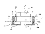
- FIG. 1 is a side sectional view of the entire configuration of the linear actuator in the present embodiment.
- 2 is a partially enlarged view of a portion A in FIG. 1
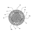
- FIG. 3 is a sectional view taken along line BB in FIG. 2
- FIG. 4 is a sectional view taken along line CC in FIG. .
- FIG. 6 is an explanatory view showing a state in which the one-way mechanism of the present embodiment functions and the rotational drive system cannot be reversed.
- FIGS. 6 (a) and 6 (b) are a DD sectional view and a CC line, respectively. Sectional drawing.
- FIG. 1 is a side sectional view of the entire configuration of the linear actuator in the present embodiment.
- 2 is a partially enlarged view of a portion A in FIG. 1
- FIG. 3 is a sectional view taken along line BB in FIG. 2
- FIG. 4 is a sectional view taken along line CC in FIG.
- FIG. 6 is an explanatory view showing a state
- FIG. 7 is an explanatory diagram showing a state in which the function of the one-way mechanism portion of this embodiment is blocked and the rotation drive system can be reversed.
- FIGS. 7A and 7B are DD views at that time, respectively. Sectional drawing and CC sectional drawing.
- a one-way mechanism portion A is configured on an output shaft 1a of a motor 1 which is a rotary drive device, and then a small gear 2 is fixed.
- a large gear 3 meshes with the small gear 2, and a screw shaft 4 is fixed to the large gear 3.
- the rotation of the small gear 2 is rotatably supported by the radial bearing 5 and the bearing of the motor 1, and the integrated large gear 3 and screw shaft 4 are supported by the radial bearing 6 and counteracted against the actuator thrust by the thrust bearing 7. Power is supported.
- the rotational drive path is configured as described above.
- Each of the above-described bearings and the like is incorporated between the lower housing 8 which is a fixed part and each rotating part of the rotation drive path.
- the nut member 9 is attached to the screw shaft 4 by a screw pair to constitute a screw mechanism, and both perform relative rotation and axial movement simultaneously.
- the screw shaft 4 and the nut member 9 are in contact with each other by rolling contact, and the frictional resistance between the screw shaft 4 and the nut member 9 is significantly smaller than that in the case of sliding contact.
- the screw mechanism that performs the rolling contact include a ball screw mechanism disclosed in Patent Document 1 and a revolving roller mechanism disclosed in Japanese Patent Application Laid-Open No. 2004-321043.
- a linear motion output member 10 is fixed to the nut member 9.
- the linear motion output member 10 is hollow in order to avoid interference with the screw shaft 4. Further, in this embodiment, the linear motion output member 10 is connected by a linear motion output member 11 and a coupling member 12 of another linear actuator represented by a one-dot chain line in FIG.
- the integrated nut member 9 is constrained so that it cannot rotate around the central axis.
- Other configurations that prevent the rotation of the linear output member 10 and the nut member 9 integrated therewith only around the central axis and permit the movement in the axial direction include one of them, and an upper housing described later.
- the structure etc. which connect 14 with a slide key etc. can also be considered.
- a central housing 13 is fixed on the lower housing 8, and a cylindrical upper housing 14 is fixed through the central housing 13.
- the upper housing 14 functions to support the nut member 9 and the screw shaft 4 so that the nut member 9 and the screw shaft 4 are not inclined by the inner peripheral surface 14a. Further, a seal is provided between the linear motion output member 10 and the outer peripheral surface of the linear motion output member 10 to prevent dust and the like from entering the screw pair of the screw shaft 4 and the nut member 9.
- the one-way mechanism part of the A part is incorporated between the central housing 13 and the output shaft 1 a of the motor 1.
- the slope forming member 15 in the one-way mechanism portion A shown in FIGS. 2 to 4 is a non-rotating member constrained so as not to rotate with respect to the central housing 13 via the Oldham ring 16.
- the pair of key portions 16 a formed on the lower surface of the Oldham ring 16 are respectively fitted into the pair of key groove portions 13 a formed in the central housing 13. You can move relative to the direction only.
- the pair of key portions 16b formed on the upper surface of the Oldham ring 16 are fitted into the pair of key groove portions 15a formed on the slope forming member 15, respectively.
- the relative movement is possible only in the groove direction.
- the inclined surface forming member 15 can translate (translate) in the plane perpendicular to the axis with respect to the central housing 13, but cannot rotate.
- the one-way mechanism portion is provided on the outer peripheral cylindrical surface 1 b of the large-diameter flange portion fixed to the output shaft 1 a of the motor 1 and on the inner periphery of the slope forming member 15.
- the component includes a biasing spring 18 that biases the spring.
- three inclined surfaces 15b, rollers 17 and biasing springs 18 are arranged in the circumferential direction at an angular pitch of 120 degrees. Further, a part of the roller holder 19 is arranged adjacent to each roller on the side opposite to the biasing spring 18, that is, the clockwise direction side of the biasing spring 18.
- the roller arm 19a that protrudes at one location on the outer periphery of the roller cage 19 is driven back and forth in the circumferential direction by moving the plunger 20a of the cage control solenoid 20 forward and backward.
- the cage 19 is rotationally driven with respect to the slope forming member 15 by a slight angle.
- the plunger 20a is moved rightward in FIG. 5 by the internal spring without energizing the exciting coil of the retainer control solenoid 20, and the roller retainer 19 is rotated in the clockwise direction.
- the plunger 20a moves to the left in FIG. 5 by the electromagnetic attractive force, and rotates the roller holder 19 in the counterclockwise direction.
- the screw shaft 4 rotates counterclockwise as viewed from above.
- the screw formed on the screw shaft 4 is a right-hand screw, so that the nut member 9 and the linear motion output member 10 that are constrained so as not to rotate when the screw shaft rotates counterclockwise are moved downward. Is linked to the linear motion. For this reason, the clockwise rotation of the output shaft 1a is prevented by the wedge engagement as described above, whereby the nut member 9 and the linear motion output member 10 are stopped from moving downward.
- the exciting coil of the cage control solenoid 20 is not energized, even if a downward external force acts on the linear motion output member 10, the linear motion output member 10 does not consume power using wedge engagement. Can hold the position.
- the output shaft 1a which is a member that stops movement by wedge engagement, is a rotating member.
- the linear motion output member 10 on which a large external force is acting can be held by stopping the output shaft 1a, which is a rotating member, with a small torque. Therefore, the stress generated in the wedge engaging portion can be made relatively small, and the fatigue life can be extended.
- the output shaft 1a that is a member that stops its movement by wedge engagement is compared with the screw shaft 4 that is a rotating member in the same rotational drive path.
- the torque acting at a large rotational speed is small.
- the selection of the output shaft 1a having a higher rotation speed among the rotating members and stopping the movement by the wedge engagement also contributes to reducing the stress generated in the wedge engaging portion and extending the fatigue life. .
- the actual wedge engagement is applied to the outer peripheral cylindrical surface 1b having a diameter larger than that of the shaft portion of the output shaft 1a.
- the slope forming member 15 is restrained in a non-rotating state with respect to the central housing 13, it can be translated in the plane perpendicular to the axis because of the Oldham ring 16. Therefore, if there is a difference in the tightening force of the three wedge engaging portions in FIG. 6B, the three contact forces acting on the slope forming member 15 as the reaction force are not balanced, and the slope forming member 15 As a result of translational movement in the plane perpendicular to the axis by the unbalanced force, the tightening force of the three wedge engaging portions is equalized, so that the maximum value of the stress generated in the wedge engaging portion can be suppressed from increasing. . This also contributes to extending the fatigue life.
- a screw mechanism in which the frictional resistance is reduced by rolling contact is adopted as the rotation-linear motion conversion mechanism. Even during the power regeneration described above, the reverse efficiency of the rotation-linear motion conversion mechanism is high, and the power regeneration efficiency is also high. A high value can be secured.
- the motor 1 is caused to function as an original rotational drive device, and a counterclockwise rotational drive torque is applied to the output shaft 1a of FIG. With this torque, the external force cancels out the torque that tries to rotate the output shaft 1a in the clockwise direction. As a result, the tension force and the frictional resistance acting on each roller 17 in FIG. 6B are reduced.
- the exciting coil of the cage control solenoid 20 is energized. If the frictional resistance is eliminated by the urging force acting on each roller 17, the force required to push them out is only the urging force by the urging spring 18, so that the magnetic attraction force of the cage control solenoid 20 is driven. As a force, the roller 17 is pushed out by the roller holder 19. Thereafter, the rotational driving torque of the motor 1 is reduced, and the power regeneration is started when the output shaft 1a starts to reversely rotate with the driving torque generated by the external force.
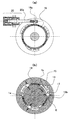
- FIG. 8 shows an example in which the present invention is applied to a forklift that is a working device for carrying a load as one of adaptation examples.
- a mast 101 is attached to the main body 100 of the forklift.
- the luggage lifting / lowering unit 102 attached to the mast 101 includes a holding frame 103 that is attached to the inner frame of the mast 5 via a lift bracket (not shown) so as to be raised and lowered, and a pair of forks 104 attached to the holding frame 103.
- the linear actuator 105 described in the above embodiment can be provided on the driver's seat side of the mast 101, for example.
- the linear actuator 105 does not require any power to hold the lift position when the load lifting section 102 is raised and stopped. Further, when machining, as described above, the internal output shaft is reversely rotated by the driving torque due to the external force, and power regeneration can be performed.
- the forklift provided with the linear actuator in the present embodiment does not require energy to raise and stop and hold the load at a specific position, and when processing the lifted and held load, It is possible to realize an electric forklift capable of effectively recovering.
Landscapes
- Engineering & Computer Science (AREA)
- General Engineering & Computer Science (AREA)
- Mechanical Engineering (AREA)
- Structural Engineering (AREA)
- Life Sciences & Earth Sciences (AREA)
- Geology (AREA)
- Transportation (AREA)
- Civil Engineering (AREA)
- Transmission Devices (AREA)
Abstract
Description
1a 出力軸
1b 外周円筒面
2 小歯車
3 大歯車
4 ネジ軸
5,6 ラジアル軸受
7 スラスト軸受
8 下部ハウジング
9 ナット部材
10,11 直動出力部材
12 連結部材
13 中央ハウジング
13a,15a キー溝部
14 上部ハウジング
14a 内周面
15 斜面形成部材
15b 傾斜面
16 オルダムリング
16a,16b キー部
17 ローラ
18 付勢バネ
19 ローラ保持器
19a 保持器アーム部
20 保持器制御ソレノイド
20a プランジャ
Claims (9)
- 回転駆動装置によって回転駆動経路の回転部材を回転駆動し、その回転運動を回転-直動変換機構によって直動部材の直動運動に変換し、その直動運動によって外部に対して仕事を行うリニアアクチュエータにおいて、上記回転駆動経路の回転部材が非回転部材に対して回転駆動方向に回転するのを許容しその逆方向に回転するのを楔係合によって阻止するワンウェイ機構を有し、そのワンウェイ機構は回転部材の上記逆方向回転も許容する状態に切り替える機能を有したことを特徴とするリニアアクチュエータ。
- 請求項1に記載のリニアアクチュエータにおいて、ワンウェイ機構は、回転部材と非回転部材のいずれか一方の外周面と他方の内周面との間に円周方向の一方に向かって減少する隙間分布を形成し、その隙間に転動体を楔部材として組み込んで弾性手段によって前記隙間の減少する方向に付勢したワンウェイ機構であり、楔部材の円周方向に隣接させて配置した保持部材とこれを外部からの指令によって円周方向に駆動する駆動手段を有し、前記楔部材を前記保持部材によって前記弾性手段による付勢方向と逆方向に押し出して楔係合を阻止しワンウェイ機構が回転部材の逆方向回転も許容する状態とすることを特徴とするリニアアクチュエータ。
- 請求項1または請求項2に記載のリニアアクチュエータにおいて、ワンウェイ機構は、外部から能動的に動力を供給しない状態では回転部材が非回転部材に対して回転駆動方向と逆方向に回転するのを阻止し、外部から能動的に動力を供給して逆方向回転も許容する状態とするワンウェイ機構であることを特徴とするリニアアクチュエータ。
- 請求項1に記載のリニアアクチュエータにおいて、直動部材の直動運動による外部仕事の少なくとも一部は、位置エネルギーや弾性エネルギーなどの形態で保存されるエネルギーであり、回転-直動変換機構は、螺旋状の凹凸溝を形成したネジ部材と、このネジ部材とネジ対偶によって連結されたナット部材とを構成要素に持ち、該ネジ部材とナット部材の接触部が転がり接触する回転-直動変換機構であり、ワンウェイ機構が回転部材の逆方向回転を許容して動力回生を行うことを特徴とするリニアアクチュエータ。
- 請求項2ないし請求項4のいずれかに記載のリニアアクチュエータにおいて、ワンウェイ機構が楔係合によって回転を阻止する回転部材は他の部分より径の大きな部分を有し、この部分と非回転部材との間に円周方向の一方に向かって減少する隙間分布を形成し、その隙間に転動体を楔部材として組み込んで弾性手段によって前記隙間の減少する方向に付勢したことを特徴とするリニアアクチュエータ。
- 請求項2ないし請求項4のいずれかに記載のリニアアクチュエータにおいて、ワンウェイ機構が楔係合によって回転を阻止する回転部材は、回転駆動経路において最も回転速度(角速度)の大きな回転部材であることを特徴とするリニアアクチュエータ。
- 請求項2に記載のリニアアクチュエータにおいて、転動体を楔部材とする楔係合機構を円周方向に複数配置し、ワンウェイ機構における非回転部材の軸直角面内での並進運動を可能とし、軸回りの回転はできないように拘束したことを特徴とするリニアアクチュエータ。
- 請求項4に記載のリニアアクチュエータにおいて、ワンウェイ機構が回転部材の逆方向回転を許容する状態にして動力回生を開始する際に、一旦、回転駆動装置が回転駆動トルクを発生している状態にし、その状態においてワンウェイ機構が回転部材の逆方向回転を許容する状態に切り替え、その後に回転駆動装置の回転駆動トルクを減少させて動力回生を開始することを特徴とするリニアアクチュエータ。
- 車両本体と、荷物昇降部が付設されるマストと、を備えた作業機械において、前記荷物昇降部を昇降させるリニアアクチュエータと、このリニアアクチュエータを駆動させる回転駆動装置とを有し、前記リニアアクチュエータは、前記回転駆動装置によって回転駆動する回転部材の回転運動を直動運動に変換する回転-直動変換機構と、前記回転部材が非回転部材に対して回転駆動方向に回転するのを許容しその逆方向に回転するのを楔係合によって阻止するワンウェイ機構とを有し、このワンウェイ機構は回転部材の上記逆方向回転も許容する状態に切り替える切り替え機能を有することを特徴とする作業機械。
Priority Applications (3)
| Application Number | Priority Date | Filing Date | Title |
|---|---|---|---|
| EP09824702A EP2354596A4 (en) | 2008-11-05 | 2009-10-14 | LINEAR ACTUATOR |
| US13/127,719 US20110259673A1 (en) | 2008-11-05 | 2009-10-14 | Linear actuator |
| CN200980143673XA CN102203462A (zh) | 2008-11-05 | 2009-10-14 | 线性驱动器 |
Applications Claiming Priority (2)
| Application Number | Priority Date | Filing Date | Title |
|---|---|---|---|
| JP2008283835A JP2010112409A (ja) | 2008-11-05 | 2008-11-05 | リニアアクチュエータ |
| JP2008-283835 | 2008-11-05 |
Publications (1)
| Publication Number | Publication Date |
|---|---|
| WO2010053002A1 true WO2010053002A1 (ja) | 2010-05-14 |
Family
ID=42152811
Family Applications (1)
| Application Number | Title | Priority Date | Filing Date |
|---|---|---|---|
| PCT/JP2009/067815 Ceased WO2010053002A1 (ja) | 2008-11-05 | 2009-10-14 | リニアアクチュエータ |
Country Status (6)
| Country | Link |
|---|---|
| US (1) | US20110259673A1 (ja) |
| EP (1) | EP2354596A4 (ja) |
| JP (1) | JP2010112409A (ja) |
| KR (1) | KR20110081266A (ja) |
| CN (1) | CN102203462A (ja) |
| WO (1) | WO2010053002A1 (ja) |
Families Citing this family (21)
| Publication number | Priority date | Publication date | Assignee | Title |
|---|---|---|---|---|
| JP5319320B2 (ja) * | 2009-02-17 | 2013-10-16 | 日立建機株式会社 | フォークリフト |
| JP2013057328A (ja) * | 2011-09-06 | 2013-03-28 | Hitachi Constr Mach Co Ltd | リフト機構の荷重保持機構 |
| CN102535906B (zh) * | 2012-02-24 | 2014-02-12 | 深圳市擎天达科技有限公司 | 多头螺杆幅升降机械式立体停车设备 |
| CN103057949A (zh) * | 2013-01-10 | 2013-04-24 | 浙江同济科技职业学院 | 一种机械搬运装置 |
| JP5737302B2 (ja) * | 2013-01-16 | 2015-06-17 | トヨタ自動車株式会社 | 内燃機関 |
| CN103527738B (zh) * | 2013-10-19 | 2015-12-23 | 段沧桑 | 一种实现升降旋转动作的机械机构 |
| US10183404B2 (en) | 2014-01-24 | 2019-01-22 | The Trustees Of The University Of Pennsylvania | Linear motion device with extending tube for positioning |
| FR3016860B1 (fr) * | 2014-01-27 | 2018-03-02 | Safran Electronics & Defense | Dispositif de blocage en rotation a structure simplifiee et actionneur comprenant un tel dispositif |
| FR3017600B1 (fr) * | 2014-02-20 | 2016-02-19 | Sagem Defense Securite | Actionneur a bloqueur et limiteur de couple associes |
| US20160181889A1 (en) * | 2014-12-22 | 2016-06-23 | Chin-Hsing Feng | Slide-type actuator |
| CN104528602B (zh) * | 2014-12-30 | 2017-06-20 | 江苏华澳橡胶机械有限公司 | 升降装置 |
| US20170335991A1 (en) * | 2016-05-20 | 2017-11-23 | Aktiebolaget Skf | Valve operator assembly with freewheel and friction means |
| US10501298B2 (en) * | 2017-04-04 | 2019-12-10 | Tyri International, Inc. | Linear actuator system for moving tines of a work vehicle |
| DE102017004664A1 (de) * | 2017-05-16 | 2018-11-22 | Horst Thiele Maschinenbau-Hydraulische Geräte GmbH | Linearblockiervorrichtung mit einer entlang einer Achse längsverschieblichen in einem Gehäuse geführten Lineareinrichtung und Baugruppensystem zur Sicherung und Freigabe von Personen, Gegenständen oder dergleichen mit einer derartigen Linearblockiervorrichtung |
| US11280388B1 (en) * | 2017-07-17 | 2022-03-22 | Empower Robotics Corporation | Multiple drive variable transmission ratio system with selective actuator engagement |
| CN108443472A (zh) * | 2018-05-11 | 2018-08-24 | 南京理工大学 | 一种三节式电动伸缩杆 |
| CN109534231B (zh) * | 2018-11-13 | 2020-06-12 | 林阿成 | 直升式堆叠装置 |
| CN109467024B (zh) * | 2018-11-15 | 2020-12-11 | 深圳若步智能科技有限公司 | 一种物流机器人 |
| CN110450177A (zh) * | 2019-08-23 | 2019-11-15 | 北京云迹科技有限公司 | 直线运动机构及具有其的机器人 |
| DE102020100439A1 (de) * | 2020-01-10 | 2021-07-15 | Logicdata Electronic & Software Entwicklungs Gmbh | Aktuatorsystem, Möbelstück und Verfahren zum Ansteuern eines Aktuatorsystems |
| CN111362150B (zh) * | 2020-04-13 | 2021-06-29 | 江西赣电电气有限公司 | 一种角度可调吊装设备 |
Citations (9)
| Publication number | Priority date | Publication date | Assignee | Title |
|---|---|---|---|---|
| JPH01154338U (ja) * | 1988-04-18 | 1989-10-24 | ||
| JPH0589973U (ja) * | 1992-03-24 | 1993-12-07 | エヌティエヌ株式会社 | ワンウェイクラッチユニット及びトルクリミッタユニット |
| JP2001106493A (ja) * | 1999-10-08 | 2001-04-17 | Murata Mach Ltd | 無人フォークリフト |
| JP2004011784A (ja) * | 2002-06-07 | 2004-01-15 | Ntn Corp | 一方向クラッチ |
| JP2005214088A (ja) * | 2004-01-30 | 2005-08-11 | Ntn Corp | 可変圧縮比エンジン用ボールねじアクチュエータ機構 |
| JP2005321043A (ja) | 2004-05-10 | 2005-11-17 | Hitachi Ltd | 回転直動変換機構 |
| JP2007032708A (ja) | 2005-07-27 | 2007-02-08 | Ntn Corp | 電動式直動アクチュエータおよび電動式ブレーキ装置 |
| JP2007162711A (ja) * | 2005-12-09 | 2007-06-28 | Kayaba Ind Co Ltd | 緩衝器 |
| WO2008001842A1 (fr) * | 2006-06-30 | 2008-01-03 | Ntn Corporation | Embrayage unidirectionnel |
Family Cites Families (3)
| Publication number | Priority date | Publication date | Assignee | Title |
|---|---|---|---|---|
| US2705939A (en) * | 1952-07-01 | 1955-04-12 | Gen Motors Corp | Fluid pressure actuator |
| FR2405405A1 (fr) * | 1977-10-07 | 1979-05-04 | Messier Hispano Sa | Verin mecanique a verrouillage |
| CN2545427Y (zh) * | 2002-05-17 | 2003-04-16 | 大银微系统股份有限公司 | 致动器自锁机构 |
-
2008
- 2008-11-05 JP JP2008283835A patent/JP2010112409A/ja active Pending
-
2009
- 2009-10-14 US US13/127,719 patent/US20110259673A1/en not_active Abandoned
- 2009-10-14 WO PCT/JP2009/067815 patent/WO2010053002A1/ja not_active Ceased
- 2009-10-14 KR KR1020117010126A patent/KR20110081266A/ko not_active Ceased
- 2009-10-14 CN CN200980143673XA patent/CN102203462A/zh active Pending
- 2009-10-14 EP EP09824702A patent/EP2354596A4/en not_active Withdrawn
Patent Citations (9)
| Publication number | Priority date | Publication date | Assignee | Title |
|---|---|---|---|---|
| JPH01154338U (ja) * | 1988-04-18 | 1989-10-24 | ||
| JPH0589973U (ja) * | 1992-03-24 | 1993-12-07 | エヌティエヌ株式会社 | ワンウェイクラッチユニット及びトルクリミッタユニット |
| JP2001106493A (ja) * | 1999-10-08 | 2001-04-17 | Murata Mach Ltd | 無人フォークリフト |
| JP2004011784A (ja) * | 2002-06-07 | 2004-01-15 | Ntn Corp | 一方向クラッチ |
| JP2005214088A (ja) * | 2004-01-30 | 2005-08-11 | Ntn Corp | 可変圧縮比エンジン用ボールねじアクチュエータ機構 |
| JP2005321043A (ja) | 2004-05-10 | 2005-11-17 | Hitachi Ltd | 回転直動変換機構 |
| JP2007032708A (ja) | 2005-07-27 | 2007-02-08 | Ntn Corp | 電動式直動アクチュエータおよび電動式ブレーキ装置 |
| JP2007162711A (ja) * | 2005-12-09 | 2007-06-28 | Kayaba Ind Co Ltd | 緩衝器 |
| WO2008001842A1 (fr) * | 2006-06-30 | 2008-01-03 | Ntn Corporation | Embrayage unidirectionnel |
Non-Patent Citations (1)
| Title |
|---|
| See also references of EP2354596A4 |
Also Published As
| Publication number | Publication date |
|---|---|
| KR20110081266A (ko) | 2011-07-13 |
| EP2354596A4 (en) | 2012-08-08 |
| JP2010112409A (ja) | 2010-05-20 |
| EP2354596A1 (en) | 2011-08-10 |
| US20110259673A1 (en) | 2011-10-27 |
| CN102203462A (zh) | 2011-09-28 |
Similar Documents
| Publication | Publication Date | Title |
|---|---|---|
| WO2010053002A1 (ja) | リニアアクチュエータ | |
| CN106321761B (zh) | 行星滚柱丝杠传动机构和具有其的执行器 | |
| JP4789000B2 (ja) | 減速比自動切換装置 | |
| KR101251215B1 (ko) | 와전류식 감속 장치 | |
| JP2019097363A (ja) | ギヤモータ及び協働ロボット | |
| CN1981142A (zh) | 致动机构及制动组件 | |
| EP2495852B1 (en) | Eddy-current brake | |
| JP2018061415A (ja) | アクチュエータ | |
| JP2009018412A (ja) | ロボットの関節駆動装置 | |
| WO2013035506A1 (ja) | リフト機構の荷重保持機構 | |
| JP4514021B2 (ja) | ボールねじアクチュエータ | |
| JP2019060477A (ja) | 減速機およびそれを用いたアクチュエータ | |
| JP2007504401A (ja) | 循環するラジアル荷重のための支承ユニット | |
| WO2012026020A1 (ja) | クラッチ装置 | |
| JP4283579B2 (ja) | 逆転防止機能を有する動力伝達装置 | |
| JP2010270886A (ja) | 電動アクチュエータ | |
| JP3941512B2 (ja) | クラッチ機構付リニアアクチュエータ | |
| JP2016017596A (ja) | 噛合式係合装置 | |
| JP2005291480A (ja) | 電動式リニアアクチュエータ | |
| JP2010121654A (ja) | 遊星差動式動力装置 | |
| JP2002233176A (ja) | 電動アクチュエータ | |
| WO2023276722A1 (ja) | ギヤードモータ、および、それを用いたクラッチアクチュエータ | |
| JP2018021587A (ja) | 車両用無段変速機 | |
| JP2021021417A (ja) | 回転伝達装置 | |
| JP2012215268A (ja) | 直線作動機 |
Legal Events
| Date | Code | Title | Description |
|---|---|---|---|
| WWE | Wipo information: entry into national phase |
Ref document number: 200980143673.X Country of ref document: CN |
|
| 121 | Ep: the epo has been informed by wipo that ep was designated in this application |
Ref document number: 09824702 Country of ref document: EP Kind code of ref document: A1 |
|
| ENP | Entry into the national phase |
Ref document number: 20117010126 Country of ref document: KR Kind code of ref document: A |
|
| WWE | Wipo information: entry into national phase |
Ref document number: 2009824702 Country of ref document: EP |
|
| NENP | Non-entry into the national phase |
Ref country code: DE |
|
| WWE | Wipo information: entry into national phase |
Ref document number: 13127719 Country of ref document: US |