WO2010055676A1 - 無線通信端末装置、無線通信基地局装置およびクラスタ配置設定方法 - Google Patents
無線通信端末装置、無線通信基地局装置およびクラスタ配置設定方法 Download PDFInfo
- Publication number
- WO2010055676A1 WO2010055676A1 PCT/JP2009/006086 JP2009006086W WO2010055676A1 WO 2010055676 A1 WO2010055676 A1 WO 2010055676A1 JP 2009006086 W JP2009006086 W JP 2009006086W WO 2010055676 A1 WO2010055676 A1 WO 2010055676A1
- Authority
- WO
- WIPO (PCT)
- Prior art keywords
- clusters
- cluster
- signal
- wireless communication
- base station
- Prior art date
- Legal status (The legal status is an assumption and is not a legal conclusion. Google has not performed a legal analysis and makes no representation as to the accuracy of the status listed.)
- Ceased
Links
Images




















Classifications
-
- H—ELECTRICITY
- H04—ELECTRIC COMMUNICATION TECHNIQUE
- H04W—WIRELESS COMMUNICATION NETWORKS
- H04W72/00—Local resource management
- H04W72/04—Wireless resource allocation
- H04W72/044—Wireless resource allocation based on the type of the allocated resource
- H04W72/0453—Resources in frequency domain, e.g. a carrier in FDMA
-
- H—ELECTRICITY
- H04—ELECTRIC COMMUNICATION TECHNIQUE
- H04B—TRANSMISSION
- H04B7/00—Radio transmission systems, i.e. using radiation field
- H04B7/02—Diversity systems; Multi-antenna system, i.e. transmission or reception using multiple antennas
- H04B7/04—Diversity systems; Multi-antenna system, i.e. transmission or reception using multiple antennas using two or more spaced independent antennas
- H04B7/0413—MIMO systems
- H04B7/0456—Selection of precoding matrices or codebooks, e.g. using matrices antenna weighting
-
- H—ELECTRICITY
- H04—ELECTRIC COMMUNICATION TECHNIQUE
- H04L—TRANSMISSION OF DIGITAL INFORMATION, e.g. TELEGRAPHIC COMMUNICATION
- H04L1/00—Arrangements for detecting or preventing errors in the information received
- H04L1/0001—Systems modifying transmission characteristics according to link quality, e.g. power backoff
- H04L1/0002—Systems modifying transmission characteristics according to link quality, e.g. power backoff by adapting the transmission rate
- H04L1/0003—Systems modifying transmission characteristics according to link quality, e.g. power backoff by adapting the transmission rate by switching between different modulation schemes
-
- H—ELECTRICITY
- H04—ELECTRIC COMMUNICATION TECHNIQUE
- H04L—TRANSMISSION OF DIGITAL INFORMATION, e.g. TELEGRAPHIC COMMUNICATION
- H04L1/00—Arrangements for detecting or preventing errors in the information received
- H04L1/0001—Systems modifying transmission characteristics according to link quality, e.g. power backoff
- H04L1/0009—Systems modifying transmission characteristics according to link quality, e.g. power backoff by adapting the channel coding
-
- H—ELECTRICITY
- H04—ELECTRIC COMMUNICATION TECHNIQUE
- H04L—TRANSMISSION OF DIGITAL INFORMATION, e.g. TELEGRAPHIC COMMUNICATION
- H04L27/00—Modulated-carrier systems
- H04L27/0008—Modulated-carrier systems arrangements for allowing a transmitter or receiver to use more than one type of modulation
-
- H—ELECTRICITY
- H04—ELECTRIC COMMUNICATION TECHNIQUE
- H04L—TRANSMISSION OF DIGITAL INFORMATION, e.g. TELEGRAPHIC COMMUNICATION
- H04L27/00—Modulated-carrier systems
- H04L27/26—Systems using multi-frequency codes
- H04L27/2601—Multicarrier modulation systems
- H04L27/2626—Arrangements specific to the transmitter only
- H04L27/2627—Modulators
- H04L27/2634—Inverse fast Fourier transform [IFFT] or inverse discrete Fourier transform [IDFT] modulators in combination with other circuits for modulation
- H04L27/2636—Inverse fast Fourier transform [IFFT] or inverse discrete Fourier transform [IDFT] modulators in combination with other circuits for modulation with FFT or DFT modulators, e.g. standard single-carrier frequency-division multiple access [SC-FDMA] transmitter or DFT spread orthogonal frequency division multiplexing [DFT-SOFDM]
-
- H—ELECTRICITY
- H04—ELECTRIC COMMUNICATION TECHNIQUE
- H04L—TRANSMISSION OF DIGITAL INFORMATION, e.g. TELEGRAPHIC COMMUNICATION
- H04L5/00—Arrangements affording multiple use of the transmission path
- H04L5/0001—Arrangements for dividing the transmission path
- H04L5/0003—Two-dimensional division
- H04L5/0005—Time-frequency
- H04L5/0007—Time-frequency the frequencies being orthogonal, e.g. OFDM(A) or DMT
-
- H—ELECTRICITY
- H04—ELECTRIC COMMUNICATION TECHNIQUE
- H04L—TRANSMISSION OF DIGITAL INFORMATION, e.g. TELEGRAPHIC COMMUNICATION
- H04L5/00—Arrangements affording multiple use of the transmission path
- H04L5/0001—Arrangements for dividing the transmission path
- H04L5/0014—Three-dimensional division
- H04L5/0016—Time-frequency-code
- H04L5/0021—Time-frequency-code in which codes are applied as a frequency-domain sequences, e.g. MC-CDMA
-
- H—ELECTRICITY
- H04—ELECTRIC COMMUNICATION TECHNIQUE
- H04L—TRANSMISSION OF DIGITAL INFORMATION, e.g. TELEGRAPHIC COMMUNICATION
- H04L5/00—Arrangements affording multiple use of the transmission path
- H04L5/0001—Arrangements for dividing the transmission path
- H04L5/0014—Three-dimensional division
- H04L5/0023—Time-frequency-space
-
- H—ELECTRICITY
- H04—ELECTRIC COMMUNICATION TECHNIQUE
- H04L—TRANSMISSION OF DIGITAL INFORMATION, e.g. TELEGRAPHIC COMMUNICATION
- H04L5/00—Arrangements affording multiple use of the transmission path
- H04L5/003—Arrangements for allocating sub-channels of the transmission path
- H04L5/0037—Inter-user or inter-terminal allocation
- H04L5/0041—Frequency-non-contiguous
-
- H—ELECTRICITY
- H04—ELECTRIC COMMUNICATION TECHNIQUE
- H04L—TRANSMISSION OF DIGITAL INFORMATION, e.g. TELEGRAPHIC COMMUNICATION
- H04L5/00—Arrangements affording multiple use of the transmission path
- H04L5/003—Arrangements for allocating sub-channels of the transmission path
- H04L5/0044—Allocation of payload; Allocation of data channels, e.g. PDSCH or PUSCH
- H04L5/0046—Determination of the number of bits transmitted on different sub-channels
-
- H—ELECTRICITY
- H04—ELECTRIC COMMUNICATION TECHNIQUE
- H04L—TRANSMISSION OF DIGITAL INFORMATION, e.g. TELEGRAPHIC COMMUNICATION
- H04L5/00—Arrangements affording multiple use of the transmission path
- H04L5/003—Arrangements for allocating sub-channels of the transmission path
- H04L5/0058—Allocation criteria
- H04L5/006—Quality of the received signal, e.g. BER, SNR, water filling
-
- H—ELECTRICITY
- H04—ELECTRIC COMMUNICATION TECHNIQUE
- H04L—TRANSMISSION OF DIGITAL INFORMATION, e.g. TELEGRAPHIC COMMUNICATION
- H04L5/00—Arrangements affording multiple use of the transmission path
- H04L5/0091—Signalling for the administration of the divided path, e.g. signalling of configuration information
- H04L5/0094—Indication of how sub-channels of the path are allocated
-
- H—ELECTRICITY
- H04—ELECTRIC COMMUNICATION TECHNIQUE
- H04J—MULTIPLEX COMMUNICATION
- H04J13/00—Code division multiplex systems
- H04J13/0007—Code type
- H04J13/0055—ZCZ [zero correlation zone]
- H04J13/0059—CAZAC [constant-amplitude and zero auto-correlation]
-
- Y—GENERAL TAGGING OF NEW TECHNOLOGICAL DEVELOPMENTS; GENERAL TAGGING OF CROSS-SECTIONAL TECHNOLOGIES SPANNING OVER SEVERAL SECTIONS OF THE IPC; TECHNICAL SUBJECTS COVERED BY FORMER USPC CROSS-REFERENCE ART COLLECTIONS [XRACs] AND DIGESTS
- Y02—TECHNOLOGIES OR APPLICATIONS FOR MITIGATION OR ADAPTATION AGAINST CLIMATE CHANGE
- Y02D—CLIMATE CHANGE MITIGATION TECHNOLOGIES IN INFORMATION AND COMMUNICATION TECHNOLOGIES [ICT], I.E. INFORMATION AND COMMUNICATION TECHNOLOGIES AIMING AT THE REDUCTION OF THEIR OWN ENERGY USE
- Y02D30/00—Reducing energy consumption in communication networks
- Y02D30/50—Reducing energy consumption in communication networks in wire-line communication networks, e.g. low power modes or reduced link rate
Definitions
- the present invention relates to a wireless communication terminal device, a wireless communication base station device, and a cluster arrangement setting method.
- Orthogonal Frequency Division Multiplexing is adopted as a downlink (DL) multiple access scheme to realize low delay and high speed transmission, and DFT (Discrete) as an uplink (UL) multiple access scheme.
- SC-FDMA Single-Carrier Frequency Division Multiple Access
- SC-FDMA Single-Carrier Frequency Division Multiple Access
- an SC-FDMA signal is formed by spreading and code multiplexing symbol sequences using a DFT matrix (precoding matrix or DFT sequence).
- LTE-Advanced or IMT (International Mobile Telecommunication) -Advanced
- a wireless communication base station hereinafter referred to as a base station
- a wireless communication terminal hereinafter referred to as a terminal
- uplink frequency resource allocation is SC-FDMA in order to maintain single carrier characteristics (for example, low PAPR (Peak-to-Average Power Ratio) characteristics) of a transmission signal that achieves high coverage.
- the assignment is limited to mapping the signal locally to a continuous frequency band.
- C-SC-FDMA clustered SC-FDMA
- a base station In C-SC-FDMA, a base station is in idle state of a plurality of uplink frequency resources (subcarriers or resource blocks (RBs)) or channel quality information between a plurality of terminals and the base station (For example, CQI: Channel Quality Indicator) is compared. Then, the base station generates a plurality of clusters by dividing the SC-FDMA signal (spectrum) of each terminal by an arbitrary bandwidth according to the quality of CQI between each terminal and the own station. . Then, the base station assigns each of the plurality of generated clusters to a plurality of uplink frequency resources, and notifies the terminal of information indicating the assignment result.
- SC-FDMA SC-FDMA signal
- the terminal divides the SC-FDMA signal (spectrum) with an arbitrary bandwidth and maps the C-SC-FDMA signal by mapping a plurality of clusters on a plurality of uplink frequency resources allocated by the base station. Generate Then, the base station performs frequency domain equalization (FDE) processing on the received C-SC-FDMA signal (a plurality of clusters), and combines the plurality of clusters after the equalization processing. The base station then performs IDFT (Inverse Discrete Fourier Transform) processing on the combined signal to obtain a signal in the time domain.
- FDE frequency domain equalization
- IDFT Inverse Discrete Fourier Transform
- C-SC-FDMA frequency resource allocation between a plurality of terminals can be performed more flexibly than SC-FDMA by mapping a plurality of clusters to a plurality of discontinuous frequency resources. For this reason, C-SC-FDMA can improve the multi-user diversity effect, and as a result, it is possible to improve system throughput (see, for example, Non-Patent Document 2).
- LTE-Advanced uplink in order to realize faster communication than LTE, not only system throughput is improved, but also user throughput for each terminal is improved compared to user throughput for each terminal in LTE uplink You need to
- the uplink wide band radio frequency band (wide band radio channel) has frequency selectivity, the frequency correlation between channels in which a plurality of clusters mapped to different discontinuous frequency bands are respectively propagated is low. Therefore, even when the base station equalizes the C-SC-FDMA signal (a plurality of clusters) by the equalization process, the equivalent channel gains per plurality of clusters (that is, the frequency channel gains after FDE weight multiplication) differ greatly It is possible. Therefore, the equivalent channel gain may change rapidly at the connection point of a plurality of clusters (that is, the dividing point at which the terminal divides the SC-FDMA signal). That is, discontinuities may occur in the variation of the equivalent channel gain (i.e., the envelope of the reception spectrum) at the connection point of a plurality of clusters.
- the equivalent channel gain i.e., the envelope of the reception spectrum
- the equivalent channel gain needs to be a slow variation in all frequency bands to which a plurality of clusters are mapped. Therefore, as described above, when a discontinuity occurs in the variation of equivalent channel gain at the junction of a plurality of clusters, the orthogonality of the DFT matrix is large in the frequency band to which the C-SC-FDMA signal is mapped. It collapses. Therefore, the C-SC-FDMA signal is susceptible to inter-symbol interference (ISI) caused by the collapse of the orthogonality of the DFT matrix.
- ISI inter-symbol interference
- MCS Modulation and channel Coding Scheme
- coding rate and modulation level coding rate and modulation level
- transmission parameters are set.
- the tolerance to ISI (reception sensitivity) due to the collapse of orthogonality of the DFT matrix, that is, the magnitude of allowable ISI (hereinafter referred to as allowable ISI) is different for each transmission parameter set in the SC-FDMA signal.
- modulation schemes with higher modulation levels such as modulation schemes such as 64 QAM with a very short Euclidean distance between signal points, are more affected by ISI. It is easy to receive.
- the SC-FDMA signal is divided by an arbitrary bandwidth according to only the CQI between the base station and each terminal as in the above-mentioned prior art, and multiple clusters are mapped to discontinuous frequency bands, respectively.
- system throughput is improved, differences in transmission parameters (MCS set or coding size) set for SC-FDMA signals cause variations in the influence of ISI on transmission characteristics and user throughput is not improved. .
- An object of the present invention is to improve system throughput even when SC-FDMA signal is divided into a plurality of clusters and a plurality of clusters are mapped to discontinuous frequency bands respectively, that is, even when C-SC-FDMA is used.
- the wireless communication terminal device of the present invention performs DFT processing on a symbol sequence in the time domain to generate a signal in the frequency domain, an MCS set set for the signal, and an encoding size set for the signal.
- the plurality of clusters are divided by dividing the signal into a plurality of clusters and mapping the plurality of clusters to a plurality of discontinuous frequency resources according to a cluster pattern according to the number of ranks in MIMO transmission.
- setting means for setting the arrangement in the frequency domain are provided to generate a signal in the frequency domain, an MCS set set for the signal, and an encoding size set for the signal.
- the plurality of clusters are divided by dividing the signal into a plurality of clusters and mapping the plurality of clusters to a plurality of discontinuous frequency resources according to a cluster pattern according to the number of ranks in MIMO transmission.
- setting means for setting the arrangement in the frequency domain.
- the wireless communication base station apparatus is a cluster of the signal according to an MCS set set to a signal from a wireless communication terminal apparatus, a coding size set to the signal, or a Rank number at the time of MIMO transmission.
- a control unit configured to determine a pattern, and a notification unit configured to notify the wireless communication terminal apparatus of the cluster pattern are employed.
- an MCS set set to a signal in the frequency domain generated by performing DFT processing on a symbol sequence in the time domain, a coding size set to the signal, or MIMO transmission According to a cluster pattern according to the number of ranks, the signal is divided into a plurality of clusters, and the plurality of clusters are mapped to a plurality of discontinuous frequency resources to set the arrangement of the plurality of clusters.
- the improvement effect of the system throughput is obtained.
- User throughput can be improved while maintaining
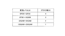
- FIG. 6 is a diagram showing the correspondence between the modulation level and the number of clusters or the cluster size according to Embodiment 1 of the present invention.
- FIG. 7 is a diagram showing a setting method of cluster arrangement according to the first embodiment of the present invention (when the modulation level is low)
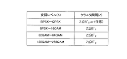
- FIG. 6 is a diagram showing the correspondence between modulation levels and cluster intervals according to Embodiment 1 of the present invention.
- FIG. 7 is a diagram showing a setting method of cluster arrangement according to the first embodiment of the present invention (when the modulation level is low)
- a diagram showing a setting method of cluster arrangement according to the first embodiment of the present invention (when the modulation level is high) The figure which shows the signal after the combination which concerns on Embodiment 1 of this invention (when a modulation level is low)
- FIG. 6 is a diagram showing correspondence between coding size and cluster interval according to Embodiment 1 of the present invention.
- FIG. 6 is a diagram showing correspondence between coding size and cluster interval according to Embodiment 1 of the present invention.
- FIG. 6 shows a method of setting a cluster arrangement according to Embodiment 1 of the present invention (when the coding size is large)
- FIG. 6 shows a method of setting a cluster arrangement according to Embodiment 1 of the present invention (when the coding size is small)
- FIG. 6 is a diagram showing the correspondence between the coding rate and the number of clusters or the cluster size according to Embodiment 1 of the present invention.
- FIG. 6 is a diagram showing correspondence between coding size and cluster interval according to Embodiment 1 of the present invention.
- a diagram showing correspondence between encoding size and number of clusters according to a variation of the first embodiment of the present invention A diagram showing correspondence between encoding size and cluster size according to a variation of the first embodiment of the present invention
- a diagram showing correspondence between encoding size and cluster size according to a variation of the first embodiment of the present invention A diagram showing correspondence between encoding size and cluster interval according to a variation of the first embodiment of the present invention
- a diagram showing correspondence between encoding size and cluster size according to a variation of the first embodiment of the present invention A diagram showing correspondence between encoding size and cluster size according to a variation of the first embodiment of the present invention
- a diagram showing correspondence between encoding size and cluster size according to a variation of the first embodiment of the present invention A diagram showing correspondence between encoding size and cluster interval according to a variation of the first embodiment of the present invention
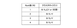
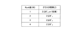
- Diagram showing a setting method of cluster arrangement according to Embodiment 2 of the present invention (when the number of Ranks is small) Diagram showing a setting method of cluster arrangement according to Embodiment 2 of the present invention (when the number of Ranks is large) The figure which shows matching with the number of Ranks, and a cluster space
- FIG. 12 is a diagram showing a method of setting a cluster arrangement according to Embodiment 2 of the present invention (case of Rank number 2) Terminal block diagram according to Embodiment 2 of the present invention (case of 4 ranks)
- FIG. 12 is a diagram showing a method of setting a cluster arrangement according to Embodiment 2 of the present invention (case of Rank number 2)
- FIG. 16 is a diagram showing the correspondence between the transmission rate (MCS set) and the number of clusters or the cluster size according to Embodiment 2 of the present invention.
- FIG. 10 is a diagram showing a method of setting a cluster arrangement according to Embodiment 2 of the present invention.
- FIG. 6 is a diagram showing the correspondence between a transmission rate (MCS set) and cluster intervals according to Embodiment 2 of the present invention.
- FIG. 10 is a diagram showing a method of setting a cluster arrangement according to Embodiment 2 of the present invention.
- Embodiment 1 The configuration of base station 100 according to the present embodiment is shown in FIG.
- radio reception section 102 receives the C-SC-FDMA signal transmitted from each terminal via antenna 101, and performs down conversion, A / D conversion, etc. on the C-SC-FDMA signal. Perform reception processing. Then, the wireless reception unit 102 outputs the C-SC-FDMA signal subjected to the reception process to a CP (Cyclic Prefix) removal unit 103.
- CP Cyclic Prefix
- CP removing section 103 removes the CP attached to the head of the C-SC-FDMA signal input from radio receiving section 102.
- the FFT (Fast Fourier Transform) unit 104 performs FFT on the C-SC-FDMA signal input from the CP removal unit 103 to convert it into a C-SC-FDMA signal (subcarrier component) in the frequency domain. Then, FFT section 104 outputs the C-SC-FDMA signal (subcarrier component) in the frequency domain to demapping section 105. Further, FFT section 104 outputs the subcarrier component including the pilot signal to measurement section 111.
- Demapping section 105 uses the C-SC-FDMA signal input from FFT section 104 to the frequency resource (subcarrier or RB) used by each terminal based on the mapping information input from control section 113. Extract the C-SC-FDMA signal of the corresponding part. Then, the demapping unit 105 outputs the extracted C-SC-FDMA signal to the FDE unit 106.
- the FDE unit 106 receives the C signal input from the demapping unit 105 using the FDE weight calculated based on the estimated value of the frequency fluctuation of the channel between the own station and each terminal estimated by the estimation unit (not shown). Equalize the SC-FDMA signal. Then, FDE section 106 outputs the equalized signal to combining section 107.
- the combining unit 107 receives the number of clusters (the number of a plurality of clusters obtained by dividing the C-SC-FDMA signal), the bandwidth for each cluster (hereinafter referred to as cluster size), and each cluster, which are input from the control unit 113
- the plurality of clusters forming the C-SC-FDMA signal input from the FDE unit 106 are combined in the frequency domain based on the frequency interval between them (hereinafter referred to as cluster interval). Then, combining section 107 outputs the combined C-SC-FDMA signal to IDFT section 108.
- the IDFT unit 108 generates a time domain signal by performing IDFT processing on the C-SC-FDMA signal input from the combining unit 107. Then, IDFT section 108 outputs the generated time domain signal to demodulation section 109.
- Demodulation section 109 demodulates the signal input from IDFT section 108 based on the MCS information (modulation level) input from scheduler 112, and outputs the demodulated signal to decoding section 110.
- Decoding section 110 decodes the signal input from demodulation section 109 based on the MCS information (coding rate) and coding size input from scheduler 112, and outputs the decoded signal as a received bit sequence. .
- measurement section 111 uses a pilot signal (a pilot signal transmitted from each terminal) included in the subcarrier component input from FFT section 104 to measure the frequency band between each terminal and its own station (subcarrier Channel quality information (eg, CQI) of each terminal by measuring SINR (Signal-to-Interference plus Noise power Ratio) for each Then, measurement section 111 outputs the CQI of each terminal to scheduler 112.
- a pilot signal a pilot signal transmitted from each terminal
- subcarrier Channel quality information eg, CQI
- SINR Signal-to-Interference plus Noise power Ratio
- the scheduler 112 includes an MCS set (modulation level (modulation method) and coding rate) set to the signal of each terminal, a coding size (code block size) set to the signal of each terminal, and a terminal to be described later.
- the DFT size (the number of DFT points) used in the DFT unit 210 (FIG. 2) of 200 is input.
- the scheduler 112 calculates the priority of allocation of uplink frequency resources (PUSCH) to each terminal.
- scheduler 112 schedules allocation of uplink frequency resources (PUSCH) of each terminal using the priority of each terminal and the CQI of each terminal input from measurement section 111.
- scheduler 112 sets an MCS set (modulation level and coding rate) set to a signal from each terminal (C-SC-FDMA signal) or a signal from each terminal (C-SC-FDMA)
- the cluster pattern of the signal (C-SC-FDMA signal) from each terminal is determined according to the coding size set in (signal).
- the cluster pattern is represented by the number of clusters, the cluster size, or the cluster interval. That is, the scheduler 112 functions as a determination unit that determines a cluster pattern (the number of clusters, the cluster size, or the cluster interval) according to the MCS set or the coding size.
- the control unit 113 calculates the number of clusters, the cluster size, and the cluster interval based on the spectrum division information and the frequency resource information input from the scheduler 112. Also, the control unit 113 calculates the frequency resource to which the C-SC-FDMA signal (a plurality of clusters) of each terminal is mapped based on the calculated number of clusters, the cluster size and the cluster interval. Then, control section 113 inputs the calculated number of clusters, cluster size and cluster interval to coupling section 107, and provides mapping information indicating frequency resources to which C-SC-FDMA signals (a plurality of clusters) of each terminal are mapped. It is output to the demapping unit 105.
- the generation unit 114 converts the spectrum division information, the frequency resource information, and the control information input from the scheduler 112 into, for example, a binary control bit sequence for notifying each terminal, and generates a control signal. Then, the generation unit 114 outputs the generated control signal to the encoding unit 115.
- Encoding section 115 encodes the control signal input from generation section 114, and outputs the encoded control signal to modulation section 116.
- Modulating section 116 modulates the control signal input from encoding section 115, and outputs the modulated control signal to radio transmitting section 117.
- the wireless transmission unit 117 performs transmission processing such as D / A conversion, amplification, and up conversion on the control signal input from the modulation unit 116, and transmits the signal subjected to transmission processing to each terminal via the antenna 101. Do.
- FIG. 2 shows the configuration of terminal 200 according to the present embodiment.
- the wireless reception unit 202 receives the control signal transmitted from the base station 100 (FIG. 1) via the antenna 201, and performs reception processing such as down conversion and A / D conversion on the control signal. . Then, the wireless reception unit 202 outputs the control signal subjected to the reception process to the demodulation unit 203.
- the control signal includes spectrum division information indicating the number of divisions of signals transmitted by each terminal (ie, the number of clusters) and cluster size, frequency resource information indicating uplink frequency resources allocated to each terminal, and MCS Information and control information indicating coding size and the like are included.
- Demodulation section 203 demodulates the control signal, and outputs the demodulated control signal to decoding section 204.
- Decoding section 204 decodes the control signal, and outputs the decoded control signal to extraction section 205.
- Extraction section 205 extracts spectrum division information and frequency resource information for the own terminal included in the control signal input from decoding section 204, and outputs the extracted spectrum division information and frequency resource information to control section 206. Do. Further, the extraction unit 205 outputs, to the coding unit 207 and the modulation unit 208, the MCS information and coding size addressed to the own terminal indicated in the control information included in the control signal input from the decoding unit 204.
- the control unit 206 is configured to generate a C-SC-FDMA signal generated by dividing an SC-FDMA signal (that is, an output of the DFT unit 210) based on the spectrum division information and the frequency resource information input from the extraction unit 205. Calculate the number of clusters and cluster size. Further, the control unit 206 calculates the frequency resource to which the C-SC-FDMA signal (a plurality of clusters) is mapped, based on the frequency resource information, and the calculated number of clusters and the cluster size. Identify the cluster interval of the clusters that make up the FDMA signal. That is, the control unit 206 calculates the cluster pattern (the number of clusters, the cluster size, and the cluster interval) notified from the base station 100.
- the control unit 206 outputs the calculated cluster pattern to the setting unit 211. Specifically, the control unit 206 outputs the calculated cluster number and cluster size to the dividing unit 212 of the setting unit 211, and the frequency resource to which the C-SC-FDMA signal (a plurality of clusters) of the own terminal is mapped is output.
- the mapping information (that is, information indicating the cluster interval) to be indicated is output to the mapping unit 213 of the setting unit 211.
- the SC-FDMA signal (spectrum) is divided into a plurality of clusters
- the spectrum frequency is lower (the output number of DFT section 210 is smaller) or the spectrum frequency is higher (output number of DFT section 210).
- division of the SC-FDMA signal is determined in advance between the base station and the terminal in order from the larger one).
- the control unit 206 has a low frequency cluster (a cluster with a small output number of the DFT unit 210) or a high frequency cluster (a large output number with the DFT unit 210).
- the frequency resources to which the cluster is mapped are calculated sequentially from the cluster).
- Encoding section 207 encodes the transmission bit sequence based on the MCS information (coding rate) and encoding size input from extraction section 205, and outputs the encoded transmission bit sequence to modulation section 208.
- the modulation unit 208 modulates the transmission bit sequence input from the encoding unit 207 based on the MCS information (modulation level) input from the extraction unit 205 to generate a symbol sequence, and multiplexes the generated symbol sequence Output to 209.
- the multiplexing unit 209 multiplexes the pilot signal and the symbol sequence input from the modulation unit 208. Then, multiplexing section 209 outputs the symbol sequence in which the pilot signal is multiplexed to DFT section 210.
- DFT section 210 For example, CAZAC (Constant Amplitude Zero Auto Correlation) sequence may be used as a pilot signal.
- CAZAC Constant Amplitude Zero Auto Correlation
- the pilot signal may be multiplexed in the symbol sequence after the DFT processing.
- DFT section 210 performs DFT processing on the time-domain symbol sequence input from multiplexing section 209 to generate a signal in the frequency domain (SC-FDMA signal). Then, the DFT unit 210 outputs the generated SC-FDMA signal (spectrum) to the dividing unit 212 of the setting unit 211.
- the setting unit 211 includes a dividing unit 212 and a mapping unit 213.
- the setting unit 211 divides the SC-FDMA signal (spectrum) input from the DFT unit 210 into a plurality of clusters according to the cluster pattern input from the control unit 206, and maps the plurality of clusters to discontinuous frequency resources. By doing this, the arrangement of the C-SC-FDMA signal (multiple clusters) in the frequency domain is set. Then, setting section 211 outputs the generated C-SC-FDMA signal (plural clusters) to IFFT (Inverse Fast Fourier Transform) section 214.
- IFFT Inverse Fast Fourier Transform
- the dividing unit 212 of the setting unit 211 divides the SC-FDMA signal (spectrum) input from the DFT unit 210 into a plurality of clusters according to the number of clusters and the cluster size indicated in the cluster information input from the control unit 206. Then, division section 212 outputs the generated C-SC-FDMA signal composed of a plurality of clusters to mapping section 213.
- the IFFT unit 214 performs IFFT on a plurality of frequency bands (subcarriers) to which the C-SC-FDMA signal input from the mapping unit 213 is mapped to generate a C-SC-FDMA signal in the time domain.
- the IFFT unit 214 inserts 0 into frequency bands (subcarriers) other than the plurality of frequency bands (subcarriers) to which the C-SC-FDMA signal (a plurality of clusters) is mapped. Then, the IFFT unit 214 outputs the C-SC-FDMA signal in the time domain to the CP insertion unit 215.
- the CP inserting unit 215 adds the same signal as the tail end portion of the C-SC-FDMA signal input from the IFFT unit 214 to the head of the C-SC-FDMA signal as a CP.
- cluster pattern determination processing in base station 100 and cluster allocation setting processing in terminal 200 that is, division processing of SC-FDMA signal (spectrum) and mapping processing of a plurality of clusters.
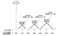
- the cluster pattern that maximizes user throughput is different for each transmission parameter.
- modulation levels QPSK, 16 QAM, 64 QAM
- FIGS. 3A and 3B the cluster pattern of the C-SC-FDMA signal (here, The relationship between the number of clusters or the cluster interval) and the user throughput is shown.
- the cluster pattern here, the number of clusters or the cluster interval
- the cluster pattern that maximizes user throughput is different for each modulation level.
- the fact that the cluster pattern that maximizes user throughput differs for each modulation level is considered to be caused by the difference in tolerance to ISI (permissible ISI) for each modulation level. That is, base station 100 and terminal 200 set the arrangement of C-SC-FDMA signal (a plurality of clusters) in the frequency domain based on a cluster pattern in consideration of allowable ISI for each different transmission parameter. User throughput can be improved.
- the modulation level was demonstrated as an example in FIG. 3A and FIG. 3B, the same may be said of other transmission parameters (coding size and coding rate).
- scheduler 112 of base station 100 determines the cluster pattern of the C-SC-FDMA signal according to the transmission parameter (MCS set or coding size) set in the C-SC-FDMA signal from terminal 200. Do.
- setting section 211 of terminal 200 sets the C-SC-FDMA signal (a plurality of C-SC-FDMA signals according to the cluster pattern according to the transmission parameter (MCS set or coding size) set to the C-SC-FDMA signal transmitted by the own terminal. Set the placement of the cluster in the frequency domain. The method of setting the cluster arrangement 1-1 to 1-6 will be described below.
- C-SC-FDMA allows setting section 211 to make ISI smaller as the modulation level set in the C-SC-FDMA signal transmitted by the own terminal is higher (the resistance to ISI is smaller). It is preferable to set the arrangement of the signal (multiple clusters) in the frequency domain.
- the number of clusters of C-SC-FDMA signals increases, the number of discontinuities in equivalent channel gain fluctuation at junctions of a plurality of clusters increases. ISI will be larger.
- the greater the number of clusters of C-SC-FDMA signals the greater the ISI.
- the smaller the number of clusters in the C-SC-FDMA signal the smaller the ISI.
- the setting unit 211 has a cluster pattern in which the number of clusters (the number of clusters per unit bandwidth) is smaller as the modulation level indicated by the MCS set set in the signal transmitted by the own terminal is higher. Divide the signal (SC-FDMA signal) according to That is, scheduler 112 determines a cluster pattern indicating a smaller number of clusters as the modulation level indicated in the MCS set set in the signal transmitted by terminal 200 is higher.
- the setting unit 211 may divide the signal (SC-FDMA signal) according to a cluster pattern with a larger cluster size, as the modulation level indicated in the MCS set set to the signal transmitted by the own terminal is higher. . That is, the scheduler 112 may determine a cluster pattern indicating a wider cluster size as the modulation level indicated in the MCS set set for the signal transmitted by the terminal 200 is higher.
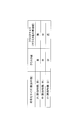
- the scheduler 112 of the base station 100 reduces the number of clusters as the modulation level is higher (makes the cluster size wider). Specifically, as shown in FIG. 4, the scheduler 112 increases the number of clusters (makes the cluster size narrower) in QPSK with a low modulation level. Also, as shown in FIG. 4, the scheduler 112 reduces the number of clusters in 64 QAM with a high modulation level (makes the cluster size wider). That is, the scheduler 112 determines a cluster pattern to be the number of clusters (high, medium, low) or cluster size (narrow, medium, wide) according to the modulation level (low, medium, high). Then, base station 100 notifies terminal 200 of spectrum division information including the determined cluster pattern (number of clusters or cluster size) and frequency resource information.
- division section 212 of setting section 211 of terminal 200 causes the SC-FDMA signal (spectrum) input from DFT section 210 to a plurality of clusters according to the cluster pattern (number of clusters or cluster size) determined by scheduler 112.
- the division unit 212 uses the SC-FDMA signal according to a cluster pattern in which the number of clusters is smaller (or the cluster size is larger) as the modulation level indicated in the MCS set set in the signal transmitted by the own terminal is higher.
- the mapping unit 213 of the setting unit 211 maps a plurality of clusters to discontinuous frequency resources based on the frequency resource information.
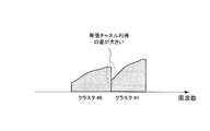
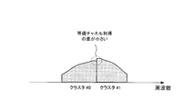
- the scheduler 112 increases the number of clusters as shown in FIG. 5A (four clusters # 0 to # 3 in FIG. 5A), that is, Determine the cluster pattern (number of clusters or cluster size) so that the cluster size per cluster becomes narrow. Then, the dividing unit 212 divides the SC-FDMA signal (spectrum) into four clusters of clusters # 0 to # 3 as shown in FIG. 5A, and the mapping unit 213 divides the four clusters # 0 to # 3. Map to discontinuous frequency resources respectively. As a result, as shown in FIG. 5A, a C-SC-FDMA signal having a large number of clusters (narrow cluster size) is generated.
- the scheduler 112 reduces the number of clusters (two clusters # 0 and # 1 in FIG. 5B), that is, Determine the cluster pattern (number of clusters or cluster size) so that the cluster size becomes wider. Then, division section 212 divides the SC-FDMA signal (spectrum) into two clusters of cluster # 0 and cluster # 1 as shown in FIG. 5B, and mapping section 213 divides cluster # 0 and cluster # 1. Map to discontinuous frequency resources respectively. As a result, as shown in FIG. 5B, a C-SC-FDMA signal with a small number of clusters (a large cluster size) is generated.
- terminal 200 transmits the C-SC-FDMA signal shown in FIG. 5A (in the case of modulation scheme: QPSK) or FIG. 5B (in the case of modulation scheme: 64 QAM) to base station 100, and base station 100 receives the signal.
- An equalization process is performed on the C-SC-FDMA signal, and the equalized C-SC-FDMA signal (a plurality of clusters) is combined.
- a signal after cluster combination as shown in FIG. 6A (modulation scheme: in the case of QPSK) or FIG. 6B (modulation scheme: in the case of 64 QAM) is obtained.
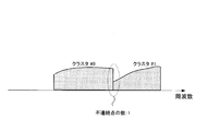
- the number of discontinuities in the variation of the equivalent channel gain in the combined signal is three.
- the modulation level is higher (in the case of modulation scheme: 64 QAM)
- the number of discontinuities in fluctuation of equivalent channel gain in the combined signal is one. That is, as shown in FIGS. 6A and 6B, the higher the modulation level, the fewer the number of discontinuities in the variation of the equivalent channel gain in the combined signal. That is, the higher the modulation level, the smaller the ISI generated at the connection points (discontinuous points) of the plurality of clusters.
- the modulation level is higher, that is, the Euclidean distance between signal points is shorter and the tolerance to ISI (permissible ISI) is smaller, the number of clusters of C-SC-FDMA signal is smaller ( Or make the cluster size wider). This makes it possible to further reduce ISI for the C-SC-FDMA signal.
- the modulation level is lower, that is, if the Euclidean distance between signal points is longer and the tolerance to ISI (permissible ISI) is larger, the number of clusters of C-SC-FDMA signal is increased (cluster size Make it narrower). This can improve the frequency diversity effect by mapping more clusters to multiple frequency resources with different channel variations.
- the modulation level is lower, the number of discontinuities in the variation of equivalent channel gain in the combined signal is larger (ie, ISI is larger).
- the modulation level since the lower the modulation level, the greater the tolerance to ISI (permissible ISI), the influence of ISI on the transmission characteristics is small.
- the terminal divides the SC-FDMA signal by the number of clusters (or cluster size) according to the modulation level indicated in the MCS set.
- the higher the modulation level the smaller the allowable ISI
- the smaller the number of clusters of C-SC-FDMA signal by the terminal the number of junctions (discontinuities) of clusters is reduced.
- ISI can be reduced.
- the lower the modulation level the larger the allowable ISI
- this setting method it is possible to improve the transmission characteristics according to the modulation level, and therefore the system by C-SC-FDMA (by clustering SC-FDMA signals) at any modulation level. It is possible to improve the user throughput at each terminal while maintaining the improvement effect of the throughput.
- ISI can be controlled by determining the number of clusters (cluster size) according to the modulation level. Therefore, for example, when adaptive modulation and channel coding (AMC) control is used, the base station controls the ISI by determining the number of clusters (cluster size) according to the modulation level. It is possible to estimate the instantaneous ISI in advance. Therefore, the base station is likely to be able to select an accurate MCS set according to the instantaneous reception quality (for example, the instantaneous SINR) in consideration of the influence of the instantaneous ISI. Therefore, according to this setting method, the number of retransmissions due to a transmission error can be reduced by selecting the correct MCS set, and thus the user throughput can be further improved.
- AMC adaptive modulation and channel coding
- ⁇ Setting method 1-2> Although setting method 1 described the case where the setting unit 211 divides the SC-FDMA signal by the number of clusters according to the modulation level indicated in the MCS set set in the C-SC-FDMA signal, this setting method The setting unit 211 maps a plurality of clusters to frequency resources at cluster intervals according to the modulation level set in the C-SC-FDMA signal.
- MMSE minimum mean square error
- the difference in equivalent channel gain (power difference and amplitude difference, phase difference if there is a channel estimation error) at the junction point (discontinuous point) of multiple clusters constituting the C-SC-FDMA signal becomes larger, ISI becomes larger. That is, the wider the cluster spacing of the C-SC-FDMA signal, the larger the ISI. In other words, the narrower the cluster spacing of the C-SC-FDMA signal, the smaller the ISI.
- the setting unit 211 sets the signal (SC-FDMA signal) in accordance with the cluster pattern in which the cluster interval is narrower as the modulation level indicated in the MCS set set in the signal transmitted by the own terminal is higher. , And mapping to a plurality of discontinuous frequency resources. That is, scheduler 112 determines a cluster pattern indicating a narrower cluster interval as the modulation level indicated in the MCS set set for the signal transmitted by terminal 200 is higher.
- the number of clusters is 2 (cluster # 0 and cluster # 1 shown in FIGS. 8A and 8B).
- the setting method 1-1 as shown in FIG. 7, the case where QPSK (modulation level: low), 16 QAM (modulation level: middle), and 64 QAM (modulation level: high) will be described as modulation schemes. .
- the bandwidths of the C-SC-FDMA signal in FIG. 8A and FIG. 8B are the same.
- the scheduler 112 of the base station 100 makes the cluster interval narrower as the modulation level is higher. Specifically, as shown in FIG. 7, the scheduler 112 makes the cluster interval wider in QPSK with low modulation level. Also, as shown in FIG. 7, the scheduler 112 makes the cluster interval narrower for 64 QAM with a high modulation level. That is, the scheduler 112 determines a cluster pattern to be a cluster interval (wide, medium, narrow) according to the modulation level (low, medium, high). Then, the base station 100 notifies the terminal 200 of frequency resource information including spectrum division information (for example, the number of clusters: 2) and the determined cluster pattern (cluster interval).
- spectrum division information for example, the number of clusters: 2
- division section 212 of setting section 211 of terminal 200 divides the SC-FDMA signal (spectrum) input from DFT section 210 into two clusters according to spectrum division information (here, the number of clusters: 2). Do. Also, the mapping unit 213 of the setting unit 211 maps the two clusters on discontinuous frequency resources according to the cluster pattern (cluster interval) determined by the scheduler 112. That is, mapping section 213 sets a plurality of clusters to a plurality of discontinuous frequency resources according to a cluster pattern in which the cluster interval is narrower as the modulation level indicated in the MCS set set in the signal transmitted by the own terminal is higher.
- Maps maps the two clusters on discontinuous frequency resources according to the cluster pattern (cluster interval) determined by the scheduler 112. That is, mapping section 213 sets a plurality of clusters to a plurality of discontinuous frequency resources according to a cluster pattern in which the cluster interval is narrower as the modulation level indicated in the MCS set set in the signal transmitted by the own terminal is higher.
- mapping section 213 shows two clusters of cluster # 0 and cluster # 1 generated by dividing the SC-FDMA signal (spectrum) by division section 212 in a cluster pattern. Map each to discontinuous frequency resources separated by a frequency interval.
- a C-SC-FDMA signal with a wide frequency interval between cluster # 0 and cluster # 1 is generated.
- the scheduler 112 determines a cluster pattern (cluster interval) such that the cluster interval becomes narrow, as shown in FIG. 8B.
- mapping section 213 shows two clusters of cluster # 0 and cluster # 1 generated by dividing the SC-FDMA signal (spectrum) by division section 212 in a cluster pattern. Map each to discontinuous frequency resources separated by a frequency interval.
- a C-SC-FDMA signal with a narrow frequency interval between cluster # 0 and cluster # 1 is generated.
- terminal 200 transmits the C-SC-FDMA signal shown in FIG. 8A (in the case of modulation scheme: QPSK) or FIG. 8B (in the case of modulation scheme: 64 QAM) to base station 100. Therefore, in the base station 100, a signal after cluster combination as shown in FIG. 9A (modulation scheme: in the case of QPSK) or FIG. 9B (modulation scheme: in the case of 64 QAM) is obtained.
- the cluster spacing of the C-SC-FDMA signal is made narrower. This makes it possible to reduce the ISI for the C-SC-FDMA signal as in the case of the setting method 1-1 (when reducing the number of clusters).
- the modulation level is lower, that is, the tolerance to ISI (tolerable ISI) is larger, the cluster spacing of the C-SC-FDMA signal is made wider. This can improve the frequency diversity effect by mapping a plurality of clusters to more distant frequency resources.
- the modulation level is lower, in order to make the cluster interval constituting the C-SC-FDMA signal wider, as shown in FIG. The difference is greater (ie, ISI is greater).
- the tolerance to ISI permissible ISI
- the terminal maps a plurality of clusters to frequency resources at cluster intervals according to the modulation level indicated in the MCS set.
- the higher the modulation level the smaller the allowable ISI
- the narrower the inter-cluster spacing of the C-SC-FDMA signal by the terminal by increasing the channel frequency correlation between multiple clusters
- ISI can be reduced.
- the lower the modulation level the larger the allowable ISI
- ISI can be reduced by determining the cluster interval according to the modulation level. Therefore, as in the setting method 1-1, when AMC control is used, the base station estimates the instantaneous ISI in advance by determining the cluster interval according to the modulation level and controlling the ISI. be able to. Therefore, the base station selects an accurate MCS set according to instantaneous reception quality (for example, instantaneous SINR) in consideration of the influence of instantaneous ISI, so that the number of retransmissions due to transmission errors can be reduced, and user throughput can be further reduced. Can be improved.
- instantaneous SINR instantaneous SINR
- the setting unit 211 divides the SC-FDMA signal by the number of clusters (division number) according to the coding size (code block size) set in the C-SC-FDMA signal.
- C-SC is configured such that setting section 211 makes ISI smaller as the coding size set in the C-SC-FDMA signal transmitted by the own terminal is smaller (or as the number of RBs allocated is smaller). It is preferable to set the arrangement of the FDMA signal (multiple clusters) in the frequency domain.
- the setting unit 211 decreases the number of clusters (the number of clusters per unit bandwidth) as the coding size set for the signal transmitted by the own terminal decreases (as the number of allocated RBs decreases). Divide the signal (SC-FDMA signal) according to the lesser cluster pattern. That is, the scheduler 112 determines a cluster pattern indicating a smaller number of clusters as the coding size set in the signal transmitted by the terminal 200 is smaller. Note that the setting unit 211 follows the cluster pattern in which the cluster size is wider as the coding size set for the signal transmitted by the own terminal is smaller (or the number of RBs allocated is smaller), as in the allocation method 1-1. , Signals (SC-FDMA signal) may be divided.
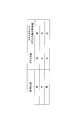
- the scheduler 112 makes the number of clusters smaller (makes the cluster size wider) as the coding size is smaller (as the number of RBs allocated is smaller). Specifically, as shown in FIG. 10, scheduler 112 determines the number of clusters (large, medium, small) according to the coding size (large, medium, small) (or the number of allocated RBs (large, medium, small)). Determine a cluster pattern to be small (or small) (or narrow, medium, wide). Then, base station 100 notifies terminal 200 of spectrum division information including the determined cluster pattern (number of clusters or cluster size) and frequency resource information.
- the scheduler 112 increases the number of clusters as shown in FIG. 11A as in the setting method 1-1 (FIG. 5A) (FIG. 11A). Then, the cluster pattern (the number of clusters or the cluster size) is determined so that the six clusters # 0 to # 5), that is, the cluster size per cluster becomes narrow.
- the scheduler 112 reduces the number of clusters as shown in FIG. 11B as in the setting method 1-1 (FIG. 5B) (FIG. 11B Then, two clusters # 0 and # 1), that is, a cluster pattern (the number of clusters or the cluster size) are determined so that the cluster size becomes wide.
- the dividing unit 212 of the setting unit 211 divides the SC-FDMA signal (spectrum) into a plurality of clusters based on the number of clusters (or cluster size) indicated in the cluster pattern, as shown in FIG. 11A or 11B. Do. That is, division section 212 follows the cluster pattern in which the number of clusters is smaller (or the cluster size is larger) as the coding size set for the signal transmitted by the own terminal is smaller (as the number of allocated RBs is smaller). Split the signal. Then, the mapping unit 213 maps the plurality of clusters to discontinuous frequency resources based on the frequency resource information.
- the C-SC-FDMA signal is the same as in the setting method 1-1.
- Increase the number of clusters make the cluster size smaller.
- base station 100 increases the number of discontinuities of equivalent channel gain fluctuation in the combined signal, but performs error correction decoding with a large coding size to suppress the influence of allowable ISI.
- a larger coding gain can be obtained.
- the setting method 1-1 even when the terminal divides the SC-FDMA signal by the number of clusters (the number of divisions) according to the coding size (or the number of allocated RBs), the setting method 1-1 and Similarly, for any coding size, the user throughput at each terminal can be improved while maintaining the improvement effect of the system throughput by C-SC-FDMA (that is, by clustering SC-FDMA signals). it can.
- setting section 211 sets the signal (SC ⁇ ) according to the cluster pattern with a narrower cluster interval as the coding size set for the signal transmitted by the own terminal decreases (as the number of allocated RBs decreases).
- the FDMA signal is mapped to discrete frequency resources respectively. That is, scheduler 112 determines a cluster pattern indicating a narrower cluster interval as the coding size set for the signal transmitted by terminal 200 is smaller (or as the number of RBs allocated is smaller).
- the number of clusters is 2 (cluster # 0 and cluster # 1).
- the setting method 1-3 FIG. 10
- the case of using the encoding size (large, medium, small) (or the number of allocated RBs (many, medium, small)) will be described.
- the MCS set (coding rate and modulation level) set for the C-SC-FDMA signal is constant.
- the scheduler 112 makes the cluster interval narrower as the coding size is smaller (as the number of RBs allocated is smaller). Specifically, as shown in FIG. 12, scheduler 112 sets the cluster interval (wide, medium) according to the coding size (large, medium, small) (or the number of allocated RBs (many, medium, small)). , Narrow) to determine the cluster pattern. Then, the base station 100 notifies the terminal 200 of frequency resource information including spectrum division information (for example, the number of clusters: 2) and the determined cluster pattern (cluster interval).
- spectrum division information for example, the number of clusters: 2
- the scheduler 112 uses a cluster pattern (the cluster interval is wide as shown in FIG. 13A). Determine the cluster interval).
- the scheduler 112 uses cluster patterns (clusters (clusters) so that the cluster spacing becomes narrow as in the setting method 1-2 (FIG. 8B). Determine the interval).
- the dividing unit 212 of the setting unit 211 sets the SC-FDMA signal (spectrum) to the cluster # 0 and the cluster as shown in FIG. 13A or FIG. 13B based on the spectrum division information (here, the number of clusters: 2). Divide into two clusters # 1. Further, as shown in FIG. 13A or 13B, the mapping unit 213 of the setting unit 211 sets two clusters of cluster # 0 and cluster # 1 as discontinuous frequency resources based on the cluster interval shown in the cluster pattern. Map to each That is, mapping section 213 sets a plurality of discontinuous clusters according to a cluster pattern having a narrower cluster interval as the coding size set for the signal transmitted by the own terminal is smaller (as the number of allocated RBs is smaller). Map to frequency resources respectively.
- C-SC- make the cluster spacing of the FDMA signal narrower.
- the frequency correlation between clusters here, between cluster # 0 and cluster # 1 becomes high. Therefore, the ISI for C-SC-FDMA signal should be smaller because the variation of equivalent channel gain becomes slower (that is, the difference between equivalent channel gains becomes smaller) at cluster junctions (discontinuous points).
- the C-SC-FDMA signal is set as in the setting method 1-2.
- the cluster interval wider. This reduces the frequency correlation between clusters (here, between cluster # 0 and cluster # 1) (although the fluctuation of equivalent channel gain at cluster junctions (discontinuous points) becomes sharp), but the code
- a larger coding gain can be obtained by improving the frequency diversity effect while suppressing the influence of allowable ISI.
- the setting unit 211 divides the SC-FDMA signal by the number of clusters (number of divisions) according to the coding rate indicated in the MCS set set in the C-SC-FDMA signal.
- the setting unit 211 decreases the number of clusters (the number of clusters per unit bandwidth) as the coding rate indicated by the MCS set set in the signal transmitted by the own terminal increases.
- Divide the signal (SC-FDMA signal) according to the pattern. That is, scheduler 112 determines a cluster pattern indicating a smaller number of clusters as the coding rate indicated in the MCS set set in the signal transmitted by terminal 200 is higher.
- setting section 211 follows the cluster pattern having a wider cluster size as the coding rate indicated in the MCS set set in the signal transmitted by the own terminal increases.
- FDMA signal may be divided.
- the scheduler 112 reduces the number of clusters as the coding rate is higher (makes the cluster size wider). Specifically, as shown in FIG. 14, the scheduler 112 determines the number of clusters (high, medium, low) (or cluster size (narrow, medium, wide) according to the coding rate (low, medium, high). Determine the cluster pattern to be). Then, base station 100 notifies terminal 200 of spectrum division information including the determined cluster pattern (number of clusters or cluster size) and frequency resource information.
- the scheduler 112 when the coding rate is low, the scheduler 112 performs the cluster pattern (the number of clusters so that the number of clusters increases, that is, the cluster size for each cluster becomes narrow, as in the setting method 1-3 (FIG. 11A) Or determine the cluster size).
- the scheduler 112 uses the cluster pattern (the number of clusters or the cluster size so that the number of clusters decreases, that is, the cluster size becomes wide, as in the setting method 1-3 (FIG. 11B) To determine).
- the division unit 212 of the setting unit 211 divides the SC-FDMA signal (spectrum) into a plurality of clusters based on the number of clusters (or the cluster size) indicated in the cluster pattern. That is, division section 212 divides the signal according to a cluster pattern with a smaller number of clusters (or a larger cluster size) as the coding rate indicated in the MCS set set in the signal transmitted by the own terminal is higher. Do. Then, the mapping unit 213 of the setting unit 211 maps a plurality of clusters to discontinuous frequency resources based on the frequency resource information.
- the higher the coding rate that is, the smaller the tolerance to ISI (permissible ISI)
- ISI for the C-SC-FDMA signal can be made smaller.
- the coding rate is lower, that is, as the resistance to ISI (permissible ISI) is larger, the number of clusters of C-SC-FDMA signal is increased (the cluster size is narrowed). Similar to 1, by performing error correction decoding with a low coding rate, it is possible to improve the frequency diversity effect while suppressing the influence of allowable ISI.
- ISI can be controlled by determining the number of clusters (size) according to the coding rate. Therefore, as in the case of setting method 1-1, when AMC control is used, the base station determines the number of clusters (size) according to the coding rate to control ISI, thereby enabling instantaneous ISI. Can be estimated in advance. Therefore, the base station selects an accurate MCS set according to instantaneous reception quality (for example, instantaneous SINR) in consideration of the influence of instantaneous ISI, so that the number of retransmissions due to transmission errors can be reduced, and user throughput can be further reduced. Can be improved.
- instantaneous SINR instantaneous SINR
- setting section 211 sets a plurality of clusters forming C-SC-FDMA signal at frequency intervals of clusters according to the coding rate indicated by the MCS set set in C-SC-FDMA signal.
- the setting unit 211 sets the signal (SC-FDMA signal) according to the cluster pattern with a narrower cluster interval, as the coding rate indicated in the MCS set set in the signal transmitted by the own terminal is higher.
- SC-FDMA signal SC-FDMA signal
- Scheduler 112 determines a cluster pattern indicating a narrower cluster interval as the coding rate indicated in the MCS set set for the signal transmitted by terminal 200 is higher.
- the number of clusters is two.
- the setting method 1-5 (FIG. 14), as shown in FIG. 15, the case of using the coding rate (low, medium, high) will be described.
- the coding size and the modulation level are constant.
- the scheduler 112 makes the cluster interval narrower as the coding rate is higher. Specifically, as shown in FIG. 15, the scheduler 112 determines a cluster pattern to be a cluster interval (wide, medium, narrow) according to the coding rate (low, medium, high). Then, the base station 100 notifies the terminal 200 of frequency resource information including spectrum division information (for example, the number of clusters: 2) and the determined cluster pattern (cluster interval).
- spectrum division information for example, the number of clusters: 2
- the scheduler 112 determines a cluster pattern (cluster interval) so that the cluster interval is wide, as in the setting method 1-4 (FIG. 13A).
- the scheduler 112 determines a cluster pattern (cluster interval) so that the cluster interval becomes narrow, as in the setting method 1-4 (FIG. 13B).
- the division unit 212 of the setting unit 211 divides the SC-FDMA signal (spectrum) into a plurality of clusters based on the spectrum division information.
- the mapping unit 213 of the setting unit 211 maps a plurality of clusters to discontinuous frequency resources based on the cluster interval shown in the cluster pattern. That is, mapping section 213 maps a plurality of clusters on a plurality of discontinuous frequency resources according to a cluster pattern in which the cluster interval is narrower as the coding rate set for the signal transmitted by the own terminal is higher.
- the cluster spacing of the C-SC-FDMA signal is made narrower, as in the setting method 1-2.
- the ISI for SC-FDMA signals can be made smaller.
- the coding is performed in the same manner as in setting method 1-2, by making the cluster interval constituting the C-SC-FDMA signal wider.
- any coding rate is used.
- the user throughput at each terminal can be improved while maintaining the improvement effect of the system throughput (by clustering SC-FDMA signals) by C-SC-FDMA.
- ISI can be controlled by determining the cluster interval in accordance with the coding rate. Therefore, when AMC control is used in the same manner as in setting method 1-2, the base station determines the cluster interval according to the coding rate and controls ISI in advance to control instantaneous ISI. It can be estimated. Therefore, the base station selects an accurate MCS set according to instantaneous reception quality (for example, instantaneous SINR) in consideration of the influence of instantaneous ISI, so that the number of retransmissions due to transmission errors can be reduced, and user throughput can be further reduced. Can be improved.
- instantaneous SINR instantaneous SINR
- the terminal divides the SC-FDMA signal (spectrum) into a plurality of clusters according to the MCS pattern (modulation level, coding rate) or the cluster pattern according to the coding size. , And multiple clusters are mapped to discrete frequency resources respectively.
- the terminal can set the arrangement of multiple clusters in the frequency domain according to the difference in tolerance to ISI (permissible ISI) for each transmission parameter.
- the SC-FDMA signal is divided into a plurality of clusters and the plurality of clusters are mapped to discontinuous frequency bands, that is, even when C-SC-FDMA is used, Since transmission characteristics can be improved for each terminal for which different transmission parameters are set, it is possible to improve user throughput while maintaining the improvement effect of system throughput.
- base station 100 may set a threshold to determine a cluster pattern.
- the base station 100 can determine the cluster pattern by comparing the transmission parameter (modulation level, coding rate or coding size) set for each terminal with the threshold.
- each terminal can easily perform division processing of the SC-FDMA signal (spectrum) and mapping processing of the C-SC-FDMA signal (a plurality of clusters).
- SC-FDMA signal spectrumrum
- mapping processing of the C-SC-FDMA signal a plurality of clusters.
- the base station 100 may set the threshold to the modulation level to determine the cluster pattern. For example, as shown in FIG. 16A, base station 100 sets a threshold so as to divide a plurality of modulation levels into a range of modulation levels, and sets the modulation level (A) and the threshold set for each terminal.
- the number of clusters (X) may be determined by comparison. Specifically, in FIG. 16A, the base station 100 determines the number X of clusters to be four when the modulation level (A) is BPSK to QPSK, and the number of clusters when the modulation level (A) is 8 PSK to 16 QAM.
- X is determined to be 3 and the modulation level (A) is 32QAM to 64QAM, the number of clusters X is determined to 2; if the modulation level (A) is 128QAM to 256QAM, the number of clusters X is determined to be 1 Do. That is, in FIG. 16A, a fixed number of clusters is determined for a certain range of modulation levels.
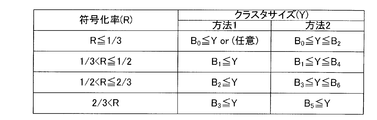
- the base station 100 may set the lower limit and the upper limit of the number of clusters X for each modulation level. For example, as shown in method 2 of FIG. 16B, when the modulation level (A) is BPSK, the base station 100 determines the number of clusters in any range of 2 ⁇ X ⁇ 4, and the modulation level (A) is In the case of 16 QAM, the number of clusters in any range of 1 ⁇ X ⁇ 2 is determined. Thereby, for example, as illustrated in FIG. 3A or 3B, the setting unit 211 of each terminal can set only the number of clusters X in which the user throughput is equal to or more than a certain value including the maximum value. Further, since the range of the cluster number X is limited for each modulation level, the base station 100 can reduce the number of notification bits for notifying the cluster number X.
- the base station 100 sets a threshold value to divide a plurality of modulation levels into a range of modulation levels, and sets a cluster size (Y) for each range of modulation levels. May be In the method 1 of FIG. 16C, as in the method 1 of FIG. 16B, the base station 100 determines the minimum cluster size defined for each modulation level in each range (B 0 , B 1 , B 2 shown in the method 1 of FIG. , B 3 ) is determined as one of the cluster sizes Y. Note that, as shown in method 1 of FIG.
- the base station 100 determines the cluster size Y to an arbitrary value. May be In addition, in the method 2 of FIG. 16C, as in the method 2 of FIG. 16B, the upper limit and the lower limit of the cluster size Y are set for each modulation level in each range.
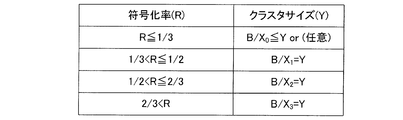
- the base station 100 calculates the cluster size (Y) using the number of clusters (X), as shown in FIG. 16D, the base station 100 sets a threshold for each modulation level, and for each modulation level
- the cluster size Y may be calculated by setting the cluster number Xa to.
- B indicates the total bandwidth (that is, the sum of each cluster size) used for the C-SC-FDMA signal.
- the base station 100 sets a threshold so as to divide a plurality of modulation levels into each of a range of modulation levels, and sets a cluster interval (Z) for each of the modulation levels in each range.
- the base station 100 determines the cluster interval Z up to the maximum cluster interval (B ′ 0 , B ′ 1 , B ′ 2 , B ′ 3 shown in FIG. 16E) for each modulation level in each range.
- the base station 100 may set the cluster interval Z to an arbitrary value.
- the base station 100 may set a threshold for the coding size to determine a cluster pattern. For example, as shown in FIG. 17A, the base station 100 sets a threshold so as to divide the coding size into a certain range of coding sizes, and sets the coding size (N) and the threshold set for each terminal. To determine the number of clusters (X). Specifically, in FIG. 17A, the base station 100 determines the cluster number X to be one when the coding size N is 100 bits or less, and the cluster when the coding size N is 101 bits or more and 500 bits or less. Determine the number X as two. The same applies to the case where the coding size N is 501 bits or more and 1000 bits or less and the case where the coding size N is 1001 bits or more.
- the base station 100 may set a cluster size (Y) for each coding size in each range.
- the base station 100 determines the minimum cluster size defined for each encoding size of each range (B 0 , B 1 , B shown in the method 1 of FIG. 2. Determine any cluster size Y with 2 and B 3 ) as the lower limits.
- the base station 100 may determine the cluster size Y to an arbitrary value.
- the base station 100 may set the lower limit and the upper limit of the cluster size Y for each coding size in each range, as in the method 2 of FIG. 16C.
- the base station 100 calculates the cluster size (Y) using the number of clusters (X), as shown in FIG. 17C, the base station 100 encodes each range as in FIG. 16D.
- the number of clusters X n may be set for each size, and the cluster size Y may be calculated.
- the base station 100 may set a cluster interval (Z) for each coding size of each range.
- the base station 100 sets the maximum cluster interval (B ′ 0 , B ′ 1 , B ′ 2 , B ′ 3 shown in FIG. 17D) as the upper limit for each encoding size in each range. Determine the cluster interval.
- the base station 100 may set the cluster interval (Z) to an arbitrary value in the range where the coding size (N) is 1001 bits or more.
- the base station 100 may set a threshold for the coding rate to determine a cluster pattern. For example, as shown in FIG. 18A, the base station 100 sets a threshold so as to divide the coding rate into a range of coding rates, and sets the coding rate (R) and the threshold set for each terminal. To determine the number of clusters (X). Specifically, in FIG. 18A, when the coding rate R is 1/3 or less, the base station 100 determines the number of clusters X to be four, and the coding rate R is greater than 1/3 and 1/2 or less. In the case of, the number of clusters X is determined to be three. The same applies to the case where the coding rate R is greater than 1/2 and not more than 2/3 and the case where the coding rate R is greater than 2/3.
- the base station 100 may set the cluster size Y to an arbitrary value in the range where the coding rate R is 100 bits or less.
- the base station 100 may set a cluster interval (Z) for each coding rate in each range.
- the base station 100 sets the maximum cluster interval (B ′ 0 , B ′ 1 , B ′ 2 , B ′ 3 shown in FIG. 18D) as the upper limit for each coding rate in each range. Determine the cluster interval (Z).
- the base station 100 may set the cluster interval (Z) to an arbitrary value in the range where the coding rate (R) is 1/3 or less.
- the base station 100 may determine a cluster pattern by combining a plurality of transmission parameters (modulation level, coding rate and coding size). For example, the base station 100 may determine the cluster pattern according to the combination of the modulation level and the coding rate, that is, the MCS set. For example, in the case of using AMC control that simultaneously controls the modulation level and the coding rate, the base station 100 can simultaneously control the resistance to ISI caused by both the modulation level and the coding rate. For example, as shown in FIG.
- FIG. 19 has described the case where the cluster pattern is determined without considering SINR (or average SNR), but in the present invention, in accordance with the variation of SINR (or average SNR), FIG. The correspondence of FIG. 19 may be changed.
- the terminal 200 when terminal 200 multiplexes a plurality of codewords (coding unit, codeword: CW) in the frequency domain and transmits the result to base station 100, base station 100 transmits
- the cluster pattern may be determined for each CW transmitted from the terminal 200.
- CW # 1 to CW # (M-1) are multiplexed in the frequency domain and transmitted
- the terminal 200 uses a division unit provided for each CW to generate a plurality of CWs.
- the cluster for each CW is frequency-multiplexed by the mapping unit.
- the terminal 200 should have a smaller number of clusters (a larger cluster size) or narrower cluster intervals the higher the transmission rate of CWs.
- the arrangement in the frequency domain of a plurality of clusters constituting CW may be set.
- the base station 100 determines a cluster pattern (number of clusters, cluster size, or cluster interval) and notifies cluster pattern to terminal 200 has been described.
- the base station 100 notifies only the frequency resource information to the terminal 200 each time communication with the terminal 200 is performed, and the terminal 200 transmits a cluster pattern (cluster) according to the transmission parameter of the signal transmitted by the own terminal. Number, cluster size, or cluster interval) may be determined.
- the base station 100 may notify the terminal 200 of frequency resource information indicating a frequency band allocated in consideration of the number of clusters, the cluster size, and the cluster interval. Specifically, the base station 100 (the scheduler 112 of the base station 100) performs allocation processing for allocating a frequency band to the terminal 200 that exhibits the maximum SINR in a certain frequency band (subcarrier) by performing scheduling. The base station 100 performs frequency resource allocation of a C-SC-FDMA signal composed of a plurality of clusters by repeatedly performing the above allocation process in different frequency bands. Then, base station 100 notifies terminal 200 of frequency resource information indicating the result of frequency resource allocation of the C-SC-FDMA signal of terminal 200.
- the base station 100 performs the above-mentioned frequency resource allocation process also for other terminals than the terminal 200.
- base station 100 can schedule frequency resource allocation to all terminals located in its own cell.
- the terminal 200 may map the SC-FDMA signal according to the frequency band indicated in the frequency resource information notified from the base station 100.
- the SC-FDMA signal is divided into a plurality of clusters according to the cluster pattern according to the transmission parameter of the signal transmitted by the own terminal, and the plurality of clusters are mapped to discontinuous frequency resources respectively. The same effect as that of the present embodiment can be obtained.
- MIMO multi-input multi-output
- a plurality of antennas are provided in both a base station and a terminal, a plurality of propagation paths (streams) are prepared in the space between radio transmission and reception on the same time and the same frequency resource, and each stream is spatially Throughput can be increased by multiplexing (transmitting different data signal sequences using multiple streams).
- C-SC-FDMA also generates ISI for each layer as described in the first embodiment.
- the terminal in order to reduce ISI between layers, the terminal preferably makes ISI for each layer smaller as in the first embodiment as the Rank number during MIMO transmission increases. Therefore, the terminal according to the present embodiment divides CW (code word), which is an SC-FDMA signal, into a plurality of clusters according to a cluster pattern according to the Rank number at the time of MIMO transmission, and discontinuouss the plurality of clusters. Map each in the frequency domain.
- CW code word
- the configuration of terminal 300 according to the present embodiment is shown in FIG.
- the terminal 300 comprises M antennas (antennas 201-1 and 201 -M) that transmit CW (multiple clusters) using M streams.
- the terminal 300 corresponds to the number N of C-SC-FDMA processing units 301-1 to 301-N including the encoding unit 207, the modulation unit 208, the multiplexing unit 209, the DFT unit 210, and the dividing unit 212.
- terminal 300 includes transmission processing sections 303-1 to 303-M including mapping section 213, IFFT section 214, CP insertion section 215, and wireless transmission section 216 corresponding to antennas 201-1 to 201-M. Therefore, the terminal 300 includes the setting unit 211 configured of N division units 212 and M mapping units 213. Also, N and M satisfy the relationship of N ⁇ M.
- the C-SC-FDMA processing units 301-1 to 301 -N perform the same processes as the coding unit 207 to the division unit 212 of the first embodiment on the transmission bit sequence (CW) input thereto. Thus, C-SC-FDMA signal (multiple clusters) is generated. Then, the C-SC-FDMA processing units 301-1 to 301-2 output the generated C-SC-FDMA signal to the precoding unit 302.
- a precoding matrix (Precoding Matrix or precoding weight) is input to the precoding unit 302 from the control unit 206.
- precoding information indicating the precoding matrix is notified to terminal 300 from a base station (not shown).
- the precoding information may indicate a number indicating each precoding matrix, and the control unit 206 may calculate each precoding matrix based on the number indicated in the precoding information.
- the precoding unit 302 multiplies the C-SC-FDMA signal input from each of the C-SC-FDMA processing units 301-1 to 301-N by a precoding matrix. Then, precoding section 302 outputs the C-SC-FDMA signal after precoding to transmission processing sections 303-1 to 303-M corresponding to each stream.
- Transmission processing sections 303-1 to 303 -M perform the same processing as mapping section 213 to radio transmission section 216 in the first embodiment on the pre-coded C-SC-FDMA signal input thereto.
- the C-SC-FDMA signal after the transmission processing is transmitted to the base station via the antennas 201-1 to 201-M.
- the setting unit 211 sets the cluster pattern input from the control unit 206, that is, the cluster pattern according to the MCS set, the coding size, or the Rank number at the time of MIMO transmission set to the signal transmitted by the own terminal.
- the SC-FDMA signal of each layer here, layer # 1 to layer #N
- the plurality of clusters are mapped to discontinuous frequency resources respectively.
- the scheduler (not shown) of the base station does not set the MCS set (modulation level and coding rate), coding size, or the like set in the C-SC-FDMA signal from each terminal.
- the cluster pattern of the C-SC-FDMA signal from each terminal is determined according to the Rank number at the time of MIMO transmission of each terminal. Then, the base station notifies each terminal of the determined cluster pattern.
- the number of antennas (the number of streams) is four, and the terminal 300 includes the antennas 201-1 to 201-4. Also, the number of CWs simultaneously transmitted by the terminal 300 is two. Further, in the following description, in order to simplify the description, for example, as shown in FIG. 23A and FIG. 23B, DFT unit 210, setting unit 211 (division unit 212 and Only the mapping unit 213), the precoding unit 302, the IFFT unit 214, and the antenna 201 are shown. For example, in FIG. 23A and FIG.
- the terminal 300 is provided with four mapping units 213 and IFFT units 214 corresponding to the number of four antennas, respectively, and the number of Ranks (for example, Number of Ranks: 2 in FIG. 23A, FIG. 23B
- the DFT unit 210 and the dividing unit 212 are provided in numbers corresponding to the number of Ranks: 4).
- FIG. 23B the terminal 300 is provided with four mapping units 213 and IFFT units 214 corresponding to the number of four antennas, respectively, and the number of Ranks (for example, Number of Ranks: 2 in FIG. 23A, FIG. 23B
- the DFT unit 210 and the dividing unit 212 are provided in numbers corresponding to the number of Ranks: 4).
- the terminal 300 (Rank number / CW number) Only one S / P (serial parallel conversion) unit is provided between the modulation unit 208 and the multiplexing unit 209 of the terminal 300 shown in FIG. Then, the S / P unit converts the CWs input in series in parallel, and distributes the converted CWs to a plurality of layers ((number of Rank / number of CW) layers) to obtain the number of Ranks. A plurality of CWs are respectively mapped to only layers. If the number of CWs, the number of Ranks, and the number of streams are the same, the terminal 300 may perform DFT processing and division processing on each CW, and map each CW on each layer.
- the setting unit 211 divides the SC-FDMA signal according to a cluster pattern in which the number of clusters is smaller (or the cluster size is larger) as the number of Ranks in MIMO transmission is larger.
- the MCS set (coding rate and modulation level) set to CW and the coding size are made constant.
- the scheduler of the base station reduces the number of clusters as the number of Ranks increases (makes the cluster size wider). Specifically, as shown in FIG. 22, the scheduler of the base station determines the number of clusters (high, medium, low) (or the cluster size (narrow, middle, small) according to the number of ranks (low, medium, high). Determine the cluster pattern to be
- the division unit 212 of the setting unit 211 divides the CW according to a cluster pattern in which the number of clusters is smaller (or the cluster size is larger) as the number of Ranks is larger. Specifically, when the number of Ranks is small (number of Ranks: 2 in FIG. 23A), the dividing unit 212 increases the number of clusters (four clusters # 0 to # 3 in FIG. 23A), that is, The CW of each layer (the number of layers in FIG. 23A: 2) is divided so that the cluster size for each cluster becomes narrow. On the other hand, when the number of Ranks is large (number of Ranks: 4 in FIG.
- the dividing unit 212 decreases the number of clusters (two clusters # 0 and # 1 in FIG. 23B), that is, the cluster size is The CW of each layer (the number of layers in FIG. 23A: 4) is divided so as to be wider.
- the discontinuity point of the variation of the equivalent channel gain in the combined signal in each layer, the discontinuity point of the variation of the equivalent channel gain in the combined signal.
- the number of will be less. That is, in each layer, the ISI generated at the connection point (discontinuous point) of the cluster can be made smaller as the Rank number increases, and therefore the ISI for each layer can be reduced. That is, since the ISI per layer decreases as the number of Ranks increases, the ISI (inter-layer ISI) given to different layers by one layer can be reduced.
- ISI between layers different from each other can be reduced by reducing ISI for each layer.
- the transmission characteristics of each terminal can be improved without degrading the separation capability. Therefore, according to this setting method, even when the terminal divides the SC-FDMA signal by the number of clusters (number of divisions) according to the Rank number at the time of MIMO transmission, it is the same as setting method 1-1 in the first embodiment. Also, with any Rank number, it is possible to improve the user throughput at each terminal while maintaining the improvement effect of the system throughput by C-SC-FDMA.
- the setting unit 211 maps a plurality of clusters to frequency resources according to a cluster pattern in which the cluster interval is narrower as the number of Ranks at the time of MIMO transmission is larger.
- the number of ranks small, medium, many
- the number of clusters of the C-SC-FDMA signal is two.
- the MCS set (coding rate and modulation level) set to CW and the coding size are made constant.
- the scheduler of the base station makes the cluster interval narrower as the number of ranks increases. Specifically, as shown in FIG. 24, the base station determines a cluster pattern to be a cluster interval (wide, medium, narrow) according to the Rank number (small, medium, large).
- the mapping unit 213 of the setting unit 211 maps the plurality of clusters constituting the CW mapped to each layer to the plurality of discontinuous frequency resources according to the cluster pattern in which the cluster interval is narrower as the number of Ranks increases. Do. Specifically, when the number of ranks is small (in FIG. 25A, the number of ranks: 2), the mapping unit 213 maps a plurality of layers to each layer (the number of layers in FIG. 25A: 2) so that the cluster interval becomes wide. Map clusters of frequency resources to frequency resources. On the other hand, when the number of ranks is large (in FIG. 25B, the number of ranks: 4), the mapping unit 213 sets a plurality of clusters mapped to each layer (the number of layers in FIG. 25A: 4) so that the cluster interval becomes narrow. Map to frequency resources.
- the frequency between the plurality of clusters constituting the CW transmitted in each layer is the same as in the setting method 1-2 of the first embodiment.
- the correlation is higher.
- the variation in equivalent channel gain at the connection points (discontinuous points) of a plurality of clusters can be made slower (that is, the difference between equivalent channel gains is smaller) Can) reduce the ISI of each layer. That is, as in the setting method 2-1, the ISI per layer decreases as the number of Ranks increases, so that the ISI (inter-layer ISI) given to different layers by one layer can be reduced.
- the transmission characteristic of each terminal is improved at the base station on the receiving side without degrading the signal separation capability in the spatial domain.
- the user throughput at each terminal can be improved while maintaining the improvement effect of the system throughput by C-SC-FDMA.
- the setting unit 211 uses the same cluster pattern (the number of clusters, the cluster size, or the cluster interval) for CWs (SC-FDMA signals) mapped to different layers during MIMO transmission.
- the number of ranks is two. Also, as shown in FIG. 26A, of the two CWs (CW # 1 and CW # 2), CW # 1 is mapped to layer # 0, and CW # 2 is mapped to layer # 1.
- the scheduler of the base station is the same cluster for each of CWs (CW # 1 and CW # 2 shown in FIG. 26A) mapped to different layers (layer # 0 and layer # 1 shown in FIG. 26A) in the terminal 300. Determine the pattern.
- the dividing unit 212 of the setting unit 211 divides the CWs mapped to different layers into the same number of clusters (or the same cluster size) according to the cluster pattern (the number of clusters or the cluster size) notified from the base station. And generate multiple clusters. For example, as illustrated in FIG. 26B, the dividing unit 212 divides both the CW # 1 mapped to the layer # 0 and the CW # 2 mapped to the layer # 1 into four clusters # 0 to # 3, respectively. .
- the mapping unit 213 of the setting unit 211 performs the same cluster on CWs (a plurality of clusters divided by the dividing unit 212) mapped to different layers according to the cluster pattern (cluster interval) notified from the base station. Map each frequency resource at intervals. For example, as illustrated in FIG. 26B, the mapping unit 213 may generate clusters # 0 to # 3 of CW # 1 mapped to layer # 0 and clusters # 0 to # of CW # 2 mapped to layer # 1. 3 is mapped to the same frequency resource of the same cluster interval, respectively.
- the base station applies signal separation technology such as PIC (Parallel Interference Canceller) in which the signal separation capability in the spatial domain is improved, for example, as the difference in reception quality between layers is smaller.
- PIC Parallel Interference Canceller
- the transmission characteristics can be further improved.
- the statistical property of ISI is substantially the same in each layer, thereby reducing the probability of occurrence of a layer in which the reception quality is greatly deteriorated.
- the base station can improve the average reception characteristics of all layers, and can further improve the error rate (block error rate) characteristics of CW.
- the setting unit 211 uses the same cluster pattern (number of clusters, cluster size, or cluster interval) for SC-FDMA signals in the same CW mapped to different layers. .
- CW # 1 and CW # 2 are mapped to two layers of layer # 0 and layer # 1, respectively
- CW # 2 is a layer # It is mapped to two layers of layer 2 and layer # 3 respectively.
- the scheduler of the base station determines the same cluster pattern for SC-FDMA signals in the same CW mapped to different layers (layers # 0 to # 3 shown in FIG. 27A) in the terminal 300. Specifically, the scheduler determines the same cluster pattern for CW1 mapped to layer # 0 and layer # 1 shown in FIG. 27A, and maps to the layer # 2 and layer # 3 shown in FIG. 27A. The same cluster pattern is determined for CW2.
- the division unit 212 of the setting unit 211 uses the same number of clusters (or the same number of clusters) for SC-FDMA signals in the same CW mapped to different layers according to the cluster pattern (the number of clusters or the cluster size) notified from the base station. Cluster size). For example, as illustrated in FIG. 27B, the division unit 212 of the setting unit 211 sets CW # 1 mapped to each of layer # 0 and layer # 1 to two clusters (cluster # 0 and cluster # 1 in each layer). Divide each into). Similarly, as illustrated in FIG. 27B, the dividing unit 212 divides the CW # 2 mapped to each of the layer # 2 and the layer # 3 into four clusters (clusters # 0 to # 3) in each layer. To divide.
- the mapping unit 213 of the setting unit 211 uses the frequency resources at the same cluster interval for SC-FDMA signals in the same CW mapped to different layers according to the cluster pattern (cluster interval) notified from the base station. Map each one. For example, as illustrated in FIG. 27B, the mapping unit 213 maps the clusters # 0 and # 1 of the CW # 1 mapped to the layer # 0 and the layer # 1 to the same frequency resource of the same cluster interval. Similarly, as shown in FIG. 27B, mapping section 213 maps clusters # 0 to # 3 of CW # 2 mapped to layer # 2 and layer # 3 respectively to the same frequency resource of the same cluster interval. .
- terminal 300 can use the same cluster pattern for SC-FDMA signals in the same CW mapped to different layers, thereby enabling ISI in the frequency domain for the same CW.
- the statistical properties of are almost identical among the layers. That is, substantially the same ISI occurs in different layers to which the same CW is mapped. That is, in different layers to which the same CW is mapped, the magnitude of ISI generated for each layer and the magnitude of ISI between layers are substantially the same. Therefore, in the same CW, the magnitude of ISI becomes uniform in CW.
- the difference in reception quality between layers can be reduced.
- the coding gain in coding can be improved, and the reception characteristic can be improved.
- the distribution of ISI received by each bit (or each symbol) in the same CW can be made substantially uniform, that is, LLR (Log Likelihood Ratio) of each bit (or symbol) in CW. Dispersion can be kept small. Thereby, the reception characteristic can be improved for each CW.
- CWs (SC-FDMA signals) mapped to different layers during the MIMO transmission CWs (SC-FDMA signals) having a higher transmission rate (MCS set) are more clustered. Reduce the number (or make the cluster size wider).
- the terminal 300 performs coding processing and modulation processing on each CW using a different MCS set for each CW, and performs link adaptation in the spatial domain, so that transmission rates differ. Transmit multiple CWs in space domain in parallel. Also, for example, as shown in FIG. 28, the case of using the transmission rate (MCS set) (low, medium, high) will be described. Further, high MCS set (coding rate: high, modulation level: high) is set in CW # 1 shown in FIG. 29, and low MCS set (coding rate: low, modulation level: CW # 2). Low) is set. Also, CW # 1 is mapped to layer # 0, and CW # 2 is mapped to layer # 1.
- the scheduler of the base station has a smaller number of clusters (a cluster size is wider) for CWs with higher transmission rate (MCS set) among a plurality of CWs mapped and transmitted by the terminal 300 in different layers.
- MCS set transmission rate
- the setting unit 211 decreases the number of clusters as the CW having a higher MCS set among the plurality of CWs mapped to different layers from each other (makes the cluster size wider). Specifically, as illustrated in FIG. 29, the setting unit 211 reduces the number of clusters for CW # 1 with a high MCS set (in FIG. 29, two clusters # 0 and # 1), that is, Increase cluster size per cluster. On the other hand, the setting unit 211 increases the number of clusters for CW # 2 with a low MCS set (four clusters # 0 to # 3 in FIG. 29), that is, narrows the cluster size for each cluster.
- the transmission rate (MCS set) is higher, that is, the CW susceptible to ISI (the CW having a smaller allowable ISI), as in the setting method 1-1 of the first embodiment, The number of discontinuities in the variation of the equivalent channel gain in the signal is smaller.
- the transmission rate (MCS set) is higher in CW, the ISI generated at the connection point (discontinuous point) of a plurality of clusters can be made smaller.
- the setting unit 211 increases the number of clusters as the transmission rate (MCS set) is lower, that is, the CW less susceptible to ISI (the CW having a larger allowable ISI) (the cluster size is narrowed). ).
- the base station increases the number of discontinuities in the variation of equivalent channel gain in the combined signal as in the setting method 1-1 of the first embodiment, but the tolerance to ISI is large.
- the frequency diversity effect can be improved in the range of
- the number of clusters (cluster size) is set according to CWs having different transmission rates (MCS sets), and therefore the throughput for each CW can be improved. That is, as a result, it is possible to improve the total throughput (user throughput) in a plurality of CWs.
- the terminal 300 performs link adaptation in the space domain using a different MCS set for each CW. Also, for example, as shown in FIG. 30, the case of using the transmission rate (MCS set) (low, medium, high) will be described. Further, as in setting method 2-5, high MCS set (coding rate: high, modulation level: high) is set in CW # 1 shown in FIG. 31, and low MCS set (code Rate: low, modulation level: low) is set. Also, CW # 1 is mapped to layer # 0, and CW # 2 is mapped to layer # 1.
- the scheduler of the base station determines a cluster pattern with a narrower cluster interval for CWs of higher transmission rate (MCS set) among a plurality of CWs mapped and transmitted by the terminal 300 in different layers. Specifically, as shown in FIG. 30, the base station determines a cluster pattern to be a cluster interval (wide, medium, narrow) according to the MCS set (low, medium, high).
- the setting unit 211 further narrows the cluster interval as the CW having a higher MCS set among the plurality of CWs mapped to different layers. Specifically, as illustrated in FIG. 31, the setting unit 211 narrows the cluster interval for CW # 1 with a high MCS set. On the other hand, the setting unit 211 widens the cluster interval with respect to CW # 2 with a low MCS set.
- the CW having a higher transmission rate that is, the CW susceptible to ISI (the CW having a smaller allowable ISI)
- MCS set the CW susceptible to ISI
- the CW having a smaller allowable ISI is similar to the setting method 1-2 of the first embodiment.
- MCS set the CW with a higher transmission rate (MCS set) can make the fluctuation of the equivalent channel gain slower at the connection points (discontinuous points) of multiple clusters (that is, the difference between the equivalent channel gains Can reduce ISI in the CW).
- the setting unit 211 makes the cluster interval wider as the transmission rate (MCS set) is lower, that is, as the CW less susceptible to ISI (CW in which the allowable ISI is larger).
- the variation of the equivalent channel gain at the connection point (discontinuous point) of the combined signal becomes sharp (that is, equivalent to the equivalent channel gain) as in setting method 1-2 of the first embodiment. Because the tolerance to ISI is large (although the difference is large), the frequency diversity effect can be improved in the range of allowable ISI.
- the cluster interval is set according to CWs having different transmission rates (MCS sets), so that throughput for each CW is improved as in setting method 2-5. Can. That is, as a result, it is possible to improve the total throughput (user throughput) in a plurality of CWs.
- the base station may set a rank number threshold to determine a cluster pattern, as in the first embodiment (FIGS. 16A to 19C).
- the base station may set a threshold for each number of ranks, and compare the number of ranks (RI) of each terminal with the threshold to determine the number of clusters (X). Specifically, the base station determines the number of clusters X to be four when the number of ranks RI is one, and determines the number of clusters X to be three when the number of ranks RI is two. The same applies to the cases where the Rank number RI is 3 and 4. That is, in FIG. 32A, a fixed number of clusters is set for the number of Ranks.
- the setting unit 211 of each terminal sets the number of clusters according to the Rank number, and can therefore limit the maximum value of ISI for each layer so that ISI from different layers does not become larger than the allowable ISI.
- the base station can correctly select the MCS set of each layer in each terminal.
- the base station may set the lower limit and the upper limit of the number of clusters for each number of Ranks. For example, as shown in method 2 of FIG. 32B, the base station determines the number of clusters in any of the ranges 2 ⁇ X ⁇ 4 when the Rank number RI is 1, and 2 when the Rank number RI is 2. Determine the number of clusters in any of the range of ⁇ X ⁇ 3.
- the setting unit 211 of each terminal can set only the number of clusters X in which the user throughput is equal to or more than a certain value including the maximum value. Also, the base station can reduce the number of notification bits for notifying the number of clusters X for each layer.
- the base station sets a threshold value so as to divide a plurality of Rank numbers into a certain number of Ranks within a certain range, and sets a cluster size (Y) for each Rank number of each range. It is also good.
- the base station determines the minimum cluster size defined for each number of Ranks in each range (B 0 , B 1 , B 2 , Determine one of the cluster sizes Y with B 3 ) as the lower limit. As shown in method 1 of FIG.
- the base station when the Rank number RI, which is the range where the Rank number is the lowest, is 1 to 2 (that is, the allowable ISI is the largest), the base station arbitrarily sets the cluster size Y to It may be set. Moreover, in the method 2 of FIG. 32C, the upper limit and the lower limit of the cluster size are set to the number of Ranks in each range, as in the method 2 of FIG. 32B.
- the base station calculates the cluster size (Y) using the number of clusters (X), as shown in FIG. 32D, the base station sets a threshold for each number of ranks, and clusters for each number of ranks.
- the cluster size Y may be calculated by setting the number X ri .
- B indicates the total bandwidth (that is, the sum of each cluster size) used for the C-SC-FDMA signal.
- the base station may set a threshold for each number of ranks and set a cluster interval (Z) for each number of ranks.
- the base station determines a cluster interval Z with the maximum cluster interval (B ′ 0 , B ′ 1 , B ′ 2 , B ′ 3 shown in FIG. 32E) as the upper limit for each number of Ranks.
- the base station may set the cluster interval Z to an arbitrary value.
- FIG. 23B, FIG. 25B and FIG. 27A describe the case where terminal 300 performs DFT processing in the DFT section after serial-parallel conversion of CW in S / P section.
- the terminal 300 may perform serial-parallel conversion in the S / P unit after DFT processing of the CW in the DFT unit.
- this embodiment is applicable to Single User (SU) -MIMO transmission (ie, MIMO transmission between multiple antennas of one base station and multiple antennas of one terminal) and multi-user (Multi-user).
- SU Single User
- MU Multi-user
- SU Single User
- MU Multi-user
- the cluster pattern may be determined according to the number of CWs to be spatially multiplexed.
- the magnitude of ISI between different CWs can be controlled according to the number of CWs, and transmission characteristics of each CW can be improved.
- the probability of being able to select an MCS set with higher frequency resource utilization efficiency is increased, and user throughput can be further improved.
- the cluster pattern is controlled according to the MCS set, the coding size, or the number of ranks.
- the number of clusters is smaller as the number of frequency resources, the number of resource elements (REs), or the number of RBs in which a plurality of REs are bundled is decreased.
- the size may be wider) or the cluster spacing may be narrower.
- the first embodiment and the second embodiment may be combined.
- the terminal may be referred to as UE (User Equipment: UE), and the base station may be referred to as Node B or BS (Base Station).
- UE User Equipment
- BS Base Station
- the present invention has been described taking hardware as an example, but the present invention can also be realized by software.
- the method of circuit integration is not limited to LSI's, and implementation using dedicated circuitry or general purpose processors is also possible.
- a programmable field programmable gate array FPGA
- a reconfigurable processor that can reconfigure connection and setting of circuit cells in the LSI may be used.
- the present invention can be applied to mobile communication systems and the like.
Landscapes
- Engineering & Computer Science (AREA)
- Signal Processing (AREA)
- Computer Networks & Wireless Communication (AREA)
- Quality & Reliability (AREA)
- Physics & Mathematics (AREA)
- Discrete Mathematics (AREA)
- General Physics & Mathematics (AREA)
- Mathematical Physics (AREA)
- Mobile Radio Communication Systems (AREA)
- Radio Transmission System (AREA)
- Digital Transmission Methods That Use Modulated Carrier Waves (AREA)
Abstract
Description
本実施の形態に係る基地局100の構成を図1に示す。
本設定方法では、設定部211は、C-SC-FDMA信号に設定されたMCSセットに示される変調レベル(変調方式)に応じたクラスタ数(分割数)で、SC-FDMA信号を分割する。
設定方法1では、設定部211がC-SC-FDMA信号に設定されたMCSセットに示される変調レベルに応じたクラスタ数でSC-FDMA信号を分割する場合について説明したが、本設定方法では、設定部211は、C-SC-FDMA信号に設定された変調レベルに応じたクラスタ間隔で、複数のクラスタを周波数リソースにマッピングする。
本設定方法では、設定部211は、C-SC-FDMA信号に設定された符号化サイズ(コードブロックサイズ)に応じたクラスタ数(分割数)で、SC-FDMA信号を分割する。
本設定方法では、設定部211は、C-SC-FDMA信号に設定された符号化サイズ(割当RB数)に応じたクラスタ間隔で、C-SC-FDMA信号を構成する複数のクラスタを周波数リソースにマッピングする。
本設定方法では、設定部211は、C-SC-FDMA信号に設定されたMCSセットに示される符号化率に応じたクラスタ数(分割数)で、SC-FDMA信号を分割する。
本設定方法では、設定部211は、C-SC-FDMA信号に設定されたMCSセットに示される符号化率に応じたクラスタ間隔で、C-SC-FDMA信号を構成する複数のクラスタを周波数リソースにマッピングする。
本実施の形態では、高速大容量のデータ伝送を実現するための伝送技術の1つであるMIMO(Multi-Input Multi-Output)伝送を用いる場合について説明する。MIMO伝送技術では、基地局および端末の双方に複数のアンテナを設け、同一の時間および同一の周波数リソース上で無線送受信間の空間に複数の伝搬路(ストリーム)を用意し、各ストリームを空間的に多重する(異なる複数のデータ信号系列を複数のストリームを用いて伝送する)ことにより、スループットを増大させることができる。
本設定方法では、設定部211は、MIMO伝送時におけるRank数が多いほど、クラスタ数がより少ない(または、クラスタサイズがより広い)クラスタパターンに従って、SC-FDMA信号を分割する。
本設定方法では、設定部211は、MIMO伝送時におけるRank数が多いほど、クラスタ間隔がより狭いクラスタパターンに従って、複数のクラスタを周波数リソースにそれぞれマッピングする。
本設定方法では、設定部211は、MIMO伝送時において、互いに異なるレイヤにマッピングされるCW(SC-FDMA信号)に対して同一のクラスタパターン(クラスタ数、クラスタサイズまたはクラスタ間隔)を用いる。
本設定方法では、設定部211は、MIMO伝送時において、互いに異なるレイヤにマッピングされる同一のCW内のSC-FDMA信号に対して同一のクラスタパターン(クラスタ数、クラスタサイズまたはクラスタ間隔)を用いる。
本設定方法では、設定部211は、MIMO伝送時において、互いに異なるレイヤにマッピングされるCW(SC-FDMA信号)のうち、伝送レート(MCSセット)が高いCW(SC-FDMA信号)ほど、クラスタ数をより少なくする(または、クラスタサイズをより広くする)。
本設定方法では、設定部211は、MIMO伝送時において、互いに異なるレイヤにマッピングされるCW(SC-FDMA信号)のうち、伝送レート(MCSセット)が高いCW(SC-FDMA信号)ほど、クラスタ間隔をより狭くする。
Claims (20)
- 時間領域のシンボル系列にDFT処理を施して、周波数領域の信号を生成する変換手段と、
前記信号に設定されたMCSセット、前記信号に設定された符号化サイズ、または、MIMO伝送時におけるRank数に応じた、クラスタパターンに従って、前記信号を複数のクラスタに分割し、前記複数のクラスタを不連続な複数の周波数リソースにそれぞれマッピングすることにより、前記複数のクラスタの周波数領域での配置を設定する設定手段と、
を具備する無線通信端末装置。 - 前記設定手段は、前記MCSセットに示される変調レベルが高いほど、クラスタ数がより少ない前記クラスタパターンに従って、前記信号を分割する、
請求項1記載の無線通信端末装置。 - 前記設定手段は、前記MCSセットに示される変調レベルが高いほど、前記複数のクラスタ毎の帯域幅がより広い前記クラスタパターンに従って、前記信号を分割する、
請求項1記載の無線通信端末装置。 - 前記設定手段は、前記MCSセットに示される変調レベルが高いほど、前記複数のクラスタ間の周波数間隔がより狭い前記クラスタパターンに従って、前記複数のクラスタを不連続な複数の周波数リソースにそれぞれマッピングする、
請求項1記載の無線通信端末装置。 - 前記設定手段は、前記符号化サイズが小さいほど、クラスタ数がより少ない前記クラスタパターンに従って、前記信号を分割する、
請求項1記載の無線通信端末装置。 - 前記設定手段は、前記符号化サイズが小さいほど、クラスタ毎の帯域幅がより広い前記クラスタパターンに従って、前記信号を分割する、
請求項1記載の無線通信端末装置。 - 前記設定手段は、前記符号化サイズが小さいほど、前記複数のクラスタ間の周波数間隔がより狭い前記クラスタパターンに従って、前記複数のクラスタを不連続な複数の周波数リソースにそれぞれマッピングする、
請求項1記載の無線通信端末装置。 - 前記設定手段は、前記MCSセットに示される符号化率が高いほど、クラスタ数がより少ない前記クラスタパターンに従って、前記信号を分割する、
請求項1記載の無線通信端末装置。 - 前記設定手段は、前記MCSセットに示される符号化率が高いほど、クラスタ毎の帯域幅がより広い前記クラスタパターンに従って、前記信号を分割する、
請求項1記載の無線通信端末装置。 - 前記設定手段は、前記MCSセットに示される符号化率が高いほど、前記複数のクラスタ間の周波数間隔がより狭い前記クラスタパターンに従って、前記複数のクラスタを不連続な複数の周波数リソースにそれぞれマッピングする、
請求項1記載の無線通信端末装置。 - 前記設定手段は、前記Rank数が多いほど、クラスタ数がより少ない前記クラスタパターンに従って、前記信号を分割する、
請求項1記載の無線通信端末装置。 - 前記設定手段は、前記Rank数が多いほど、前記複数のクラスタ毎の帯域幅がより広い前記クラスタパターンに従って、前記信号を分割する、
請求項1記載の無線通信端末装置。 - 前記設定手段は、前記Rank数が多いほど、前記複数のクラスタ間の周波数間隔がより狭い前記クラスタパターンに従って、前記複数のクラスタを不連続な複数の周波数リソースにそれぞれマッピングする、
請求項1記載の無線通信端末装置。 - 前記設定手段は、前記MIMO伝送時において、互いに異なるレイヤにマッピングされる複数の前記信号に対して同一の前記クラスタパターンを用いる、
請求項1記載の無線通信端末装置。 - 前記設定手段は、前記MIMO伝送時において、互いに異なるレイヤにマッピングされる同一の前記信号に対して同一の前記クラスタパターンを用いる、
請求項1記載の無線通信端末装置。 - 前記設定手段は、前記MIMO伝送時において、互いに異なるレイヤにマッピングされる前記信号のうち、前記MCSセットが高い信号ほど、クラスタ数をより少なくする、
請求項1記載の無線通信端末装置。 - 前記設定手段は、前記MIMO伝送において、互いに異なるレイヤにマッピングされる前記信号のうち、前記MCSセットが高い信号ほど、クラスタ毎の帯域幅をより広くする、
請求項1記載の無線通信端末装置。 - 前記設定手段は、前記MIMO伝送において、互いに異なるレイヤにマッピングされる前記信号のうち、前記MCSセットが高い信号ほど、前記複数のクラスタ間の周波数間隔をより狭くする、
請求項1記載の無線通信端末装置。 - 無線通信端末装置からの信号に設定されるMCSセット、前記信号に設定される符号化サイズ、または、MIMO伝送時におけるRank数に応じて、前記信号のクラスタパターンを決定する決定手段と、
前記クラスタパターンを前記無線通信端末装置へ通知する通知手段と、
を具備する無線通信基地局装置。 - 時間領域のシンボル系列にDFT処理を施して生成される周波数領域の信号に設定されたMCSセット、前記信号に設定された符号化サイズ、または、MIMO伝送時におけるRank数に応じた、クラスタパターンに従って、前記信号を複数のクラスタに分割し、前記複数のクラスタを不連続な複数の周波数リソースにそれぞれマッピングすることにより、前記複数のクラスタの配置を設定する、
クラスタ配置設定方法。
Priority Applications (17)
| Application Number | Priority Date | Filing Date | Title |
|---|---|---|---|
| EP09825929.4A EP2348661B1 (en) | 2008-11-14 | 2009-11-13 | Wireless communication terminal apparatus, and cluster constellation setting method |
| RU2011119495/07A RU2525084C2 (ru) | 2008-11-14 | 2009-11-13 | Устройство терминала беспроводной связи, устройство базовой станции беспроводной связи и способ установки констелляции кластеров |
| SG2011035284A SG171738A1 (en) | 2008-11-14 | 2009-11-13 | Wireless communication terminal apparatus, wireless communication base station apparatus, and cluster constellation setting method |
| BRPI0921090-3A BRPI0921090B1 (pt) | 2008-11-14 | 2009-11-13 | aparelho terminal de comunicação de rádio e método de configuração de arranjo de aglomerado |
| EP19217904.2A EP3651390B1 (en) | 2008-11-14 | 2009-11-13 | Wireless communication terminal apparatus, and cluster constellation setting method |
| KR1020167007032A KR101657457B1 (ko) | 2008-11-14 | 2009-11-13 | 기지국 장치 및 리소스 할당 방법 |
| US13/128,480 US8687575B2 (en) | 2008-11-14 | 2009-11-13 | Wireless communication terminal apparatus, wireless communication base station apparatus, and cluster constellation setting method |
| JP2010537707A JP5364722B2 (ja) | 2008-11-14 | 2009-11-13 | 端末装置およびマッピング方法 |
| CN200980145383.9A CN102217220B (zh) | 2008-11-14 | 2009-11-13 | 无线通信终端装置、无线通信基站装置以及群集配置设定方法 |
| AU2009315179A AU2009315179B2 (en) | 2008-11-14 | 2009-11-13 | Wireless communication terminal apparatus, wireless communication base station apparatus, and cluster constellation setting method |
| US14/144,249 US8971296B2 (en) | 2008-11-14 | 2013-12-30 | Base station apparatus and resource allocation method |
| US14/581,649 US9173220B2 (en) | 2008-11-14 | 2014-12-23 | Base station apparatus and resource allocation method |
| US14/861,860 US9462588B2 (en) | 2008-11-14 | 2015-09-22 | Base station apparatus and resource allocation method |
| US15/245,747 US9693353B2 (en) | 2008-11-14 | 2016-08-24 | Base station apparatus and resource allocation method |
| US15/588,247 US10015794B2 (en) | 2008-11-14 | 2017-05-05 | Base station apparatus and resource allocation method |
| US15/958,798 US10405315B2 (en) | 2008-11-14 | 2018-04-20 | Base station apparatus and resource allocation method |
| US16/518,438 US10813096B2 (en) | 2008-11-14 | 2019-07-22 | Integrated circuit |
Applications Claiming Priority (2)
| Application Number | Priority Date | Filing Date | Title |
|---|---|---|---|
| JP2008-292653 | 2008-11-14 | ||
| JP2008292653 | 2008-11-14 |
Related Child Applications (2)
| Application Number | Title | Priority Date | Filing Date |
|---|---|---|---|
| US13/128,480 A-371-Of-International US8687575B2 (en) | 2008-11-14 | 2009-11-13 | Wireless communication terminal apparatus, wireless communication base station apparatus, and cluster constellation setting method |
| US14/144,249 Continuation US8971296B2 (en) | 2008-11-14 | 2013-12-30 | Base station apparatus and resource allocation method |
Publications (1)
| Publication Number | Publication Date |
|---|---|
| WO2010055676A1 true WO2010055676A1 (ja) | 2010-05-20 |
Family
ID=42169821
Family Applications (1)
| Application Number | Title | Priority Date | Filing Date |
|---|---|---|---|
| PCT/JP2009/006086 Ceased WO2010055676A1 (ja) | 2008-11-14 | 2009-11-13 | 無線通信端末装置、無線通信基地局装置およびクラスタ配置設定方法 |
Country Status (10)
| Country | Link |
|---|---|
| US (8) | US8687575B2 (ja) |
| EP (2) | EP3651390B1 (ja) |
| JP (4) | JP5364722B2 (ja) |
| KR (3) | KR101657457B1 (ja) |
| CN (2) | CN104135338B (ja) |
| AU (1) | AU2009315179B2 (ja) |
| BR (1) | BRPI0921090B1 (ja) |
| RU (1) | RU2525084C2 (ja) |
| SG (2) | SG184775A1 (ja) |
| WO (1) | WO2010055676A1 (ja) |
Cited By (6)
| Publication number | Priority date | Publication date | Assignee | Title |
|---|---|---|---|---|
| WO2012173368A3 (ko) * | 2011-06-13 | 2013-04-04 | 엘지전자 주식회사 | 기지국 협력 무선 통신 시스템에서 단말이 하향링크 신호를 수신하는 방법 및 이를 위한 장치 |
| JP5236000B2 (ja) * | 2008-09-22 | 2013-07-10 | パナソニック株式会社 | 通信装置および通信方法 |
| CN103270709A (zh) * | 2010-12-23 | 2013-08-28 | 英特尔公司 | 异构网络中的物理上行链路控制信道干扰抑制 |
| JP2014030219A (ja) * | 2008-11-14 | 2014-02-13 | Panasonic Corp | 基地局装置およびリソース割当て方法 |
| RU2583840C2 (ru) * | 2010-08-24 | 2016-05-10 | Телефонактиболагет Лм Эрикссон (Пабл) | Устройство и способ для пилот-сигналов восходящей линии связи wcdma |
| US11122551B2 (en) | 2014-01-06 | 2021-09-14 | Apple Inc. | Systems and methods for modulation and coding scheme selection and configuration |
Families Citing this family (18)
| Publication number | Priority date | Publication date | Assignee | Title |
|---|---|---|---|---|
| EP2544420A1 (en) * | 2011-07-07 | 2013-01-09 | Alcatel Lucent | Method for transmitting data in a communication system, first network node and second network node thereof |
| KR20130007737A (ko) * | 2011-07-11 | 2013-01-21 | 삼성전자주식회사 | 자원 할당 방법 및 장치 |
| CN105009626B (zh) * | 2013-02-24 | 2018-09-25 | Lg电子株式会社 | 在无线通信系统中报告用于3维波束形成的信道状态信息的方法 |
| US9467269B2 (en) | 2014-01-06 | 2016-10-11 | Intel IP Corporation | Systems and methods for modulation and coding scheme selection and configuration |
| CN105874740A (zh) * | 2014-03-13 | 2016-08-17 | Lg电子株式会社 | 在无线通信系统中发送和接收低延时信号的方法及其装置 |
| DE102014103702B4 (de) * | 2014-03-18 | 2017-08-03 | Intel IP Corporation | Verfahren und Vorrichtung zum Verarbeiten von Ressourcenblöcken |
| US10454739B2 (en) * | 2015-01-23 | 2019-10-22 | Texas Instruments Incorporated | Transmission scheme for SC-FDMA with two DFT-precoding stages |
| EP3398274B1 (en) * | 2016-01-22 | 2021-09-29 | Huawei Technologies Co., Ltd. | System-matched adapted coding and equalization apparatus and method |
| US10324925B2 (en) * | 2016-06-19 | 2019-06-18 | Data.World, Inc. | Query generation for collaborative datasets |
| JP2019169748A (ja) * | 2016-08-09 | 2019-10-03 | シャープ株式会社 | 端末装置、基地局装置、通信方法、および、集積回路 |
| US10412745B2 (en) * | 2016-11-30 | 2019-09-10 | Telefonaktiebolaget Lm Ericsson (Publ) | Peak-to-average power ratio reduction in multiuser MIMO systems |
| CN113347719A (zh) * | 2017-03-22 | 2021-09-03 | 华为技术有限公司 | 信息传输方法、装置及系统 |
| US10700907B2 (en) * | 2017-07-12 | 2020-06-30 | Qualcomm Incorporated | Waveform for millimeter wave new radio |
| US11817947B2 (en) * | 2017-09-15 | 2023-11-14 | Telefonaktiebolaget Lm Ericsson (Publ) | Code-rate-dependent modulation techniques |
| US20220295525A1 (en) * | 2019-08-14 | 2022-09-15 | Panasonic Intellectual Property Corporation Of America | Terminal, base station, transmission method, and reception method |
| CN111901281A (zh) * | 2020-05-12 | 2020-11-06 | 中兴通讯股份有限公司 | 数据调制、解调方法、装置、服务节点、终端及介质 |
| WO2022093988A1 (en) * | 2020-10-30 | 2022-05-05 | XCOM Labs, Inc. | Clustering and/or rate selection in multiple-input multiple-output communication systems |
| US11870626B1 (en) * | 2022-07-25 | 2024-01-09 | Qualcomm Incorporated | Multi-cluster low peak to average power ratio waveform design |
Citations (1)
| Publication number | Priority date | Publication date | Assignee | Title |
|---|---|---|---|---|
| JP2008292653A (ja) | 2007-05-23 | 2008-12-04 | Sharp Corp | 参照情報提供装置、広告情報提供システム、参照情報提供方法およびプログラム |
Family Cites Families (86)
| Publication number | Priority date | Publication date | Assignee | Title |
|---|---|---|---|---|
| US5151919A (en) * | 1990-12-17 | 1992-09-29 | Ericsson-Ge Mobile Communications Holding Inc. | Cdma subtractive demodulation |
| US5550809A (en) * | 1992-04-10 | 1996-08-27 | Ericsson Ge Mobile Communications, Inc. | Multiple access coding using bent sequences for mobile radio communications |
| EP1145159A3 (en) * | 1998-09-30 | 2002-07-10 | Cadence Design Systems, Inc. | Block based design methodology |
| JP2001148682A (ja) * | 1999-11-22 | 2001-05-29 | Victor Co Of Japan Ltd | マルチキャリア送信装置とその受信装置、及びそのデータ送信方法 |
| MXPA03005307A (es) * | 2000-12-15 | 2004-12-02 | Adaptix Inc | Comunicaciones de multiportadores con asignacion de subportadora con base en grupos. |
| EP1605619A4 (en) * | 2003-02-28 | 2012-01-11 | Ntt Docomo Inc | RADIO COMMUNICATION SYSTEM AND RADIO COMMUNICATION METHOD |
| CN1883151B (zh) * | 2003-09-15 | 2010-06-16 | 英特尔公司 | 用于传递多个空间信号流的多载波发射机、多载波接收机和方法 |
| WO2005041515A1 (en) * | 2003-10-24 | 2005-05-06 | Qualcomm Incorporated | Frequency division multiplexing of multiple data streams in a wireless multi-carrier communication system |
| EP1718179A2 (en) * | 2004-01-16 | 2006-11-08 | GHZ TR Corporation | Methods and apparatus for automotive radar sensors |
| EP3537681B1 (en) * | 2004-06-24 | 2020-10-07 | Apple Inc. | Preambles in ofdma system |
| US7453856B2 (en) * | 2004-09-03 | 2008-11-18 | Telefonaktiebolaget Lm Ericsson (Publ) | Method, apparatus, and communications interface for sending and receiving data blocks associated with different multiple access techniques |
| US8144658B2 (en) * | 2005-02-11 | 2012-03-27 | Qualcomm Incorporated | Method and apparatus for mitigating interference in a wireless communication system |
| WO2006098111A1 (ja) * | 2005-03-14 | 2006-09-21 | Nec Corporation | 無線通信システム、送信装置、送信方法、プログラム、記録媒体 |
| US8274880B2 (en) * | 2005-03-30 | 2012-09-25 | Apple Inc. | Systems and methods for OFDM channelization |
| WO2006102745A1 (en) * | 2005-03-30 | 2006-10-05 | Nortel Networks Limited | Method and system for combining ofdm and transformed ofdm |
| US8363577B2 (en) * | 2005-05-13 | 2013-01-29 | Qualcomm Incorporated | Low complexity beamforming for multiple antenna systems |
| US8565161B2 (en) * | 2005-05-31 | 2013-10-22 | Nokia Corporation | Adaptive frequency reuse scheme |
| WO2007022630A1 (en) * | 2005-08-23 | 2007-03-01 | Nortel Networks Limited | Methods and systems for ofdm multiple zone partitioning |
| WO2007053954A1 (en) * | 2005-11-10 | 2007-05-18 | Nortel Networks Limited | Zones for wireless networks with relays |
| CN1992552B (zh) * | 2005-12-29 | 2014-05-21 | 株式会社Ntt都科摩 | 动态空频分用户终端到基站的上行链路通信方法 |
| CN101005326B (zh) * | 2006-01-18 | 2014-05-07 | 华为技术有限公司 | 一种上行资源分配方法和无线通信系统 |
| JP5065609B2 (ja) * | 2006-03-20 | 2012-11-07 | 株式会社エヌ・ティ・ティ・ドコモ | 基地局、移動局および伝搬路測定用信号の送信制御方法 |
| CN101043485A (zh) * | 2006-03-22 | 2007-09-26 | 松下电器产业株式会社 | 发送方法、接收方法和设备及通信系统 |
| CN101479975B (zh) * | 2006-04-28 | 2011-12-21 | 三菱电机株式会社 | 无线通信装置 |
| JP4837487B2 (ja) * | 2006-08-11 | 2011-12-14 | 京セラ株式会社 | チャネルの割当方法およびそれを利用した基地局装置 |
| JP4734210B2 (ja) * | 2006-10-04 | 2011-07-27 | 富士通株式会社 | 無線通信方法 |
| MX2009004605A (es) * | 2006-11-01 | 2009-05-15 | Qualcomm Inc | Multiplexacion de control y datos con diversos desplazamientos de energia en un sistema sc-fdma. |
| CN104320167B (zh) * | 2006-11-06 | 2017-11-14 | 高通股份有限公司 | 用于功率分配和/或速率选择的方法和装置 |
| EP2086140B1 (en) * | 2006-11-22 | 2016-03-09 | Fujitsu Limited | Mimo-ofdm communication system and mimo-ofdm communication method |
| JP4957212B2 (ja) * | 2006-11-29 | 2012-06-20 | 富士通株式会社 | 無線フレーム可変制御による最適な無線通信方法及び,これを適用する無線通信システム |
| KR100874264B1 (ko) * | 2006-12-01 | 2008-12-16 | 한국전자통신연구원 | Sc-fdma 시스템에서의 다중 코드 워드 송수신 방법및 장치 |
| WO2008081876A1 (ja) * | 2006-12-28 | 2008-07-10 | Sharp Kabushiki Kaisha | 無線送信装置、制御装置、無線通信システムおよび通信方法 |
| US8681749B2 (en) * | 2007-01-04 | 2014-03-25 | Qualcomm Incorporated | Control resource mapping for a wireless communication system |
| CN108712779B (zh) * | 2007-01-18 | 2023-08-08 | 松下电器(美国)知识产权公司 | 基站装置、终端装置、发送方法及通信方法 |
| WO2008088054A1 (ja) * | 2007-01-18 | 2008-07-24 | Panasonic Corporation | 無線通信方法及び無線通信装置 |
| CN101232484B (zh) * | 2007-01-26 | 2011-08-17 | 电信科学技术研究院 | 信号传输方法、装置及通信系统 |
| US7974258B2 (en) * | 2007-03-01 | 2011-07-05 | Intel Corporation | Adaptive mode transmitter for PAPR reduction and link optimization |
| JP4563417B2 (ja) * | 2007-03-20 | 2010-10-13 | 株式会社エヌ・ティ・ティ・ドコモ | 移動通信システムにおけるユーザ装置、通信方法及び通信システム |
| KR20080085598A (ko) * | 2007-03-20 | 2008-09-24 | 엘지전자 주식회사 | 제어정보 검출을 위한 데이터 전송 방법 |
| US8451915B2 (en) * | 2007-03-21 | 2013-05-28 | Samsung Electronics Co., Ltd. | Efficient uplink feedback in a wireless communication system |
| KR101304833B1 (ko) * | 2007-04-13 | 2013-09-05 | 삼성전자주식회사 | 이동 통신 시스템에서 기준 심볼 전력 할당에 따른 변조심볼을 매핑/디매핑하는 방법 및 송/수신기 |
| JP4954782B2 (ja) * | 2007-05-01 | 2012-06-20 | 株式会社エヌ・ティ・ティ・ドコモ | 移動通信システムにおける基地局装置及び方法 |
| US7957701B2 (en) * | 2007-05-29 | 2011-06-07 | Alcatel-Lucent Usa Inc. | Closed-loop multiple-input-multiple-output scheme for wireless communication based on hierarchical feedback |
| US8325852B2 (en) * | 2007-06-08 | 2012-12-04 | Samsung Electronics Co., Ltd. | CDD precoding for open loop SU MIMO |
| US8160177B2 (en) * | 2007-06-25 | 2012-04-17 | Samsung Electronics Co., Ltd. | Transmit methods with delay diversity and space-frequency diversity |
| CN101136696B (zh) * | 2007-09-27 | 2012-11-14 | 中兴通讯股份有限公司 | 一种上行共享信道单载波频分多址信号的生成方法 |
| US8626081B2 (en) * | 2007-10-08 | 2014-01-07 | Telefonaktiebolaget Lm Ericsson (Publ) | Method and arrangements for signaling control information in a communication system |
| JP5366494B2 (ja) * | 2007-10-10 | 2013-12-11 | パナソニック株式会社 | マルチキャリア送信装置 |
| KR101349826B1 (ko) * | 2007-11-05 | 2014-01-09 | 엘지전자 주식회사 | 코드북 기반의 다중 입출력 시스템에 있어서, 피드백정보를 송신하는 방법 및 코드북 기반 프리코딩 기법을적용하는 다중 입출력 시스템에 있어서, 프리코딩 정보를송신하는 방법 |
| US9009573B2 (en) * | 2008-02-01 | 2015-04-14 | Qualcomm Incorporated | Method and apparatus for facilitating concatenated codes for beacon channels |
| KR101529736B1 (ko) * | 2008-03-05 | 2015-06-29 | 엘지전자 주식회사 | 다중 안테나 시스템에서 데이터 전송 방법 |
| US8437752B2 (en) * | 2008-03-31 | 2013-05-07 | Qualcomm Incorporated | Method and system for facilitating execution of automatic neighbor relation functions |
| US9755708B2 (en) * | 2008-04-16 | 2017-09-05 | Texas Instruments Incorporated | High data rate uplink transmission |
| JP5086880B2 (ja) * | 2008-04-22 | 2012-11-28 | シャープ株式会社 | 送信装置、受信装置及び無線通信システム |
| GB0807338D0 (en) * | 2008-04-22 | 2008-05-28 | Nokia Siemens Networks Oy | An apparatus |
| KR100970891B1 (ko) * | 2008-05-07 | 2010-07-20 | 재단법인서울대학교산학협력재단 | 무선 통신 시스템에서 공간 분할 다중화 기법을 위한 채널정보 생성 장치 및 그 방법과 이를 이용한 데이터 전송장치 및 그 방법 |
| RU2452110C1 (ru) * | 2008-06-11 | 2012-05-27 | Нокиа Сименс Нетуоркс Ой | Восходящий канал управления, оптимизированный для локальной сети |
| KR101534349B1 (ko) * | 2008-06-26 | 2015-07-10 | 엘지전자 주식회사 | Stbc 기법을 이용한 데이터 전송방법 |
| US9031052B2 (en) * | 2008-07-14 | 2015-05-12 | Lg Electronics Inc. | Uplink transmission control method in system supporting an uplink multiple access transmission mode |
| KR101513044B1 (ko) * | 2008-08-05 | 2015-04-17 | 엘지전자 주식회사 | Papr을 줄이기 위한 무선 접속 방식 |
| US8571000B2 (en) * | 2008-08-08 | 2013-10-29 | Qualcomm Incorporated | Peak-to-average power ratio (PAPR) reduction scheme for wireless communication |
| EP2312884B1 (en) * | 2008-08-08 | 2019-01-09 | Sharp Kabushiki Kaisha | Wireless communication system, control station device, and terminal device |
| WO2010018957A2 (ko) * | 2008-08-11 | 2010-02-18 | 엘지전자주식회사 | 다중 안테나 시스템에서 다중 부호어의 전송방법 |
| KR101603338B1 (ko) * | 2008-08-11 | 2016-03-15 | 엘지전자 주식회사 | 무선 통신 시스템에서 정보 전송 방법 및 장치 |
| US9001802B2 (en) * | 2008-08-11 | 2015-04-07 | Lg Electronics Inc. | Method and apparatus for transmitting uplink signals using multi-antenna |
| KR101549021B1 (ko) * | 2008-08-20 | 2015-09-01 | 엘지전자 주식회사 | 상향링크 papr을 줄이기 위한 프리코딩 방법 및 이를 위한 장치 |
| US20100074204A1 (en) * | 2008-09-16 | 2010-03-25 | Qualcomm Incorporated | Uplink hybrid automatic repeat request operation during random access |
| CN104660534B (zh) * | 2008-09-18 | 2018-02-09 | 三菱电机株式会社 | 发送装置以及接收装置 |
| ES2390409T3 (es) * | 2008-09-19 | 2012-11-12 | Telefonaktiebolaget Lm Ericsson (Publ) | Una etapa de transmisión y un método correspondiente para transmitir señales en múltiples recursos de frecuencia en un sistema de telecomunicación |
| KR101766489B1 (ko) * | 2008-09-22 | 2017-08-08 | 선 페이턴트 트러스트 | 통신 장치 및 통신 방법 |
| KR101581956B1 (ko) * | 2008-10-22 | 2016-01-04 | 엘지전자 주식회사 | 무선통신 시스템에서 신호 전송 방법 및 장치 |
| WO2010056078A2 (ko) * | 2008-11-14 | 2010-05-20 | 엘지전자주식회사 | 무선 통신 시스템에서 정보 전송 방법 및 장치 |
| EP3651390B1 (en) * | 2008-11-14 | 2024-07-24 | Sun Patent Trust | Wireless communication terminal apparatus, and cluster constellation setting method |
| CN103648171B (zh) * | 2009-01-30 | 2017-08-25 | 三星电子株式会社 | 通信系统中的用户设备和节点b 之间的通信方法和装置 |
| KR20100091876A (ko) * | 2009-02-11 | 2010-08-19 | 엘지전자 주식회사 | 다중안테나 전송을 위한 단말 동작 |
| US8522105B2 (en) * | 2009-02-17 | 2013-08-27 | Samsung Electronics Co., Ltd | Transmission of acknowledgement signals |
| CN102365900B (zh) * | 2009-03-30 | 2016-08-03 | 富士通株式会社 | 无线通信系统、发送装置、接收装置以及无线通信系统中的无线通信方法 |
| US8548406B2 (en) * | 2009-05-05 | 2013-10-01 | Lg Electronics Inc. | Method of transmitting reference signal in multiple antenna system |
| US8526384B2 (en) * | 2009-05-06 | 2013-09-03 | Lg Electronics Inc. | Method of transmitting and receiving channel state information feedback in a wireless communication system |
| US9288026B2 (en) * | 2009-06-22 | 2016-03-15 | Qualcomm Incorporated | Transmission of reference signal on non-contiguous clusters of resources |
| US8493836B2 (en) * | 2009-06-26 | 2013-07-23 | Lg Electronics Inc. | Method and apparatus for transmitting uplink signals using optimized rank 3 codebook |
| KR20110009025A (ko) * | 2009-07-20 | 2011-01-27 | 엘지전자 주식회사 | 상향링크 제어정보 전송 방법 및 장치 |
| WO2011025119A1 (en) * | 2009-08-24 | 2011-03-03 | Lg Electronics Inc. | Method for determining cell identity in wireless communication system and apparatus therefor |
| EP2433372B1 (en) * | 2009-10-09 | 2018-11-14 | LG Electronics Inc. | Method and apparatus for transmitting encoded signals with frequency hopping environment |
| CN102714565B (zh) * | 2010-01-08 | 2016-03-02 | Lg电子株式会社 | 在支持多载波的无线通信系统中发送上行链路控制信息的方法和装置 |
| JP6153350B2 (ja) * | 2013-03-07 | 2017-06-28 | 株式会社Nttドコモ | 無線基地局、ユーザ端末、無線通信システム及び無線通信方法 |
-
2009
- 2009-11-13 EP EP19217904.2A patent/EP3651390B1/en active Active
- 2009-11-13 EP EP09825929.4A patent/EP2348661B1/en active Active
- 2009-11-13 AU AU2009315179A patent/AU2009315179B2/en active Active
- 2009-11-13 CN CN201410294170.5A patent/CN104135338B/zh active Active
- 2009-11-13 US US13/128,480 patent/US8687575B2/en active Active
- 2009-11-13 JP JP2010537707A patent/JP5364722B2/ja active Active
- 2009-11-13 BR BRPI0921090-3A patent/BRPI0921090B1/pt active IP Right Grant
- 2009-11-13 KR KR1020167007032A patent/KR101657457B1/ko active Active
- 2009-11-13 WO PCT/JP2009/006086 patent/WO2010055676A1/ja not_active Ceased
- 2009-11-13 KR KR1020117010744A patent/KR101606610B1/ko active Active
- 2009-11-13 RU RU2011119495/07A patent/RU2525084C2/ru active
- 2009-11-13 SG SG2012070470A patent/SG184775A1/en unknown
- 2009-11-13 KR KR1020127013283A patent/KR101652560B1/ko active Active
- 2009-11-13 CN CN200980145383.9A patent/CN102217220B/zh active Active
- 2009-11-13 SG SG2011035284A patent/SG171738A1/en unknown
-
2013
- 2013-09-09 JP JP2013186242A patent/JP5662538B2/ja active Active
- 2013-11-28 JP JP2013246240A patent/JP5719012B2/ja active Active
- 2013-12-30 US US14/144,249 patent/US8971296B2/en active Active
-
2014
- 2014-12-23 US US14/581,649 patent/US9173220B2/en active Active
-
2015
- 2015-03-18 JP JP2015054846A patent/JP5938736B2/ja active Active
- 2015-09-22 US US14/861,860 patent/US9462588B2/en active Active
-
2016
- 2016-08-24 US US15/245,747 patent/US9693353B2/en active Active
-
2017
- 2017-05-05 US US15/588,247 patent/US10015794B2/en active Active
-
2018
- 2018-04-20 US US15/958,798 patent/US10405315B2/en active Active
-
2019
- 2019-07-22 US US16/518,438 patent/US10813096B2/en active Active
Patent Citations (1)
| Publication number | Priority date | Publication date | Assignee | Title |
|---|---|---|---|---|
| JP2008292653A (ja) | 2007-05-23 | 2008-12-04 | Sharp Corp | 参照情報提供装置、広告情報提供システム、参照情報提供方法およびプログラム |
Non-Patent Citations (7)
| Title |
|---|
| "LTE-A Proposals for evolution", 3GPP RAN WG1 #53, 5 May 2008 (2008-05-05) |
| "Uplink Access Scheme for LTE-Advanced in BW=<20MHz", 3GPP RAN WG1, 18 August 2008 (2008-08-18) |
| DONALD GRIECO: "MIMO and Transmit Diversity for SC-FDMA", 13 March 2009 (2009-03-13), pages 1, 25 - 34, XP008146871 * |
| HARDEEP SINGH MEHTA ET AL.: "Dynamic Resource Allocation via Clustered MC-CDMA in Multi- Service Ad-hoc Networks: Achieving Low Interference Temperature, New Frontiers in Dynamic Spectrum Access Networks", 2ND IEEE INTERNATIONAL SYMPOSIUM ON DYSPAN, April 2007 (2007-04-01), pages 266 - 269, XP031095629 * |
| MOTOROLA: "Approaches to Assess Uplink Transmission Enhancements for LTE-Advanced", TSG-RAN WG1 #54 R1-083226, August 2008 (2008-08-01), XP050316640 * |
| PANASONIC: "Consideration on Multicarrier Transmission scheme for LTE-Adv uplink", 3GPP TSG RAN WG1 MEETING #53BIS R1-082398, - 30 June 2008 (2008-06-30), XP050110679 * |
| See also references of EP2348661A4 |
Cited By (8)
| Publication number | Priority date | Publication date | Assignee | Title |
|---|---|---|---|---|
| JP5236000B2 (ja) * | 2008-09-22 | 2013-07-10 | パナソニック株式会社 | 通信装置および通信方法 |
| JP2014030219A (ja) * | 2008-11-14 | 2014-02-13 | Panasonic Corp | 基地局装置およびリソース割当て方法 |
| RU2583840C2 (ru) * | 2010-08-24 | 2016-05-10 | Телефонактиболагет Лм Эрикссон (Пабл) | Устройство и способ для пилот-сигналов восходящей линии связи wcdma |
| US9553641B2 (en) | 2010-08-24 | 2017-01-24 | Telefonaktiebolaget Lm Ericsson (Publ) | Device and method for HSPA WCDMA uplink pilots |
| CN103270709A (zh) * | 2010-12-23 | 2013-08-28 | 英特尔公司 | 异构网络中的物理上行链路控制信道干扰抑制 |
| WO2012173368A3 (ko) * | 2011-06-13 | 2013-04-04 | 엘지전자 주식회사 | 기지국 협력 무선 통신 시스템에서 단말이 하향링크 신호를 수신하는 방법 및 이를 위한 장치 |
| US9414405B2 (en) | 2011-06-13 | 2016-08-09 | Lg Electronics Inc. | Method for a terminal to receive a downlink signal in a cooperative base station wireless communication system and device for same |
| US11122551B2 (en) | 2014-01-06 | 2021-09-14 | Apple Inc. | Systems and methods for modulation and coding scheme selection and configuration |
Also Published As
Similar Documents
| Publication | Publication Date | Title |
|---|---|---|
| US10813096B2 (en) | Integrated circuit | |
| US10355812B2 (en) | Multiple access method, and corresponding transmission method, receiver and transmitter | |
| CN102160313B (zh) | 基站装置、用户装置和预编码方法 | |
| US9936505B2 (en) | Communication apparatus and communication method |
Legal Events
| Date | Code | Title | Description |
|---|---|---|---|
| WWE | Wipo information: entry into national phase |
Ref document number: 200980145383.9 Country of ref document: CN |
|
| 121 | Ep: the epo has been informed by wipo that ep was designated in this application |
Ref document number: 09825929 Country of ref document: EP Kind code of ref document: A1 |
|
| WWE | Wipo information: entry into national phase |
Ref document number: 2010537707 Country of ref document: JP |
|
| WWE | Wipo information: entry into national phase |
Ref document number: 796/MUMNP/2011 Country of ref document: IN |
|
| WWE | Wipo information: entry into national phase |
Ref document number: 2009315179 Country of ref document: AU |
|
| WWE | Wipo information: entry into national phase |
Ref document number: 13128480 Country of ref document: US |
|
| ENP | Entry into the national phase |
Ref document number: 20117010744 Country of ref document: KR Kind code of ref document: A |
|
| WWE | Wipo information: entry into national phase |
Ref document number: 2009825929 Country of ref document: EP |
|
| NENP | Non-entry into the national phase |
Ref country code: DE |
|
| ENP | Entry into the national phase |
Ref document number: 2009315179 Country of ref document: AU Date of ref document: 20091113 Kind code of ref document: A |
|
| WWE | Wipo information: entry into national phase |
Ref document number: 2011119495 Country of ref document: RU |
|
| ENP | Entry into the national phase |
Ref document number: PI0921090 Country of ref document: BR Kind code of ref document: A2 Effective date: 20110513 |