WO2010055723A1 - 圧縮機の駆動装置と運転方法 - Google Patents
圧縮機の駆動装置と運転方法 Download PDFInfo
- Publication number
- WO2010055723A1 WO2010055723A1 PCT/JP2009/065164 JP2009065164W WO2010055723A1 WO 2010055723 A1 WO2010055723 A1 WO 2010055723A1 JP 2009065164 W JP2009065164 W JP 2009065164W WO 2010055723 A1 WO2010055723 A1 WO 2010055723A1
- Authority
- WO
- WIPO (PCT)
- Prior art keywords
- compressor
- pressure side
- side shaft
- turning
- low
- Prior art date
- Legal status (The legal status is an assumption and is not a legal conclusion. Google has not performed a legal analysis and makes no representation as to the accuracy of the status listed.)
- Ceased
Links
Images


Classifications
-
- F—MECHANICAL ENGINEERING; LIGHTING; HEATING; WEAPONS; BLASTING
- F01—MACHINES OR ENGINES IN GENERAL; ENGINE PLANTS IN GENERAL; STEAM ENGINES
- F01D—NON-POSITIVE DISPLACEMENT MACHINES OR ENGINES, e.g. STEAM TURBINES
- F01D25/00—Component parts, details, or accessories, not provided for in, or of interest apart from, other groups
- F01D25/34—Turning or inching gear
- F01D25/36—Turning or inching gear using electric motors
-
- F—MECHANICAL ENGINEERING; LIGHTING; HEATING; WEAPONS; BLASTING
- F05—INDEXING SCHEMES RELATING TO ENGINES OR PUMPS IN VARIOUS SUBCLASSES OF CLASSES F01-F04
- F05D—INDEXING SCHEME FOR ASPECTS RELATING TO NON-POSITIVE-DISPLACEMENT MACHINES OR ENGINES, GAS-TURBINES OR JET-PROPULSION PLANTS
- F05D2260/00—Function
- F05D2260/85—Starting
-
- F—MECHANICAL ENGINEERING; LIGHTING; HEATING; WEAPONS; BLASTING
- F05—INDEXING SCHEMES RELATING TO ENGINES OR PUMPS IN VARIOUS SUBCLASSES OF CLASSES F01-F04
- F05D—INDEXING SCHEME FOR ASPECTS RELATING TO NON-POSITIVE-DISPLACEMENT MACHINES OR ENGINES, GAS-TURBINES OR JET-PROPULSION PLANTS
- F05D2270/00—Control
- F05D2270/30—Control parameters, e.g. input parameters
- F05D2270/304—Spool rotational speed
Definitions
- the present invention relates to turning of a compressor.
- This application claims priority based on Japanese Patent Application No. 2008-290391 filed on Nov. 12, 2008, the entire disclosure of which is incorporated herein.
- a multi-shaft gas turbine having two or more drive shafts is known.
- a two-shaft gas turbine includes two shafts, a high-pressure side shaft disposed on the upstream side and a low-pressure side shaft disposed on the downstream side.
- the low pressure side shaft is connected to a load such as a compressor.
- the low pressure side shaft usually does not need to be turned mainly because the shaft is short.
- Patent Document 1 describes a technique related to turning of a low-pressure rotor of a two-shaft gas turbine.
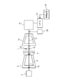
- FIG. 1 shows a plant in a reference technique for explaining the present invention.
- An example of a twin-shaft gas turbine and a compressor driven by it is shown.
- the gas turbine 104 includes a compressor, a combustor, and a turbine.
- the gas turbine 104 includes a high pressure side shaft 110 and a low pressure side shaft 112.
- the high-pressure side shaft 110 is connected to the motor 102. Turning of the high-pressure side shaft 110 is performed by the motor 102.
- the low pressure side shaft 112 is connected to the compressor 114 and functions as a drive shaft of the compressor 114.
- a gear 118 of a pickup device which is a detector for detecting the rotation speed, is attached to the low pressure side shaft 112.
- a pickup device 120 is installed at a position corresponding to the gear 118.
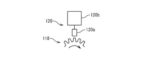
- FIG. 2 shows an electromagnetic rotary pickup (MPU, Magnetic Pickup) which is an example of the pickup device 120.
- the gear 118 rotates coaxially with the low pressure side shaft 112 at the same speed.
- the head 120a of the pickup device 120 includes a coil and a permanent magnet disposed therein.
- the gear 118 rotates in the vicinity of the head 120a, the distance between the head 120 and the end of the gear 118 changes periodically in a time-series manner due to a periodic uneven pattern (wheel teeth) in the circumferential direction of the gear 118. .
- This change causes a current to flow through the coil of the head 120.
- the time-series detected value of the current magnitude changes in synchronization with the rotation of the gear 118.
- the control device 120b generates a rotation speed signal indicating the rotation speed of the gear 118 based on the change in current.
- a motor 116 is connected to the compressor 114.
- the motor 116 is driven by a variable frequency driving device 122 and a control device 124.
- the motor 116 drives the low-pressure side shaft 112 as a helper motor that supplements the output when the output of the turbine 104 is insufficient to drive the compressor 114 under desired operating conditions.
- Rotational speed signal generated by the pickup device 120 is input to the control device 124.
- the control device 124 performs feedback control of the motor 116 based on the detected rotational speed of the low-pressure side shaft 112 indicated by this signal.
- the existing helper motor 116 and the rotational speed detection pickup 120 can be used.
- the generated voltage is low when the rotation speed of the gear 118 is small. Therefore, it is suitable for detection of the rotational speed during normal operation, but is not suitable when the rotational speed is small (about 100 rpm or less). Since the rotation speed region of the turning operation is about 10 to 20 rpm, the pickup device 120 cannot generate a rotation speed signal during turning, and the motor 116 cannot be controlled appropriately.
- An object of the present invention is to provide a technique that enables turning of a compressor driven by a multi-shaft gas turbine.
- a compressor driving device applies a driving force to a compressor connected to a low pressure side shaft of a multi-shaft gas turbine including a high pressure side shaft and a low pressure side shaft.
- the compressor driving device controls the electric motor that generates the driving force and the rotating speed when the compressor is turned, and supplements the torque when the torque generated by the gas turbine is insufficient.
- a control unit for controlling the electric motor to perform the helper motor operation.
- the low pressure side shaft is also turned during turning.
- the compressor driving device further includes a low speed pickup for detecting a rotation speed of the low pressure side shaft during turning and outputting a detection signal for turning indicating the detected rotation speed.
- the control unit controls the electric motor based on the turning detection signal during turning.
- a rotation speed detection member is provided at a position corresponding to the low speed pickup of the low pressure side shaft.
- the low speed pickup includes a head, and generates a turning detection signal by detecting the distance between the head and the periodic uneven pattern of the rotation speed detection member provided on the low pressure side shaft in time series.
- the compressor driving device further includes a high-speed pickup that detects the rotation speed of the low-pressure side shaft and outputs a helper motor rotation speed signal during operation of the helper motor.
- the control unit controls the electric motor based on the helper motor rotation number signal when the helper motor is operated.
- the high-speed pickup includes a coil, and the current flowing through the coil due to the movement of the periodic uneven pattern of the rotation speed detection member provided on the low-pressure side shaft is provided.
- a helper motor rotation speed detection signal is generated based on the change.
- control unit includes a protection circuit that stops turning when the number of rotations of the low-pressure side shaft exceeds a predetermined value.
- a gas turbine plant includes a multi-shaft gas turbine including a high-pressure side shaft and a low-pressure side shaft, a compressor coupled to the low-pressure side shaft, and a driving force applied to the compressor. And a compressor driving device.
- the operation method of the compressor is an operation method of a compressor connected to a low pressure side shaft of a multi-shaft gas turbine including a high pressure side shaft and a low pressure side shaft.
- the method includes a step of controlling the electric motor so as to generate a turning rotational speed when the compressor is turned, and a helper motor operation for supplementing the torque when the torque generated by the gas turbine is insufficient. And a step of controlling the electric motor.
- the present invention provides a technique that enables turning of a compressor driven by a multi-shaft gas turbine.
- FIG. 1 shows a plant in the reference technology.
- FIG. 2 shows an electromagnetic pickup.
- FIG. 3 shows a gas turbine plant according to the first embodiment.
- FIG. 4 is a control logic diagram according to the first embodiment.
- FIG. 5 shows a gas turbine plant according to the second embodiment.
- FIG. 6 is a control logic diagram according to the second embodiment.
- FIG. 3 shows a two-shaft gas turbine plant according to the first embodiment.
- the gas turbine 4 includes a compressor, a combustor, and a turbine.
- the compressor sucks air and compresses it.
- the compressed air is supplied to the combustor.
- the compressed air and fuel are combusted in the combustor to generate combustion gas.
- the turbine is driven by the combustion gas.
- the turbine upstream side 6 includes a compressor and a moving blade on the high pressure side of the turbine. These are driven by the high-pressure side shaft 10.
- the turbine downstream side 8 includes a low pressure side moving blade driven by a low pressure side shaft 8.
- the high-pressure side shaft 10 and the low-pressure side shaft are rotatably disposed on the same axis by respective bearings.
- the high-pressure side shaft 10 and the low-pressure side shaft are not structurally connected and can rotate independently.
- the low-pressure side shaft 10 is driven through the flow of gas, that is, the combustion gas supplied from the high-pressure side moving blade moves the low-pressure side moving blade.
- Compressor 14 is connected to gas turbine 4 as a load.
- This compressor constitutes a part of another heat cycle engine (not shown).
- the compressor 14 in the present embodiment is driven using the low pressure side shaft 12 as a drive shaft. Therefore, as will be described later, turning of the low pressure side shaft 12 of the gas turbine 4 is also performed by turning of the compressor 14.
- the compressor drive device that drives the compressor 14 includes a motor 16 that is an electric motor that applies torque to the low-pressure side shaft 12 that is a drive shaft of the compressor 14, and a control unit that controls the motor.
- the control unit includes a variable frequency driving device 22 and a control device 24.
- the compressor drive device further includes a gear 18 that is a member for detecting the number of rotations of the low-pressure shaft 12 and a high-speed pickup 20.
- a motor 16 is connected to the compressor 14.
- the motor 16 is controlled by a variable frequency driving device 22 and a control device 24.
- a gear 18 is attached to the low pressure side shaft 12.
- the gear 18 is rotationally symmetric at a periodic angle around the central axis of the low pressure side shaft 12, has teeth formed at a predetermined pitch in the circumferential direction, and has a low pressure around the same axis as the low pressure side shaft 12. It rotates at the same angular velocity as the side shaft 12.
- the high-speed pickup 20 has a head having a permanent magnet and a coil. When the gear 18 rotates, a current flows through the coil of the head.
- the current waveform or voltage waveform of this current shows a waveform that is synchronized with the rotation of the gear 18 (more precisely, the approaching and moving away of the teeth of the gear 18 near the head). Based on this waveform, the high speed pickup 20 generates a rotation speed signal indicating the rotation speed (rpm) of the low pressure side shaft 12.
- the motor 16 When the output of the gas turbine 4 is insufficient with respect to the load of the compressor 12, the motor 16 is operated as a helper motor to compensate for the shortage.
- the variable frequency drive device 22 and the control device 24 monitor the detected value of the exhaust temperature of the gas turbine 4, for example, and if the temperature rise exceeds a pre-stored predetermined reference, the output of the gas turbine 4 is insufficient. Is determined.
- the variable frequency drive device 22 and the control device 24 control the motor 16 in order to increase the torque of the motor as necessary in response to the determination indicating that the output is insufficient.
- FIG. 4 is a control logic diagram showing the control performed by the control device 24.
- signals input to the control device 24 are shown. These are input from a host control device for setting operating conditions such as the turbine 4 and the compressor 14. Alternatively, these signals are directly input from a detection device such as the high-speed pickup 20.
- the right column of FIG. 4 shows signals generated by the control device 24 in response to the input signals and used for control.
- the control device 24 When the setting signal S1 for setting the motor ON / OFF is input from the outside, the control device 24 outputs a motor ON / OFF signal S7 for turning on or off the motor 16 according to this signal.
- the control device 24 When the speed control signal S2 is input, the control device 24 generates a signal S8 and is set to the speed control mode. In the speed control mode, the control device 24 detects the rotational speed of the compressor 14 (that is, the detected value of the rotational speed of the low-pressure side shaft 12) and the speed set value S5 (exactly after being limited by the limiter L3). The motor 16 is controlled so that the deviation from the speed set value S11) becomes small.
- the control device 24 generates a speed signal S10 based on the rotation speed signal S4 output from the high speed pickup 20 and treats it as a detected value of the rotation speed.
- the control device 24 When the setting signal S3 for setting to the torque control mode is input, the control device 24 generates a signal S9 and is set to the torque control mode. At this time, the control signal S9 is output on condition that the setting signal S2 does not indicate that the speed control is set by the logic elements L1 and L2. In the speed control mode, the control device 24 controls the motor 16 so that the deviation between the detected value of the torque of the compressor 14 (that is, the torque of the low pressure side shaft 12) and the torque setting value S6 given from the outside becomes small. With the above control, the motor 16 is controlled when the plant is started up and when the output of the gas turbine 4 is insufficient with respect to the load.
- a turning device 26 is installed so that it can be connected to the low pressure side shaft 12 of such a plant.
- the turning device 26 is connected to the low pressure side shaft 12 via a gear mechanism. This gear mechanism is disconnected from the low pressure side shaft when turning is completed. Therefore, the load of the turning device 26 is not applied to the low pressure side shaft 12 during normal operation. In such a plant, turning is performed during a period in which the normal operation of the gas turbine 4 is stopped.
- the high-pressure side shaft 10 is turned by the motor 2.
- the low pressure side shaft 12, which is the rotation axis of the compressor 14, is turned by the turning device 26.
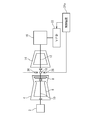
- FIG. 5 shows a configuration of a two-shaft gas turbine plant according to the second embodiment.
- the motor 2, the gas turbine 4, the high-pressure side shaft 10, the low-pressure side shaft 12, the compressor 14, the motor 16, the variable frequency driving device 22, and the high-speed pickup 20 are the same as in the first embodiment.
- the plant in this embodiment is different from the first embodiment in that the low speed pickup 28 is installed and the control logic of the control device 24a is different. As a result, as will be described in detail below, the turning device 26 dedicated for turning the compressor installed in the second embodiment is unnecessary.
- the low speed pickup 28 detects the rotation speed of the low pressure side shaft 12 using the gear 18 attached to the low pressure side shaft 12.
- the gear 18 may be the gear 18 of the high-speed pickup 20 used for normal operation, or a gear dedicated to the low-speed pickup 28 may be used.
- the low speed pickup 28 is a detector suitable for an application for detecting the rotation speed of the low pressure side shaft 12 during the turning operation of the compressor 14.
- An example of such a detector is a displacement sensor that detects a distance between the head of the detector and an object in real time and generates a detection signal indicating the distance.
- the gear rotates to synchronize with the timing when the teeth pass near the head. A periodically changing detection signal is obtained.
- the rotational speed of the low pressure side shaft 12 can be detected from the detection signal.
- the displacement sensor includes a coil in its head.
- a high frequency magnetic field is generated by flowing a high frequency current from the power source connected to the displacement sensor to the coil of the head. Due to this high frequency magnetic field, an eddy current flows in a metal object near the head. By detecting a change in the impedance of the coil due to the flow of eddy current, the distance between the head and the object can be detected.
- the detection device can be used for high speed.
- the functions of both the pickup 20 and the low speed pickup 28 can be realized.
- turning control can be realized at low cost by preparing a dedicated detection device for each of high-speed rotation and low-speed rotation as shown in FIG.
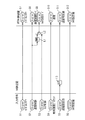
- FIG. 6 is a control logic diagram showing the control performed by the control device 24a.
- signals input to the control device 24a are shown. These are input from a host control device for setting operating conditions such as the turbine 4 and the compressor 14. Alternatively, it is directly input from a detection device such as the high-speed pickup 20 or the low-speed pickup 28.
- the right column of FIG. 6 shows signals generated by the control device 24a in response to the input signals.
- ON is represented by a value 1
- OFF is represented by a value 0.
- the control device 24a includes a protection circuit L11.
- the protection circuit L11 turns on the motor only when a certain condition is satisfied when a signal of value 1 indicating that the motor is turned on is input as the setting signal S21 for setting the motor ON / OFF.
- a motor ON / OFF signal S30 is output.
- a protection operation for outputting a motor ON / OFF signal S30 for turning off the motor is executed.
- the protection circuit L11 includes a comparator L12.
- a signal S26 indicating the rotation speed of the low-pressure side shaft 12 detected by the low-speed speed pickup 28 is input to the comparator L12.
- the comparator L12 When the input rotational speed is less than or equal to the predetermined value, the comparator L12 outputs a value 0.
- the comparator L12 When the input rotation speed exceeds a predetermined value, the comparator L12 outputs a value of 1.
- the output of the comparator L12 and a signal S29 output from the control device 24a and indicating the regenerative operation of the motor 16 are input to the OR element L13 (value 1 if the regenerative operation is being performed, value 0 if not). To do.
- the AND element L14 receives the output of the OR element L13 and the setting signal S22 of the turning mode of the motor 16 (value 1 if turning, value 0 otherwise).
- the output value of the AND element L14 is inverted by the inverter L15 and input to one terminal of the AND element L16.
- the motor ON / OFF setting signal S21 is input to the other terminal of the AND element L16.
- the motor ON / OFF signal S30 takes the value 1 only when the motor ON / OFF setting signal S21 has the value 1 and the following conditions are satisfied.
- the motor 16 is not performing the turning operation of the compressor 14 (the setting signal S22 has a value of 0).
- the motor 16 is in the turning operation of the compressor 14, the rotation speed of the low-pressure side shaft 12 detected by the low-speed speed pickup 28 does not exceed the predetermined value, and the motor 16 is not in the regenerative operation.
- the setting signal S22 is further input to the input terminal of the AND element L19 via the inverter L17.
- the speed control mode setting signal S23 is input to the other input terminal of the AND element L19.
- a signal S37 instructing to set the control of the motor 16 to the speed control mode is generated by the output signal of the AND element L19.
- the rotation speed signal generated by the high-speed pickup 20 for normal operation is input to the control device 24a as the normal rotation speed signal S25.
- the regular rotation speed signal S25 is handled as a detection value of the rotation speed.
- the rotation speed signal generated by the turning low speed pickup 28 is input to the control device 24a as the turning detection signal S26.
- the common detection signal S25 and the turning detection signal S26 are input to the switch L26.
- the switch L26 selects and outputs the common rotation speed signal S25.
- the switch L26 selects and outputs the turning detection signal S26 when the turning setting signal S22 is 1.
- the output of the switch L26 is used for speed control of the motor 16 as a speed detection signal S33.
- the upper limit value of the speed set value S27 is limited by the high value side limiter L27 and the low value side limiter L28.
- the high value side limiter L27 limits the rotation speed of the low pressure side shaft 12 during normal operation (for example, an upper limit value of 5000 rpm).
- the low value side limiter L28 limits the rotation speed of the low pressure side shaft 12 during turning (for example, an upper limit value of 20 rpm).
- the switch L29 selects and outputs the output of the high limiter L27 when the turning setting signal S22 is 0. When the turning setting signal S22 is 1, the switch L29 selects and outputs the output of the low value side limiter L27.
- Switch L30 selects a signal according to the output of AND element L14.
- the output of the AND element L14 is 0 during normal service operation or turning.
- the switch L30 selects the output of the switch L29 and outputs it as the speed set value S34.
- the speed set value S34 is used for control as a set value for the rotational speed of the low-pressure side shaft 12 in the turning mode and in the speed control mode.
- the output of the AND element L14 is the value 1.
- the turning setting signal S22 has a value 1 and the motor regeneration signal S29 has a value 1.
- the comparator L12 outputs value 1. That is, when the rotation speed of the low pressure side shaft 12 exceeds a predetermined value during the turning operation.
- the selector L30 outputs the value 0.0 generated by the signal generator L31 as the speed set value S34. With this control, it is possible to avoid setting an undesirable speed setting value when an abnormal event occurs during turning.
- the torque set value S28 is used for control as a set value of torque generated by the low-pressure side shaft 12 in the torque control mode.
- the motor 16 bears part of the torque as a helper motor that supplements the load.
- the embodiment of the present invention has been described above by taking a two-shaft gas turbine as an example, the same effect can be obtained even in the case of a multi-shaft gas turbine having three or more shafts.
- the shaft driven as a common shaft with the compressor corresponds to the low pressure side shaft
- the other shafts correspond to the high pressure side shaft.
Landscapes
- Engineering & Computer Science (AREA)
- Mechanical Engineering (AREA)
- General Engineering & Computer Science (AREA)
- Control Of Positive-Displacement Pumps (AREA)
- Control Of Positive-Displacement Air Blowers (AREA)
- Structures Of Non-Positive Displacement Pumps (AREA)
Abstract
Description
以下、図面を参照して本発明の実施形態について説明する。図3は、第1の実施形態に係る二軸式ガスタービンプラントを示す。ガスタービン4は、圧縮機、燃焼器、タービンを備える。圧縮機は空気を吸入して圧縮する。圧縮された空気は燃焼器に供給される。燃焼器において圧縮された空気と燃料とが燃焼して燃焼ガスが生成される。その燃焼ガスによってタービンが駆動される。
図5は、第2の実施形態に係る二軸式ガスタービンプラントの構成を示す。モータ2、ガスタービン4、高圧側シャフト10、低圧側シャフト12、圧縮機14、モータ16、可変周波数駆動装置22、高速用ピックアップ20については、第1の実施形態と同様である。
(1)モータ16が圧縮機14のターニング運転を行っていない(設定信号S22が値0)。
(2)モータ16が圧縮機14のターニング運転中、且つ低速度用速度ピックアップ28が検出した低圧側シャフト12の回転数が所定値を越えていない、且つモータ16が回生運転中でない。
(1)ターニングの設定信号S22が値1であり、且つモータ回生の信号S29が値1である場合。
(2)ターニングの設定信号S22が値1であり、比較器L12が値1を出力した場合。すなわちターニング運転中に低圧側シャフト12の回転数が所定値を上回った場合。
これらの異常な事象が発生した場合、選択器L30は信号発生器L31が発生した値0.0を速度設定値S34として出力する。この制御により、ターニング中に異常な事象が発生した場合に、望ましくない速度設定値が設定されてしまうことが避けられる。
Claims (9)
- 高圧側シャフトと低圧側シャフトとを備える複数軸式ガスタービンの低圧側シャフトに接続された圧縮機に駆動力を与える圧縮機駆動装置であって、
前記駆動力を生成する電動機と、
前記圧縮機のターニングを行う場合にターニング回転数を生成するように前記電動機を制御し、前記ガスタービンが発生するトルクが不足する場合に前記トルクを補うためのヘルパーモータ運転を行うように前記電動機を制御する制御部
とを具備する圧縮機駆動装置。 - 請求の範囲1に記載された圧縮機駆動装置であって、
前記ターニング時に前記低圧側シャフトもターニングされる
圧縮機駆動装置。 - 請求の範囲1又は2に記載された圧縮機駆動装置であって、
更に、前記ターニング時に前記低圧側シャフトの回転数を検出して検出した回転数を示すターニング用検出信号を出力する低速用ピックアップを具備し、
前記制御部は、前記ターニング時に前記ターニング用検出信号に基づいて前記電動機を制御する
圧縮機駆動装置。 - 請求の範囲3に記載された圧縮機駆動装置であって、
前記低圧側シャフトの前記低速用ピックアップに対応する位置に回転数検出用部材が設けられ、
前記低速用ピックアップはヘッドを備え、前記ヘッドと前記低圧側シャフトに設けられた回転数検出用部材の周期的な凹凸パターンとの間の距離を時系列的に検出することにより前記ターニング用検出信号を生成する
圧縮機駆動装置。 - 請求の範囲3又は4に記載された圧縮機駆動装置であって、
更に、前記ヘルパーモータ運転時に前記低圧側シャフトの回転数を検出してヘルパーモータ回転数信号を出力する高速用ピックアップを具備し、
前記制御部は、前記ヘルパーモータ運転時に前記ヘルパーモータ回転数信号に基づいて前記電動機を制御する
圧縮機駆動装置。 - 請求の範囲5に記載された圧縮機駆動装置であって、
前記高速用ピックアップはコイルを備え、前記低圧側シャフトに設けられた回転数検出用部材の周期的な凹凸パターンが移動することによる前記コイルを流れる電流の周期的な変化に基づいて前記ヘルパーモータ回転数検出信号を生成する
圧縮機駆動装置。 - 請求の範囲1から6のいずれかに記載された圧縮機駆動装置であって、
前記制御部は、前記低圧側シャフトの回転数が所定値を上回った場合に前記圧縮機の前記ターニングを中止する保護回路を具備する
圧縮機駆動装置。 - 高圧側シャフトと低圧側シャフトとを備える複数軸式ガスタービンと、
前記低圧側シャフトに結合された圧縮機と、
前記圧縮機に駆動力を与える圧縮機駆動装置とを具備し、
前記圧縮機駆動装置は、
前記駆動力を生成する電動機と、
前記圧縮機のターニングを行う場合にターニング回転数を生成するように前記電動機を制御し、前記ガスタービンが発生するトルクが不足する場合に前記トルクを補うためのヘルパーモータ運転を行うように前記電動機を制御する制御部とを具備する
ガスタービンプラント。 - 高圧側シャフトと低圧側シャフトとを備える複数軸式ガスタービンの低圧側シャフトに接続された圧縮機の運転方法であって、
前記圧縮機のターニングを行う場合にターニング回転数を生成するように前記電動機を制御する工程と、
前記ガスタービンが発生するトルクが不足する場合に前記トルクを補うためのヘルパーモータ運転を行うように電動機を制御する工程
とを具備する圧縮機の運転方法。
Priority Applications (3)
| Application Number | Priority Date | Filing Date | Title |
|---|---|---|---|
| US13/059,721 US8935924B2 (en) | 2008-11-12 | 2009-08-31 | Driving device and an operation method of a compressor |
| EP09825976.5A EP2325491B1 (en) | 2008-11-12 | 2009-08-31 | Compressor drive device and operation method |
| AU2009315131A AU2009315131B2 (en) | 2008-11-12 | 2009-08-31 | Compressor drive device and operation method |
Applications Claiming Priority (2)
| Application Number | Priority Date | Filing Date | Title |
|---|---|---|---|
| JP2008290391A JP5167078B2 (ja) | 2008-11-12 | 2008-11-12 | 圧縮機の駆動装置と運転方法 |
| JP2008-290391 | 2008-11-12 |
Publications (1)
| Publication Number | Publication Date |
|---|---|
| WO2010055723A1 true WO2010055723A1 (ja) | 2010-05-20 |
Family
ID=42169863
Family Applications (1)
| Application Number | Title | Priority Date | Filing Date |
|---|---|---|---|
| PCT/JP2009/065164 Ceased WO2010055723A1 (ja) | 2008-11-12 | 2009-08-31 | 圧縮機の駆動装置と運転方法 |
Country Status (5)
| Country | Link |
|---|---|
| US (1) | US8935924B2 (ja) |
| EP (1) | EP2325491B1 (ja) |
| JP (1) | JP5167078B2 (ja) |
| AU (1) | AU2009315131B2 (ja) |
| WO (1) | WO2010055723A1 (ja) |
Cited By (1)
| Publication number | Priority date | Publication date | Assignee | Title |
|---|---|---|---|---|
| US11105270B2 (en) | 2016-09-27 | 2021-08-31 | Mitsubishi Heavy Industries Compressor Corporation | Control device and control method for rotary machine, and rotary machine unit equipped with control device |
Families Citing this family (17)
| Publication number | Priority date | Publication date | Assignee | Title |
|---|---|---|---|---|
| JP4939612B2 (ja) * | 2007-12-27 | 2012-05-30 | 三菱重工業株式会社 | 圧縮機の制御装置と制御方法 |
| US8820046B2 (en) * | 2009-10-05 | 2014-09-02 | General Electric Company | Methods and systems for mitigating distortion of gas turbine shaft |
| IT1401275B1 (it) * | 2010-07-30 | 2013-07-18 | Nuova Pignone S R L | Metodo e dispositivo per controllare un riavvio a caldo di un compressore centrifugo |
| ITFI20110269A1 (it) * | 2011-12-12 | 2013-06-13 | Nuovo Pignone Spa | "turning gear for gas turbine arrangements" |
| US9417258B2 (en) * | 2012-09-10 | 2016-08-16 | United Technologies Corporation | Sensor and tooth arrangement for shaft speed detection |
| US9605597B2 (en) | 2013-06-13 | 2017-03-28 | Solar Turbines Incorporated | Variable frequency drive power ride thru |
| JP2015001153A (ja) * | 2013-06-13 | 2015-01-05 | 三菱電機株式会社 | 発電機起動システム |
| JP5914777B2 (ja) * | 2013-12-26 | 2016-05-11 | グアンドン メイジ コムプレッサ カンパニー リミテッド | 圧縮機のトルクの自動補正方法、その装置及び圧縮機並びにその制御方法 |
| CN103742396B (zh) * | 2013-12-26 | 2016-04-06 | 广东美芝制冷设备有限公司 | 压缩机力矩自动补偿方法、装置和压缩机及其控制方法 |
| US9273610B2 (en) * | 2014-05-20 | 2016-03-01 | Solar Turbines Incorporated | Starter/generator combination with all variable frequency drives |
| CN105927559A (zh) * | 2015-04-22 | 2016-09-07 | 张澄宇 | 微小型分体式涡喷驱动压气机 |
| EP3211184B1 (en) | 2016-02-29 | 2021-05-05 | Raytheon Technologies Corporation | Bowed rotor prevention system and associated method of bowed rotor prevention |
| US10787933B2 (en) * | 2016-06-20 | 2020-09-29 | Raytheon Technologies Corporation | Low-power bowed rotor prevention and monitoring system |
| WO2019152915A2 (en) * | 2018-02-02 | 2019-08-08 | Magnetic Pumping Solutions, Llc | Method and system for controlling downhole pumping systems |
| US12060833B2 (en) | 2021-08-10 | 2024-08-13 | Rolls-Royce North American Technologies, Inc. | Gas turbine engine system with motor-generator |
| US12140089B2 (en) | 2021-12-27 | 2024-11-12 | Rolls-Royce North American Technologies, Inc. | Gas turbine engine system with generator |
| US12320295B2 (en) | 2021-12-27 | 2025-06-03 | Rolls-Royce North American Technologies, Inc. | Gas turbine engine system with generator |
Citations (4)
| Publication number | Priority date | Publication date | Assignee | Title |
|---|---|---|---|---|
| JPS5990723A (ja) | 1982-11-15 | 1984-05-25 | Hitachi Ltd | ガスタ−ビン |
| JPH10121908A (ja) * | 1996-10-16 | 1998-05-12 | Toshiba Corp | 発電設備のターニング装置 |
| JP2005248751A (ja) * | 2004-03-02 | 2005-09-15 | Ebara Corp | ガスタービン、ガスタービンの始動方法及び停止方法 |
| JP2007040253A (ja) * | 2005-08-05 | 2007-02-15 | Chugoku Electric Power Co Inc:The | 発電プラントの停止方法 |
Family Cites Families (6)
| Publication number | Priority date | Publication date | Assignee | Title |
|---|---|---|---|---|
| US6931856B2 (en) * | 2003-09-12 | 2005-08-23 | Mes International, Inc. | Multi-spool turbogenerator system and control method |
| US7526926B2 (en) * | 2003-11-06 | 2009-05-05 | Exxonmobil Upstream Research Company | Method for efficient nonsynchronous LNG production |
| US7513120B2 (en) * | 2005-04-08 | 2009-04-07 | United Technologies Corporation | Electrically coupled supercharger for a gas turbine engine |
| US7615881B2 (en) * | 2006-12-20 | 2009-11-10 | Hamilton Sundstrand Corporation | Power turbine speed control using electrical load following |
| US8261552B2 (en) * | 2007-01-25 | 2012-09-11 | Dresser Rand Company | Advanced adiabatic compressed air energy storage system |
| WO2012003471A2 (en) * | 2010-07-02 | 2012-01-05 | Icr Turbine Engine Corporation | Improved multi-spool intercooled recuperated gas turbine |
-
2008
- 2008-11-12 JP JP2008290391A patent/JP5167078B2/ja not_active Expired - Fee Related
-
2009
- 2009-08-31 AU AU2009315131A patent/AU2009315131B2/en not_active Expired - Fee Related
- 2009-08-31 WO PCT/JP2009/065164 patent/WO2010055723A1/ja not_active Ceased
- 2009-08-31 EP EP09825976.5A patent/EP2325491B1/en active Active
- 2009-08-31 US US13/059,721 patent/US8935924B2/en not_active Expired - Fee Related
Patent Citations (4)
| Publication number | Priority date | Publication date | Assignee | Title |
|---|---|---|---|---|
| JPS5990723A (ja) | 1982-11-15 | 1984-05-25 | Hitachi Ltd | ガスタ−ビン |
| JPH10121908A (ja) * | 1996-10-16 | 1998-05-12 | Toshiba Corp | 発電設備のターニング装置 |
| JP2005248751A (ja) * | 2004-03-02 | 2005-09-15 | Ebara Corp | ガスタービン、ガスタービンの始動方法及び停止方法 |
| JP2007040253A (ja) * | 2005-08-05 | 2007-02-15 | Chugoku Electric Power Co Inc:The | 発電プラントの停止方法 |
Cited By (1)
| Publication number | Priority date | Publication date | Assignee | Title |
|---|---|---|---|---|
| US11105270B2 (en) | 2016-09-27 | 2021-08-31 | Mitsubishi Heavy Industries Compressor Corporation | Control device and control method for rotary machine, and rotary machine unit equipped with control device |
Also Published As
| Publication number | Publication date |
|---|---|
| US20110138816A1 (en) | 2011-06-16 |
| EP2325491B1 (en) | 2019-02-20 |
| AU2009315131B2 (en) | 2011-12-08 |
| US8935924B2 (en) | 2015-01-20 |
| EP2325491A4 (en) | 2017-02-08 |
| EP2325491A1 (en) | 2011-05-25 |
| AU2009315131A1 (en) | 2010-05-20 |
| JP2010116831A (ja) | 2010-05-27 |
| JP5167078B2 (ja) | 2013-03-21 |
Similar Documents
| Publication | Publication Date | Title |
|---|---|---|
| JP5167078B2 (ja) | 圧縮機の駆動装置と運転方法 | |
| US12000345B2 (en) | Surge recovery system and methods | |
| EP3693571B1 (en) | Transient operation control of a hybrid gas turbine engine | |
| US20220034262A1 (en) | Hybrid gas turbine engine system powered warm-up | |
| RU2654496C1 (ru) | Система регулируемого электрического двигателя и устройство с электрическим приводом | |
| EP3039255B1 (en) | Method for controlling coupling between a first machine and a second machine | |
| JP5441511B2 (ja) | タービンクリアランス縮小のための方法、システム、及び装置 | |
| EP3620634B1 (en) | Variable cycle compensation in a gas turbine engine | |
| JP5132674B2 (ja) | ガスタービン用モジュール式燃料供給装置 | |
| CN1580501A (zh) | 单轴复合循环发电设备及其运行方法 | |
| CN101660492A (zh) | 用于调整风力涡轮机偏航角的方法及设备 | |
| CN105947165A (zh) | 船舶舵机系统及船舶舵机系统的操舵控制方法 | |
| JP2005133708A (ja) | バルブ特性調整装置 | |
| EP3444464A1 (en) | System and method for rotating a gas turbine engine during a motoring cycle | |
| JP2011043135A (ja) | 航空機用ガスタービン・エンジンの制御装置 | |
| JP2016516937A (ja) | ウインドパーク、並びにウインドパークを制御する方法 | |
| US7140832B2 (en) | Method and system for rotating a turbine stator ring | |
| CN201858030U (zh) | 工程机械的发动机转速控制装置 | |
| CN113825897B (zh) | 包括上游锥体的除冰系统的涡轮机,以及相关方法 | |
| JP2019503163A (ja) | スター−デルタ切り替えを伴う真空ポンプ駆動装置 | |
| CN104712421A (zh) | 可变容量型增压器以及可变容量型增压器用控制器 | |
| CN120731315A (zh) | 用于控制涡轮发动机高压轴转速偏移的装置及方法 | |
| JP4016434B2 (ja) | 回転伝動部材の継手装置 | |
| CN104067015B (zh) | 转矩联接装置和用于调节转矩联接装置的方法 | |
| US20150158597A1 (en) | Emergency power generation via limited variable pitch fan blade |
Legal Events
| Date | Code | Title | Description |
|---|---|---|---|
| 121 | Ep: the epo has been informed by wipo that ep was designated in this application |
Ref document number: 09825976 Country of ref document: EP Kind code of ref document: A1 |
|
| WWE | Wipo information: entry into national phase |
Ref document number: 2009315131 Country of ref document: AU |
|
| WWE | Wipo information: entry into national phase |
Ref document number: 2009825976 Country of ref document: EP |
|
| WWE | Wipo information: entry into national phase |
Ref document number: 13059721 Country of ref document: US |
|
| ENP | Entry into the national phase |
Ref document number: 2009315131 Country of ref document: AU Date of ref document: 20090831 Kind code of ref document: A |
|
| NENP | Non-entry into the national phase |
Ref country code: DE |